

Page 1

IMPORTANT WARRANTY INFORMATION! PLEASE READ
Return Policy on Kits When Not Purchased Directly From Vectronics: Before continuing any
further with your VEC kit check with your Dealer about their return policy. If your Dealer
allows returns, your kit must be returned
Return Policy on Kits When Purchased Directly From Vectronics: Your VEC kit may be
returned to the factory
once you begin installing and sold ering parts, you es sentia lly take over the role of th e device's
manufacturer. From this p oint on, neith er Vect ronics nor its d ealers can reas onab ly be h eld
accountable for the quality or the outcome of your work. Because of this, Vectronics cannot
accept return of any kit-in-progress or completed work as a warranty item for any reason
whatsoever. If you are a new or inexperienced kit builder, we urge you to read the
manual carefully and determine whether or not you're ready to take on the job. If you
wish to change your mind and return your kit, you may--but you must do it
construction, and within ten (10) working days of the time it arrives.
Vectronics Warrants: You r kit c ontains each it em sp ecifi ed in th e parts list.
Missing Parts: If you determine, during your pre-construction inventory, that any part is
missing, please contact Vectronics and we'll send the missing item to you free of charge.
However,
the marking on one of the other items provided with the kit. Also, make certain an alternative
part hasn't been substituted for the i tem you're missin g. If a sp ecific part is n o longer available,
or if Engineering has d etermined that an alternative component is more suitable, Vectroni cs
reserves the right to make substitutions at any time. In most cases, these changes will be
clearly noted in an addendum to th e manual.
Defective Parts: Today's electronic part s are physically and electrica lly resilient, and def ective
components are rare. However, if you discover an it em during your pre-c onstruction in ventory
that's obviously broken or unserviceable, we'll rep lace it. Just return th e part to Vectronics at
the address below accompanied with an explanation. Upon rec eipt, we'll test it. If it's defectiv e
and appears unused, we'll ship you a new one right away at no charge.
before you
in its pre-assembled condition only.
contact Vectronics,
before you
please look ca refu lly
begin construction.
The reason for this st ipulation i s,
before you
to confirm you haven't misread
begin
Missing or Defective Parts After You Begin Assembly: Parts and materials lost or damaged
after construction begins
supplied with VEC kits are relatively inexpensive and Vectronics can replace them for a
reasonable charge. Simp ly c ontact t he factory with a complet e d esc ription. We'll p roces s you r
order quickly and get you back on track.
Factory Repair After You Begin Assembly:
specifically excluded from coverage by the Vectronics warranty.
service to customers, t echnic ian s a re a vailab le t o eva luate and r epai r malfunct ionin g kits f or a
minimum service fee of 518.00 (1/2 hour rate) plus 57.00 shipping and handling (prices subject
to change). To qualify for repair service, your kit must be fully completed, unmodified, and the
printed circuit board assembled using rosin-core solder. 1n the event your repair will require
more than an hour to fix (or 536.00, subj ect to chan ge), ou r t echnicians will c ontact you in
advance by telephone before performing the work. Defective units should be shipped prepaid
Vectronics
1007 HWY 25 South
Starkville, MS 39759
When shipping, pack your kit well and include the minimum payment plus shipping and
handling charges (525.00 tota l). No work can b e perfo rmed with out p re-p ayment. Also, p r ovide
a valid UPS return address and a day time phone number where you may be reached.
are not covered und er the t er ms of thi s war rant y. Ho wever, most pa rts
Kits-in progress and completed kits are
However, as a
Page 2

-
g
Single Side-Band Filter Kit
INTRODUCTION
Thank you for purchasing the VEC-830K Single Side-Band Filter kit. The
VEC-830K is a four stage, switch selectable filter, that will make "cleaning
up" Single Side-Band signals effortless and easy. With the VEC-830K you
bring up any hard to he ar signa l o ut o f a " band p ile up ," fo r ea sy liste ni ng, o r
get rid of unwanted , anno ying signals. The VEC-830 K a lso fe atur e s a
headphone output that will allow the use of standard mono headphones.
Although small in size, the VEC-830K is high on performance and reliability.
Powered from a 9volt transistor batten', the VEC-830K will provide you with
many hours of use.
TOOLS AND SUPPLIES
Construction Area: Kit construction requires a clean, smooth, and welllighted
area where you can easily organize and handle small parts without losing them.
An inexpensive sheet of white poster board makes an excellent construction
surface, while providing protection for the underlying table or desk. Welldiffused overhead lighting is a plus, and a supplemental high intensity desk
lamp will prove especially helpful for close-up work. Safety is an important
consideration. Be sure to use a suitable high-temperature stand for your
soldering iron, and keep the work area free of combustible clutter.
Universal Kit-buil di ng T o o ls: Altho ugh your pa rt icul ar kit ma y req uir e
additional items to complete, virtually all construction projects require a work
area outfitted with the followin
tools and supplies:
Page 3

VEC-830K Instruction Manual Single Side-Band Filter Kit
BEFORE YOU START BUILDING
Experience shows there are jour
and your kit will probably work on the first try! Here's what they are:
1. Installing the Wrong Part: It always pays to double-check each step. A 1K
and a 10K resistor may look
differently in an electronic circuit! Same for capacitors--a device marked
102 (or .001 uF) may have very different operating characteristics from one
marked 103 (or .01uF).
2. Installing Parts Backwards: Always check the polarity of electrolytic
capacitors to make sure the positive (+) lead goes in the (+) hole on the
circuit board. Transistors have a flat side or emitter tab to help you identify
the correct mounting position. ICs have a notch or dot at one end indicating
the correct direction of insertion. Diodes have a banded end indicating
correct polarity. Always double-check--especially before applying power to
the circuit!
3. Faulty Solder Connections: Inspect for cold-solder joints and solder
bridges. Cold solder joints happen when you don't fully heat the
connection--or when metallic corrosion and oxide contaminate a
component lead or pad. Solder bridges form when a trail of excess solder
shorts pads or tracks together (see Soldering Tips below).
common mistakes
almost
the same, but they may act very
builders make. Avoid these,
4.
Omitting or Misreading a Part: This is easier to do than you might think!
Always double-check to make sure you completed each step in an assembly
Soldering Tips:
Cleanliness
soldering. Before you install and solder each part, inspect leads or pins for
oxidation. If the metal surface is dull, sand with fine emery paper until shiny.
Also, clean the oxidation and excess solder from the soldering iron tip to
ensure maximum heat transfer. Allow the tip of your iron to contact both the
lead and pad for about one second (count "one-thousand-one") before feeding
solder to the connection. Surfaces must become hot enough for solder to flow
smoothly.
will wick around the lead toward the tip, wetting all exposed surfaces. Apply
solder sparingly, and do not touch solder directly to the hot iron tip to promote
rapid melting.
and good
Feed solder to the opposite side of the lead from your iron tip--solder
heat distribution
are the two secrets of professional
Page 4
VEC-830K Instruction Afanual Single Side-Band Filter
Desoldering Tips:
If you make a mistake and need to remove a part, follow these instructions
carefully! First, grasp the component with a pair of hemostats or needle-nose
pliers. Heat the pad beneath the lead you intend to extract, and pull gently. The
lead should come out. Repeat for the other lead. Solder may fill in behind the
lead as you extract it--especially if you are working on a double-sided board
with plate-through holes. Should this happen, try heating t he pad agai n and
inserting a common pin into the hole. Solder won't stick to the pin's chromium
plating. When the pad cools, remove the pin and insert the correct component.
For ICs or multi-pin parts, use desoldering braid to remove excess solder before
attempting to extract the part. Alternatively, a low-cost vacuum-bulb or springloaded solder sucker may be used. Parts damaged or severely overheated during
extraction should be replaced rather than reinstalled.
Work Habits:
Kit construction requires the ability to follow detailed instructions and, in many
cases, to perform new and unfamiliar tasks. To avoid making needless mistakes,
work for short periods when you're fresh and alert. Recreational construction
projects a re more informative and more fun when you take your time. Enjoy!
Sorting and Reading Resistors:
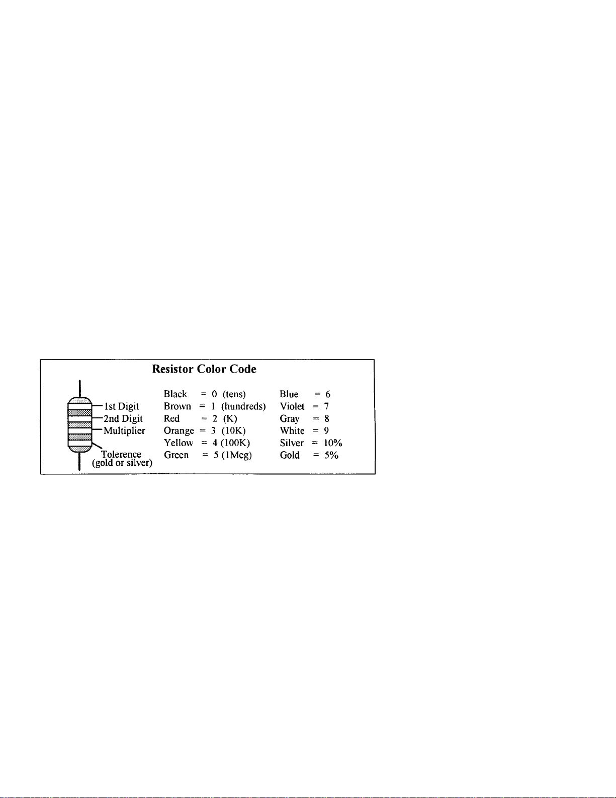
The electrical value of resistors is indicated by a color code (shown below). You
don't have to memorize this code to work with resistors, but you do need to
understand how it works:
When you look at a resistor, check its multiplier code first. Any resi stor with a
black multiplier band falls between 10 and 99 ohms in value. Bro wn designates a
value between 100 and 999 ohms. Red indicates a value from 1000 to 9999
ohms, which is also expressed as 1.0K to 9.9 K. An orange multiplier band
designates 10K to 99K, etc. To sort and inventory resistors, first separate them
into groups by multiplier band (make a pile of 10s, 100s, Ks,
Page 5
VEC-83 OK Instruction Manual Single Side-Band Filter
,
I0Ks, etc.). Next, sort each group by specific value (1K, 2.2K, 4.7K. etc.). This
procedure makes the inventory easier, and also makes locating specific parts
more convenient later on during construction. Some builders find it especially
helpful to arrange resistors in ascending order along a strip of double-sided tape.
Some VEC kits may contain molded chokes which appear, at first glance, similar
to resistors in both shape and band marking. However, a closer look will enable
you to differentiate between the two--chokes are generally larger in diameter and
fatter at the ends than resistors. When doing your inventory, separate out any
chokes and consult the parts list for specific color-code information.
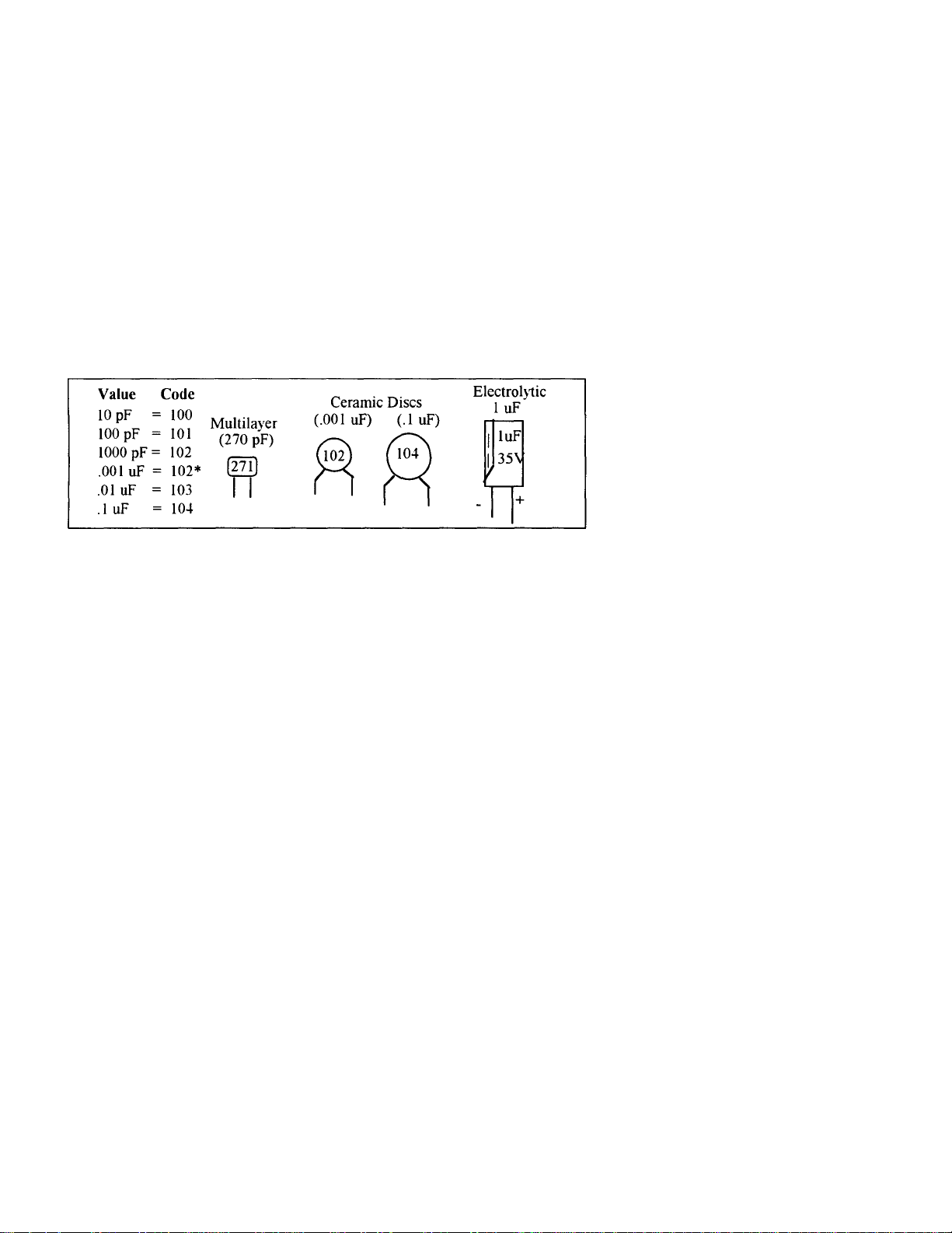
Reading Capacitors:
Unlike resistors, capacitors no longer use a color code for value
Instead
the value, or a 3-number code, is printed on the body.
As with resistors, it's helpful to sort capacitors by type, and then to arrange them
in ascending order of value. Small-value capacitors are characterized in pF (or
pico-Farads), while larger values are labeled in uF (or micro-Farads). The
transition from pF to uF occurs at 1000 pF (or .001 uF)*. Today, most
monolithic and disc-ceramic capacitors are marked with a three-number code.
The first two digits indicate a numerical value, while the last digit indicates a
multiplier (same as resistors).
Electrolytic capacitors are always marked in uF. Electrolytics are polarized
devices and must be oriented correctly during installation. If you become
confused by markings on the case, remember the uncut negative lead is slightly
shorter than the positive lead.
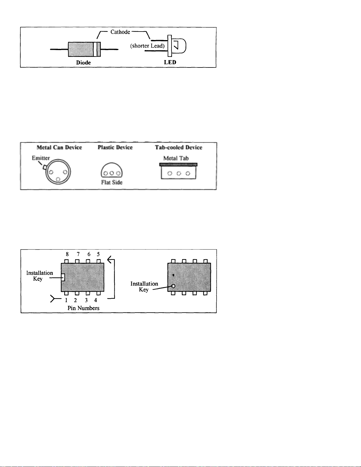
Diodes:
Diodes are also polarized devices that must be installed correctly. Always look
for the banded or cathode end when installing, and follow instructions carefully.
Page 6
C-830K Instruction Manual Sin
g
g
VE
Transistors:
If transistors are installed incorrectly, damage may result when power is applied.
Transistors in metal cases have a small tab near the emitter lead to identify
correct positioning. Semiconductors housed in small plastic cases (TO-92) have
an easily-identified flat side to identify mounting orientation. Many specialized
diodes and low-current voltage regulators also use this type packaging. Larger
plastic transistors and voltage regulators use a case backed with a prominent
metal tab to dissipate heat (T-220). Here orientation is indicated by the
nositionine of the colling tab.
le Side-Band Filter Kit
Inte
rated Circuits:
Proper IC positioning is indicated by a dot or square marking located on one end
of the device. A corresponding mark will be silk-screened on the PC board and
printed on the kit's parts-placement diagram. To identify specific IC pin numbers
for testing purposes, see the diagram below. Pin numbers always start at the
keyed end of the case and progress counter-clockwise around the device, as
shown:
Page 7

EC-830K Instr uction Manual Single Side-Band Filter Kit
g
PARTS LIST
Your kit should contain all of the parts listed below. Please go through the parts
bag to identify and inventory each item on the checklist before you start b uilding.
If any parts are missing or damaged, refer to the warranty section of this manual
for replacement instructions. If you can't positively identify an unfamiliar
item in the bag on the basis of the information given, set it aside u ntil all other
items are checked off. You may then be able to identify it by process of
elimination. Finally, your kit will go together more s moot hl y if parts ar e
organized by type and arranged by value ahead of time. Us e this inve nt ory as an
opportunity to sort and arrange parts so you can identify and find them quickly.
2 100K ohm resistor (brown-black-yellow-gold) R2,R3
2 150K ohm resistor (brown-green-yellow-gold) R4,R5
2 240K ohm resistor (red-yellow-yellow-gold) R6,R7
1 300K ohm resistor (orange-black-yellow-gold) R1
2 1.2M ohm resistor (brown-red-green-gold) R8,R9
5 1000 pF ploysterene capacitor (1000J)
3 470pF ploysterene capacitor (470J) C6,C7,C8
1 10 uF electrolytic capacitor (IOuf) C9
2 LM747 Op Amp IC Ul, U2
2 14-Pin Low Profile IC Socket For U1, U2
1 4P 4T Slide Switch SW1
8 6" insulated wires Circuit wiring
2 4-40 x 1/4" Phillips Machine Screws
1 9-volt battery snap; 8" GND, VCC
1Sin
1 I nstruction Manual
le Sided PC board VEC-830K
C1,C2,C3,C4,C
Page 8

VEC-830K Instruction Manual Single Side-Band Filter Kit
PARTS PLACEMENT DIAGRAM
Figure 1
Page 9

VEC-830K Instruction manual S ingle Side-Band Filter
y
g
p
y
p
g
g
-
-
Before assembling your kit, please take time to read and understand the VEC kit
warranty pr i nted on the inside cover of this manual. Also, r ead through t he
assembly instructions to make sure the kit does not exceed your skill level. Once
you begin constructio n, your kit will be non-returnable. Finally, if you haven't
already done so, please verify that all parts listed in the inventory are included.
If anything is missing or broken, refer to the warranty instructions for
replacing missing or damaged parts.
Note that part designators, such as R1, C3, etc., appear on a silk-screened legend
on the component-mounting side of the printed circuit board. This corresponds
with the parts placement page in the manual. All parts will be inserted on the
silk-screen side of the board.
If you have last-minute questions about what you need to build your kit, please
refer back to the section titled "Tools and Supplies". If you're ready to begin
now, here we go! The directions use two sets of check boxes. Check one when a
step is complete and use the other for double-checking your work before
operation.
1. Locate resistor R1. This is a 300K ohm resistor (orange-blackellow-gold).
Carefully bend the leads close to the resistor body to form right-angles (see
followin
diagram).
2. Insert R1 into its mounting holes so the resistor body rests against the board.
Solder in
3. Locate resistor R2. This is a 100K ohm resistor (brown-blackellow-gold).
Insert R2 into its mounting holes so the resistor body rests against the board.
4.
Solder in
5. Locate resistor R3. This is a 100K ohm resistor (brown-blackyellowold).
6. Locate resistor R4. This is a 150K ohm resistor (brown-greenyellowold).
lace and trim the leads.
lace and trim the leads.
Page 10

VEC-830K Instruction Manual Single Side-Band Filter
p
p
g
g
p
p
p
,
7. Insert R4 into its mounting holes so the resistor body rests against the
board. Solder in
8. Locate resistor R5. This is a 150K ohm resistor (brown-green-yellowgold).
9. Insert R5 into its mounting holes so the resistor body rests against the
board. Solder in
10. Locate resistor R6. This is a 240K ohm resistor (red-yellow-vellowold).
11. Insert R6 into its mounting holes so the resistor body rests against the
board. Solder in place and trim the leads.
12. Locate resistor R7. This is a 240K ohm resistor (red-yellow-yellowold).
13. Insert R7 into its mounting holes so the resistor body rests against the
board. Solder in place and trim the leads.
14. Locate resistor R8. This is a 1.2M ohm resistor (brown-red-greengold).
15. Insert R8 into its mounting holes so the resistor body rests against the
board. Solder in
lace and trim the leads.
lace and trim the leads.
lace and trim the leads.
16. Locate resistor R9. This is a 1.2M ohm resistor (brown-red-greengold).
17. Insert R9 into its mounting holes so the resistor body rests against the
board. Solder in
18. Locate capacitor Cl (1000pF). This is a polystyrene capacitor and will
be marked "10001" (actual value in pF). Carefully install C1, solder
in
lace, and trim the leads.
19. Locate capacitor C2 (1000pF). This is another polystyrene capacitor
and will be marked "10001" (actual value in pF). Carefully install C2
in the same manner as C1, solder in place, and trim the leads.
20. Locate capacitor C3 (1000pF). This is another polystyrene capacitor
and will be marked "10001" (actual value in pF). Carefully install C3
in the same manner as C2
lace and trim the leads.
solder in place, and trim the leads.
Page 11

VEC-830K Instruction Manual Single Side-Band Filter Kit
,
(4)
p
p
p
21.
Locate capacitor C4
and will be marked
the same manner as
22.
Locate capacitor C5
and will be marked
the same manner as
23.
Locate capacitor C6
be marked
manner as C5
24.
be marked
"470J"
solder in place, and trim the leads.
Locate capacitor
"470J"
(1000pF).
"1000J"
C3,
solder in place, and trim the leads.
(1000pF).
"1000J"
C4,
solder in place, and trim the leads.
(470pF).
(actual value in
C7 (470pF).
(actual value in
This is another polystyrene capacitor
(actual value in
pF).
This is another polystyrene capacitor
(actual value in
pF).
This is a polystyrene capacitor and will
pF).
Carefully install C6 in the same
This is a polystyrene capacitor and will
pF).
Carefully install
Carefully install
C4
Carefully install C5 in
C7
in the same
manner as C6, solder in place, and trim the leads.
25. Locate capacitor
be marked
manner as
"470J"
C7,
C8 (470pF).
(actual value in
This is a polystyrene capacitor and will
pF).
Carefully install C8 in the same
solder in place, and trim the leads.
26. Locate two (2) 6" insulated wires. Cut these wires in halt, making
four
27.
from the insulated ends of each
28.
Locate Point #1 on the circuit board. Insert one of the
3"
ieces.
Using the wire strippers, remove the about
3"
iece of insulated wire.
1/4" of
the insulation
3"
wires into
the hole at Point #1 on the circuit board. Solder in place and trim the
lead.
in
29.
Locate Point #2 on the circuit board. Insert one of the
into the hole at Point #2 on the circuit board. Solder in place and trim
the lead.
30.
Locate Point #3 on the circuit board. Insert one of the
into the hole at Point #3 on the circuit board. Solder in place and
trim the lead.
31.
Locate Point #4 on the circuit board. Insert one of the 3" wires into
the hole at Point #4 on the circuit board. Solder in place and trim the
32.
Locate one (1) 6" insulated wire. Cut this wire in half, making two
3"
(2)
pieces.
33.
Using the wire strippers, remove the about
from the insulated ends
of
each
3"
iece
1/4" of
of
insulated wire.
the insulation
3"
3"
wires
wires
Page 12

VEC-830K Instruction Manual Single Side-Band Filter Kit
,
g
g
p
g
(
34. Locate the hole on the circuit board labeled INPUT. Insert one of the
3" wires into this hole
35. Locate the hole on the circuit board labeled GND. Insert the
remainin
36. Locate the 8" battery snap. Insert the RED wire of the battery snap
into the hole on the circuit board labeled VCC. Solder in place and
trim the lead.
37. Locate the wire located at Point GND on the circuit board, and the
BLACK wire on the battery snap. Twist these two wires together,
being careful no t t o po ke yourse lf.
38. Locate a piece of insulated wire. Twist one end of this wire together
with the wires in the previous step and solder. Wrap this solder joint
with a small piece of electrical tape to keep it from shorting to other
parts of the circuit board. The other end is for audio ground.
39. Locate (1) 14 pin IC
40. Install the IC socket at the U 1 location on the circuit board.Be
careful to orient the socket correctly according to the "Parts
Placement" section Fi
41. Carefully bend over the four corner pins of the socket against the
solder
3" wire into this hole, solder in place and trim the lead.
ads on the solder side of the board. Solder all pins in place.
solder in place and trim the lead.
ure 1.
42. Locate the remainin
43. Install the IC socket at the U2 location on the circuit board. Be
careful to orient the socket correctly according to the "Parts
Placement" section Figure 1.
44. Carefully bend over the four corner pins of the socket against the
solder pads on the solder side of the board. Solder all pins in place.
45. Locate both LM747 op amp integrated circuits. Insert them into IC
sockets for U 1 and U2. Please refer to the
"Parts Placement" and Before You Start Building sections for proper
orientatio n and p la cement. Be sur e no t t o be nd any of t he p ins
underneath the IC body, and that all pins are inserted into the socket.
46. Locate the 4P4T slide switch
47. Inspect the slide switch for tarnished contacts. Remove any
tarnish with very fine sa ndpaper so t he contacts are nice and shiny.
This will provide a good soldering surface.
14 pin 1C
SW
Page 13

1 VEC-830K Instruction Manual Single Side-Band Filter
p
p
(1)
48. Connect wire located at Point #4 to Point A on SW1. Solder in
lace and trim the lead.
49. Locate capacitor C9 (IOuF). This is an electrolytic type capacitor
and will be marked "lOuF" with an arrow pointing to the negative end.
50. Trim the positive lead of C9 so about only 3/8" of the lead remains.
51. Connect the positive lead of C9 at Point B on SW1. Do not
solder this switch contact vet.
52. Locate one (1) 6" insulated wire and cut it in half, making two (2)
"
53 Cut one (1) 3" wire in half making two (2) 11/2" pieces.
54 Using the wire strippers, remove about 1/4" of the insulation from
each 1 1/2"
ieces of wire.
55. Connect one
SW1. Solder both ends in place
switch contact.
1 1/2" piece of wire between Points B and E on
and trim the excess
lead
56. Connect wire located at Point #3 to Point C on SW1.
place and trim the lead.
57. Connect wire located at Point #2 to Point D on SW1.
place and trim the lead.
58. Connect wire located at Point #1 to Point F on SW1.
place and trim the lead.
from
the
Solder
Solder
Solder
Page 14

VEC-830K Instruction Manual Single Side-Band Filter Kit
p
g
Start at one side of the board and work your way across in an organized
attern.
Inspect the solder side of the board for cold-solder joints and solder bridges
between tracks or pads. Use a magnifying glass to obtain a clear view of the
track area. If you suspect a solder bridge, hold the board in front of a
bright light for a better view. All joints should be smooth and shiny,
indicating good solder wetting and flow. Resolder any beaded or dullappearing c onnections.
If you find a construction error and need to remove a part or two, it will be
easier if you have the right tools. One very convenient item for freeing
soldered-in parts is a "solder sucker". This consists of a suction bulb or a
spring loaded vacuum pump that draws molten solder away from the pad and
lead. Alternatively, you may use a special copper braid called "solder wick"
(solder suckers and solder wick are both available at your local Radio Shack or
electronics supply house). If you suspect you've damaged a
component during removal, better to replace it than risk reusing it!
Finally, rosin flux can absorb moisture, which may cause a problem for some
electronic equipment. To remove flux, use isopropyl alcohol (or 95% grain
alcohol) and an old toothbrush. Apply a generous amount of alcohol with the
toothbrush and scrub gently. Once the flux has fully dissolved, blot the bottom
of the board dry with an untreated tissue. Give it a final alcohol wash, and allow
to dry thoroughly.
CAUTION: ALCOHOL IS HIGHLY FLAMMABLE AND MUST BE USED
WITH ADEQUATE VENTILATION! USE SAFETY GOGGLES,
AND AVOID PROLONGED SKIN CONTACT. IT'S ALSO BEST
TO DO THIS OUTDOORS.
Now that assembly and inspection is completed, you're ready to begin the
testin
and alignment phase of construction.
The best way to test the VEC-830K is with a calibrated audio signal generator
and oscilloscope. However, the VEC-830K does not require any alignment. The
filter has three switch selectable selectivity cutoff points, Hi-Pass, 2.5kHz,
2.0kHz, and 1.5kHz. The switch positions on SW1 from left to right are HiPass,
2.5kHz, 2.0kHz, and 1.5kHz. The 1.5kHz hertz cutoff is the fourth switch
position from the left and is the narrowest filter cutoff, while the 2.5kHz cuto ff
is the second position from the left and is the widest filter cuto ff.
Page 15

VEC-830K Instruction Manual Single Side-Band Filter
p
q
p
prop
y
p
Probably the best method of seeing if the VEC-830K is working, or not, is to
listen to some "on the air" side-band signals. Then using SW1, select the filter
cutoff
Carefully tune in a weak signal with the filter in the HI-PASS position. The HIPASS position is the left most switch position on SW 1. Turn the filter on and
experiment with the selectivity switch to obtain the cleanest signal. The 2.5kHz
upper cutoff could be used when signals are not too cluttered with QRM and
more fidelity is required. The 2.0kHz upper cutoff position will give you t he
best compromise between QRM reduction and fidelity. Where signals are really
bad, with a lot of QRM, try the 1.5kHz upper cutoff. The 1.5kHz upper cutoff
will slice off a large amount of the QRM at the expense of fidelity. The HIPASS position will not affect the high frequencies and removes low frequencies
below 375 hertz, including 60 and 120 hertz hum. The Hi-Pass filter is
automatically in effect when using the 2.5kHz, 2.0kHz, and 1.5kHz positions.
osition that best cleans up the signal being received.
OPERA TING IN ST RU CT ION S
You may use the VEC-830K with any communications receiver or scanner. The
VEC-830K re
There are a few items that you will need to operate the VEC-830K. We
have
rovided a list of these items below for your convenience.
uires a 9-volt battery power source.
Communications Receiver or scanner with the
9-Volt transistor radio batter
External speaker with clip leads
Receiver or Scanner O
As mentioned previously you can use the VEC-830K with a communications
receiver or scanner. The filter requires audio from the external speaker or
headphones output of the receiver or scanner. The positive side of this audio
signal is applied to the insulated wire connected to point on the circuit board
labeled INPUT. The negative side of the audio is applied to the point on the
circuit board labeled GND. Use the open end piece of insulated wire
that is emerging from the junction point with the electrical tape. Please refer to
the "Parts Placement" section, Figure I for the location of signal INPUT point.
Next, connect the POSITIVE lead of the external speaker to the NEGATIVE
end of C9. Please refer to the "Parts Placement" section Figure 3 for the
location of C9. Connect the NEGATIVE lead of the external speaker to the
wire labeled GND on the circuit board. Again please refer to the "Parts
eration
er cables.
Page 16

VEC-830K Instruction Manual Single Side-Band Filter Kit
p
p
p
p
Placement" section Figure 1 for the location of the point labeled GND on the
Neat, turn the receiver volume all the way down, then clip the 9-volt battery to
battery snap. Set SW 1 to the far left position (Hi-Pass). Now turn the receiver
up slightly so you can hear the received signals on the external speaker. The
signal you are list eni ng to is the signa l with t he hig h fr eq uenc ie s una ffec te d ,
but all low frequencies below 375 hertz are removed.. Using the tuning knob
on the radio, go find a side-band signal. A good place to find side-band signals
is in the Amateur Radio bands. Once you find a side-band signal, switch SW 1
to the different filter cutoff positions and notice the affect that the filter has on
the received signal. As you progress through the filter cutoffs from 2.5kHz to
1.5kHz you will find the switch position that gives you the best sounding and
cleanest signal.
IN CASE OF DIFFICULTY
No Signal Filtering:
A newly constructed filter that fails to work upon initial power up, generally
requires a very close and careful inspection of all work. Please go back
through all steps of assembly and inspection, referring to the "Parts Placement"
Figures 1, 2, and 3. Most of the time there will be a part that is not installed or
not installed properly, a wrong value part in place of another, or a broken part.
A close inspection at this point will reveal some accidental mistake(s).
Intermittent Filter O
A filter that operates intermittently may have poor solder connections, a
problem with broken wires, or low voltage power source. Self-oscillation, may
be caused by a defective Ul or U2. Also check for dirty or intermittent switch
operation.
Filter Sto
A working filter that fails "in-service" generally indicates a failure of one or
both U1 or U2. If you suspect a bad U1 or U2, then
your fingers. If the part is bad, it could be HOT and could cause a serious
burn. Other things that should be checked is the supply voltage of
the 9-volt battery and/or broken wires to and from the circuit board and switch.
No S
No speaker audio can be a symptom of a bad SW I, a broken wire or a bad C9.
Also check the voltage from the 9-volt battery. A broken wire at the audio
in
ut to the filter can also attribute to no speaker audio.
s Filtering:
eaker Audio:
eration:
do not touch
the part with
Page 17

VEC-830K Instruction Manua l S ingle Side-Band Filter
If technical assistance or factory repair is desired, please refer to the warranty
THEORY OF OPERATION AND SPECIFICATIONS
Operation:
The VEC-830K uses two UA747 operational amplifier integrated circuits to
form four, flat cascaded Butterworth filter stages. Unlike passive filters using
inductors, no impedance matching is necessary for optimum performance. Also,
there is no insertion loss within the passband. This results in minimum amplitude
distortion and unity passband gain for all selectivity settings.
ENCLOSURE
Vectronics has designed a matching enclosure just for your VEC-830K SSB
Audio Filter Kit. The matching enclosure is an all metal box which includes
knobs, hardware, decals, and rubber feet. The Vectronics model number for
matching enclosure is VEC-830KC.
Page 18

 Loading...