

Page 1

TABLE OF CONTENTS
Introduction
................................
................................
................................
....................
2
Tools and Supplies .......................................................................................................2
Before You Start Building ............................................................................................3
Soldering Tips: ...............................................................................................................3
Desoldering Tips:..........................................................................................................4
Work Habits:..................................................................................................................4
Sorting and Reading Resistors: ...................................................................................4
Reading Capacitors:......................................................................................................5
Diodes:............................................................................................................................5
Transistors:.....................................................................................................................6
Integrated Circuits: ........................................................................................................6
Parts List ........................................................................................................................7
Parts Placement Diagram..............................................................................................8
Step-By -Step Assembly ........................................................................................8
Phase 1:...........................................................................................................................9
Phase 2:..........................................................................................................................11
Phase 3:..........................................................................................................................14
PC Board Inspection: ...................................................................................................16
Testing and Alignment...............................................................................................17
Operating Instructions ...............................................................................................18
Receiver or Scanner Operation..................................................................................18
In Case of Difficulty ....................................................................................................19
No Signal Filtering:.......................................................................................................19
Intermittent Filter Operation:......................................................................................19
Filter Stops Filtering:....................................................................................................19
No Speaker Audio: .......................................................................................................20
Theory of Operation and Specifications .................................................................20
Circuit Description:......................................................................................................20
Specifications:..............................................................................................................20
Enclosure ......................................................................................................................20
Schematic .....................................................................................................................21
Page 2

VEC-821 K Instruction Manual
Super CW F
ilter Kit
821K consists
of a four stage, switch selectable band pass CW filter, using selected
components that will make "cleaning up" CW signals effortless and easy.
r sharp selectivity and extremely steep sided skirts, even the
weakest signal stands out. Also, the VEC
built
easy
features
headphones.
rmance and
transistor radio battery, or
lighted
losing
them. An inexpensive sheet of white poster board makes an excellent
desk.
ntensity
important
INTRODUCTION
Thank you for purchasing the VEC-821K CW Filter kit. The VEC-
Featuring razo
-821K has a 1 watt audio amplifier
in that will easily drive headphones or an external speaker. With the VEC821K you bring up any hard to hear signal out of a "band pile up" for
listening -or get rid of unwanted, annoying signals. The VEC-821K also
a headphone output that will allow the use of standard monoral
Although physically small in size, the VEC-821K is high on perfo
reliability. The VEC-821K is powered from a 9 -volt
any 9-18 volt DC power supply.
TOOLS AND SUPPLIES
Construction Area: Kit construction requires a clean, smooth, and well
area where you can easily organize and handle small parts without
construction surface, while providing protection for the underlying table or
Well-diffused overhead lighting is a plus, and a supplemental highi
desk lamp will prove especially helpful for close-up work. Safety is an
consideration. Be sure to use a suitable high-temperature stand for
your soldering iron, and keep the work area free of combustible clutter. Universal
Kit-building Tools: Although your particular kit may require additional items to
complete, virtually all construction projects require a work area outfitted with the
following tools and supplies:
• 30-60 watt Soldering Iron
• High-temperature Iron Holder with a Moist Cleani ng Sponge
• Rosin-core Solder (thin wire-size preferred)
• Needle Nose Pliers or Surgical Hemostats
• Diagonal Cutters or "Nippy Cutters"
• Wire Strippers
• Solder Sucker, Vacuum Pump, or Desoldering Braid
• Bright Desk Lamp
• Magnifying Glass
Page 3

Page 4

VEC-821 K Instruction M
anual
Super CW Filter Kit
these, and
check each step. A 1 K and a
differently in an
102 (or .001 uF) may
2. Installing Parts Backwards: Always check the polarity of electrolytic
capacitors to make sure the positive (+) lead goes in the (+) hole on the
Transistors have a flat side or emitter tab to help you
position. ICs have a notch or dot at one end
indicating the correct direction of insertion. Diodes have a banded end
applying
bridges.
or when
lead or pad. Solder
ogether (see
think!
assembly
e two secrets of professional
soldering. Before you install and solder each part, inspect leads or pins for
oxidation. If the metal surface is dull, sand with fine emery paper until shiny.
tip to
ensure maximum heat transfer. Allow the tip of your iron to contact both the lead
solder
smoothly.
solder will wick
Apply solder
promote rapid
BEFORE YOU START BUILDING
Experience shows there are four common mistakes builders make. Avoid
your kit will probably work on the first try! Here's what they are:
1. Installing the Wrong Part: It always pays to double-
10K resistor may look almost the same, but they may act very
electronic circuit! Same for capacitors--a device marked
have very different operating characteristics from one marked 103 (or .01uF).
circuit board.
identify the correct mounting
indicating correct polarity. Always double-check--especially before
power to the circuit!
3. Faulty Solder Connections: Inspect fo r cold -solder joints and solder
Cold solder joints happen when you don't fully heat the connection-metallic corrosion and oxide contaminate a component
bridges form when a trail of excess solder shorts pads or tracks t
Soldering Tips below).
4. Omitting or Misreading a Part: This is easier to do than you might
Always double-check to make sure you completed each step in an
sequence.
Soldering Tips:
Cleanliness and good heat distribution are th
Also, clean the oxidation and excess solder from the soldering iron
and pad for about one second (count "one-thousand-one") before feeding
to the connection. Surfaces must become hot enough for solder to flow
Feed sol der to the opposite side of the lead from your iron tiparound the lead toward the tip, wetting all exposed surfaces.
sparingly, and do not touch solder directly to the hot iron tip to
melting.
Page 5
'EC-821
K Inst
ruction Manual
Super CW Filter Kit
Desoldering Tips:
When you look at a resistor, check its multiplier code first. Any resistor with a black
If you make a mistake and need to remove a part, follow these instructions
carefully! First, grasp the component with a pair of hemostats or needle-nose pliers.
Heat the pad beneath the lead you intend to extract, and pull gently. The lead should
come out. Repeat for the other lead. Solder may fill in behind the lead as you extract
it--especially if you are working on a doublesided board with plate-through holes.
Should this happen, try heating the pad again and inserting a common pin into the
hole. Solder won't stick to the pin's chromium plating. When the pad cools, remove
the pin and insert the correct component. For ICs or multi-pin parts, use desoldering
braid to remove excess solder before attempting to extract the part. Alternatively, a
low-cost vacuum-bulb or spring-loaded solder sucker may be used. Parts damaged
or severely overheated during extraction should be replaced rather than reinstalled.
Work Habits:
Kit construction requires the ability to follow detailed instructions and, in many
cases, to perform new and unfamiliar tasks. To avoid making needless mistakes,
work for short periods when you're fresh and alert. Recreational construction
projects are more informative and more fun when you take your time. Enjoy!
Sorting and Reading Resistors:
The electrical value of resistors is indicated by a color code (shown below). You
don't have to memorize this code to work with resistors, but you do need to
understand how it works:
1st Digit Brown = 1 (hundreds) Violet = 7
2nd Digit Red = 2 (K) Gray = 8
multiplier band falls between 10 and 99 ohms in value. Brown designates a value
between 100 and 999 ohms. Red indicates a value from 1000 to 9999 ohms, which is
also expressed as 1.0K to 9.9K. An orange multiplier band designates 10K to 99K,
etc. To sort and inventory resistors,
Resistor Color Code
Black = 0 (tens) Blue = 6
Page 6
VEC-821 K Instruction Manual
first separate them into groups by multiplier band (make a pile of
10s, 100s,
Ks,
etc.).
This procedure makes the inventory easier, and also makes locating specific
find it
Some VEC kits may contain molded chokes which appear, at first glance,
will
chokes are generally larger in
diameter and fatter at the ends than resistors. When doing your inventory,
code
As with resistors, it's helpful to sort capacitors by type, and then to arrange
them
pF (or
The
transition from pF to uF occurs at 1000 pF (or .001 uF)*. Today, most
The
first two digits indicate a numerical value, while the last digit indicates a
Electrolytic capacitors are always marked in uF. Electrolytics are polarized
u become
confused by markings on the case, remember the uncut negative lead is slightly
look
10Ks, etc.). Next, sort each group by specific value (1K, 2.2K, 4.7K,
parts more convenient later on during construction. Some builders
especially helpful to arrange resistors in ascending order along a strip of doublesided tape.
similar to resistors in both shape and band marking. However, a closer look
enable you to differentiate between the two--
separate out any chokes and consult the parts list for specific colorinformation.
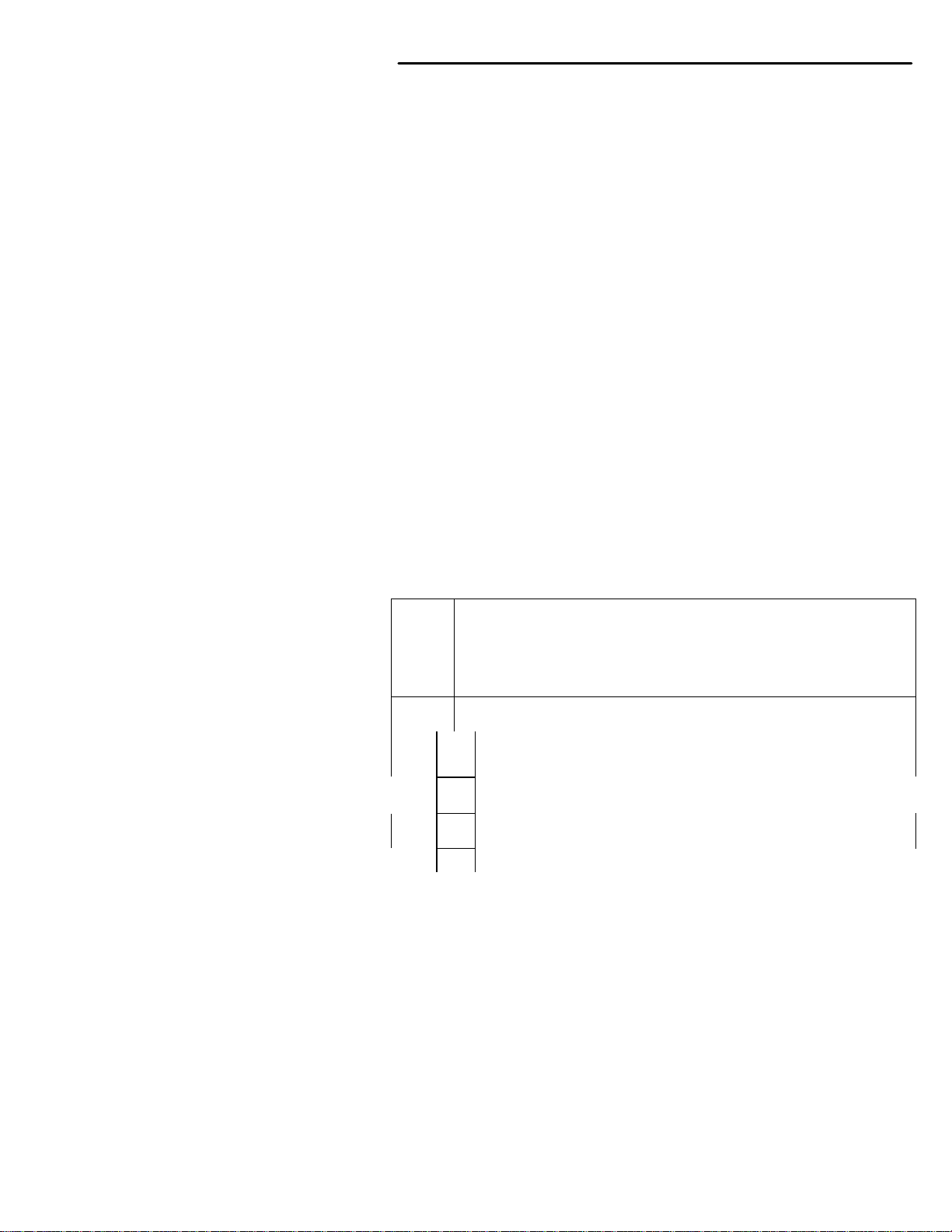
Reading Capacitors:
Unlike resistors, capacitors no longer use a color code for value identification.
Instead, the value, or a 3-number code, is printed on the body.
Super CW Filter Kit
in ascending order of value. Small-value capacitors are characterized in
pico-Farads), while larger values are labeled in uF (or micro-Farads).
monolithic and disc-ceramic capacitors are marked with a three-number code.
multiplier (same as resistors).
devices and must be oriented correctly during installation. If yo
shorter than the positive lead.
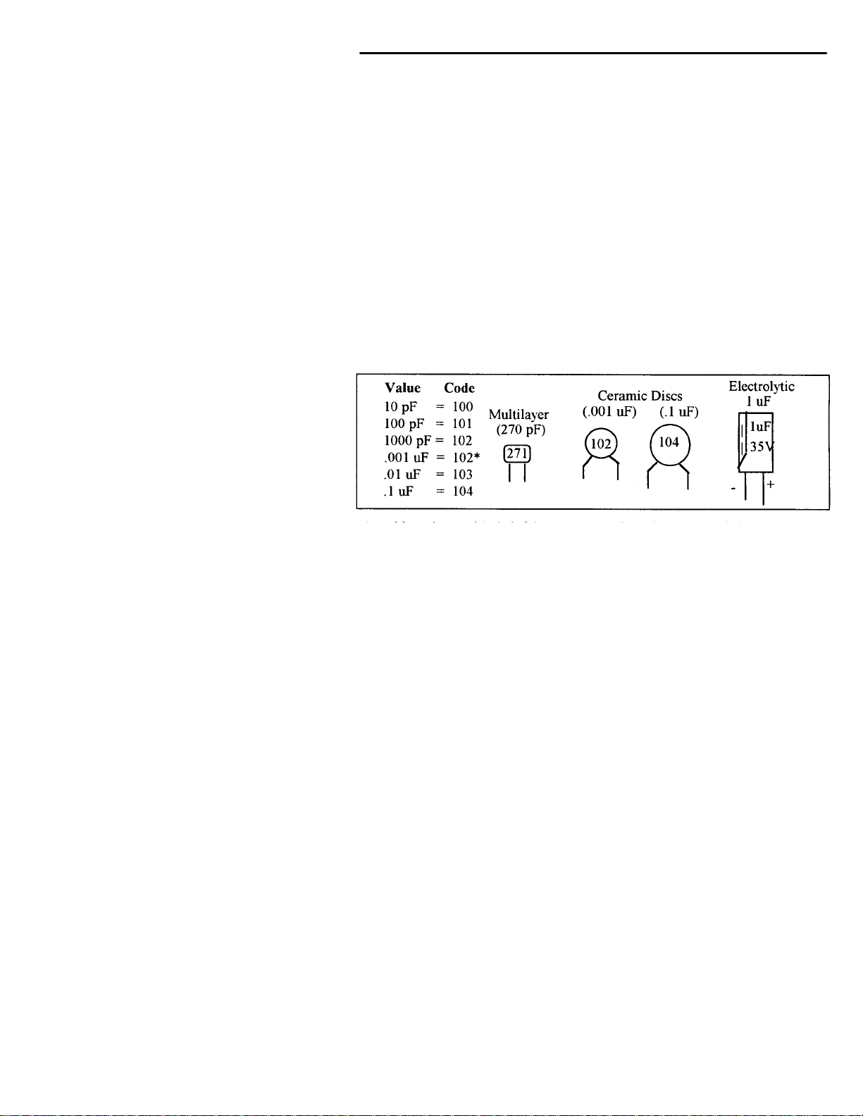
Diodes:
Diodes are also polarized devices that must be installed correctly. Always
for the banded or cathode end when installing, and follow instructions carefully.
Page 7
VEC-821 K Instruction Manual Super CW Filter Kit
Transistors:
If transistors are installed incorrectly, damage may result when power is
Many
current voltage regulators also use this type
with
indicated by
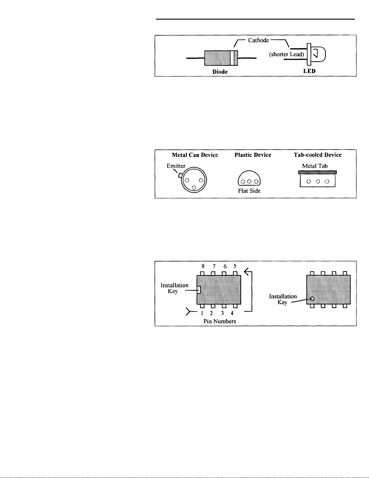
Integrated Circuits:
end
board and
1C pin
always start
around the device,
applied. Transistors in metal cases have a small tab near the emitter lead to
identify correct positioning. Semiconductors housed in small plastic cases (TO-
92) have an easily-identified flat side to identify mounting orientation.
specialized diodes and lowpackaging. Larger plasti c transistors and voltage regulators use a case backed
a prominent metal tab to dissipate heat (T-220). Here orientation is
the positioning of the cooling tab.
Proper IC positioning is indicated by a dot or square marking located on one
of the device. A corresponding mark will be silk-screened on the PC
printed on the kit's parts-placement diagram. To identify specific
numbers for testing purposes, see the diagram below. Pin numbers
at the keyed end of the case and progress counter-clockwise
as shown:
Page 8

VEC-821K Instruction Manual
Super CW Filter Kit
Q Qty Part Description
Designation
PARTS LIST
Your kit should contain all of the parts listed below. Please go through the
parts bag to identify and inventory each item on the checklist before you start
building. If any parts are missing or damaged, refer to the warranty section of this
manual for replacement instructions. If you can't positively identify an
unfamiliar item in the bag on the basis of the information given, set it aside until
all other items are checked off. You may then be able to identify it by process of
elimination. Finally, your kit will go together more smoothly if parts are organized
by type and arranged by value ahead of time. Us e this inventory as an opportunity
to sort and arrange parts so you can identify and find them quickly.
0 1 2.7 ohm resistor (red-violet-gold) R17
0 1 5.6 ohm, 1/2 watt resistor (green-blue-gold) R19
0 1 1K ohm resistor (brown-black-red) R2
0 1 1.8K ohm resistor (brown-gray-red) R1
0 6 24.3K* ohm resistor (red-yellow-orange-red) R5,R8,R10,R13,
R14,R15
0 1 91K ohm resistor (white-brown-orange) R3
0 4 681K* resistor (blue-gray-brown-orange) R4,R7,R11,R18
0 4 1.82M* ohm resistor (brown-gray-red-yellow) R6,R9,R12,R16
0 6 .1uF disc ceramic capacitor (104 or 104Z) C2,C3,C4,C5,C6,
C7
0 1 .01uF disc ceramic capacitor (1032) C8
0 8 1000 pF poly capacitor (1000J) C12,C13,C14,C15,
C16,C17,C18,C19
0 2 470uF electrolytic capacitor (470uF) C1,C9
0 2 10 uF electrolytic capacitor radial (10uf) C10,C11
0 2 1N34 germanium diode (1N34) D1,D2
0 2 LM747 Op Amp IC U1,U2
0 1 LM380 Audio Amplifier (LM380) U3
0 3 14 pin IC sockets For U1,U2,U3
0 1 Rotary Switch SW1
1 3/8-32 Hex Nut For SW1
0 1 Thin Flat Steel Washer For S W l
0 4 6" insulated wires For Circuit wiring
0 1 9-volt battery snap GND, PWR
0 1 PC board VEC-821K
0 1 Owner's Manual
* These parts have a 1% tolerance. The fifth color band on these components will be BROWN,
specifying a 1% tolerance.
Page 9

Super CWV Filter Kit
Figure 1
kit
warranty printed on the inside cover of this manual. Also, read thro
ugh the
assembly instructions to make sure the kit does not exceed your skill level.
returnable. Finally, if you
haven't already done so, please verify that all parts listed in the inventory are
for
Note that part designators, such as R1, C3, etc., appear on a silk
screened
corresponds with the parts placement page in the manual. All parts will be
minute questions about what you need to build your kit, please
now,
VEC-821 K Instruction Manual
PARTS PLACEMENT DIAGRAM
STEP-BY-STEP ASSEMBLY
Before assembling your kit, please take time to read and understand the VEC
Once you begin construction, your kit will be non-
included. If anything is missing or broken, refer to the warranty instructions
replacing missing or damaged parts.
-
legend on the component-mounting side of the printed circuit board. This
inserted on the silk-screen side of the board.
If you have last-
refer back to the section titled "Tools and Supplies". If you're ready to begin
here we go!
Page 10

VEC-821K Instruction Manual
The directions use two sets of check boxes. Check one when a step is complete
istor body rests against
Super CW Filter Kit
and use the other for double-checking your work before operation.
Phase 1:
• 0 1. Locate resistor R1. This is 1.8K resistor (brown-gray-red).
Carefully bend the leads close to the resistor body to form right-angles (see
following diagram).
I f .4" ->I
• 0 2. Insert R1 into its mounting holes so the resistor body rests against the
board. Solder in place and trim the leads.
• 0 3. Locate resistor R2. This is 1K resistor (brown-black-red). Carefully bend
the leads close to the resistor body as in Step #1.
• 0 4. Insert R2 into its mounting holes so the resistor body rests against the
board. Solder in place and trim the leads.
• 0 5. Locate resistor R3. This is 91K resistor (white-brown-orange). Carefully
bend the leads close to the resistor body as in Step # 1.
• 0 6. Insert R3 into its mounting holes so the resistor body rests against the
board. Solder in place and trim the leads.
• 0 7. Locate resistor R4. This is 681K resistor (blue-gray-brown-orange).
Carefully bend the leads close to the resistor body as in Step # 1.
• 0 8. Insert R4 into its mounting holes so the resistor body rests against the
board. Solder in place and trim the leads.
• 0 9. Locate resistor R7. This is 681K resistor (blue-gray-brown-orange).
Carefully bend the leads close to the resistor body as in Step #1.
• 010. Insert R7 into its mounting holes so the resistor body rests against the
board. Solder in place and trim the leads.
• 011. Locate resistor R1 I. This is 681K resistor (blue-gray-brown-orange).
Carefully bend the leads close to the resistor body as in Step #1.
• 012. Insert R1 l into its mounting holes so the res
the board. Solder in place and trim the leads.
• 013. Locate resistor R18. This is 681K resistor (blue-gray-brown-orange).
Carefully bend the leads close to the resistor body as in Step #1.
Page 11

VEC-821 K Instruction Manual
Super CW
Filter Kit
• 014. Insert R18 into its mounting holes so the resistor body rests against the
board. Solder in place and trim the leads.
• 017. Locate resistor R5. This is 24.3K resistor (red-yellow-orange-red).
Carefully bend the leads close to the resistor body as in Step #1.
• 018. Insert R5 into its mounting holes so the resistor body rests against the
board. Solder in place and trim the leads.
• 019. Locate resistor R8. This is 24.3K resistor (red-yellow-orange-red).
Carefully bend the leads close to the resistor body as in Step #1.
• 020. Insert R8 into its mounting holes so the resistor body rests against the
board. Solder in place and trim the leads.
• 021. Locate resistor R10. This is 24.3K resistor (red-yellow-orange-red).
Carefully bend the leads close to the resistor body as in Step #1.
• 022. Insert R10 into its mounting holes so the resistor body rests against the
board. Solder in place and trim the leads.
• 023. Locate resistor R13. This is 24.3K resistor (red-yellow-orange-red).
Carefully bend the leads close to the resistor body as in Step #1.
• 024. Insert R13 into its mounting holes so the resistor body rests against the
board. Solder in place and trim the leads.
• 025. Locate resistor R14. This is 24.3K resistor (red-yellow-orange-red).
Carefully bend the leads close to the resistor body as in Step #1.
• 026. Insert R14 into its mounting holes so the resistor body rests against the
board. Solder in place and trim the leads.
• 027. Locate resistor R15 This is 24.3K resistor (red-yellow-orange-red).
Carefully bend the leads close to the resistor body as in Step #1.
• 028. Insert R15 into its mounting holes so the resistor body rests against the
board. Solder in place and trim the leads.
• 029. Locate resistor R6. This is 1.82M resistor (brown-gray-red-yellow).
Carefully bend the leads close to the resistor body as in Step #1.
• 030. Insert R6 into its mounting holes so the resistor body rests against the
board. Solder in place and trim the leads.
• 031. Locate resistor R9. This is 1.82M resistor (brown-gray-red-yellow).
Carefully bend the leads close to the resistor body as in Step #1.
• 032. Insert R9 into its mounting holes so the resistor body rests against the
board. Solder in place and trim the leads.
Page 12

VEC-821K Instruction Manual
Super CW F
ilter Kit
Now that you have finished Phase 1, you may want to take a few minutes to
double check your work. There are two phases to go and quite a few additional
e
Now that you have finished your double check it is time to move on.
• 033. Locate resistor R12. This is 1.82M resistor (brown-gray-red-yellow).
Carefully bend the leads close to the resistor body as in Step #1.
• 034. Insert R12 into its mounting holes so the resistor body rests against
the board. Solder in place and trim the leads.
• 035. Locate resistor R16. This is 1.82M resistor (brown-gray-red-yellow).
Carefully bend the leads close to the resistor body as in Step # 1.
• 036. Insert R16 into its mounting holes so the resistor body rests against
the board. Solder in place and trim the leads.
• 037. Locate resistor R17. This is 2.7 ohm resistor (red-violet-gold).
Carefully bend the leads close to the resistor body as in Step #1.
• 038. Insert R17 into its mounting holes so the resistor body rests against
the board. Solder in place and trim the leads.
• 039. Locate resistor R19. This is 5.6 ohm resistor (green-blue-gold).
Carefully bend the leads close to the resistor body as in Step # 1.
• 040. Insert R19 into its mounting holes so the resistor body rests against
the board. Solder in place and trim the leads.
parts to be installed; making the board more crowded and hard to find th
different components.
Phase 2:
Important Note: Capacitors C12-C19 are made of a polystyrene type material.
Avoid overheating these components when soldering to prevent melting the
capacitor body.
0 0 1. Locate capacitor C12 (1000pF). The is a polystyrene capacitor and
will be marked with a "1000J" on the body. (actual value in pF).
0 0 2. Mount C12 and solder both leads in place, making sure the capacitor
remains seated. Remove excess leads on the bottom side of the board
with diagonal cutters.
0 0 3. Locate capacitor C13 (1000pF). The is a polystyrene capacitor and
will be marked with a "1000J" on the body. (actual value in pF).
Page 13

Page 14

VEC-821K Instruction Manual
Super CW Filter
Kit
4. Mount C 13 and solder both leads in place, making sure the capacitor
remains seated. Remove excess leads on the bottom side of the board
will
0 6. Mount C 14 and solder both leads in place, making sure the capacitor
remains seated. Remove excess leads on the bottom side of the board
will
0 8. Mount C15 and solder both leads in place, making sure the capacitor
remains seated. Remove excess leads on the bottom side of the board
will
010. Mount C16 and solder both leads in place, making sure the capacitor
leads on the bottom side of the board
ure the capacitor
remains seated. Remove excess leads on the bottom side of the board
unt C 18 and solder both leads in place, making sure the capacitor
remains seated. Remove excess leads on the bottom side of the board
016. Mount C19 and solder both leads in place, making sure the capacitor
remains seated. Remove excess leads on the bottom side of the board
• 0
with diagonal cutters.
• 0 5. Locate capacitor C14 (1000pF). The is a polystyrene capacitor and
be mar ked with a "1000J" on the body. (actual value in pF).
•
with diagonal cutters.
• 0 7. Locate capacitor C15 (1000pF ). The is a polystyrene capacitor and
be marked with a "1000J' on the body. (actual value in pF).
•
with diagonal cutters.
• 0 9. Locate capacitor C16 (1000pF). The is a polystyrene capacitor and
be marked with a "1000J" on the body. (actual value in pF).
•
remains seated. Remove excess
with diagonal cutters.
• 011. Locate capacitor C17 (1000pF). The is a polystyrene capacitor and will
be marked with a "1000J" on the body. (actual value in pF).
• 012. Mount C17 and solder both leads in place, making s
with diagonal cutters.
• 013. Locate capacitor C18 (1000pF). The is a polystyrene capacitor and will
be marked with a "1000J" on the body. (actual value in pF).
• 014. Mo
with diagonal cutters.
• 015. Locate capacitor C19 (1000pF). The is a polystyrene capacitor and will
be marked with a "1000J" on the body. (actual value in pF).
•
with diagonal cutters.
• 017. Locate capacitor C2 (.1uF). This is a disc ceramic type capacitor and
will be marked "104" or "104Z" (actual value in uF). Carefully
Page 15

VEC-821K Instruction Manual
Super CW Filter Kit
will
install C7,
then solder in
will
install C3,
then solder in place
will
install C4,
then solder in
will
install C6,
then solder in
will
install C5,
then solder in
and
install
then solder in
his is a germanium diode and is made from a
clear glass type material. This part will have a band on one end indicating
Remember diodes are polarity sensitive devices that must be installed correctly.
installing, and follow instructions
0 25. Insert D I into its mounting holes so the diode body rests against the
board. Be sure to observe the circuit marking indicating the cathode.
install C2, be sure not to chip the ceramic material. Once installed, then
solder in place and trim the leads.
• 018. Locate capacitor C7 (.1uF). This is a disc ceramic type capacitor and
be marked "104" or "104Z" (actual value in uF). Carefully
be sure not to chip the ceramic material. Once installed,
place and trim the leads.
• 019. Locate capacitor C3 (.1uF). This is a disc ceramic type capacitor and
be marked "104" or "104Z" (actual value in uF). Carefully
be sure not to chip the ceramic material. Once installed,
and trim the leads.
• 020. Locate capacitor C4 (.1uF). This is a disc ceramic type capacitor and
be marked "104" or "104Z" (actual value in uF). Carefully
be sure not to chip the ceramic material. Once installed,
place and trim the leads.
• 021. Locate capacitor C6 (.1uF). This is a disc ceramic type capacitor and
be marked "104" or "104Z" (actual value in uF). Carefully
be sure not to chip the ceramic material. Once installed,
place and trim the leads.
• 022. Locate capacitor C5 (.1uF). This is a disc ceramic type capacitor and
be marked "104" or "104Z" (actual value in uF). Carefully
be sure not to chip the ceramic material. Once installed,
place and trim the leads.
• 023. Locate capacitor C8 (.01uF). This is a disc ceramic type capacitor
will be marked "103" or "103Z" (actual value in uF). Carefully
C8, be sure not to chip the ceramic material. Once installed,
place and trim the leads.
• 024. Locate diode D1 (1N34). T
the cathode end of the diode.
Always look for the banded or cathode end when
carefully.
•
Solder in place and trim the leads.
Page 16

VEC-821K Instruction Manual
Super CW Filter Kit
from
end
s mounting holes so the diode body rests against the
board. Be sure to observe the circuit marking indicating the cathode.
Now that you have finished Phase 2, you may want to take a few minutes to
Now that you have finished your double check it is time to move on.
and will
C10, be sure
to orient the negative end of the capacitor properly. Please refer to
correct orientation
(10uF). This is an electrolytic type capacitor and
will be marked "10uF" (actual value in uF). Carefully install C11, be
sure to orient the negative end of the capacitor properly. Please refer
trim the
0 4. Install the 1C socket at the U1 location on the circuit board. Be
Placement"
0 5. Carefully bend over the four corner pins of the socket against the
e circuit board. Be
Placement"
0 8. Carefully bend over the four corner pins of the socket against the
• 026. Locate diode D2 (1N34). This is a germanium diode and is made
a clear glass type material. This part will have a band on one
indicating the cathode end of the diode.
• 027. Insert D2 into it
Solder in place and trim the leads.
double check your work. There is still one more phase to go.
Phase 3:
• 0 1. Locate capacitor C10 (10uF). This is an electrolytic type capacitor
be marked "10uF" (actual value in uF). Carefully install
the section titled, "Parts Placement", Figure 1 for
of C10. Once installed, then solder in place and trim the excess leads.
• 0 2. Locate capacitor C l 1
to the section titled, "Parts Placement", Figure 1 for correct
orientation of C 11. Once installed, then solder in place and
excess leads.
• 0 3. Locate (1) 14 pin 1C socket.
•
careful to orient the socket correctly according to the "Parts
section Figure 1.
•
solder pads on the solder side of the board. Solder in place.
• 0 6. Locate another 14 pin IC socket.
• 0 7. Install the IC socket at the U2 location on th
careful to orient the socket correctly according to the "Parts
section Figure 1.
•
solder pads on the solder side of the board. Solder in place.
• 0 9. Locate the remaining 14 pin 1C socket.
Page 17

VEC-821K Instruction Manual
Super CW Filter Kit
010. Install the 1C socket at the U3 location on the circuit board. Be
careful to orient the socket correctly according to the "Parts Placement"
11. Carefully bend over the four corner pins of the socket against the
012. Locate capacitor C 1 (470uF). This is an electrolytic type capacitor
C1,
Please
refer to the section titled, "Parts Placement", Figure 1 for correct
trim the
and
C9, be
Please
correct
trim the
014. Locate the rotary switch, SW1. Insert the pins on the underside of the
come
switch is
to the circuit
017. Take one 3" piece of insulated wire and insert one end into the hole
the
hole
trim the
019. Take another 3" piece of insulated wire and insert one end into the
trim
•
section Figure 1.
• 0
solder pads on the solder side of the board. Solder in place.
•
and will be marked "470uF" (actual value in uF). Carefully install
be sure to orient the negative side of the capacitor properly.
orientation of C1. Once installed, then solder in place and
excess leads.
• 013. Locate capacitor C9 (470uF). This is an electrolytic type capacitor
will be marked "470uF" (actual value in uF). Carefully install
sure to orient the negative end of the capacitor properly.
refer to the section titled, "Parts Placement", Figure 1 for
orientation of C9. Once installed, then solder in place and
excess leads.
•
switch into the circuit board holes. Ensure that all of the pins
through the underside of the circuit board. Ensure that the
mounted flush to the board and the switch shaft is parallel
board. Solder in place.
• 015. Prepare eight (8) 3" wires, by cutting all four (4) 6" wires provided in the
kit.
• 016. Using the wire strippers, remove a 1/4" piece of insulation from each of
the 8 pieces of insulated wire.
•
silk-screened INPUT on the circuit board. Solder in place and trim
excess lead.
• 018. Take another 3" piece of insulated wire and insert one end into the
silk-screened GND2 on the circuit board. Solder in place and
excess lead.
•
hole silk-screened GND3 on the circuit board. Solder in place and
the excess lead.
Page 18

VEC-821K Instruction Manual
Super CW Filter Kit
hole
trim the
022. Insert the RED wire of the battery snap into the hole on the circuit
he hole on the
024. Locate both LM747 op amp integrated circuits. Insert them into is
sockets for U1 and U2. Please refer to the "Parts Placement" section,
sure not to bend any of the pins
025. Locate the LM380 audio amplifier integrated circuit. Insert it into is
or
underneath the is
earned break! You
parts are to be used when the
circuit is installed in an enclosure, so do not discard them. When you come
quality control)
inspection. This will help you find inadvertent assembly errors that might
prevent the filter from working or cause damage to sensitive parts. Follow this
Start at
bright light for a better view. All joints should be smooth and shiny,
-
If you find a construction error and need to remove a part or two, it will be
easier if you have the right tools. One very convenient item for freeing
• 020. Take another 3" piece of insulated wire and insert one end into the
silk-screened SPKR on the circuit board. Solder in place and
excess lead.
• 021. Locate the battery snap.
•
board labeled, PWR. Solder in place and trim the lead.
• 023. Insert the BLACK wire of the battery snap into t
circuit board labeled, GND. Solder in place and trim the lead.
•
Figure 1 for proper orientation. Be
underneath the is body, and that all pins are inserted into the socket.
•
socket for U3. Please refer to the "Parts Placement" section, Figure 1 f
proper orientation. Be sure not to bend any of the pins
body, and that all pins are inserted into the socket.
At this point, your kit is finished and it's time to take a wellshould have one washer and nut left. These
back, be sure to give your work a close "quality control" inspection.
PC Board Inspection:
Before applying power to your kit, give it a thorough QC (
procedure:
• Compare parts locations against the parts-placement diagram. Was each part
installed where it is supposed to be? Was the correct value used?
one side of the board and work your way across in an organized pattern.
• Inspect the solder side of the board for cold-solder joints and solder bridges
between tracks or pads. Use a magnifying glass to obtain a clear view of
the track area. If you suspect a solder bridge, hold the board in front of a
indicating good solder wetting and flow. Resolder any beaded or dull
appearing connections.
Page 19

VEC-821K Instruction Manual
Super CW Filter kit
solder sucker". This consists of a suction bulb or a
spring loaded vacuum pump that draws molten solder away from the pad and
lead. Alternatively, you may use a special copper braid called "solder wick"
your local Radio Shack or
electronics supply house). If you suspect you've damaged a component during
Finally, rosin flux can absorb moisture, which may cause a problem for some
remove flux, use isopropyl alcohol (or 95% grain
alcohol) and an old toothbrush. Apply a generous amount of alcohol with the
of
allow
CAUTION:
ALCOHOL IS HIGHLY FLAMMABLE AND MUST BE USED
WITH
AND AVOID
TO DO THIS
Now that assembly and inspection
is completed, you're ready to begin the
821K is with a calibrated audio signal generator
all
components are installed correctly and in the proper places, the center
800 hertz. The filter has three
switch selectable selectivity cutoff points, 80, 110, and 180 hertz. The switch
ft to right are BYPASS, 180, 110, and 80. The 80
hertz cutoff is the fourth switch position from the left and is the narrowest filter
cutoff, while the 180 hertz cutoff is the second position from the left and is the
widest filter cutoff.
821K is working, or not, is to
cutoff
ht band pile up, then
selectivity
e
110 or 180 filter cutoffs. However, in these positions the filter will let slightly
soldered-in parts is a "
(solder suckers and solder wick are both available at
removal, better to replace it than risk reusing it!
electronic equipment. To
toothbrush and scrub gently. Once the flux has fully dissolved, blot the bottom
the board dry with an untreated tissue. Give it a final alcohol wash, and
to dry thoroughly.
ADEQUATE VENTILATION! USE SAFETY GOGGLES,
PROLONGED SKIN CONTACT. IT'S ALSO BEST
OUTDOORS.
testing and alignment phase of construction.
TESTING AND ALIGNMENT
The best way to test the VECand oscilloscope. However, VEC-821K does not require any alignment. If
frequency of the filter will be between 750-
positions on SW1 from le
Probably the best method of seeing if the VEClisten to some "on the air" CW signals. Then using SW1, select the filter
position that best cleans up the signal being received.
If you are trying the pick out one signal out of a very tig
try using the 80 hertz cutoff. The 80 hertz cutoff provides the highest
and will greatly help you in "pulling out" those hard to get signals.
If the CW signal you are receiving is noisy with some static, then try either th
more noise through, but in some cases this may be desirable. The best way to
Page 20

see which position works the best is to tr
y it. This way you can really hear what
the
best in
a
volt
821 K with a communications
receiver or scanner. A BFO, or Beat Frequency Oscillator, or a Fine Tuning
821K
The filter requires audio from the external speaker or headphones output of the
receiver or scanner. Apply the positive side of the audio signal to the insulated
wire connected to the location on the circuit labele
negative
on the
section,
Next, con
lead of the external speaker to the end of the
insulated wire connected to the location on the circuit board labeled SPKR.
GND
Figure 1
Next, turn the receiver volume all the way down, then clip the 9
volt battery to
r up
slightly so you can hear the received signals on the external speaker. The
signal you are listening to is the "raw" or "unfiltered" signal. Using the tuning
VEC-821K Instruction Manual
filter is doing for the received signal, and which switch position works the
different band conditions.
Super CW Filter Kit
OPERATING INSTRUCTIONS
You may use the VEC-821K with any communications receiver or scanner with
BFO, (Beat Frequency Oscillator). You can also use the VEC-821K with and hamradio transceiver in either LSB or CW mode. The VEC-821K requires a 9battery power source, or any 9-18 volt DC source.
There are a few items that you will need to operate the VEC-821 K. We have
provided a list of these items below for your convenience.
• Communications Receiver, scanner, or Ham Radio transceiver with proper
cables.
• 9-Volt transistor radio battery
• External speaker with clip leads
Receiver or Scanner Operation
As previously mentioned you can use the VEC-
control will assist you in fine tuning the received CW signal to the VECcenter frequency. The center frequency of the filter being 750-800 hertz.
d INPUT. Apply the
side of the audio signal to the insulated wire connected' to the location
circuit board labeled GND2. Please refer to the "Parts Placement"
Figure 1 for the location of both points on the circuit board.
nect the POSITIVE
Connect the NEGATIVE lead of the external speaker to the point labeled
on the circuit board. Again please refer to the "Parts Placement" section
for the location of the point labeled GND on the circuit board.
-
battery snap. Set SW1 to the far left position. Now turn the receive
knob on the radio, find a CW signal. A good place to find CW signals is in the
Page 21

VEC-821K Ins
truction Manual
Super CW Filter Kit
Amateur Radio bands. Once you find a CW signal, switch SW1 to the 110
the
fore. You can
now fine tune the radio tuning knob for the best received signal. If using a
communications receiver or scanner with a BFO control, use this control to fine
tune the received CW signal. If the receiver or scanner you are using does not
BFO control, it will be very difficult trying to tune the signal in
properly. If the signal you are trying to receive is in a "pile up", then try the 80
mateur Radio transceiver is basically the same, but you
would use either LSB, (Lower Side Band) or CW mode. All other connections
are
generally
all
1.
Most of the time there will be a part that is not installed or not installed
rly, a wrong value part in place of another, or a broken part. A close
problem
with bro
be caused by
more
circuit
the part with your fingers. If the part is bad, it could be HOT
en
wires could cause this problem.
filter cutoff. The 110 position is the third from the left. When you switch to
110 cutoff, you will notice that the signal sounds cleaner than be
have a
hertz filter cutoff. Then fine tune the receiver to "pull out" the desired signal.
Operation with an A
the same.
IN CASE OF DIFFICULTY
No Signal Filtering:
A newly constructed filter that fails to work upon initial power up,
requires a very close and careful inspection of all work. Please go back through
steps of assembly and inspection, referring to the "Parts Placement" Figure
prope
inspection at this point may reveal some accidental mistake(s).
Intermittent Filter Operation:
A filter that operates intermittently may have poor solder connections, a
ken wires, or a low voltage power source. Self-oscillation may
a defective U1, U2, or U3. Also, check for dirty or intermittent switch operation.
Filter Stops Filtering:
A working filter that fails "in -service" generally indicates a failure of one or
of the integrated circuits U1, U2, or U3. If you suspect a bad integrated
then do not touch
and could cause a serious burn. The supply voltage (9-volt battery) and/or brok
Page 22

VEC-821K Instruction Manual
Super CW Filter Kit
No speaker audio can be a symptom of a bad S W 1, a broken wire or a bad C9.
the
could
form
narrow
ringing,
800
821K Super
CW Filter Kit. The matching enclosure is an all metal box which includes
knobs, hardware, decals, and rubber feet. The Vectronics model number for the
No Speaker Audio:
Check the voltage from the 9-volt battery. A broken wire at the audio input to
filter could attribute to no speaker audio. The audio amplifier chip (U3)
also be defective.
If technical assistance or factory repair is desired, please refer to the warranty
instructions on the inside front cover.
THEORY OF OPERATION AND SPECIFICATIONS
Circuit Description:
The VEC-821K uses two UA747 operational amplifier integrated circuits to
four low Q cascaded stages with no insertion loss. This results in a very
bandwidth and extremely high skirt rejection with minimal audible
making good signal copying possible. The center frequency is between 750hertz. The filter also has an LM380 Audio Amplifier which can drive
an 8 ohm speaker or headphones.
Specifications:
Bandwidth: .........................................80 Hz, 110 Hz, 180 Hz (switch selectabl e)
Skirt Rejection: ....................................At least 60dB down 1 octave from center
frequency for 80 Hz. bandwidth.
Center Frequency: ..............................750-800 Hz
Insertion Loss: ...................................None
Power Required: ................................9-volts DC; 9-volt battery
PCB Dimensions: ...............................2" x 3"
ENCLOSURE
Vectronics has designed a matching enclosure just for your VEC-
matching enclosure is VEC-82 1KC.
 Loading...