

Page 1

IMPORTANT WARRANTY INFORMATION! PLEASE READ
p
Return Policy on kits When Not Purchased Directly From Vectronics: Before continuing any
further with your VEC kit check with your Dealer about their return policy. If your Dealer
allows returns, your kit must be returned
Return Policy on kits VVhen Purchased Directly From Vectronics: Your VEC kit may be
returned to the factory
once you begin installing and sold ering parts, you es sentia lly take over the role of th e device's
manufacturer. From this p oint on, neith er Vect ronics nor its d ealers can reas onab ly be h eld
accountable for the quality or the outcome of your work. Because of this, Vectronics cannot
accept return of any kit-in-progress or completed work as a warranty item for any reason
whatsoever. If you are a new or inexperienced kit builder, we urge you to read the manual
carefully and determine whether or not you're ready to take on the job. If you wish to change
your mind and return your kit, you may--but you must do it
within ten (10) working days of the time it a rrives .
in its pre-assembled condition only.
before you
begin construction.
The reason for this st ipulation i s,
before you
begin construction, and
Vectronics Warrants: Your kit contains each item s
Missing Parts: If you determine, during your pre-construction inventory, that any part is
missing, please contact Vectronics and we'll send the missing item to you free of charge.
However,
the marking on one of the other items provided with th e kit. Also, make certain an a lternative
part hasn't been substituted for the item you're missing. If a specific part i s no longer available,
or if Engineering has d etermined that an alternative component is more suitable, Vectronics
reserves the right to make substitutions at any time. In most ca ses, these chan ges will be clea rly
noted in an addendum to the manua l.
Defective Parts: Today's electronic parts ar e physically and electrica lly resilient, and defecti ve
components are rare. However, if you discover an it em during your pre-c onstruction in ventory
that's obviously broken or unserviceable, we'll rep lace it. Just return th e part to Vectronics at
the address below accompanied with an explanation. Upon receipt, we'll test it. If it's defectiv e
and appears unused, we'll ship you a new one right away at no charge.
Missing or Defective Parts After You Begin Assembly: Parts and materials lost or damaged
before you
after construction begins
supplied with VEC kits are relatively inexpensive and Vectronics can replace them for a
reasonable charge. Simp ly c ontact t he factory with a complet e d esc ription. We'll p roces s you r
order quickly and get you back on track.
Factory Repair After You Begin Assembly:
contact Vectronics,
are not covered und er th e t erms of this warran t y. However, most pa rts
please look ca reful ly
Kits-in progress and completed kits are spec ifically
excluded from coverage by the Vect ronics warr anty.
technicians are available t o evaluat e and r epair ma lfunctionin g kits for a minimu m ser vice f ee
of $18.00 (1/2
qualify for repair service, your kit must be fully complet ed, unmodi fied, and the p rinted ci rcuit
board assembled using rosin-core solder. In the event your repair will require more than an
hour to fix (or $36.00, subj ect t o ch ange), our technici ans wi ll contact you in ad van ce by
telephone before performin g the work. Def ectiv e units sh ould be shipp ed p repaid t o:
hour rate) plus $7.00 shipping and hand ling (p rices subj ect to chan ge). To
ecified in the parts list.
to confirm you haven't misread
However, as a s ervic e t o cust omers,
When shipping, pack your kit well and include the minimum payment plus shipping and
handling charges ($25.00 tota l). No work can b e perfo rmed with out p re-p ayment. Also, p r ovide
a valid UPS return address and a day time phone number where you may be reached.
Page 2
Page 3

VEC-820
K I
nstruction Manual CW Filte
g
r
INTRODUCTION
Thank you for purchasing the VEC-820K CW Filter kit. The VEC-820K consists
of a four stage, switch selectable band pass CW filter, using selected co mponent s
that will make "cleaning up" CW signals effortless and easy. With the VEC820K you bring up any hard to hear signal out of a "band pile up," for easy
listening, or get rid of unwanted, annoying signals. The VEC-820K also features
a headphone output that will allow the use of standard monoral headphones.
Although physically small in size, the VEC-820K is high on performance and
reliability. The VEC-820K is powered from a 9-volt transistor radio batterv.
Construction Area: Kit construction requires a clean, smooth, a nd well-ighted
area where you can easily organize and handle small parts without losing them.
An inexpensive sheet of white poster board makes an excellent construction
surface. while providing protection for the underlying table or desk. Welldiffused overhead lighting is a plus, and a supplemental highintensity desk lamp
will prove especially helpful for close-up work. Safety is an important
consideration. Be sure to use a suitable high-temperature stand for your soldering
iron. and keep the work area free of combustible clutter.
Universal Kit-building Tools: Although your particular kit may require
additional items to complete, virtually all construction pr ojects require a work
area outfitted with the followin
tools and supplies:
Page 4

-
y
q
g
BEFORE YOU START BUILDING
Experience shows there are
and
our kit will probably work on the first try! Here's wha t they are:
1. Installing the Wrong Part: It always pays to double-check each step. A 1K and
a 10K resistor may look
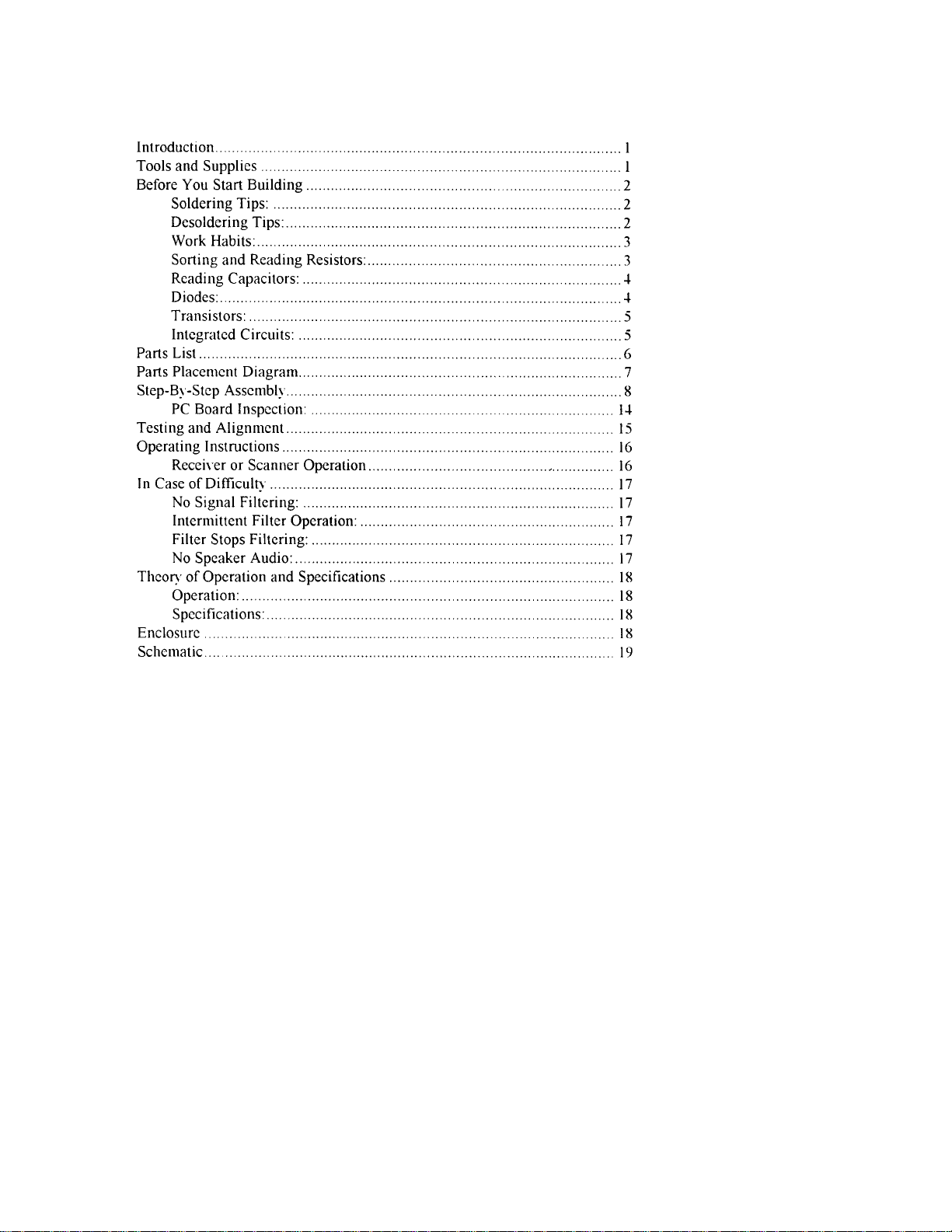
an electronic circuit! Same for capacitors--a device marked 102 (or.001 uF)
may have very different operating characteristics from one marked 103 (or
.01uF
2. Installing Parts Backwards: Always check the polarity of electrolytic
capacitors to make sure the positive (+) lead goes in the (+) hole on the
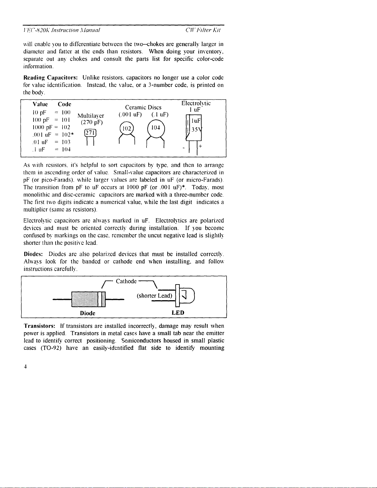
circuit board. Transistors have a flat side or emitter tab to help you identify
the correct mounting position. ICs have a notch or dot at one end indicating
the correct direction of insertion. Diodes have a banded end indicating
correct polarity. Always double-check--especially before applying power to
the circuit!
3. Faulty Solder Connections: Inspect for cold-solder j oints and solder bridges.
Cold solder joints happen when you don't fully heat the connection--or when
metallic corrosion and oxide contaminate a component lead or pad. Solder
bridges form when a trail of excess solder shorts pads or tracks together (see
Solder Tips below).
jour common mistakes
almost
the same, but they may act very differently in
builders make. Avoid these.
4. Omitting or Misreading a Part: This is easier to do than you might think!
Always double-check to make sure you completed each step in an assembly
se
uence.
Soldering Tips:
professional soldering. Before you install and solder each part, inspect leads or
pins for oxidation. If the metal surface is dull, sand with fine emery paper until
shiny. Also, clean the oxidation and excess solder from the soldering iron tip to
allow maximum heat transfer. Allow the tip of your iron to contact both the lead
and pad for about one second (count "one-thousand-one") before feeding solder
to the connection. Surfaces must become hot enough for solder to flow smoothly.
Feed solder to the opposite side of the lead from your iro n tip--solder will wick
around the lead toward the tip, wetting all exposed surfaces. Apply solder
sparingly, and do not touch solder directl y to the hot iron tip to promote rapid
melting.
Desoldering Tips: If you make a mistake and need to remove a part, follow these
instructions carefully! First, grasp the component with a pair of hemostats or
needle-nose pliers. Heat the pad beneath the lead you intend to extract, and pull
ently. The lead should come out. Repeat for the other lead.
Cleanliness
and good
heat distribution
are the two secrets of
Page 5
Page 6
VEC-820K Instruction Manual CW Filter Kit
orientation. Many specialized diode s and low-curre nt voltag e re gulators a lso use
this type packaging. Larger plastic transistors and voltage regulators use a case
backed with a prominent metal tab to dissipate heat (T-220). Here
orientation is indicated by the positioning of the cooling tab.
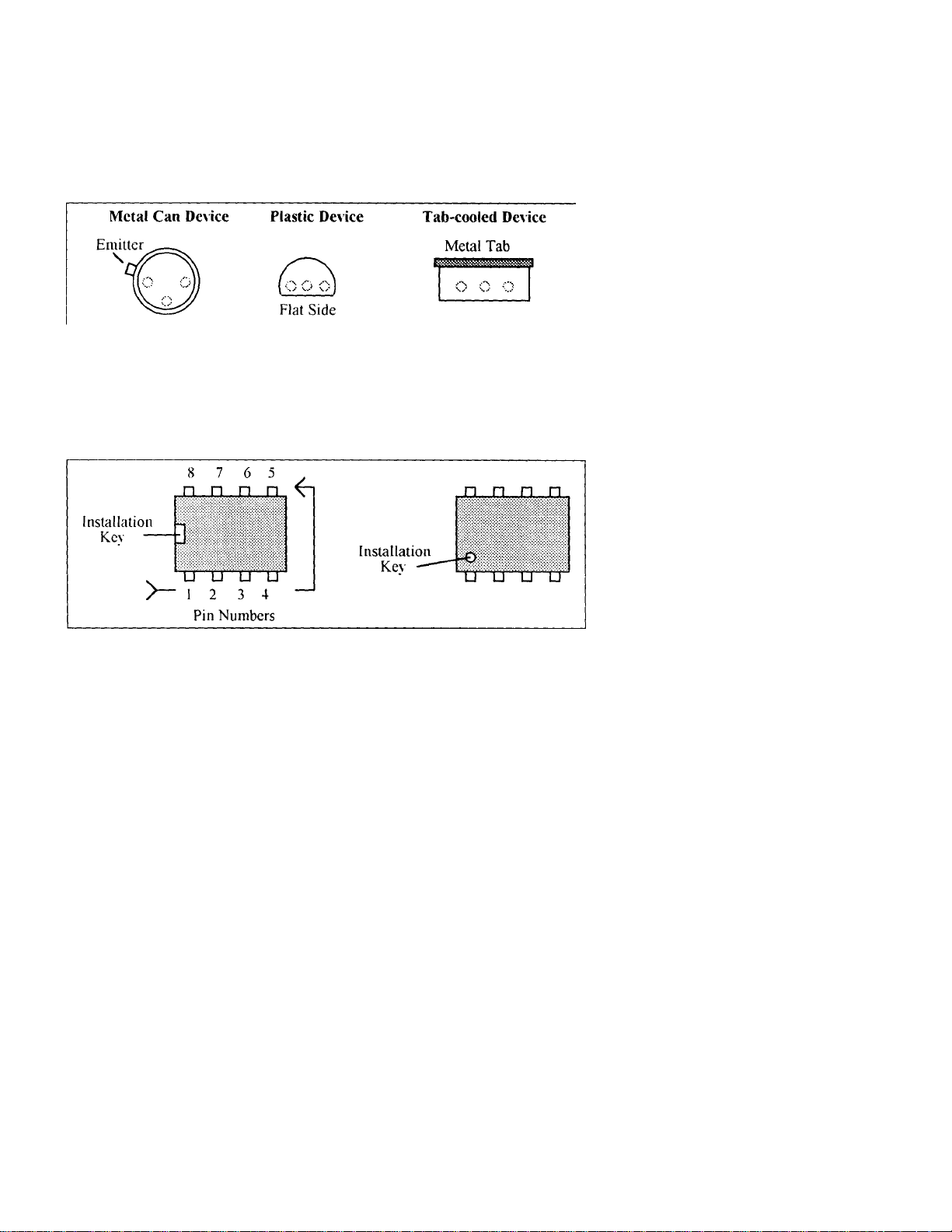
Integrated Circuits: Proper IC positioning is indicated by a dot or square
marking located on one end of the device. A corresponding mark will be silkscreened on the PC board and printed on the kit's parts-plac ement diagram. To
identify specific IC pin numbers for testing purposes, see the diagram below.
Pin numbers always start at the keyed end of the case and progress counterclockwise around the device, as shown:
Page 7

VEC-820K Instruction I Manual CW Filter Kit
p
Your kit should contain all of the parts listed below. Please go through the parts
bag to identif
building, If any parts are missing or damaged, refer to the warranty section of
this manual for replacement instructions. If you can't positively identify
unfamiliar item in the bag on the basis of the info rmation give n, set i t aside until
all other items are checked off. You may then be able to identify it by process of
elimination, Finally, your kit will go together more smoothly if parts are
organized by type and arranged by value ahead of time, Use this inventory as an
opportunity to sort and arrange parts so you can identify and find them quickly.
Qty Part Description Designation
©
6 24.3K* ohm resistor (red-yellow-orange-brown) R9,R10,R12 1,R12.
-4 681 K* resistor (blue-gray-brown-orange) R5, R6. R7, R8
4 1.82M* ohm resistor (brown-gray-red-yellow) RI, R2. R3, R-4
8 1000 pF poly capacitor (1000J) C1,C2,C3,C4,C5,C6
1 01 uF disc ce ram ic capacitor (103Z) C9
2 10 uF electrolytic capacitor (10uf) CIO, c1 I
2 1-4 p in IC sock ets For U1 . U2
2 LM747 Op Amp IC U l . U2
I 4P4T Slide Switch with screws SW l
6 6" Insulated wires Circuit wiring
I 9-volt batter, snap
1
1
y
and inventory each item on the checklist before you start
R13,R14
C7,C8
GND. VCC
PC board VEC-820K
Owner's Manual
,
an
" These parts have a 1% tolerance, The tourth co lor ba nd on these
onents will BROWN, specifying a l% tolerance.
com
Page 8

Page 9

'
y
y (
g
,
,
,
-
'
STEP-BY-STEP ASSEMBLY
Before assembling your kit, please take time to read and understand the VEC kit
warranty pr i nted on the insi de cover of t his manual. Also, read through the
assembly instructions to make sure the kit does not exceed your skill level.
you begin construction, your kit will be non-returnable.
Finally, if you haven't
already done so, please verify that all parts listed in the inventory are included.
If anything is missing or broken, refer to the warranty instructions for
replacing missing or damaged parts.
Note that part designators. such as R1, C3, etc., appear on a silk-screened legend
on the component-mounting side of the printed circuit board. This corresponds
with the parts placement page in the manual. All parts will be inserted on the
silk-screen side of the board.
If you have last-minute questions about what you need to build your kit, please
refer back to the section titled "Tools and Supplies". If you're ready to begin
now. here we go! The directions use two sets of check boxes. Check one when a
step is complete and use the other for double-checking your work before
operation.
Once
Important Note:
Capacitors Cl-C8 are made of a polystyrene type material. Avoid
overheating these components when soldering to prevent melting the capacitor
bod
.
1. Locate capacitor C 1 (1000pF). This is a polystyrene capacitor and
will be marked with a "1000P on the bod
actual value in pF).
2. Mount C l and solder both leads in place, making sure the capacitor
remains seated, Remove excess leads on the bottom side of the board
with dia
onal cutters.
3. Locate capacitor C2 (1000 pF). This is another polystyrene capacitor.
and it will be marked with a "1000J" (actual value in pF). Carefully
install C2 in the same manner as C1
and solder in place.
4. Locate capacitor C3 (1000pF). This is another polystyrene capacitor and
it will also be marked "1000T' (actual value in pF). Carefully install C3
in the same manner as C2, and solder in place.
5. Locate capacitor C4 (1000pF). This is another polystyrene capacitor and
will be marked "1000J" (actual value in pF). Carefully install C4 in the
same manner as C3
and solder in place.
6. Locate capacitor C5 (1000pF). This is yet another polystyrene capacitor
and will be marked "1000J" (actual value in pF). Carefully install C5
in the same manner as C4
and solder in place.
Page 10

1'EC-820K Instruction afanual CIf Filter
,
,
p
)
g
7. Locate capacitor C6 (1000pF). This is yet another polystyrene capacitor
and will be marked "1000J" (actual value in pF). Carefully install C6 in the
same manner as C5
and solder in place.
8. Locate capacitor C7 (1000pF). This is yet another polystyrene
capacitor and will be marked "1000J" (actual value in pF). Carefully install
C7 in the same manner as C6
and solder in place.
9. Locate capacitor C8 (1000pF). This is the final polystyrene capacitor
and will be marked "1000J" (actual value in pF). Carefully install C8 in the
same manner as C7, and solder in place.
10. Locate capacitor C9 (.0luF). This is a disc ceramic type capacitor and
will be marked "103" or "103Z" (actual value in uF). Carefully install C9.
ensuring not to chip the ceramic material. Once installed, then solder in
lace.
-
11. Locate resistor R1. This is a 1.82M resistor (brown-gray-red-N
brown
.
ellow
Carefully bend the leads close to the resistor body to form right-angles (see
followin
diagram).
12. Insert RI into its mounting holes so the resistor body rests against the
board. Solder in place and trim the leads.
13. Locate resistor R2. This is a 1.82M resistor (brown-gray-red yellowbrown). Carefully bend the leads close to the resistor body as in Step
14. Insert R2 into its mounting holes so the resistor body rests against
the board. Solder in place and trim the leads.
15. Locate resistor R3. This is a 1.82M resistor (brown-gray-redyellow brown). Carefully bend the leads close to the resistor body as in
16. Insert R3 into its mounting holes so the resistor body rests against
the board. Solder in place and trim the leads.
Page 11

'-
17. Loca,td r"c'sistor R4. This is a 1.82M resistor (brown-gray-red-Nellmc
brotk W). "~'arefiilly bend the leads close
#11.
20. Insert R> into its mounting holes so the resistor body rests against the
21 Locate resistor R6. This is a 681K resistor, (blue-gray-brown-orange
brown). Carefully bend the leads close to the resistor
body.as in Step #1l.
22. Insert R6 into its mounting holes so the resistor body rests-against the
board. Solder in place and trim the leads.
broN%n). Carefully bend the leads close to the resistor body as in Step
24 Insert R7 into i ts mou nting hol es so th e resisto r body r ests aga inst the
the resistor body as in Step
to
"
-
'
-
-
25. Locate resistor R8. This is a 681K resistor (blue-gray-brown-orangebroL%n). Carefully bend the leads close to the resistor body as in Step #1 l.
26. Insert R8 into its mounting holes
board. Solder in place and trim the leads.
27. Locate resistor R9. This is a 24.3K resistor (red-yellow-orange-redbrown). Carefully bend the leads close to the resistot body as in Step #11.
28. Insert R9 into its mounting holes so the resistor body rests against the
29. Locate resistor R10. This is a 24.3K resistor (red-yellow-orange-redbrown). Carefully bend the leads close to the resistor body as in Step #11.
the resistonbody rests against the
so
Page 12

F EC-820K Instruction Afanua
/
p
p
p
p
p
p
g
CII'Fi/ter
30. Insert RIO into its mounting holes so the re sistor bod y rests a gainst the
board. Solder in
lace and trim the leads.
31. Locate resistor R11. This is 24.3K resistor (red-yellow-orange-redbrown). Carefully bend the lea d s close to the resistor bod y as in Step #I1.
32. Insert RI 1 into its mounting holes so the resistor body rests aga inst the
board. Solder in
lace and trim the leads.
33. Locate resistor R12. This is 24.3K resistor (red -yellow-orange-redbro,yn). Carefully bend the lea ds close to the resistor body as in Step
#11.
34. Insert R12 into its mounting holes so the resistor bod_ N re sts agai nst
the board. Solder in
lace and trim the leads.
35. Locate resistor R13. This is 24.3K resistor (red-yellow-orange-red-
brown). Carefully bend the lea ds close to the resistor bod y as in Ste p #11 .
36. Insert R13 into its mounting holes so the resistor body rests aga inst the
board. Solder in
lace and trim the leads.
37. Locate resistor R14 This is 24.3K resistor (red-yellow-orange-red-
brown). Carefully bend the lea ds close to the resistor bod y as in Ste p #11 .
38. Insert R14 into its mounting holes so the resistor body rests aga inst the
board. Solder in place and trim the leads. Save the excess trimmed pieces of
resistor lead. You will need it later.
39. Locate a G" length piece of insulated wire. and cut piece 1 1/4" long off
40. Using the wire strippers, re move 1/4" of insulation fr om eac h end of the
1 1/4" wire.
41. Insert the bare ends of the 1 1/4" wire into the holes on the circuit
board located at JMP2. Please refer to the section titled "Parts Placement".
Fi
ure 1 for the location of JNIP2.
42. Solder the 1 1/4" wire in place at JNIP2 and trim the excess wire.
43. Locate the
ieces of excess resistor lead you saved back in step #38.
44. Install the excess lead in the holes located at JNIP I on the circuit
board. Solder in
lace and trim the excess lead.
Page 13

-
(
45. Locate capacitor CIO (IOuF). This is an electrolytic type capacitor
and will be marked "lOuF" (actual value in uF). Carefully install C9:
be sure to orient the negative end of the capacitor properly. Please
refer to the section titled, "Parts Placement", Figure I for correct
orientation of CIO. Once installed, then solder in place and trim
excess lead.
46. Take the remaing 6" lengths of insulated wire and cut them in half.
"
47. Using the i yire strippers. r emove a 1/-1 " piece of insul ation fro m
48. Take a 3" piece o f insulated wire and insert o ne end into the hole
silk-screened INP UT on the cir cuit board. S older in pl ace and trim the
49. Take one 3" piece of insulated wire and insert one end into the hole
silk-screened #1 on the circu it board. So lder in place and trim the ex cess
50. Take one 3" piece of insulated wire and insert one end into the hole
silk-screened #2 on the circu it board. So lder in place and trim the
51. Take one 3" piece of insulated wire and insert one end into the hole
silk-screened #3 on the circu it board. So lder in place and trim the ex cess
lead.
'
52. Locate the batt ery snap. In sert the RED le ad into the h ole silk-
screened VCC on th e circuit board. Solder in p lace and trim the ex cess
53. Insert the BLACK lead of the battery into the hole silk-screened GND
on the circuit board. Solder in place and trim the ex cess lead.
54. Locate the 4P -1T slide switch
55. Inspect the slide switch for tarnished contacts. Remove any tarnish
with very fine sandpaper so the contacts are nice and shiny. This will
Note: Please refer to the section titled, "Parts Placement" Figure 2 for Steps 56
through 66.
56. Connect one 3 " piece of insul ated wire to P oint A on S W1. Do
S W
Page 14

F EC-820K I
nstruction .t fanual Cff Filte
it
p
p
p
g
57. Connect the o ther end of the i nsulated wir e located at t he INPUT
location on the circuit board to
the excess lead fro m the switch co ntact.
58. Locate capacito r C 11 (1 Ouf . This is an electrolyti c type capa citor
and will be marked "IOuF" with an arrow pointing to the negative
59. Trim the positive lead of C 11 so about only 3/8" of the lead
Point A
on SW 1. Solder i n place and tri m
r K
60. Connect the positive lead of C 11 at
this switch contact yet.
61. Connect the other end of the insulated %sire located at #3 on the
circuit board at
from the switch contact.
62. Connect the other end of the insulated wire located at #2 on the
circuit board at
from the switch contact.
63. Connect the other end of the insulated wire located at #1 on the
circuit board at
lead from the sN vtich con tact.
64. Cut a 1 1/4"
65. Using the wire strippers. remove a 1/4" piece of the insulation from
each end of the 1 1 /4" wire.
66. Connect the t t/4" piece of wire between
Solder in
67. Locate (1) 14
68. Install the IC sock et at the UI lo cation on th e circuit board. Be
careful to orien t the socket correctly ac cording to t he "Parts P lacement"
section Fi
Point
Con SW l. Solder in place and t rim the excess l ead
Point D
ure 1.
on SW 1. Solder i n place and trim the excess l ead
Point F
iece of wire from on e of the remain ing 3"
lace and trim the exc ess lead fro m the switch co ntact.
in IC socket.
on SW I. Solder in p lace and tri m the excess
Point B
on SW 1. Do not solder
Points B and E
on SW l.
69. Carefully bend over the four corner pins of the socket against the
70. Locate the re maining 14 pin IC socket.
71. Install the IC socket at the U2 location on the circuit board. Be
careful to orien t the socket correctly ac cording to t he "Parts P lacement"
section Figure 1.
Page 15

sockets for U 1 and U2. Please refer to the "Parts Placement" section.
p
Figure 1 for proper orientation. Be sure not to bend any of the pins
underneath the IC body, and that all pins are inserted into the socket.
At this point, your kit is finished and it's time to take a well-earned break!
When you come back. be sure to give your work a close "quality control"
inspection.
PC Board Ins
Before applying power to your kit, give it a thorough QC (quality control)
inspection. This xyill help you find inadvertent assembly errors that might
prevent the filter from working or cause damage to sensitive parts. Follow this
procedure:
Compare parts locations against the parts-placement diagram. Was each
part installed where it is supposed to be? Was the correct value used? Start
at one side of the board and work your way across in an organized
pattern.
I] Inspect the solder side of the board for cold-solder joints and solder
bridges betNycen tracks or pads. Use a magnifying glass to obtain a clear
view of the track area. If you suspect a solder bridge, hold the
board in front of a bright light for a better view. All joints should be
smooth and shiny. indicating good solder wetting and flow. Resolder any
beaded or dullappearing c onnections.
If you find a construction error and need to remove a part or two, it will be
easier if you have the right tools. One very convenient item for freeing
soldered-in parts is a "solder sucker". This consists of a suction bulb or a
spring loaded vacuum pump that draws molten solder away from the pad and
lead. Alternatively. you may use a special copper braid ca lled "solder wick"
(solder suckers and solder wick are both available a t your local Radio Shack or
electronics supply house). If you suspect you've damaged a compone nt during
removal, better to replace it than risk reusing it!
ection:
Finally, rosin flux can absorb moisture, which may cause a problem for some
electronic equipment. To remove flux, use isopropyl alcohol (or 95% grain
alcohol) and an old toothbrush. Apply a generous amount of alcohol with the
toothbrush and scrub gently. Once the flux has fully dissolved, blot the bottom
of the board dry with an untreated tissue. Giv e it a final alcohol wash, and
allow to dry thoroughly.
Page 16

CAUTION: ALCOHOL IS HIGHLY FLAMMABLE AND MUST BE USED WITH
g
ADEQUATE VENTILATION! USE SAFETY GOGGLES, AND
AVOID PROLONGED SKIN CONTACT. IT
THIS OUTDOORS.
'
S ALSO BEST TO DO
Now that assembly and inspection is completed, you're ready to begin the testing
and ali
nment phase of construction.
The best way to test the VEC-820K is with a calibrated audio signal generator and
oscilloscope. However. VEC-820K does not require any alignment. If all
components are installed cor rec tly and in the prope r pla ces, the cente r freq uenc y
of the filter will be between 750-800 hertz. The filter has three switch selectable
selectivity cutoff points, 80, 110. and 180 hertz_. The switch positions on
SWl from left to right are BYPASS. 180. 110, and 80. The 80 hertz cutoff is the
fourth switch position from the left and is the narrowest filter cutoff. while the
180 hertz cutoff is the second position from the left and is the N%idest filter
cutoff.
Probably the best method of seeing if the VEC-820K is working, or not, is to
listen to some "on the air" CW signals. Then using SW1, select the filter cutoff
position that best cleans up the signa l being rece ived .
If you are trying to pick one signal out of a very tight band pile up, the n try using
the 80 hertz cutoff. The 80 hertz cutoff provides the highest selectivity and will
greatly help you in "pulling out" those hard to get signals.
If the CW signal you are receiving is noisy with some static , then tr v either the
110 or 180 filter cutoffs. However, in these positions the filter will let slightly
more noise through. but in some ca ses this may be de sira ble. The be st way to se e
which position works the best is to try it. This way you can re ally he ar wha t the
filter is doing for the received signal, and which switch position works the best in
different band conditions.
Page 17

You may use the VEC-820K with any communications receiver or scanner with
p
p
p
a BFO (Beat Frequency Oscillator). You can also use the VEC-820K with a
ham-radio transceiver in either LSB or CW mode. The VEC-820K requires a 9volt battery power source.
There are a few items that you will need to operate the VEC-820K. We have
rovided a list of these items below for your convience.
Communications Receiver, scanner. or Ham Radio transceiver Nyith
0 9-Volt transistor radio batten
External s
Receiver or Scanner
eaker with cli
As mentioned above . you can use the VEC-820K with a communications
receiver or scanner. The receiver or scanner must be equipped with a BFO, or
Beat Frequency Oscillator. The BFO will allow you to fine tune the received
CW signal to the VEC-820 center frequency. The center frequency of the filter
being 750-800 hertz.
The filter requires audio from the external speaker or headphones output of the
receiver or scanner. This positive side of the audio signal is applied to the
insulated Nyire connected to
Point
A on SW 1. Apply the negative side of the
audio to the negative side of the battery snap. Please refer to the "Parts
Placement" section, Figure 2 for the location of
Point A
on SW 1.
Nest, connect the POSITIVE lead of the external speaker to the NEGATIVE end
of C11. Please refer to the "Parts Placement" section Figure 3 for the location of
C 11. Connect the NEGATIVE lead of the external speaker to the point labeled
GND on the circuit board. Again please refer to the "Parts Placement" section
Figure 1 for the location of the point labeled GND on the circuit board.
Nest, turn the receiver volume all the way down, then clip the 9-volt battery to
battery snap. Set SW1 to the far left position. Now turn the receiver up slightly
so you can hear the received signals on the external speaker. The signal you are
listening to is the "raw" or "unfiltered" signal. Using the tuning knob on the
radio find a CW signal. A good place to find CW signals is in the Amateur
Radio bands. Once you find a CW signal switch SW I to the 110 filter cutoff.
The 110 position is the third from the left. When you switch to the 110 cutoff,
you will notice that the signal sounds cleaner than before. You can now fine
tune the radio tuning knob for the best received signal. If using a
Page 18

I E('-830/: Instruction _Manual Cll' Filter
p
p
p
p
communications receiver or scanner with a BFO control. use this control to
fine tune the recei ved CW signal. If the recei ver or scann er you are usin g does
not have a BFO control, it will be very difficult trying to tune the signal in
properly.
If the signal you are trying to receive is i n a "pile u p", then tr y the 80 hertz
filter cutoff. Then fine tune the receiver to "
Operation with an Amateur Radio tr ansceive r is basicall y the same, b ut you
would use either LSB (Lower Side Band) or CW mode. All other connections
arc the same.
ull out" the desired signal.
IN CASE OF DIFFICULTY
No Signal Filtering:
A neNyly constricted filter that fails to work upon initial power up. generally requires
a ver< close and care ful inspecti on of all wor k. Please go back through all steps of
assembly and insp ection. re ferring to the "P arts Place ment" Figure s
1. 2. and 3. Most of the time there will be a part that is not installed or not installed
properly. a wrong valu e part in p lace of another. o r a broken part. A close
inspection at this point will reveal some accidental mistake.
Intermittent Filter O
A filter that operates intermittently may have poor solder connections. a
problem Nyith broken wires, or low voltage power source. Self-oscillation.
may be caused b_v a defective U1 or U2. Also check for dirty or intermittent
switch operation.
Filter Sto
A working filter that fails "in-service" generally indicates a failure of in one or
both U l or U2. If you suspect a bad U 1 or U2. then
with your fingers. If the part is bad, it could be HOT and could cause a serious
burn. Other things that should be checked is the supply voltage of the 9-volt
No Speaker Audio:
No speaker audio can be a symptom of a bad SW 1, a broken Nvire or a bad C
11. Check the voltage from the 9-volt battery. A broken Nvire at the audio
in
If technical assistance or factory repair is desired, please refer to the warranty
s Filtering:
'
ut to the filter can also attribute to no speaker audio.
eration
do not touch
the part
Page 19

.
50-800
p
,
.
'-
"
THEORY OF OPERATION AND SPECIFICATIONS
Circuit Description:
The VEC-820K uses two UA747 operational amplifier integrated circuits to
form four low Q cascaded stages NNith no insertion loss. This results in a ven
narrow band« idth and extremely high skirt rejection with minimum audible
ringing. making good signal copying possible. The center frequency is
betNNeen 7
ecifications:
S
hertz. The filter is abl e to drive an 8 ohm speaker or
Bandwidth:.. .................................80 Hz
Skirt Re_jcolon:..................... ......... At least 60dB do%Nn 1 octave from
110 Hz, 180 Hz (sNNitch
ENCLOSURE
Vectronics has designed a matching enclosure just for your
CIF Audio Filler Kit.
includes knobs. hard\\are. decals. and rubber feet. The
The matching encl osure is an all
-
VEC-820K
metal box which
Vectronics model
Super
Page 20

 Loading...