

Page 1
SOC-H1T1
Item name
Item code
Description/option
SOC-H1T1-A3-1
40-30 0156
Signal converter for humidity & temperature sensor, incl. sensor element
AES1-HT-A3 and cable gland PG9 (AMC-1)
SOC-H1T1-A3-1-W0
40-30 0xxx-0
0
Temperature range: -40…60 °C (-40…140 °F) (Default)
SOC-H1T1-A3-1-W1
40-30 0xxx-1
1
Temperature range: -35...35 °C (-31…95 °F)
SOC-H1T1-A3-1-W2
40-30 0xxx-2
2
Temperature range: 0…50 °C (32…122 °F)
SOC-H1T1-A3-1-W3
40-30 0xxx-3
3
Temperature range: Special – Specify in order
Item name
Item code
Humidity
accuracy
[%rH]
Temperature
accuracy [K]
@25°C (77°F)
Description/option
AES1-HT-A2
40-50 0067
± 2%
± 0.3°
Humidity - temperature sensor element
AES1-HT-A3
40-50 0068
± 3%
± 0.4°
AES1-HT-A5
40-50 0069
± 5%
± 0.5°
Item Name
Item Code
Description/Option
OPC-S
40-50 0029
Built in display & programming module
OPU-S
40-50 0006
External display module
AMS-1
20-10 0116
Weather shield to protect the sensor element
AMC-2
40-50 0074
Conduit connector NPT 1/2
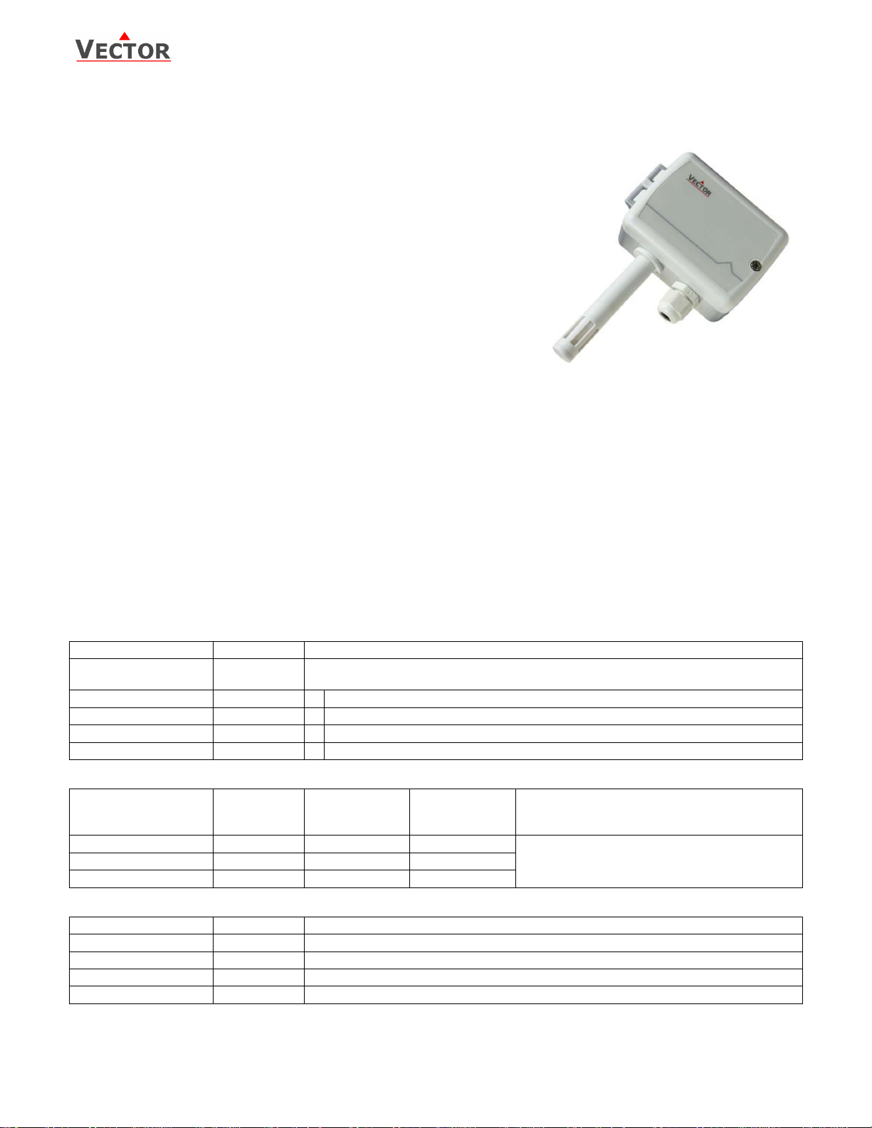
SOC-H1T1 Outdoor Humidity and Temperature Transmitter
Features
Replaceable sensor element
Outdoor humidity and temperature measurement
Minimum and maximum value memory
0…10V, 0…20mA or 2…10V, 4…20mA output selectable with jumpers
Optional alternative signal ranges programmable
Selectable averaging signal
Optional LCD display (OPC-S) or external display (OPU-S)
Status LED
Applications
Outdoor humidity and temperature measurement for HVAC applications
Recording of minimum and maximum values for critical environments
Supervision of critical humidity and temperatures
Humidity and temperature transmitter
A unique capacitive sensor element is used for measuring relative humidity while temperature is measured by a band-gap
sensor. The applied measuring technology guarantees excellent reliability and long term stability. The microprocessor samples
the humidity and temperature once per second. It calculates an averaging signal over a preset number of seconds and
generates the output signal based on lower and upper signal range values. Standard range is 0…100% RH, -40…60 °C
(-40…140 °F) and 10 seconds average. The signal range of the temperature measurement and the averaging samples may be
customized. Standard output signal range and types may be selected by jumpers. Standard signal ranges are: 0…10 VDC,
0…10 VDC, 4…20 mA and 0…20 mA. Other ranges can be defined by using a programming tool (OPU-S or OPC-S). A version
with display is possible by ordering the integrated display accessory OPC-S.
Minimum and maximum values
Using the programming tool, the user has the option to read out and reset minimum and maximum values. The minimum and
maximum values may as well be used as output signals. The minimum and maximum values are saved into the EEPROM and
are available after a power interruption.
Ordering
Per default a sensor element with 3% RH accuracy and a PG9 cable gland for cables 4 – 8 mm (AWG 6 – 1) is included.
Contact your local sales contact to order sensing elements with different accuracies or if you prefer a sensor with conduit
connectors or a built in display module.
Signal converter
Sensor element
Accessories
Doc: 70-07-0166, V1.1, 20170131, Subject to alteration, ©Vector Controls GmbH, Switzerland, www.vectorcontrols.com Page 1
Page 2
SOC-H1T1
Power Supply
Operating Voltage
Transformer
24 V AC 50/60 Hz 10%, 24VDC 10%
SELV to HD 384, Class II, 48 VA max.
Power Consumption
Max. 2 VA
Terminal Connectors
For wire 0.34…2.5 mm2 (AWG 24…12)
Sensing Probe
Humidity Sensor:
Range
Measuring Accuracy
Hysteresis
Repeatability
Stability
Capacity sensor element
0…100 % rH
See Figure 1
1%
0.1%
< 0.5% / year
Temperature Sensor:
Range
Measuring Accuracy
Repeatability
Bandgap sensor
-40…70 °C (-40…158 °F)
See figure 2
0.1 °C, 0.2 °F
Signal Outputs
Analog Outputs
Output Signal
Resolution
Maximum Load
DC 0-10 V or 0…20 mA
10 Bit, 9.7 mV, 0.019.5 mA
Voltage: ≥1kΩ Current: ≤250Ω
Environment
Operation
Climatic Conditions
Temperature
Humidity
To IEC 721-3-3
class 3 K5
-40…70 °C (-40…158 °F)
<95% R.H. non-condensing
Transport & Storage
Climatic Conditions
Temperature
Humidity
Mechanical Conditions
To IEC 721-3-2 and IEC 721-3-1
class 3 K3 and class 1 K3
-40…80 °C (-40…176 °F)
<95% R.H. non-condensing
class 2M2
Standards
conformity
EMC Directive
Low Voltage Directive
2004/108/EC
2006/95/EC
Product standards Automatic electrical controls for
household and similar use
EN 60 730 –1
Electromagnetic compatibility for
domestic and industrial sector
Emissions: EN 60 730-1
Immunity: EN 60 730-1
Degree of Protection to EN 60529
IP63 if correctly mounted with AMS-1
Safety Class
III (IEC 60536)
General
Housing materials Cover, back part
Filter material
PC+ABS (UL94 class V-0)
PTFE coated 1μm pores
Dimensions (H x W x D):
150 x 91 x 47mm (5.9” x 3.7” x 1.9”)
Weight (including package)
220g (7.8 oz)
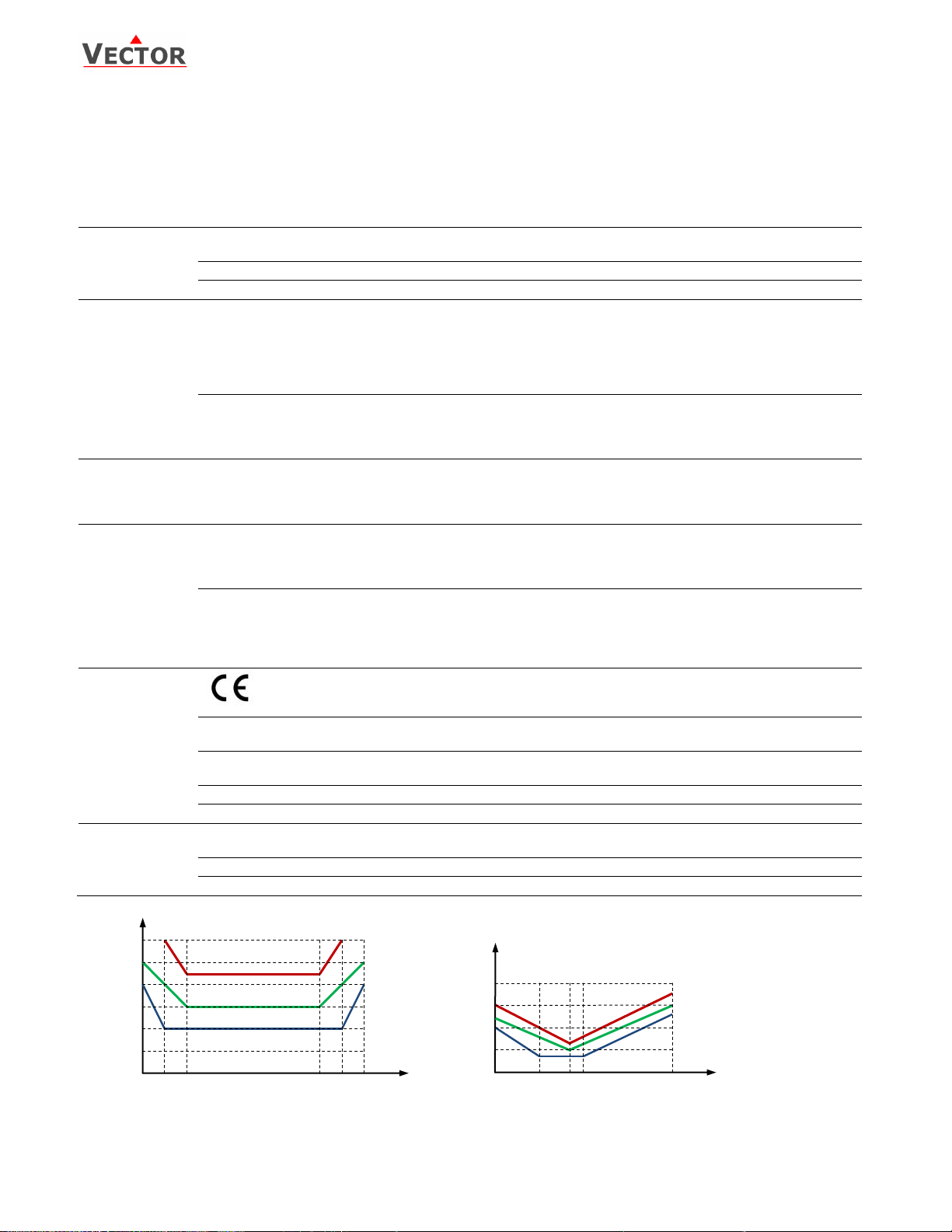
Figure 1: Max RH-tolerance at 25°C (77°F)
per sensor type
Relative humidity absolute accuracy
%R
%RH
10
20
30
40
100
90 0 50
60
70
80
±1
±0
±2
±3
±4
±5
AES-HT-A2
AES-HT-A3
AES-HT-A5
Temperature accuracy
±0.5
±0
±1.0
±1.5
±2.0
AES-HT-A2
AES-HT-A3
AES-HT-A5
°C
-20 0 20
40
-40
60
80
100
120
°K
-4
32
68
104
-40
140
176
212
248
°F
Figure 2: Max T-tolerance by sensor type
Technical Specification
Warning! Safety advice! This device is intended to be used for comfort applications. Where a device failure endangers
human life and/or property, it is the responsibility of the owner, designer and installer to add additional safety devices to
prevent or detect a system failure caused by such a device failure. The manufacturer of this device cannot be held liable for
any damage caused by such a failure. Failure to follow specifications and local regulations may endanger life, cause
equipment damage and void warranty.
Doc: 70-07-0166, V1.1, 20170131, Subject to alteration, ©Vector Controls GmbH, Switzerland, www.vectorcontrols.com Page 2
Page 3
SOC-H1T1
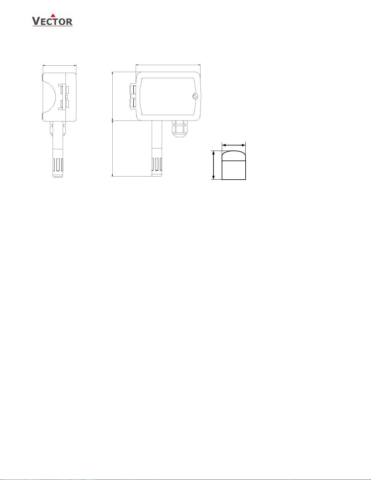
82 (3.2)
47 (1.9)
91 (3.6)
68(2.7)
AMS-1
34(1.3)
42(1.7)
Dimensions mm(inch)
Mechanical Design and Installation
The unit consists of two parts: (a) The back part with the probe and (b) the cover.
Mounting location
The transmitter should be installed, probe facing down, directly on the wall, in a weather protected area. The weather shield
accessory is recommended, in case the transmitter is exposed to weather and direct sunlight.
Warning about storage, packaging and usage environment
The sensing part is a polymer, which measures the humidity in the ambient air. For proper sensor operation some mandatory
precautions need to be taken during storage, packaging and usage.
The transmitter and its sensing element should not be packaged, stored or used in out-gassing plastic materials, which could
cause sensor contamination. In particular, it is recommended not to use any glue or adhesive tapes (Sellotape, Scotch-Tape,
Tesa-Film, etc.)within the package or close proximity of the sensor. Foamed materials often cause contamination problems
and should not be used to package the transmitter. Best packaging material is a simple cardboard box or a deep-drawn
plastic case in a cardboard box.
Mounting instruction / replacing the sensor element
See installation sheet no. 70-000530 (www.vectorcontrols.com)
Doc: 70-07-0166, V1.1, 20170131, Subject to alteration, ©Vector Controls GmbH, Switzerland, www.vectorcontrols.com Page 3
Page 4

SOC-H1T1
Parameter
Description
Range
Default
IP 00
TI1: Celsius or Fahrenheit, C = OFF, F = ON
ON, OFF
OFF
IP 01
TI1: Samples taken for averaging control signal
1…255
10
IP 02
TI1: Calibration
-10…10
0
IP 03
TI1: Minimum temperature
-40…215 °C/F
0 °C
IP 04
TI1: Maximum temperature
-40…215 °C/F
50 °C
IP 05
H1: Show Percent
ON, OFF
ON
IP 06
H1: Samples taken for averaging control signal
1…255
10
IP 07
H1: Calibration
-10…10%
0
Parameter
Description
Range
Default
OP 00
AO1: Humidity: Configuration of output signal:
0 = Feedback humidity input,
1 = Feedback humidity minimum value
2 = Feedback humidity maximum value
0 – 2
0
OP 01
AO1: Humidity: Minimum limitation of output signal
0 – Max %
0%
OP 02
AO1: Humidity: Maximum limitation of output signal
Min – 100%
100%
OP 03
AO2: Temperature: Configuration of output signal:
0 = Feedback temperature input,
1 = Feedback temperature minimum value
2 = Feedback temperature maximum value
0 – 2
0
OP 04
AO2: Temperature: Minimum limitation of output signal
0 – Max %
0%
OP 05
AO2: Temperature: Maximum limitation of output signal
Min – 100%
100%
Signal Type
JP1, JP2
0 – 10 V
(1-2)
0 – 20 mA
(2-3)
Signal Range
JP3
0 – 10 V, 0 – 20 mA
(1-2)
2 – 10 V, 4 – 20 mA
(2-3)
Configuration
The transmitter can be adapted to fit perfectly into any application by adjusting the software parameters. The parameters are
set with the operation terminals OPU-S or OPC-S. The OPU-S may also be used as remote indicator.
Input configuration
Output configuration
Output signal configuration
The analog output signal type may be configured with a jumper for 0-10 VDC or 020 mA control signals. The jumpers are located next to the terminal connector of
each analog output. See table below for jumper placement. The factory setting is
to 0-10 VDC.
The signal range may be set with JP3 for both analog outputs. JP3 will only operate
if the output range specified with OP01 and OP02 or OP04 and OP05 is left at the
default position of 0…100%. With any other setting the position of JP3 has no
influence and the range defined with the output parameters applies.
Doc: 70-07-0166, V1.1, 20170131, Subject to alteration, ©Vector Controls GmbH, Switzerland, www.vectorcontrols.com Page 4
Page 5

SOC-H1T1
OPU-S
JP1
JP2
JP3
JP3 Signal range
U1, U2: 0-10V
I1, I2: 0-20mA
U1, U2: 2-10V
I1, I2: 4-20mA
3
2
1
3
2
1
JP1, JP2 Signal type
U1 / U2
0-10V, 2-10V
I1 / I2
0-20mA, 4-20mA
3
2
1
3
2
1
STATUS
LED
Status LED
LED indicates status
No light: either no power or sensing element is
reversed.
5 sec blinking: Normal
2 sec blinking: OPA or OPC connected
1 sec blinking: Sensor element error
1 2 3
4
G 24V
G0 0V
U1/ I1 AO H
U2/ I2 AO T
Jumper Settings
Doc: 70-07-0166, V1.1, 20170131, Subject to alteration, ©Vector Controls GmbH, Switzerland, www.vectorcontrols.com Page 5
 Loading...