

Page 1
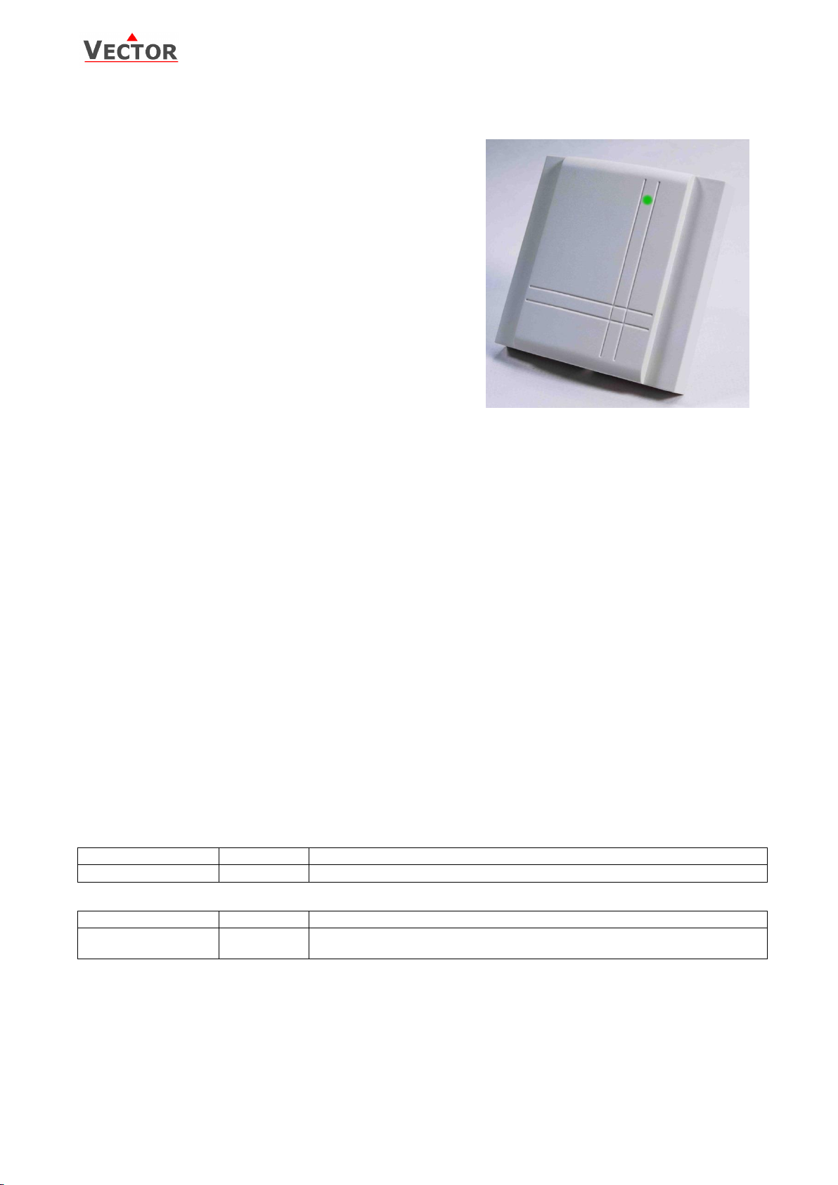
SRC-C1
Item name
Item code
Description/option
SRC-C1
40-30 0062
CO2 transmitter
Item name
Item code
Description/option
OPA-S
40-50 0006
External display module.
For the correct display of values V1.4 and later is required
SRC-C1 Indoor CO2 Transmitter
Features
Indoor CO2 measurement
Indication with three color led
Minimum and maximum value memory
0…10 V, 0…20 mA or 2…10 V, 4…20 mA measuring signals
selectable with jumpers
Optional alternative signal ranges programmable
May be used as simple P-controller
Selectable averaging signal
Optional external display (OPA-S)
Status LED
Applications
Indoor CO2 measurement
Recording of minimum and maximum limits for critical
environments
Direct control of extraction fan
CO2 transmitter
The CO2 concentration is measured through non-dispersive infrared (NDIR) waveguide technology with ABC automatic
background calibration algorithm. The applied measuring technology guarantees excellent reliability and long term
stability. The microprocessor samples the CO2 once per second. It calculates an averaging signal over a preset number
of seconds and generates the output signal.
The output signal range and type may be customized by jumpers and if required by a programming tool. Standard
signal ranges are 0-10 VDC, 2-10 VDC, 4-20 mA and 0-20 mA. These ranges can be set by jumpers. Other ranges can
be set by using the external display and programming module. (OPA-S)
Automatic Baseline Calibration ABC
The ABC background calibration constantly supervises the measured CO2 concentrations. The calibration function
expects the CO2 values sink to 400 ppm when the room is not occupied. Over a period of several days the controller
tries to reach this value step by step through recalibration of 30ppm per day max. In order to reach the given
accuracy, it is required that the sensor is for at least 3 weeks in operation.
Note: The ABC calibration works only in those applications where the CO2 concentration sinks regularly to fresh air
levels of 400 ppm. For special applications such as green houses, animal farms, etc. the ABC calibration should be deactivated and the sensor should be manually calibrated. The automatic calibration can deactivated through the
external operation terminal. The Sensor can be calibrated by the client and does not need to be sent in for calibration.
See last page for details.
Minimum and maximum values
Using a display & programming accessory, the user has the option to read out and reset minimum and maximum
values. The minimum and maximum values may as well be used as output signals. The minimum and maximum
values are saved into the EEPROM and are available after a power interruption.
Indication of air quality indication:
A three color LED is used to indicate air quality: Green light for low CO2 concentration, orange light for medium and
red light for high concentration. The levels for low-medium-high may be programmed.
Default settings are 0 ppm< low < 800 ppm< medium < 1500 ppm < high.
Ordering
Accessories
Doc: 70-00-0220, V1.2, 20170131 © Vector Controls GmbH, Switzerland Page 1
Subject to alteration www.vectorcontrols.com
Page 2
SRC-C1
Power supply
Operating voltage
24 V AC 50/60 Hz ± 10%, 24 VDC ± 10%
SELV to HD 384, class II transformer, 48 VA max.
Power consumption
Max. 2 VA
Connection
Terminal connectors
For wire 0.34…2.5 mm2 (AWG 24…12)
CO2 measurement
Sensing method
Non-dispersive infrared (NDIR) waveguide
technology with ABC automatic
background calibration algorithm
Sampling method
Diffusion
Response time (T
1/e
)
40 sec diffusion time
Measurement range
0 - 5000 ppm
vol.
Repeatability
± 20 ppm ± 1 % of measured value
Accuracy
± 30 ppm ± 3 % of measured value
Pressure dependence
+ 1.6 % reading per kPa deviation from normal
pressure, 100 kPa
Signal outputs
Analog outputs
Output signal
Resolution
Maximum load
DC 0-10 V or 0…20 mA
10 bit, 9.7 mV, 0.019.5 mA
Voltage signal: ≥1kΩ, current signal: ≤500Ω
Environment
Operation
Climatic conditions
Temperature
Humidity
To IEC 721-3-3
class 3 K5
0…50° C (32…122° F)
<95% RH non-condensing
Transport & storage
Climatic conditions
Temperature
Humidity
Mechanical conditions
To IEC 721-3-2 and IEC 721-3-1
class 3 K3 and class 1 K3
-30…70° C (-22…158° F)
<95% RH non-condensing
class 2M2
Standards
conformity
EMC directive
2004/108/EC
EN 61 000-6-1/ EN 61 000-6-3
Degree of protection
IP30 to EN 60 529
Safety class
III (IEC 60536)
Housing materials
Cover
Mounting plate
Fire proof ABS plastic
Galvanized steel
General
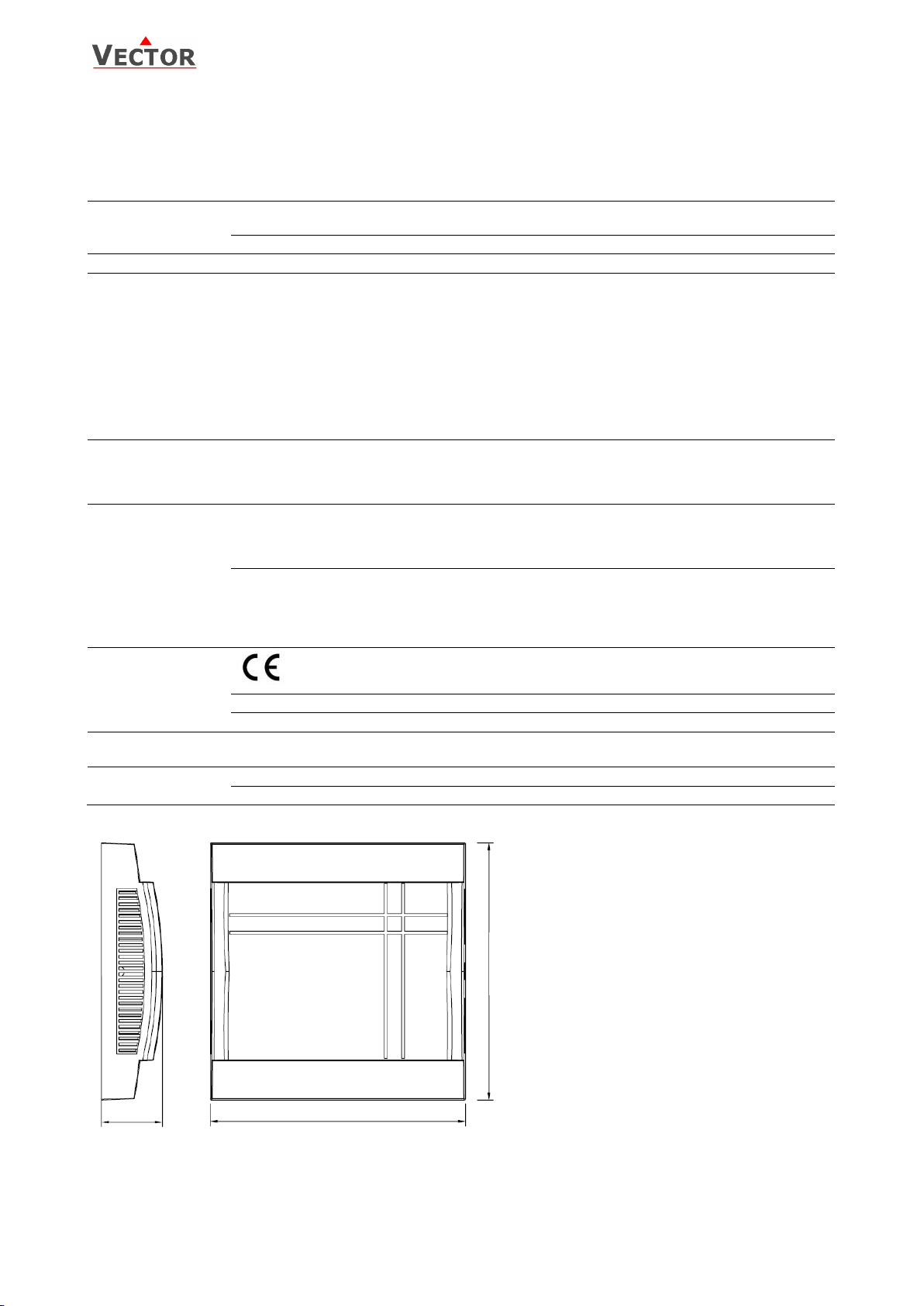
Dimensions (H x W x D)
21 x 88 x 88 mm (0.8” x 3.5” x 3.5”)
Weight (including package)
175 g (6.2 oz.)
88 (3.5)
88 (3.5)
21 (0.8)
Technical specification
Safety advice
This device may only be installed and configured by a skilled electrician. Where a device failure endangers human life
and/or property, it is the responsibility of the client, installer and designer to add additional safety devices to prevent
or detect a system failure caused by such a device failure.
Dimensions mm (inch)
Mounting location
Mount the transmitter on a flat interior wall of the room to be controlled. Do avoid obstructions such as shelves,
curtains and recesses. Do not place near heat sources, draft channels. Do not expose to direct sunlight.
Doc: 70-00-0220, V1.2, 20170131 © Vector Controls GmbH, Switzerland Page 2
Subject to alteration www.vectorcontrols.com
Page 3
SRC-C1
Signal type
JP1
0 – 10 V
(1-2)
0 – 20 mA
(2-3)
Signal range
JP2
0 – 10 V, 0 – 20 mA
(1-2)
2 – 10 V, 4 – 20 mA
(2-3)
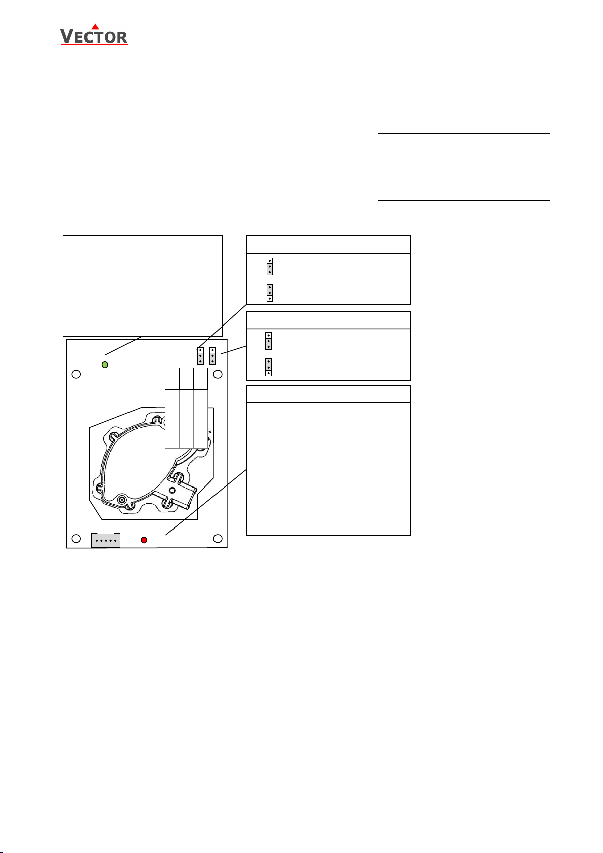
JP1 Signal type
JP2 Signal range
U1: 0-10V
I1: 0-20mA
U1: 2-10V
I1: 4-20mA
3
2
1
3
2
1
U1
0-10V, 2-10V
I1
0-20mA, 4-20mA
3
2
1
3
2
1
Status LED
LED indicates status
No light: no power or unit damaged
5 sec blinking: Normal
Constant light: Error mode
Alternate in 2 sec interval with air
quality LED: Calibration is active.
Calibration end: Constant light for
10s. Success is shown on air quality
led: Green blinking: OK,
Red blinking: failed. Device enters
error mode.
OPA-S
1 2 3
JP1 JP2
STATUS
G 24V
G0 0V
U1/ I1 AO CO2
Air Quality
Air quality LED
LED indicates status
No light : no power or unit damaged
Green : Low CO2 level
Orange : Medium CO2 level
Red : High CO2 level
Red blinking: 0ppm calibration
Green blinking: 400ppm calibration
Mounting instruction
See installation sheet no. 70-000572 (www.vectorcontrols.com).
Configuration
Output signal configuration
The analog output signal type may be configured with a jumper for 0-10
VDC or 0-20 mA control signals. The jumpers are located next to the
terminal connector of each analog output. See table below for jumper
placement. The factory setting is to 0-10 VDC.
The signal range may be set with JP2 for both analog outputs. JP2 will only
operate if the output range specified with OP01 and OP02 is left at the
default position of 0…100%. With any other setting the position of JP2 has
no influence and the range defined with the output parameters applies.
Jumper settings
Doc: 70-00-0220, V1.2, 20170131 © Vector Controls GmbH, Switzerland Page 3
Subject to alteration www.vectorcontrols.com
Page 4
SRC-C1
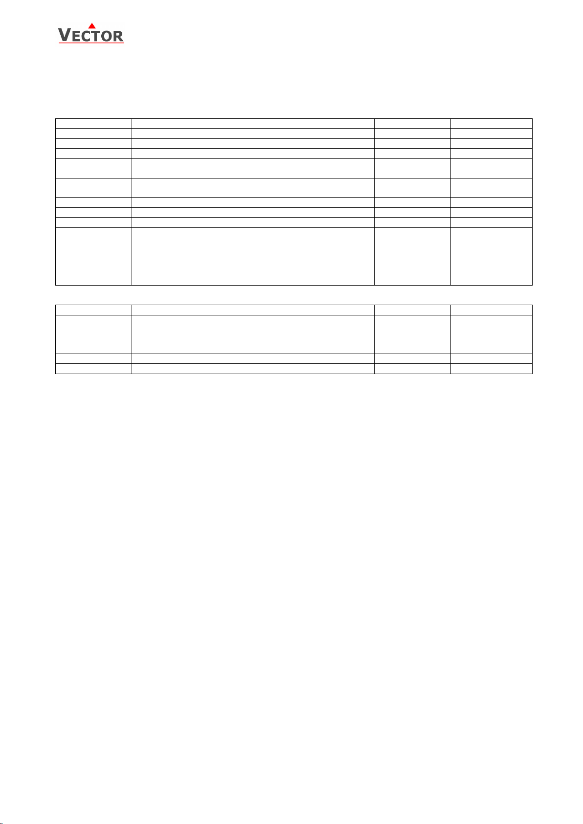
Parameter
Description
Range
Default
IP 00
Enable display of air quality LED on front.
ON, OFF
ON
IP 01
Samples taken for averaging control signal
1…255
10
IP 02
Calibration
-10…10%
0
IP 03
Minimum CO2 range ppm
(concentration when output is at its minimum)
0…5000 ppm
0 ppm
IP 04
Maximum CO2 range ppm
(concentration when output is at maximum)
0…5000 ppm
2000 ppm
IP 05
Level for medium CO2 concentration (orange light)
0…5000 ppm
800 ppm
IP 06
Level for high CO2 concentration (red light)
0…5000 ppm
1500 ppm
IP 07
Enable ABC automatic background calibration
ON, OFF
ON
IP 08
Calibrate CO2 sensor. Note: For normal operation,
calibration is not required. Only experts should calibrate
the sensor.
0 = No calibration (default)
1 = Calibrate to gas (0 ppm)
2 = Calibrate to fresh air (400 ppm)
0..2
0
Parameter
Description
Range
Default
OP 00
AO1: CO2: Configuration of output signal:
0 = Feedback CO2 input,
1 = Feedback CO2 minimum value
2 = Feedback CO2 maximum value
0 – 2
0
OP 01
AO1: CO2: Minimum limitation of output signal
0 – Max. %
0%
OP 02
AO1: CO2: Maximum limitation of output signal
Min. – 100%
100%
Parameter configuration
The transmitter can be adapted to fit perfectly into any application by adjusting the software parameters. The
parameters are set with the operation terminals OPA-S. The OPA-S may also be used as remote indicator. For correct
display version 1.4 of OPA-S is required.
Input configuration
Output configuration
Error messages shown on OPA-S
Err1: Communication error: Verify cable connections, cable type and maximum distance.
Err2: CO2 sensor error: Make sure the sensor is not miss-calibrated. If possible make a 0-ppm or 400 ppm
calibration. (See below). Make sure JP3 is removed or placed in middle position (2-3).
If error cannot be removed by calibrating the sensor, replace product.
Use as P-controller
The CO2-transmitter may be converted into a proportional fresh air controller through a simple change of two
parameter settings:
Set a minimum concentration when the fresh air fan should start to run at its minimum speed; for example 500 ppm.
Set this as the minimum value in IP03 parameter. Then define the value when the fan should run at full speed, for
example 1000 ppm and set this value in IP04. Your transmitter has now been converted into an air quality P-controller!
The fan will start to run if the CO2 concentration is higher than 500 ppm. It increases to its maximum when CO2
concentration reaches 1000 ppm.
Doc: 70-00-0220, V1.2, 20170131 © Vector Controls GmbH, Switzerland Page 4
Subject to alteration www.vectorcontrols.com
Page 5

SRC-C1
Calibration
The default sensor OEM unit is maintenance free in normal environments thanks to the built-in self-correcting ABC
algorithm (Automatic Baseline Correction). This algorithm constantly keeps track of the sensor’s lowest reading over a
7 days interval and slowly corrects for any long-term drift detected as compared to the expected fresh air value of 400
ppm CO2.
Rough handling and transportation might, however, result in a reduction of sensor reading accuracy. With time, the
ABC function will tune the readings back to the correct numbers. The default “tuning speed” is however limited to
about 30 ppm/week. For post calibration convenience, in the event that one cannot wait for the ABC algorithm to cure
any calibration offset, jumper 3 is provided for the operator to choose calibration options. There are two calibration
possibilities: 0 ppm and 400 ppm. Only one calibration needs to be performed.
Calibration to 0 ppm with CO2 free gas
1. Connect the sensor on top with a tube (soft tubing 2 x 4 mm) and
a nipple (nylon tubing 30 x 0.8 x 2.2 mm), see picture on the right
side. There are 2 alternative positions for nipple attachment.
2. Let a gas mixture which is free from CO2 (i.e. Nitrogen or Soda
Lime CO2 scrubbed air) flow into the sensor through the applied
tube. The flow shall be in the range of 0.3 – 1.0 liter/minute during
3 minutes. Keeps the gas mixtures flowing during the whole
procedure.
3. Connect OPA-S, Login and set IP08 = 1 and exit configuration
mode. The air quality LED will blink in red color alternating with
the status led in 2 second intervals.
4. The sensor will now wait for a stable concentration. Once the
calibration has been executed, the status LED will show constant
RED and the green air quality led will blink for 10s if successful. If
calibration is not successful (no stability of concentration for 5 min,
no communication with sensor) the red air quality led will blink
instead and the sensor enters error mode. Recalibrate or restart device to stop error mode.
5. Verify the zero calibration using the OPA-S or the analog outputs. They should show 0 ppm CO2.
6. If zero calibration is not executed (sensor detected unstable gas concentration) wait 10 sec and repeat steps
3 and 4 again. Do not breathe on the sensor!
Calibration to 400 ppm (Fresh air)
1. Expose the active sensor for at least 5 minutes to fresh outside air.
2. Connect OPA-S, Login and set IP08 = 2 and exit configuration mode. The air quality led will blink in green
color alternating with the status led in 2 second intervals.
3. The sensor will now wait for a stable concentration. Once the calibration has been executed, the status LED
will show constant RED and the green air quality led will blink for 10s if successful. If calibration is not
successful (no stability of concentration for 5 min, no communication with sensor) the red air quality led will
blink instead and the sensor enters error mode. Recalibrate or restart device to stop error mode.
4. Verify the calibration using the OPA-S or the analog outputs. They should show 400 ppm CO2.
5. If unsuccessful, wait at least 1 minute before repeating the procedure again. Make sure that the sensor
environment is steady and calm!
Doc: 70-00-0220, V1.2, 20170131 © Vector Controls GmbH, Switzerland Page 5
Subject to alteration www.vectorcontrols.com
 Loading...