

Page 1
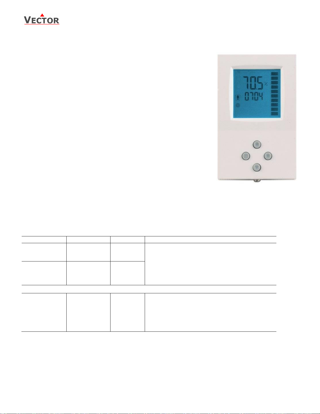
Humidistat TCY-BH-U
Item name
Item code
Variant
Features
TCY-BH-U-W20
TCY-BH-U-W24
TCY-BH-U-W25
40-10 0055-20
40-10 0055-24
40-10 0055-25
standard
humidifying
de-humidifying
Binary controller with:
1 Internal humidity input
1 external temperature input (for setpoint shift)
1 DO (Relay) for humidifier or dehumidifier
1 DO (Relay) for fan (optional)
-W20 = Humidify/dehumidify
Deluxe = 7-day programmable
TCY-BH-U-D-W20
TCY-BH-U-D-W24
TCY-BH-U-D-W25
40-10 0056-20
40-10 0056-24
40-10 0056-25
Deluxe
humidifying
de-humidifying
Accessories
S-Tn10-2
SD-Tn10-12-2
SD-Tn10-20-2
SDB-Tn10-12
SDB-Tn10-20
SOA-Tn10
AES3-HT-A5
40-20 0001
40-20 0002
40-20 0003
40-20 0051
40-20 0004
40-20 0006
40-50 0104
Flying lead sensor with 6 ft cable
Flying lead duct sensor 4.7 inch immersion depth, 6 ft. cable
Flying lead duct sensor 7.8 inch immersion depth, 6ft. cable
Duct sensor with housing, 4.7 inch immersion depth
Duct sensor with housing, 7.8 inch immersion depth
Outdoor sensor
Replacement humidity sensor 5% accuracy
TCY-BH-U Humidistat
Features
Control for binary humidifiers and dehumidifiers with or without fan support.
Low power energy consumption: < 1W per unit
Relays switching for outputs each up to 300W
Cost saving option with Economy functionality and setpoint limitations
External sensor input for setpoint setback based on outdoor temperature
Password protected programmable user and control parameters
o Setpoint range limitation
o Access control for setpoints and mode change
o Access control for clock and time programs
o Select your display contents
o Selectable behavior after return from power failure
Temperature display of external input in Celsius or Fahrenheit
Deluxe version:
Clock and time schedule functions
Blue backlight for LCD
Applications
Humidifiers:
o On / Off type humidifiers
o On / Off type humidifiers with single speed fan support
Dehumidifiers:
o On / Off type dehumidifiers
o On / Off type dehumidifiers with single speed fan support
Combination humidifiers and dehumidifiers without fan support
General description
The TCY-BH-U is a stand-alone electronic binary humidity stat. The TCY-BH-U features one internal humidity sensor, one external
NTC temperature sensor input and two binary outputs (Relays).
A detailed parameterization is possible with the use of a simple configuration routine. The TCY-BH-U can be configured using the
standard operation terminal. No special tools or software is required.
Ordering
Selection of devices and sensors
External temperature sensors: Use only our approved NTC sensors to achieve maximum accuracy. Recommended is SDB-Tn1015 as duct sensor and SOA-Tn10 as outdoor sensor.
Binary auxiliary devices: E.g. humidifiers, de-humidifiers and fans. Do not directly connect devices that exceed 2(1.2)A. Observe
startup current on inductive loads!
Doc: 70-07-0102, V1.4, 20160215 © Vector Controls GmbH, Switzerland Page 1
Subject to alteration www.vectorcontrols.com
Page 2
Humidistat TCY-BH-U
Power supply
Operating voltage
24 V AC/DC ± 10 %, 50…60 Hz
Power consumption
Max. 1.5 VA
Electrical connection
Terminal connectors,
wire 0.34…2.5 mm2 (AWG 24…12)
Deluxe type only:
Power backup for real time clock
Min 48h if charged for 24h
Signal inputs
Humidity input:
Range
Accuracy
Hysteresis
Element: Polymer-Based Capacity Sensor
0…100 % r.H.
10%...90% r.H. 5.0 %
0…10% and 90…100% 7.0 %
±1% r.H.
Temperature input
Range
External NTC (Sxx-Tn10 sensor):
-40…70 °C (-40…158 °F)
Accuracy
-40…0 °C (-40…32 °F): 0.5 K
0…50 °C (32…122 °F): 0.2 K
50…70 °C (122…158 °F): 0.5 K
Signal outputs
Digital switching outputs
Switching type
AC Switching power
DO1…DO2
Relays
2(1.2) A, 250VAC (max fan power 300W)
Environment
Operation
Climatic conditions
Temperature
Humidity
To IEC 721-3-3
class 3 K5
0°C …50°C (32°F…122°F)
<95% R.H. non-condensing
Transport & storage
Climatic conditions
Temperature
Humidity
Mechanical conditions
To IEC 721-3-2 and IEC 721-3-1
class 3 K3 and class 1 K3
-25°C…70°C (-13°F…158°F)
<95% R.H. non-condensing
class 2M2
Standards
conform according to
EMC Standard 89/336/EEC
EMEI Standard 73/23/EEC
EN 61 000-6-1/ EN 61 000-6-3
Product standards
Automatic electrical controls for
household and similar use
Special requirement on humidity
dependent controls
EN 60 730 –1
EN 60 730 – 2 - 9
Degree of protection
IP30 to EN 60 529
Safety class
III (IEC 60536)
Housing
Cover, back part
Mounting plate
Fire proof ABS plastic (UL94 class V-0)
Galvanized steel
General
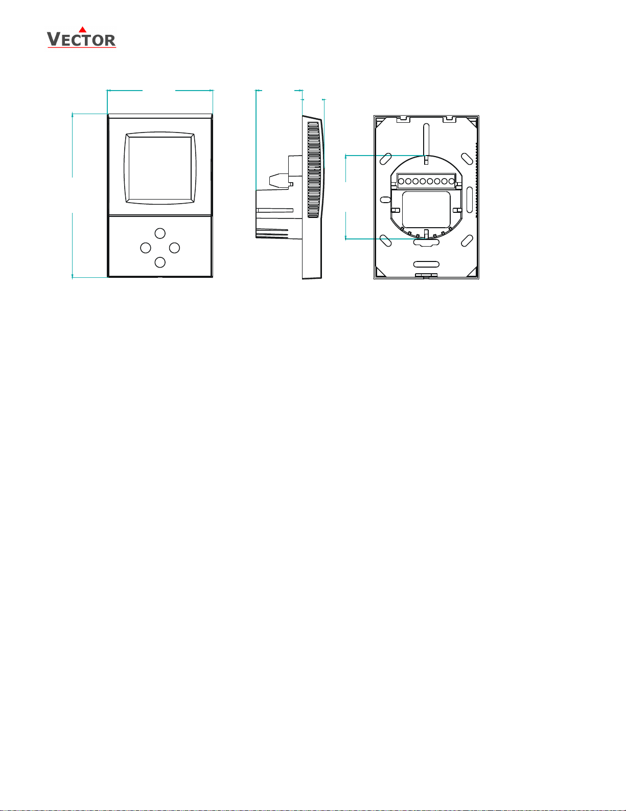
Dimensions (H x W x D)
Front part:
Power case:
112 x 73 x 15 mm (4.4” x 2.9” x 0.6”)
ø 58 x 32 mm (ø 2.3” x 1.3”)
Weight (including package)
270g
Technical specification
Doc: 70-07-0102, V1.4, 20160215 © Vector Controls GmbH, Switzerland Page 2
Subject to alteration www.vectorcontrols.com
Page 3
Humidistat TCY-BH-U
58 (2.3)
112 (4.4)
73 (2.9)
32 (1.2)
15
(0.6)
Dimensions mm (inch)
Doc: 70-07-0102, V1.4, 20160215 © Vector Controls GmbH, Switzerland Page 3
Subject to alteration www.vectorcontrols.com
Page 4

Humidistat TCY-BH-U
CP10
YB1 DO1
YB2 DO2
RT
CP10 = 0
Humidify
Dehumidify
Temperature input for
setback
NTC 10kΩ @ 25°C (77°F)
CP10 = 1
Humidify
CP11 = ON: FAN
CP10 = 2
If CP11 = ON: FAN
Dehumidify
0…250VAC
0V (GND)
24V AC
2
TCY-BH-U
1
3
Q13
7 8
R
T
5
Q23
YB1
4
Q14
YB2
6
Q24
Installation and safety advice
Caution! This device is intended to be used for comfort applications. Where a device failure endangers human life and/or
property, it is the responsibility of the owner, designer and installer to add additional safety devices to prevent or detect a system
failure caused by such a device failure. Vector Controls or its affiliates cannot be held liable for any damage caused by such a
failure. Failure to follow specifications and local regulations may endanger life, cause equipment damage and void warranty.
Wiring diagram
Description:
Connections depend on parameter CP10 and CP11! (See page 10)
Mechanical design and installation
The unit consists of two parts: (a) The power case with attached mounting plate and (b) the front part.
Mounting location
On an easy accessible interior wall, approx. 1.5 m (4.5’) above the floor in an area of average temperature.
Avoid exposure to direct sunlight or other heat sources, e.g. the area above radiators and heat emitting electrical
equipment.
Avoid locations behind doors, outside walls and below or above air discharge grills and diffusers.
Location of mounting is less critical if external temperature sensors are used
Installation
1. Connect the wires to be connected to the terminals of the power case according to wiring diagram
2. Install the mounting plate to the flush mounting box. Make sure that the nipple with the front retaining screw is at the
bottom. Make sure the mounting screw heads do not stand out more than 5 mm (0.2”) from the surface of the mounting
plate.
3. Ensure that the jumpers are set correctly.
4. Slide the two latches located on the top of the front part into the hooks at the upper side of the mounting plate.
5. Carefully lower the front part until the interconnector reaches the mounting-plate. Continue pressing in a gentle way
until the front part is fully connected. While inserting the connectors, a slight resistance can be felt. This is normal. Do
not use excessive force!
6. With a Philips-type screw driver of size #2, carefully tighten the front holding screw to secure the front part to the
mounting plate. This screw is located on the front lower side of the unit. There is no need to tighten the screw too much.
Doc: 70-07-0102, V1.4, 20160215 © Vector Controls GmbH, Switzerland Page 4
Subject to alteration www.vectorcontrols.com
Page 5

Humidistat TCY-BH-U
Operation mode and state indication
Comfort (occupied)
All control functions operating per setpoints.
Economy (unoccupied):
Setpoints shifted according to Parameters CP04.
Economy mode and setpoint shift may be disabled with UP04
OFF
Energy hold Off
Outputs are off, inputs monitored for alarm condition
Fan active
Fan is running
Temperature setback
Temperature setback is active and shifts setpoint
Left (POWER)
parameter change)
Up
and parameters)
Down
Mode
Display of operation
mode
Large Digits
value.
Indicators
1 Temperature
setback error
Vertical Bar
Scrolls down = dehumidifying
Small Digits
Right (OPTION)
parameter change)
Display and operation
Increment SETPOINT
(Parameter setting:
SCROLL menu options
Press < 2 sec.: Toggle STANDBYCOMFORT mode or switch from OFF
to ON
Press > 2 sec.: Turn unit OFF. Text
OFF displayed with current time
(deluxe) temperature (standard)
(Parameter setting: ENTER to
select menu option, accept
Display of input or parameter
Display of setpoint, clock or
parameter number.
Scrolls up = humidifying
Press < 2 sec.: Switch display
Press > 2 sec.: Access time
programs, change time.
(Parameter setting: ENTER to
select menu option, accept
Decrement SETPOINT
(Parameter setting: SCROLL menu
options and parameters)
Power failure
All the parameters and setpoints are memorized and don’t need to be reentered. Depending on Parameter UP-03 the unit will
remain switched off, switch on automatically or return to the operation mode it was in before the power failure.
The deluxe version includes a real time clock with a 48h backup battery powered through a super capacitor. The time does not
need to be re-entered after a power failure.
Error messages
The TCY-BH-U may display the following error condition:
Err1: Humidity sensor faulty. The humidity sensor is damaged or removed. Verify if sensing element!
Err2: External input for temperature setback missing or damaged.
Doc: 70-07-0102, V1.4, 20160215 © Vector Controls GmbH, Switzerland Page 5
Subject to alteration www.vectorcontrols.com
Page 6

Humidistat TCY-BH-U
Name on display
Function
Override reset
no
Switching event not used
OFF
Operation mode changes to off mode
Reset is active
ECO
Operation mode changes to economy mode
Reset is active
ON
Operation mode changes to comfort mode
Reset is not active
UNI
Operation mode does not change
Reset is not active
Advanced user setup menu
To enter the advanced user setup menu, activate the controller by pressing the POWER button. Press the ENTER key for 3 sec
until SEL is shown in the large digits. The menu can be left by pressing the POWER / ESC button or by not pressing a button for
more than 5 minutes.
Sensor calibration
Start the advanced menu as described above. Select CALH or CALt with the UP/DOWN buttons.
Small digits show CALH (internal humidity sensor calibration) and CALt (temperature setback sensor calibration). The current
calibration value is displayed. Press ENTER and then change the value with the UP/DOWN buttons, and save it with the ENTER
button.
Clock setup (for deluxe versions only)
A blinking clock indicates that the time needs to be set. Time programs will not operate if the time is not defined.
Start advanced menu as described above and select the clock display by pressing the UP or DOWN keys.
The current time is now displayed in the small digits. Press the ENTER button to enter the clock setup. The minute digits start
to blink and can be changed with the UP/DOWN buttons.
Pressing ENTER saves minutes and steps to hours. The hour digits blink now and can be changed with the UP/DOWN buttons.
Press ENTER again to step to the day setting. DAY1-7 is displayed. Day 1 stands for Monday, Day 2 for Tuesday and so forth.
Select the day according to current weekday.
Pressing ENTER again saves the settings and moves back to the SELECT menu. To leave the setup mode press the POWER
button.
Time schedules (for deluxe versions only)
Four individual time programs (Pro1, Pro2, Pro3, Pro4), each with four switching events, are available. A switching event changes
the controller from one operation mode to another.
Time schedules and their switching events can be individually enabled. Make sure that undefined time schedules and switching
events are disabled.
Enter the advanced menu as described above and select PRO by pressing UP or DOWN buttons. Press the ENTER key.
Pro1 is now shown in the large digits, while the number 1 is blinking. Select time schedule Pro1-Pro4 by using UP/DOWN keys
and pressing the ENTER key.
1) Enable or disable the Pro1 time schedule. Choose ON or OFF with the UP/DOWN keys. The following steps will only be
accessible if ON is selected. OFF disables this time schedule and its switching events.
2) Select day(s) with UP/DOWN. Day 1 stands for Monday, day 2 for Tuesday and so forth. Options are d1-7, d1-6, d1-5, d6-7,
day1, day2, day3, day4, day5, day6, day7. This time schedule will be active during the selected day or days. Press ENTER to
continue.
3) Select desired operation mode below with UP/DOWN, press ENTER to continue
4) Select switching time 00:00 to 23:45 in 15-minute steps with UP/DOWN.
5) Press ENTER to continue and repeat step 3 and 4 for each switching event.
UNI: University mode: This switching mode is used for rooms such as lecture rooms and auditoriums that might be occupied
during a certain time. During this time the reset is not active. The unit will not start itself when UNI mode is active. It still needs
to be manually activated. This is to avoid unnecessary heating or cooling of such rooms while they are not occupied.
Override reset function: The override reset applies when the unit is manually switched on, while in scheduled off or ECO mode.
The unit will return to the scheduled mode when the reset time defined in UP08 expires.
Setting UP08 to 0 disables the override reset.
Example
From Monday to Friday the controller shall be in Comfort mode between 08:00 in the morning and 18:00 in the evening. Between
18:00 and 08:00 it shall be in OFF mode. One time schedule with two switching events is required to achieve this time schedule:
Setting procedure:
Select the desired time schedule (Pro1) with UP/DOWN key,
Press enter, select ON to activate Pro1 with UP/DOWN keys, Press enter,
Select d1-5 (Monday – Friday) with UP/DOWN keys and confirm with ENTER key
Select ON mode with UP / DOWN key and confirm with ENTER
Select the time of the first desired switching event for Pro1 (ON mode) to 08:00 with the UP/DOWN keys;
Press ENTER to conclude this switching event (first of 4 available).
Doc: 70-07-0102, V1.4, 20160215 © Vector Controls GmbH, Switzerland Page 6
Subject to alteration www.vectorcontrols.com
Page 7

Humidistat TCY-BH-U
Parameter
Description
Setting Range
Factory Setting
UP 00
Enable change of operation modes
ON, OFF
ON (Enabled)
UP 01
Enable change of setpoints
ON, OFF
ON (Enabled)
UP 02
Enable access to Time programs
ON, OFF
ON (Enabled)
UP 03
State after power failure:
0 = Switched OFF, 1 = Switched ON, 2 = state before power failure
0, 1, 2
2
UP 04
Enable Economy functionality
ON, OFF
OFF (Disabled)
UP 05
Celsius or Fahrenheit, Select ON for Fahrenheit, OFF for Celsius
ON, OFF
OFF (Celsius)
UP 06
Select contents of small digits in standard mode:
00 = OFF
01 = Setpoint
02 = Humidity Sensor
03 = External Temperature Sensor
04 = Clock
0…5
04 Deluxe:
show clock
01 Standard:
show setpoint
UP 07
New: Resolution 0.5% or 1% RH
OFF = Display resolution is 0.5% RH
ON = Display resolution is 1% RH
ON, OFF
OFF (0.5% RH)
UP 08
Deluxe only
Clock display type:
OFF = Show 24hour clock
ON = Show 12hour clock (AM, PM)
ON, OFF
OFF (24h)
UP 09
Deluxe only
Reset timer for override mode: Only available for deluxe version
0 = Reset of override mode is not active.
1…255 = delay in minutes to return to scheduled operation if the
device is activated while scheduled to be in OFF or ECO
mode.
0…255
60 (Min)
Configuration parameters
The TCY-BH-U is preset to work for most applications. For special requirements it can be fine-tuned to work ideally with a simple
parameter setup routine. The parameters can be changed on the unit without the need of additional equipment.
Identifying the firmware version
The parameters and functionality of controller depend on its firmware version and revision. It is therefore important to use a
matching product version and parameter set. The Firmware version and revision version can be found when pressing
simultaneously the and keys during several seconds. On the upper 7 segment display, the firmware version can be found,
on the lower 7 segment display the current revision index (or “sub-version”).
Access to parameters
The TCY-BH-U is an intelligent controller and can be adapted to fit perfectly into your application. The control operation is defined
by parameters. The parameters are set during operation by using the standard operation terminal.
The parameters are password protected. There are two levels of parameters: User operation parameters for access control
settings and Expert parameters for control functions and unit setup. The passwords for user levels and expert levels are different.
Only control experts should be given the control parameter password.
The parameters can be changed as follows:
1. Press UP and DOWN button simultaneously for three seconds. The display will indicate the firmware version in the upper
large digits and the revision in the lower small digits. Pressing any key will show: CODE.
2. Select a password using UP or DOWN buttons. Select 009 in order to get access to the user parameters, 241 for controls
parameters.
Press OPTION after selecting the correct password.
3. Once logged in, the parameter is displayed immediately
4. Select the parameters with the UP/DOWN keys. Change a parameter by pressing the OPTION key. The MIN and MAX
symbols show up and indicate that the parameter may be modified now. Use UP and DOWN key to adjust the value.
5. After you are done, press OPTION or POWER in order to return to the parameter selection level.
6. Press the POWER key again so as to leave the menu. The unit will return to normal operation if no key is pressed for
more than 5 minutes.
User parameters (code 009)
Doc: 70-07-0102, V1.4, 20160215 © Vector Controls GmbH, Switzerland Page 7
Subject to alteration www.vectorcontrols.com
Page 8

Humidistat TCY-BH-U
Parameter
Description
Range
Standard
CP 00
Minimum setpoint limit in humidification mode
0…100%
10%
CP 01
Maximum setpoint limit in humidification mode
0…100%
90%
CP 02
Minimum setpoint limit in de-humidification mode
0…100%
10%
CP 03
Maximum setpoint limit in de-humidification mode
0…100%
90%
CP 04
Economy humidity shift:
The comfort (occupied) setpoint is shifted by the value set here. If humidifying
is active the comfort setpoint will be decreased, if dehumidifying is active, the
setpoint will be increased. (Enable with UP04.)
0…100%
10%
CP 05
This parameter is only used if CP10 = 0
Dead zone span:
The Dead Zone Span defines the deviation setpoint to input value required for
the controller to switch from humidifying to dehumidifying or vice versa. The
output is off while the measured value is within the dead zone span. A
negative dead zone is not possible.
0…100%
10%
CP 06
This parameter is only used if CP10 = 0
Delay on humidify – de-humidify change over
0…255 min
5 min
CP 07
Switching Hysteresis
Defines the difference between switching on and switching off an output. A
small hysteresis will increase the number of switching cycles and thus the wear
on associated equipment.
0…100%
3%
CP 08
Delay OFF (Minimum running time) [MM:SS]
Prevents a too short running cycle for the control output by setting a minimum
running time
00:00 to 98:30
00:10s
CP 09
Delay ON (Minimum stopping time) [MM:SS]
Prevents a too short running cycle for the control output by setting a minimum
stopping time
00:00 to 98:30
00:10s
CP 10
Configuration of control mode
0 = Both Humidification and de-humidification
1 = W04 = Humidification only
2 = W05 = De-humidification only
0 - 2
TCY-BH-U: 0
TCY-BH-U-W4: 1
TCY-BH-U-W5: 2
CP 11
Enable fan (only if CP 10 ≠ 0)
ON, OFF
TCY-BH-U: OFF
TCY-BH-U-W4: ON
TCY-BH-U-W5: ON
CP 12
Start delay for fan [MM:SS]
(Time the fan runs before control output starts)
00:00 – 98:30
00:10
CP 13
Stop delay for fan [MM:SS]
(Time the fan keeps running after control output stops)
00:00 – 98:30
01:30
System type
CP10
CP11
DO1
DO2
Humidify and de-humidify
0
OFF
Humidifying
Dehumidifying
Humidify only
1
OFF
Humidifying
OFF
Humidify with fan
1
ON
Humidifying
FAN
De-humidify only
2
OFF
OFF
Dehumidifying
De-humidify with fan
2
ON
FAN
Dehumidifying
Controls Output
Fan Output
Demand
CP12
CP13
Time [s]
Control functions (code 241)
Warning! Only experts should change these settings! See user parameters for login procedure.
Controls configuration
Output configuration
Control logic TCY-BH-U
Fan delay
Once there is an output demand, the humidistat will first activate the fan, wait the required start delay time (CP12)
and then activate the control output. This will ensure stable air for humidification or de-humidification.
The control output will be switched off when the setpoint is reached. The fan keeps running until stop delay (CP13) has
expired. This will ensure that no left over humidity remains in the device or its ducts.
Doc: 70-07-0102, V1.4, 20160215 © Vector Controls GmbH, Switzerland Page 8
Subject to alteration www.vectorcontrols.com
Page 9

Humidistat TCY-BH-U
CP 14
OFF = Temperature setback is disabled
ON = Temperature setback is enabled
ON, OFF
OFF
CP 15
Setpoint limit at full setback
0…100%
20%
CP 16
Lower temperature limit:
Outside temperature with maximum setback
The setpoint will be equal to the minimum setpoint limit
-40…60°C
-40…160°F
-30°C (-22°F)
CP 17
Upper temperature limit:
Outside temperature at begin of setback.
-40…60°C
40…160°F
0°C (32°F)
CP 18
Number of seconds taken into account to calculate the averaging input
signal.
Low value = fast response
High value = slow response
0…100
10
Temperature setback
T [°C, F]
CP16
CP17
CP15
Setpoint
W
Input configuration
Temperature setback (TSET)
Shift the humidity setpoint towards a defined TSET setpoint CP15 depending on the outdoor temperature.
Temperature setback becomes active when the outside temperature drops below the activation limit of temperature
setback CP17. The full temperature setback is reached when the temperature reaches the full limit CP16. The actual
setpoint will in this case be equal to the TSET setpoint.
Temperature setback may be enabled with CP14.
Averaging function of input signal:
The averaging function is used to prevent unwanted fluctuation of sensor signals. The controller measures every
second the signal inputs. The input signal is built over a number of measured values. Select how many values should
be used to calculate the averaging signal. Control speed will slow down when a large number of samples are used for
an averaging signal. This should be taken into account when defining the control parameters.
Doc: 70-07-0102, V1.4, 20160215 © Vector Controls GmbH, Switzerland Page 9
Subject to alteration www.vectorcontrols.com
 Loading...