

Page 1
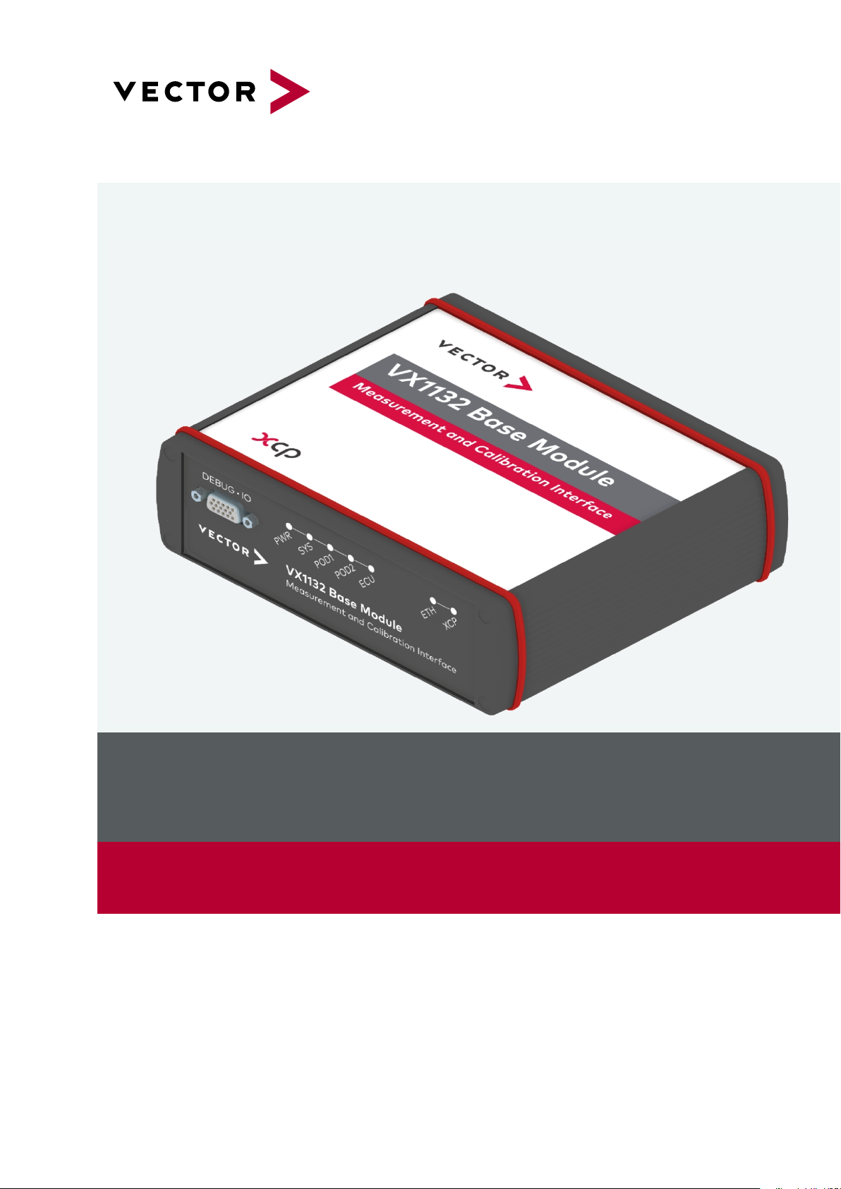
VX1000
System Manual
Version 3.3.0 | English
Page 2

Imprint
Vector Informatik GmbH
Ingersheimer Straße 24
D-70499 Stuttgart
The information and data given in this user manual can be changed without prior notice. No part of this manual may be reproduced in any
form or by any means without the written permission of the publisher, regardlessof which method or which instruments, electronicor mechanical,are used. All technical information, drafts, etc. are liableto law of copyright pr otection.
© Copyright 2016, Vector Informatik GmbH. All rights reserved.
Page 3

Contents
Contents
1 Introduction 5
1.1 About this User Manual 6
1.1.1 Certification 7
1.1.2 Warranty 7
1.1.3 Support 7
1.1.4 Registered Trademarks 7
2 System Overview 8
2.1 Overview 9
2.2 VX1000 System Components 10
2.3 Supported Microcontrollers 11
2.4 Features 12
2.5 VX1000 Application Driver and VX1000If 13
3 VXtools 14
3.1 VXtools Setup 15
3.1.1 Overview 15
3.1.2 Minimum Requirements 15
3.1.3 Installations Instructions 15
3.2 VXconfig 16
3.2.1 General Information 16
3.2.2 Menu Bar 17
3.2.3 Toolbar 20
3.2.4 Status Bar 21
3.2.5 Device List View 21
3.3 VXupdate 23
3.3.1 General Information 23
3.3.2 Menu Bar 23
3.3.3 Toolbar 25
3.3.4 Status Bar 25
3.3.5 Device List View 26
3.3.6 VX configuration Selector 27
3.3.7 Image List View 28
3.3.8 Flash Update 28
3.4 VXconsole 29
3.4.1 General Information 29
3.4.2 Toolbar 29
3.4.3 Command Bar 30
VX1000
System Manual
Version 3.3.0 3
Page 4

Contents
3.4.4 Status Bar 30
3.4.5 Message Window 30
3.5 HowTo 32
3.5.1 VXtools Installation 32
3.5.2 VX1000 System Installation 32
3.5.3 VX1000 System IP Configuration 33
3.5.3.1 Change IPAddress 34
3.5.3.2 Force IP Address 35
3.5.4 FPGA and Firmware Update 35
3.5.5 Write VXparameter File to VX device 36
4 XCP Slaves 39
4.1 General Information 40
4.2 XCP Protocol Parameters 40
4.3 XCP Command Matrix 41
VX1000
System Manual
Version 3.3.0 4
Page 5

1 Introduction
1 Introduction
In this chapter you find the following information:
1.1 About this User Manual 6
1.1.1 Certification 7
1.1.2 Warranty 7
1.1.3 Support 7
1.1.4 Registered Trademarks 7
VX1000
System Manual
Version 3.3.0 5
Page 6
1 Introduction
1.1 About this User Manual
Conventions In the two following charts you will find the conventions used in the user manual
regarding utilized spellings and symbols.
Style Utilization
bold Blocks, surface elements, window- and dialog names of the soft-
ware. Accentuation of warnings and advices.
[OK]
File|Save
Microsoft Legally protected proper names and side notes.
Source Code
Hyperlink Hyperlinks and references.
<CTRL>+<S> Notation for shortcuts.
Symbol Utilization
File name and source code.
This symbol calls your attention to warnings.
Push buttons in brackets
Notation for menus and menu entries
Here you can obtain supplemental information.
Here you can find additional information.
Here is an example that has been prepared for you.
Step-by-step instructions provide assistance at these points.
Instructions on editing files are found at these points.
This symbol warns you not to edit the specified file.
VX1000
System Manual
Version 3.3.0 6
Page 7

1.1.1 Certification
1 Introduction
Certified Quality
Management System
Vector Informatik GmbH has ISO 9001:2008 certification. The ISO standard is a globally recognized standard.
1.1.2 Warranty
Restriction
of warranty
We reserve the right to change the contents of the documentation and the software
without notice. Vector Informatik GmbH assumes no liability for correct contents or
damages which are resulted from the usage of the documentation. We are grateful for
references to mistakes or for suggestions for improvement to be able to offer you
even more efficient products in the future.
1.1.3 Support
You need support? You can get through to our support at the phone number
+49 711 80670-200 or by fax
+49 711 80670-111
E-Mail: VXsupport@vector.com
1.1.4 Registered Trademarks
Registered
trademarks
All trademarks mentioned in this documentation and if necessary third party
registered are absolutely subject to the conditions of each valid label right and the
rights of particular registered proprietor. All trademarks, trade names or company
names are or can be trademarks or registered trademarks of their particular proprietors. All rights which are not expressly allowed are reserved. If an explicit label of
trademarks, which are used in this documentation, fails, should not mean that a name
is free of third party rights.
> Windows, Windows 7, Windows 8.1, Windows 10
are trademarks of the Microsoft Corporation.
VX1000
System Manual
Version 3.3.0 7
Page 8

2 System Overview
2 System Overview
In this chapter you find the following information:
2.1 Overview 9
2.2 VX1000 System Components 10
2.3 Supported Microcontrollers 11
2.4 Features 12
2.5 VX1000 Application Driver and VX1000If 13
VX1000
System Manual
Version 3.3.0 8
Page 9
2 System Overview
2.1 Overview
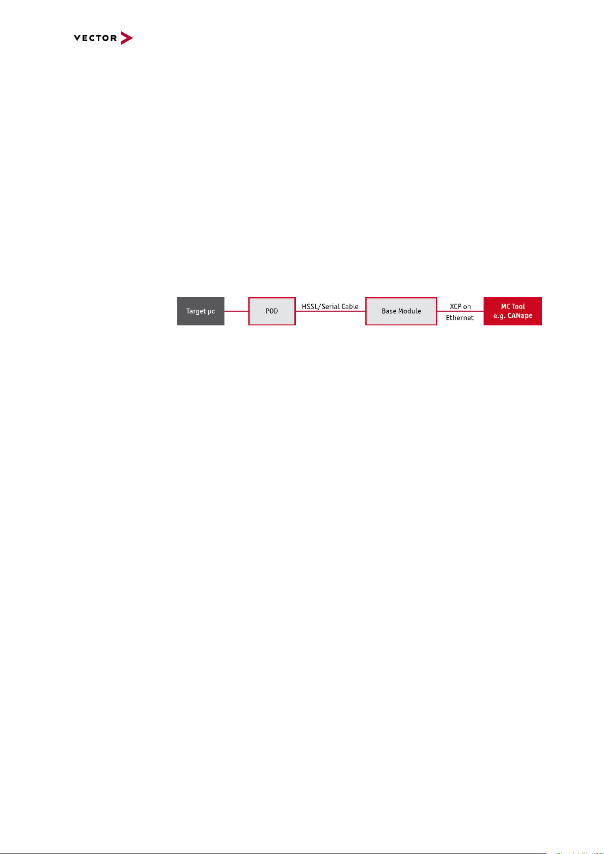
At a glance The VX1000 System is a scalable solution with top performance for your meas-
urement and calibration tasks. It can be used in the vehicle – both in the interior and in
the engine compartment – on test benches and in the laboratory. The system forms
the interface between the ECU and a measurement and calibration tool such as
CANape. For high data throughput with minimal impact on ECU run-time, data is
accessed over the microcontroller-specific data trace and debug ports.
The VX1000 base module is connected to the PC over XCP on Ethernet, an OEM-
independent ASAM standard (www.asam.net) that is widely used in the automotive
industry. The VX1000 measurement hardware is connected to the ECU via a POD
(Plug-On device). Depending on the available microcontroller interface, either the data
trace or a copying method can be used to acquire measurement data.
The hardware components like Base Modules, PODs, Cables and Adapters are
described in separate documents. These documents are available in the Vector Download Center.
Modular concept
The modular concept of the VX1000 System allows connecting to different microcontrollers.
The VX1000 System consists of the following components:
> VX1000 Base Modules
> VX1300 Cables (HSSL/Serial Cable)
> VX1400/VX1500 Plug-On Devices (POD)
Target connection To support longer distances between the VX1000 Base Module and the target ECU,
e.g. under the hood in a car, the Base Module is connected to the ECU via a POD and
a cable that is available in different lengths. PODs and cables are designed to withstand rough automotive environmental conditions.
Advantages Advantages of the VX1000 System are:
> Powerful measurement and calibration access to internal ECU data with max-
imum transmission rates
> Very small POD to connect to the ECU debug interface
> Easy and quick integration into the ECU software
> No impact on ECU run-time with data trace measurement method
> Interface to numerous development tools by third-party suppliers via the stand-
ardized ASAM protocol XCP on Ethernet
> Special functions for engine controllers such as Calibration Wake-Up and Cal-
ibration RAM Supply
VX1000
System Manual
Version 3.3.0 9
Page 10
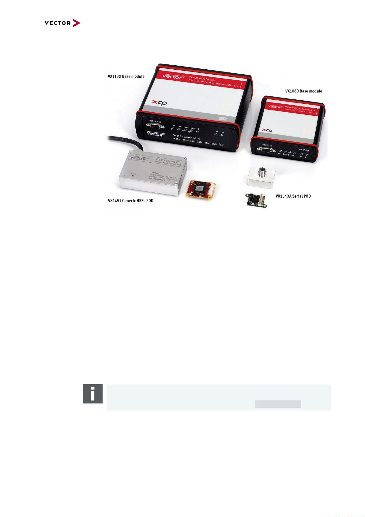
2.2 VX1000 System Components
2 System Overview
Base Modules > VX1060 Serial Base Module
> VX1132 Base Module
Plug-On Devices
(PODs)
Cables > VX131x Cables for VX1544 Serial PODs
Adapters > VX19xx Target connection adapters
Infrastructure
Hardware
> VX1451 Generic HSSL POD (RTP/DMM, Nexus AUX)
> VX1453 Generic HSSL POD (Nexus Aurora)
> VX1543A Serial POD (Infineon, DAP, JTAG)
> VX1544A/B Serial POD (Infineon, DAP/DAP2, JTAG, HSCT, Zipwire)
> VX134x Cables and Cable Pigtails for VX154x Serial PODs
> VX136x CAN Cables for Base Modules
> VX137x Cables and Cable Pigtails for VX145x HSSL PODs
> VX199x Debugger Adapters
> VX0312 Ethernet/CAN Interface
Note
The VX1000 System Components are described in the poster “VX1000 System
Components”. The poster can be downloaded from the Vector homepage.
VX1000
System Manual
Version 3.3.0 10
Page 11

2.3 Supported Microcontrollers
2 System Overview
Supported microcontrollers
Serial PODs The following target microcontrollers are supported by the VX154x Serial PODs:
This section contains a list of all currently supported microcontroller families.
Note
Please contact Vector VX support (VXsupport@vector.com) for further information
about supported microcontrollers and implemented features.
Infineon:
> TriCore TC1xxx (ED) via DAP
> TriCore AURIX TC2xx (ED) via DAP2 or HSCT
> TriCore AURIX TC3xx (ED) via DAP2 or HSCT
> XC2000 via DAP
NXP (Freescale)/STM
> PowerPC xPC5xxx via Nexus JTAG Class 2+ or Zipwire
Renesas
> RH850 via Nexus JTAG Class 2+
> V850E2 via Nexus JTAG Class 2+
HSSL PODs The following target microcontrollers are supported by the VX145x HSSL PODs:
Infineon
> TriCore AURIX TC2xx ED via Aurora
> TriCore AURIX TC3xx ED via Aurora
NXP (Freescale)/STM
> PowerPC xPC5xxx via Nexus AUX
> PowerPC MPC57xx via Nexus Aurora
Renesas
> RH850 via Nexus Aurora
Texas Instruments
> TMSx70 via RTP/DMM
VX1000
System Manual
Version 3.3.0 11
Page 12

2 System Overview
2.4 Features
Overview > Very high measurement data throughput of up to 50 MByte/s with the data trace
measurement method and up to 3 MByte/s with the copying method
> Measurement of fast signal cycles (>10 µs for data trace, >40 µs for copying
method)
> Measurement configurations with more than 100,000 signals can be processed
> Precise generation of DAQ time stamps in the ECU
> ECU cold start measurement (First Loop DAQ)
> Calibration of ECU parameters without address range limitations
> Calibration memory page switching
> Automatic overlays when calibrating parameters in flash memory
> Stimulation or bypassing with short latency times
> 100/1000 Mbit/s Ethernet connection to the PC
> Galvanically isolated power supply with wide input voltage range
> POD power supply via the VX1000 Base Module
> Optional: Flash programming, even for “brain-dead” ECUs
> Optional: 1 x FlexRay for bus monitoring and 4 x CAN via XL Driver Library inter-
face for CANape/CANalyzer/CANoe and custom applications
> PC tools for easy configuration and for software updates
> Connector on the VX1000 Base Module to loop through a target debugger
Reference
Detailed performance information of the VX1000 System in combination with spe-
cific target microcontrollers can be found in the VX1000 Product Information. The
VX1000 Product Information can be downloaded from the Vector homepage.
VX1000
System Manual
Version 3.3.0 12
Page 13
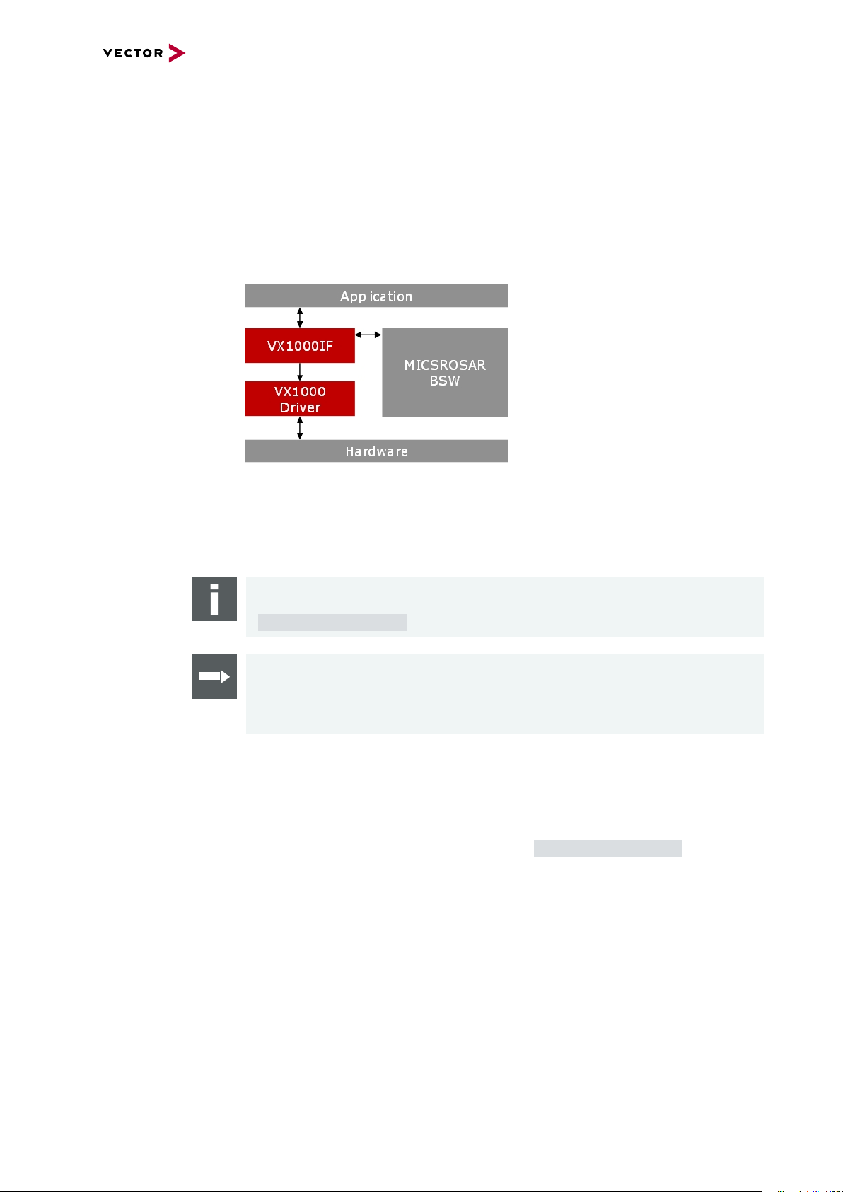
2.5 VX1000 Application Driver and VX1000If
For the VX1000 Measurement and Calibration System, the VX1000 Application Driver
must be integrated into the ECU application.
The VX1000 Application Driver contains highly configurable, platform- and derivative-
specific code that has not been developed and tested for use in series software
releases.
For this reason, the platform-neutral VX1000If component was additionally developed,
which encapsulates the VX1000 Application Driver and serves to reliably isolate the
VX1000 Application Driver API in series software releases.
2 System Overview
Every VX1000 Application Driver comes with the VX1000If component. All doc-
umentation describes explicitly the use of the VX1000 Application Driver through the
VX1000If API. Use of the VX1000 Application Driver without VX1000If is not intended.
Note
The VX1000 Application Driver is provided as an installer that can be requested via
VXsupport@vector.com.
Reference
The integration of the VX1000 Applicaton Driver and VX1000If is described in the
target specific VX1000 Getting Started application notes. The application notes are
included in the VX1000 Application Driver Setup.
Legal Please note that the terms and conditions under which the VX1000 Application Driver
and the VX1000If component are delivered as standard exclude the use in series software releases.
For deliveries of the VX1000If component via a Vector PES software integration package, on the other hand, special contract conditions apply, including for use in series
software releases. You will receive details from VXsupport@vector.com.
Technically, the VX1000If component has the same code in both cases.
VX1000
System Manual
Version 3.3.0 13
Page 14

3 VXtools
3 VXtools
In this chapter you find the following information:
3.1 VXtools Setup 15
3.1.1 Overview 15
3.1.2 Minimum Requirements 15
3.1.3 Installations Instructions 15
3.2 VXconfig 16
3.2.1 General Information 16
3.2.2 Menu Bar 17
3.2.3 Toolbar 20
3.2.4 Status Bar 21
3.2.5 Device List View 21
VX1000
System Manual
Version 3.3.0 14
Page 15

3 VXtools
3.1 VXtools Setup
3.1.1 Overview
General Information VXtoolsSetup_<version>.exe is the setup program for the Vector VXtools con-
taining
> VXconfig (configuration tool for the VX1000 System)
> VXupdate (Firmware and FPGA update tool for the VX1000 System)
> CANape VXplugin (CANape plugin to configure the VX1000 System)
> VXcontainer (container with a set of VXimage files for the VX1000 System)
> VXconsole (tool for displaying VX1000 System debug messages)
Reference
The latest version of the VXtoolsSetup is available in the Vector Download-Center.
3.1.2 Minimum Requirements
Hardware > Ethernet (100 Mbit/s, 1000 Mbit/s recommended)
Software > Operating System:
> Microsoft Windows 7
> Microsoft Windows 8.1
> Microsoft Windows 10
> Library:
> Microsoft .NET Framework 4.0
Note
Please note that Administrator rights are required for the installation procedure.
3.1.3 Installations Instructions
VXtoolsSetup The VXtools (VXconfig, VXconsole and VXupdate) can be installed by running the
VXtools installation wizard.
Please run the VXtoolsSetup_<version>.exe and follow the installation dialog.
VX1000
System Manual
Version 3.3.0 15
Page 16

3.2 VXconfig
3.2.1 General Information
Configuration tool VXconfig is the configuration tool for the VX1000 System.
This tool provides access to all VXparameters which control the behavior of the VX
device. It also performs Firmware and FPGA updates using VXupdate.
VXconfig can be found in Start | Programs | Vector VXtools | VXconfig after
installation.
3 VXtools
VX1000
System Manual
Note
The parameters shown in VXconfig are a working copy of the parameters of the
selected VX device. These parameters can be edited in VXconfig without immediately affecting the VX device. If the parameters shall be written into the VX
device the commands Write configuration to VX1000 Base Module or Write
configuration to POD have to be used.
Importing VXparameters or POD parameters also just loads the parameters into
VXconfig and does not write the parameters into the VX device immediately.
Version 3.3.0 16
Page 17

3.2.2 Menu Bar
File menu
3 VXtools
> New virtual VX device…
Inserts a new virtual VX device into the device list, either by using VXparameter
defaults or by importing VXparameters from a VXparameter file.
> Remove virtual VX device from Device List
The selected virtual device is deleted.
> Import VXparams…
Imports VXparameters from a VXparameter file into the selected VX device.
> Export VXparams…
Saves the current configuration of the selected VX device into a VXparameter file.
> Import factory defaults
Resets all VXparameters to their defaults.
> Exit
Closes VXconfig.
Options menu
> Minimize to System tray
Enables an icon for VXconfig in the System tray. When VXconfig is minimized, it
will be removed from the Taskbar and can be restored via the System tray icon.
> Measurement tool
Selects the Measurement tool that will be taken into account for the plausibility
check.
> Plausibility check window
Hides or shows the plausibility check results. Selects the position of the plausibility check window.
VX1000
System Manual
Version 3.3.0 17
Page 18

Commands menu
3 VXtools
> Scan for VX devices
Scans the network for VX devices. Found devices are shown in the Device List
view.
> Reboot VX device
Restarts the selected VX device.
> VX device info…
Shows details of the selected VX device.
> Identify VX device
Flashes the state LED of the VX device for 3 seconds. This feature can be used
for visual identification of a VX1000 Base Module.
> Refresh VX device status
Refreshes the status of the VX device (Scan, TCP, XCP, POD and ECU and
executes the Identify VX device command.
> VX1000 Base Module | Read configuration from VX1000 Base Module
Reads the configuration from the selected VX1000 Base Module into VXconfig.
> VX1000 Base Module | Write configuration to VX1000 Base Module
Writes the current configuration from VXconfig to the selected VX1000 Base Module. The VX1000 Base Module will be restarted afterwards.
> VX1000 Base Module | Compare VXparameter configuration to VX device…
Compares the current configuration in VXconfig with the VXparameters in the
selected VX1000 Base Module.
> POD | Read configuration from POD
Reads the current configuration from the POD of the selected VX device into
VXconfig.
> POD | Write configuration to POD
Writes the current configuration from VXconfig into the POD of the selected VX
device. The device will be restarted afterwards.
> POD | Export POD parameters
Saves the current parameters of the selected POD into a POD parameter file.
> POD | Import POD parameters
Imports the POD parameters from a POD parameter file into the currently selected
POD.
> Update VX device Firmware
Opens VXupdate so that the Firmware images of the selected VX device can be
updated.
> Change IP address…
Changes the IP address of the selected VX device
VX1000
System Manual
Version 3.3.0 18
Page 19

Help menu
3 VXtools
> Force IP address…
Sets the IP address of a VX device even if it cannot be found by a scan e.g. due to
a Firewall problem. The VX device must be specified by Base Module type, Serial
Number, and Config XCP port.
> Open VXconsole …
Opens VXconsole to display VX1000 System debug messages of the selected VX
device. This information is helpful for Vector support requests.
> Screenshot | Complete Desktop
Takes a screenshot of the whole Desktop and shows the location of the created
png file.
> Screenshot | VXconfig
Takes a screenshot of the VXconfig window and shows the location of the created
png file.
> Support mail…
Creates a debug information file and opens a new E-Mail window in your default EMail client addressed to the Vector VX support (VXsupport@vector.com). Please
also include an issue description in the message body.
> Folders | User Data
Opens the Windows Explorer with the VXconfig User Data folder.
> Folders | Program Data
Opens the Windows Explorer with the VXconfig program folder.
> Manual | Manuals
Displays the installed VX1000 System Manuals and also offers a dialog to down-
load further manuals.
> Manual | Application Notes
Displays the installed VX1000 Application Notes and also offers a dialog to down-
load further VX1000 Application Notes.
> About…
Shows details of the VXconfig version.
VX1000
System Manual
Version 3.3.0 19
Page 20

3.2.3 Toolbar
Toolbar
3 VXtools
> Scan
Scans the network for VX devices. Found devices are shown in the Device
List view.
> Broadcast
Sets the broadcast address for VX device scans. This parameter limits the scan to
a subnet (e.g. to a single network adapter) or covers all network adapters when a
value of 255.255.255.255 is used. Reasonable values can be found in the dropdown menu. If only one specific device should be found, its IP address can be
entered.
> Import VXparams
Opens an existing VXparameter file for editing.
> Export VXparams
Saves the current configuration as VXparameter file.
> Identify VX device
Flashes the state LED of the VX device for 3 seconds. This feature can be
used for visual identification of a VX1000 Base Module.
> Reboot VX device
Restarts the selected VX device.
> Read from VX device
Reads the configuration from the selected VX1000 Base Module into VXcon-
fig.
> Write to VX device
Writes the current configuration from VXconfig to the selected VX1000
Base Module. The device will be restarted afterwards.
> Read from POD
Reads the current configuration from the POD of the selected VX device
into VXconfig.
> Write to POD
VX1000
System Manual
Writes the current configuration from VXconfig into the POD of the selected
VX device. The device will be restarted afterwards.
> Check settings
Displays the Plausibility Check window below or right to the VXconfig main
window.
Version 3.3.0 20
Page 21

3.2.4 Status Bar
Status bar
> Command Status Information
The Status bar shows information about the currently or last executed command.
> Messages
VXconfig status messages will be grouped and available through the Messages
drop-down field.
> Folders | User Data
Opens the Windows Explorer with the VXconfig User Data folder.
> Folders | Program Data
Opens the Windows Explorer with the VXconfig program folder.
3.2.5 Device List View
3 VXtools
General
information
Device Status The following device states are possible and shown as a symbol on the left of the
VX1000 Base Module type:
The Device List view displays all detected VX
devices in the network after a scan. The tree
structure provides a grouped access to all available VXparameters. Each top-level entry of the
Device List view contains a device status symbol followed by Base Module type, serial number
and network IP address. Tree entries marked in
bold font indicate modified VXparameters that
have not been saved or written to the VX device.
Status Description / Possible problems
> VX device in normal operation.
> VX device contains valid VXimages for all of its hardware com-
ponents.
> VX device contains an incompatible or outdated FPGA Image for at
least one of its hardware components.
VX1000
System Manual
> Update the FPGA and Firmware Images (see section
FPGA and Firmware Update).
> VX1000 Fallback Firmware is active.
> Update the FPGA and Firmware Images (see section
FPGA and Firmware Update).
> VX device has invalid network settings.
> Correct the network settings of the VX1000 System
(see section VX1000 System IP Configuration).
Version 3.3.0 21
Page 22

Status Description / Possible problems
> XCP slave is already in use by another XCP master (Measurement
tool).
> Check the VX device Status.
> Base Module type
The Base Module type (e.g. VX1132) is printed next to the Device State symbol.
> Serial Number
The Serial Number of the VX1000 Base Module is shown in red color next to the
Base Module type.
> IP address
The IP address of the VX1000 Base Module is shown after the Serial Number.
3 VXtools
VX1000
System Manual
Version 3.3.0 22
Page 23

3.3 VXupdate
3.3.1 General Information
VXupdate VXupdate is the tool for updating VX1000 Systems by flashing VXimage files and
VXparameter files. It can be found in Start | Programs | Vector VXtools | VXup-
date after installation.
3.3.2 Menu Bar
File menu
> Select VXcontainer or VXimage or VXconfigurationSet…
This dialog allows selecting an individual .vxi VXimage, a .vxc VXcontainer or a
.vxp VXconfigurationSet. The VXimages and the parameter sets, which are
found and apply to the selected VX device, will be displayed in the Image List
view. If a VXconfigurationSet is selected the available VXconfigurations will be
listed in the VX Configuration Selector (see section VXconfiguration Selector).
VX1000
System Manual
Version 3.3.0 23
Page 24

Options menu
Note
Valid VXimage file types for the VX1000 System are:
.vxp VXconfigurationSet with a set of VXconfigurations consisting of VXimage
and VXparameter files.
.vxc VXcontainer with a set of VXimage files for the VX1000 System.
.vxi VXimage file for the VX1000 System.
.hex single FPGA or Firmware Image for the VX1000 Base Module.
.mem single FPGA Image for a ECU Interface Module or a POD.
> Last used Vxcontainer
Lists the already used VXcontainers. The user can select and load one of them.
> Load VXparameter file
Loads a VXparameter set into the selected VX device.
> Exit
Closes VXupdate.
> Minimize to System tray
If this option is enabled, an icon will be added to the System tray.
When VXupdate is minimized, it will be removed from the Taskbar and can be
restored via the System tray icon.
Commands menu
Help menu
> Scan for VX devices
Scans the network for VX devices. Found devices are shown in the Device List
view.
> Change IP address…
Changes the IP address of the selected VX device.
> Open VXconsole…
Opens VXconsole to display VX1000 System debug messages of the selected VX
device. This information is helpful for Vector support requests.
> Flash files…
Starts the flash update process (see section Flash Update)
VX1000
System Manual
Version 3.3.0 24
Page 25

> Screenshot | Complete Desktop
Takes a screenshot of the whole Desktop and shows the location of the created
png file.
> Screenshot | VXupdate
Takes a screenshot of the VXupdate window and shows the location of the created png file.
> Support mail…
Creates a debug information file and opens a new E-Mail window in your default EMail client addressed to the Vector VX support (VXsupport@vector.com). Please
also include an issue description in the message body.
> Folders | User Data
Opens the Windows Explorer with the VXupdate User Data folder.
> Folders | Program Data
Opens the Windows Explorer with the VXupdate program folder.
> Manual | Manuals
Displays the installed VX1000 System Manuals and also offers a dialog to down-
load further manuals.
> Manual | Application Notes
Displays the installed VX1000 Application Notes and also offers a dialog to down-
load further VX1000 Application Notes.
> About…
Shows details of the VXupdate version.
3.3.3 Toolbar
Toolbar
3.3.4 Status Bar
Status bar
> Scan
Scans the network for VX devices. Found devices are shown in the Device List
view.
> Broadcast
Sets the broadcast address for VX device scans. This parameter limits the scan to
a subnet (e.g. to a single network adapter) or covers all network adapters when a
value of 255.255.255.255 is used. Reasonable values can be found in the dropdown menu. If only one specific device should be found, its IP address can be
entered.
> Found VXimages
The number of VXimage files (*.vxi / *.hex / *.mem) inside a .vxc VXcontainer or
a directory containing VXimage files.
> VXimage Source
Storage location of the found VXimage files.
> Messages
VXupdate status messages will be grouped and available through the Messages
drop-down field.
VX1000
System Manual
Version 3.3.0 25
Page 26

> Folders | User Data
Opens the Windows Explorer with the VXupdate User Data folder.
> Folders | Program Data
Opens the Windows Explorer with the VXupdate program folder.
3.3.5 Device List View
General information The Device List view displays all found VX devices in the network:
Device Status > Status
The following device states are possible, after a scan has been executed:
Status Description / Possible problems
Device Info > System
Displays the type of the found VX device.
> SN
Displays the serial number of the found VX device.
> IP
Displays the IP address of the found VX device.
> Project
Displays the Project ID of the POD connected to the VX device.
> VX device in normal operation.
> VX device contains valid VXimages for all of its hardware components.
> VX device contains an incompatible or outdated Firmware or FPGA
Image for at least one of its hardware components.
> Update the FPGA and Firmware Images (see section
FPGA and Firmware Update).
> VX1000 Fallback Firmware is active.
> Update the FPGA and Firmware Images (see section
FPGA and Firmware Update).
> VX device has invalid network settings.
> Correct the network settings of the VX1000 System (see
section VX1000 System IP Configuration).
> XCP slave is already in use by another XCP master (Measurement
tool).
VX1000
System Manual
Version 3.3.0 26
Page 27

ECU Info > ECU µC
Displays the detected microcontroller type of the ECU connected to the selected
VX device.
> ECU ID
Displays the ECU-ID string defined in the VX1000 AppDriver of the ECU con-
nected to the selected VX device.
3.3.6 VX configuration Selector
Configuration
Selector
When a VXconfigurationSet (.vxp) is loaded – via the File menu or via drag and drop –
the available configurations and their descriptions are shown in this view. By clicking
on one of the configuration sets the corresponding images and parameters are loaded
into the Image List view (update version column) and are available for flash programming into the VX device.
VX1000
System Manual
Version 3.3.0 27
Page 28

3.3.7 Image List View
General information The Image List view displays the VXimages of the selected VX device which can be
selected and flashed.
List view > Image
This column shows the compatible images and parameters of the loaded VXconfigurationSet, VXcontainer or VXimage for the selected VXdevice sorted by Base
Module and POD. Also the Base Module and POD type with hardware revision are
shown.
> System Version
This column shows the current VXimage version of the selected VX device.
> Update Version
This column shows the version of the VXimage file available for update.
3.3.8 Flash Update
Flash
The [Flash] button starts the flash update process.
Caution!
The power supply of the VX device must not be interrupted during a POD update
procedure. The POD cannot recover from a failed update procedure.
VX1000
System Manual
Version 3.3.0 28
Page 29

3.4 VXconsole
3.4.1 General Information
VXconsole VXconsole is a tool for displaying VX1000 System messages provided by the
VX1000 Base Module via Telnet protocol. It can be found in both VXconfig and VXup-
date under Commands | Open VXconsole.
The VXconsole window consists of a Toolbar, Message window, Command bar and
Status bar.
3.4.2 Toolbar
Toolbar
Note
The logged messages which were generated since the last restart of the VX1000
System are helpful information for Vector support requests.
> Open Log-File
Opens an existing log file for viewing.
> Save Log-File
Saves the current logged messages as text/log file.
> Send logged messages to Vector VX support
Copies the logged messages into a text file and opens an E-Mail window of the
default E-Mail client addressed to the Vector VX support
(VXsupport@vector.com). Please also include an issue description in the message body
> Copy logged messages
Copies the logged messages to the clipboard.
> Insert clipboard into message window
Inserts content of the clipboard into the message window.
> Clear logged messages
Clears the message window.
VX1000
System Manual
Version 3.3.0 29
Page 30

> Insert marker
Inserts a text line marker showing the current time.
> Scan
Scans the network for VX devices to determine the IP address of a specific VX
device.
> Connect
Opens a Telnet connection to the VX device with the given IP address.
> Disconnect
Disconnects the Telnet connection with the VX device.
> Options
Provides options to control the behavior of VXconsole.
The tool can:
+ automatically connect to the VX device (last used IP address)
+ write the debug messages into a Log-File
+ automatically reconnect when the Telnet connection gets lost (e.g. during a VX
device restart)
+ keep the VXconsole window always on top
> About
Opens the details of the VXconsole version.
3.4.3 Command Bar
Command bar
The Command bar allows sending of telnet command strings to the VX device. At the
moment, only the “replay” command is supported.
3.4.4 Status Bar
Status bar
> IP Address
IP address of the VXdevice to which the last connection (attempt) was made.
> Connection Status
Status of the current Telnet connection.
> Messages
VXconsole status messages will be grouped and available through the Messages
drop-down field.
> Folders | User Data
Opens the Windows Explorer with the VXconsole User Data folder.
> Folders | Program Data
Opens the Windows Explorer with the VXconsole program folder.
3.4.5 Message Window
The Message window contains primarily the logged messages of the VX1000 System
in addition to Telnet status messages. Those messages are color-coded and have the
VX1000
System Manual
Version 3.3.0 30
Page 31

Message Window
following meaning:
BLUE TEXT Telnet status messages or markers generated by VXconsole
BLACK TEXT Standard/normal messages of the VX1000 System
ORANGE TEXT Warning messages of the VX1000 System
RED TEXT Error/Critical messages of the VX1000System
VX1000
System Manual
Version 3.3.0 31
Page 32

3.5 HowTo
The following subsections contain step-by-step installation instructions and system
procedures when working with the VX1000 System.
Note
Further details on VXconfig can be found in section VXconfig.
Further details on VXconsole can be found in section VXconsole.
Further details on VXupdate can be found in section VXupdate.
3.5.1 VXtools Installation
Reference
The Vector VXtools installation instructions can be found in section VXtoolsSetup.
3.5.2 VX1000 System Installation
VXconfig The VX1000 System installation is easily done with VXconfig, which is part of the
VXtools package (see section VXtoolsSetup).
VX1000
System Manual
Version 3.3.0 32
Page 33

Step by Step Procedure
Please follow these steps:
1. Connect an Ethernet cable to the VX device.
2. Connect this cable directly to a PC or to a network switch.
3. Connect the power supply to the connector labeled with “Power”. The Power
LED should now be on.
4. Run VXconfig from the Start menu
(Start | Programs | Vector VXtools | VXconfig).
5. Check if the connected VX device was recognized by VXconfig. It should be
listed in the Device List view (see section Device List View). Furthermore, the
VX device status should display green symbols for Scan status, TCP status
and XCP status.
Note
If the IP address of the VX device does not match the subnet of the PC, it must be
adjusted to be accessible (see section VX1000 System IP Configuration).
3.5.3 VX1000 System IP Configuration
VXconfig The VX1000 System IP configuration is easily done with VXconfig, which is part of
the VXtools package (see section VXtoolsSetup).
There are two ways to change an IP address. If the VX device was recognized by
VXconfig, it can be changed using the command Change IP Address. Otherwise
Force IP Address has to be used.
Caution!
An unused IP address, which matches your local subnet, has to be provided by
your network administrator.
VX1000
System Manual
Version 3.3.0 33
Page 34

3.5.3.1 Change IPAddress
Change IP address This procedure describes how to change the IP address of a VX device that was
found during a Scan with VXconfig.
Step by Step Procedure
Please follow these steps:
1. Ensure that the VX device is correctly installed, connected to the PC and running.
2. Run VXconfig from the Start menu
(Start | Programs | Vector VXtools | VXconfig).
3. Select the VX device whose IP address has to be changed in the Device List
view.
4. Execute Commands | Change IP address… from the Menu bar to open the
IP address change dialog. Enter the new IP address provided by your network
administrator and press [OK].
5. If the newly entered IP address resides within a different subnet than the previous address, please press [Scan].
VX1000
System Manual
Version 3.3.0 34
Page 35

3.5.3.2 Force IP Address
This procedure describes how to change the IP address of a VX device that was not
found during a Scan with VXconfig.
Caution!
An unused IP address, which matches your local subnet, has to be provided by
your network administrator.
Step by Step Procedure
Please follow these steps:
1. Ensure that the VX device is correctly installed, connected to the PC and running.
2. Run VXconfig from the Start menu
(Start | Programs | Vector VXtools | VXconfig).
3. The VX device whose IP address has to be changed is not shown in the Device
List view.
4. Execute Commands | Force IP address… from the Menu bar to open the IP
address change dialog. Select the Base Module type and the serial number of
the unrecognized VX device, enter the new IP address provided by your network administrator and change the Config XCP port (default: 5556), if necessary. Press [OK] afterwards.
3.5.4 FPGA and Firmware Update
FPGA and Firmware updates of the VX1000 Base Module and the VX1400/VX1500
Plug-On Devices are easily done with VXupdate.
Note
The FPGA Image of the POD cannot be updated, if the present version is equal to
the update version.
VX1000
System Manual
Version 3.3.0 35
Page 36

Step by Step Procedure
Please follow these steps:
1. Ensure that the VX device is connected to the PC and running.
2. Run VXupdate from the Start menu
(Start | Programs | Vector VXtools | VXupdate).
3. Go to menu File | Select VXcontainer and select the container with the Firm-
ware and FPGA files for update. Press [Open].
4. Select the VX device that is to be updated, e.g. VX1060 with serial number 13.
5. Select the FPGA and Firmware Images that are to be updated. VXupdate will
automatically select all components for which an update is available.
6. Press [Flash] to start the update process.
3.5.5 Write VXparameter File to VX device
The VX1000 Base Module can be easily configured with VXconfig or VXupdate by
loading a prepared VXparameter file into the VX1000 Base Module.
Note
VXupdate is recommended to download a valid VXparameter file without former
modification of the parameters. VXconfig has to be used if the VXparameter file
contains errors or if modifications have to be made before the parameters are downloaded into the VX device.
VXconfig procedure VXconfig allows importing a prepared VXparameter file, reviewing and changing the
VXparameter set, correction of invalid VXparameter values and downloading those
settings into an available VX1000 System.
VX1000
System Manual
Version 3.3.0 36
Page 37

Step by Step Procedure
Please follow these steps:
1. Ensure that the VX device is connected to the PC and running.
2. Run VXconfig from the Start menu
(Start | Programs | Vector VXtools | VXconfig).
3. Select the VX device in the Device List view that shall receive the VXparameter file and open the Base Module page by clicking on the Base Module tree
entry.
4. Press [Import VXparams file…] on the Base Module page or from the File
menu and select the prepared configuration file. To load the settings into VXconfig, press [Open] in the file selection window and confirm the import dialog with
[OK].
5. To download the configuration into the VX device press [Write to VX]. The tool
performs a scan once the configuration is written.
VX1000
System Manual
Version 3.3.0 37
Page 38

VXupdate procedure The VXupdate tool allows downloading of a prepared and valid VXparameter file into
an available VX device.
Step by Step Procedure
Please follow these steps:
1. Ensure that the VX device is connected to the PC and running.
2. Run VXupdate from the Start menu
(Start | Programs | Vector VXtools | VXupdate).
3. Select the VX device in the Device List view that shall receive the VXparameter file
(e.g. VX1060 with serial number 13).
4. Go to File | Load VXparameter file | <<filename>> on the Menu bar and select
the prepared VXparameter file.
5. After the VXparameter file was downloaded into the VX device, press [OK] to close
the “Update Process” dialog, if necessary. The tool performs a Scan afterwards.
VX1000
System Manual
Version 3.3.0 38
Page 39

4 XCP Slaves
4 XCP Slaves
In this chapter you find the following information:
4.1 General Information 40
4.2 XCP Protocol Parameters 40
4.3 XCP Command Matrix 41
VX1000
System Manual
Version 3.3.0 39
Page 40

4 XCP Slaves
4.1 General Information
XCP slaves The VX1000 System provides 3 XCP slaves on configurable TCP/UDP ports.
The Config XCP slave is used to configure the VX1000 System and is used by the
VX1000 System configuration tools, only. This slave is available via TCP, only.
The Fully-Featured XCP slave (named online in the VXparameters) supports STD,
CAL, DAQ, PGM, PAG and STIM for the ECU.
The Limited XCP slave supports STD, CAL, DAQ and STIM for the ECU.
Restrictions For the Fully-Featured slave and the Limited XCP slave these limitations apply:
> Only dynamic DAQ list allocation is supported
> MAX_DTO is limited to 255
> Not all features are implemented for all devices
Network ports The network ports of all XCP slaves can be configured. For the Fully-Featured XCP
slave and the Limited XCP slave the UDP port can be set to a different port number
than the TCP port.
Note
It is recommended to use the default TCP and UDP ports for the XCP slaves.
Config XCP slave (TCP): 5556
Fully-Featured XCP slave (TCP/UDP): 5555
Limited XCP slave (TCP/UDP): 5554
Note
The Config XCP slave is essential for system configuration. If a Measurement tool
connects to this port, it will not be able to access ECU data.
4.2 XCP Protocol Parameters
Reference
All settings described in this chapter can be configured using VXconfig.
XCP protocol
parameters
MAX_CTO
MAX_DTO
SERV_TEXT XCP SERV_TEXT messages are used by the slaves to give additional information or
Some XCP protocol parameters can be configured to adapt the VX1000 System to
Measurement tools with limited XCP protocol support.
The XCP MAX_CTO and XCP MAX_DTO parameters configure the maximum size of
CTO and DTO packets supported by the XCP slave. For the VX1000 System it is
recommended to set both parameters to the maximum supported value of 255.
user guidance if problems or errors are encountered. If a tool cannot process SERV_
TEXT messages, this feature can be disabled.
DTO ID For the DTO ID field type only relative ODT numbers are supported by the VX1000
XCP slaves. As a maximum of 255 DAQ lists is supported, “Rel. ODT + DAQ Byte” is
the recommended header type.
DAQ Overload
Indication
VX1000
System Manual
A DAQ Overload can be indicated in the MSB of the DTO PID or as additional XCP
event or not at all. The recommended setting is PID MSB, although it limits the number of DTOs per DAQ list.
Version 3.3.0 40
Page 41

4 XCP Slaves
Priority Threshold This is not exactly a XCP protocol parameter but rather a parameter to either reduce
Ethernet network load or enable low network latencies.
The DTOs of all DAQ lists bound to XCP events with a priority greater than the Priority Threshold are immediately sent to the Measurement tool. Whereas DTOs of
DAQ lists bound to events with low priority are collected for up to 20 ms to reduce network load.
Normal measurement data should be measured with low priority while DAQ data
which is used as bypassing input should be handled at high priority.
XCP Event Info The Measurement tool can use the XCP command GET_DAQ_EVENT_INFO to
auto-detect the XCP events available in the XCP slave. In the VX1000 System the
XCP events 0 to 31 can be configured in such a way. But this is only recommended if
absolutely required by the Measurement tool.
4.3 XCP Command Matrix
Legend > ● = Available; required to operate a VX1000 System
> + = Available; for improved information, functionality and performance
STD CAL DAQ PGM PAG Remark
CONNECT ● Mode=1 used for first loop
data acquisition
DICONNECT ●
GET_STATUS +
SYNC + Irrelevant for XCP on Ethernet
STD CAL DAQ PGM PAG Remark
GET_COMM_
MODE_INFO
GET_ID +
SET_REQUEST
GET_SEED + Used for ECU flash protection
UNLOCK + Used for ECU flash protection
SET_MTA ●
UPLOAD ●
SHORT_UPLOAD +
BUILD_CHECKSUM ● Uses CRC16_CCITT
TRANSPORT_LAYER_
CMD
USER_CMD
+
VX1000
System Manual
Version 3.3.0 41
Page 42

4 XCP Slaves
STD CAL DAQ PGM PAG Remark
DOWNLOAD ●
DOWNLOAD_MAX Irrelevant for XCP on Ethernet
DOWNLOAD_NEXT Irrelevant for XCP on Ethernet
SHORT_DOWNLOAD +
MODIFY_BITS
STD CAL DAQ PGM PAG Remark
SET_CAL_PAGE + Page 0 = FLASH,
GET_CAL_PAGE +
Page 1 = RAM
STD CAL DAQ PGM PAG Remark
GET_PAG_
PROCESSOR_INFO
GET_SEGMENT_INF O
GET_PAGE_INFO
SET_SEGMENT_MODE
GET_ SEGMENT_MODE
COPY_CAL_PAGE
STD CAL DAQ PGM PAG Remark
CLEAR_DAQ_LIST ●
SET_DAQ_PTR ●
WRITE_DAQ ●
WRITE_DAQ_
MULTIPLE
SET_DAQ_LIST_MODE +
GET_DAQ_LIST_MODE +
START_STOP_DAQ_
LIST
START_STOP_SYNCH ●
STD CAL DAQ PGM PAG Remark
GET_DAQ_CLOCK ●
READ_DAQ
GET_DAQ_
PROCESSOR_INFO
GET_DAQ_
RESOLUTION_INFO
GET_DAQ_LIST_INFO +
GET_DAQ_EVENT_
INFO
STD CAL DAQ PGM PAG Remark
FREE_DAQ ●
ALLOC_DAQ ●
ALLOC_ODT ●
ALLOC_ODT_ENT RY ●
+ Highly recommended to
speed up measurement setup
●
+
+
+
STD CAL DAQ PGM PAG Remark
PROGRAM_START ●
PROGRAM_CLEAR ●
PROGRAM ●
PROGRAM_RESET ●
VX1000
System Manual
Version 3.3.0 42
Page 43

4 XCP Slaves
STD CAL DAQ PGM PAG Remark
GET_PGM_
PROCESSOR_INFO
PROGRAM_PREPARE Used for some controllers
PROGRAM_FORMAT +
PROGRAM_NEXT Irrelevant for XCP on Ethernet
PROGRAM_MAX Irrelevant for XCP on Ethernet
PROGRAM_VERIFY
VX1000
System Manual
Version 3.3.0 43
Page 44

Get More Information
Visit our website for:
> News
> Products
> Demo software
> Support
> Training classes
> Addresses
www.vector.com
 Loading...