

Page 1
VX1000
Manual
Version 4.3|English
vector.com
Page 2

Imprint
Vector Informatik GmbH
Ingersheimer Straße 24
D-70499 Stuttgart
The information and data given in this user manual can be changed without prior notice. No part of this manual may be reproduced in any
form or by any means without the written permission of the publisher, regardless of which method or which instruments, electronic or
mechanical, are used. Alltechnicalinformation, drafts, etc. are liable to law of copyright protection.
© Copyright 2021, Vector Informatik GmbH. All rights reserved.
Page 3

Contents
Contents
1 Introduction 14
1.1 About this User Manual 15
1.1.1 Warranty 16
1.1.2 Registered Trademarks 16
1.2 Important Notes 17
1.2.1 Safety Instructions and Hazard Warnings 17
1.2.1.1 Proper Use and Intended Purpose 17
1.2.1.2 Hazards 18
1.2.2 Disclaimer 18
2 VX1000 System Overview 19
2.1 Overview 20
2.2 VX1000 System Components 21
2.3 Supported Microcontrollers 22
2.4 Features 23
2.5 VX1000 Application Driver and VX1000If 24
3 VXtools 25
3.1 VXupdate 26
3.1.1 General Information 26
3.1.2 Menu Bar 26
3.1.3 Toolbar 28
3.1.4 VX Device List 29
3.1.5 VX Configuration Selector 30
3.1.6 Image List 31
3.1.7 Flash Update 31
3.1.8 Status Bar 32
3.2 VXconfig 33
3.2.1 General Information 33
3.2.2 Menu Bar 34
3.2.3 Toolbar 37
3.2.4 Device List 38
3.2.5 Status Bar 39
3.3 VXconsole 40
3.3.1 General Information 40
3.3.2 Toolbar 41
3.3.3 LEDs 42
3.3.4 Message Window 42
VX1000 Manual Version 4.3 3
Page 4

Contents
3.3.5 Command Bar 42
3.3.6 Status Bar 43
3.4 HowTo 44
3.4.1 VXtools Setup 44
3.4.1.1 Overview 44
3.4.1.2 Minimum Requirements 44
3.4.1.3 Installations Instructions 44
3.4.2 VX Device First Steps 45
3.4.3 VX device IP Address Configuration 46
3.4.3.1 Change IPAddress 46
3.4.3.2 Force IP Address 48
3.4.4 FPGA and Firmware Update 49
3.4.5 Write VXparameter File to VX device 50
4 Base Modules 53
4.1 VX1060 Serial Base Module 55
4.1.1 Connectors 55
4.1.2 LEDs 57
4.1.3 Technical Data 61
4.2 VX1132 Base Modules 62
4.2.1 VX1132A 63
4.2.1.1 Connectors 63
4.2.1.2 LEDs 66
4.2.1.3 Technical Data 70
4.2.2 VX1132B 71
4.2.2.1 Connectors 71
4.2.2.2 LEDs 74
4.2.2.3 Technical Data 78
4.2.3 VX1132C 79
4.2.3.1 Connectors 79
4.2.3.2 LEDs 81
4.2.3.3 Technical Data 85
4.2.4 VX1132E 86
4.2.4.1 Connectors 86
4.2.4.2 LEDs 90
4.2.4.3 Technical Data 94
4.2.5 VX1132H 95
4.2.5.1 Connectors 95
4.2.5.2 LEDs 97
4.2.5.3 Technical Data 101
4.2.6 VX1132S 102
4.2.6.1 Connectors 102
4.2.6.2 LEDs 105
4.2.6.3 Technical Data 109
4.3 VX1134 Base Modules 110
VX1000 Manual Version 4.3 4
Page 5

Contents
4.3.1 VX1134B 110
4.3.1.1 Connectors 110
4.3.1.2 LEDs 114
4.3.1.3 Technical Data 118
4.3.2 VX1134C 119
4.3.2.1 Connectors 119
4.3.2.2 LEDs 123
4.3.2.3 Technical Data 127
4.4 VX1135 Base Modules 128
4.4.1 VX1135A 128
4.4.1.1 Connectors 128
4.4.1.2 LEDs 133
4.4.1.3 Technical Data 137
4.4.2 VX1135C 138
4.4.2.1 Connectors 138
4.4.2.2 LEDs 143
4.4.2.3 Technical Data 147
4.4.3 VX1135D 148
4.4.3.1 Connectors 148
4.4.3.2 LEDs 152
4.4.3.3 Technical Data 156
4.4.4 VX1135E 157
4.4.4.1 Connectors 157
4.4.4.2 LEDs 161
4.4.4.3 Technical Data 165
4.4.5 VX1135F 166
4.4.5.1 Connectors 166
4.4.5.2 LEDs 170
4.4.5.3 Technical Data 174
4.5 VX1161 Multi Base Module 175
4.5.1 General Information 175
4.5.2 VX1161.01A Base 176
4.5.2.1 General Information 176
4.5.2.2 Technical Data 176
4.5.3 VX1161.11 Power Supply 177
4.5.3.1 General Information 177
4.5.3.2 Connectors 178
4.5.3.3 LEDs 178
4.5.3.4 Technical Data 179
4.5.4 VX1161.22A Host Uplink 180
4.5.4.1 Connectors 181
4.5.4.2 LEDs 183
4.5.4.3 Technical Data 185
4.5.5 VX1161.22B Host Uplink 186
4.5.5.1 Connectors 187
4.5.5.2 LEDs 189
4.5.5.3 Technical Data 191
VX1000 Manual Version 4.3 5
Page 6
Contents
4.5.6 VX1161.31A Serial 192
4.5.6.1 Connectors 193
4.5.6.2 LEDs 193
4.5.6.3 Technical Data 195
4.5.7 VX1161.32B HSSL 196
4.5.7.1 Connectors 197
4.5.7.2 LEDs 197
4.5.7.3 Technical Data 199
4.5.8 VX1161.32C HSSL2 200
4.5.8.1 Connectors 201
4.5.8.2 LEDs 201
4.5.8.3 Technical Data 203
4.5.9 VX1161.41A 6xCAN 204
4.5.9.1 Connectors 205
4.5.9.2 LEDs 206
4.5.9.3 Technical Data 207
4.5.10 VX1161.41B 6xCAN 1xFR 208
4.5.10.1 Connectors 209
4.5.10.2 LEDs 210
4.5.10.3 Technical Data 211
4.5.11 VX1161.51A 2xTAP FPDLINK3 Ti954/Ti953 212
4.5.11.1 Connectors 213
4.5.11.2 LEDs 213
4.5.11.3 Boot and Link-up-Time 214
4.5.11.4 Channel in TAP Mode 215
TAP Initialization 216
I2C Architecture 217
Detection of TAP by ECU Firmware for Measurement Mode 218
GPIO Interconnect 218
4.5.11.5 Channel in RX Mode 219
Initialization 220
I2C Architecture 221
GPIO interconnect 221
4.5.11.6 Required Serializer and Deserializer Settings 222
CSI Continuous Clock on CH1 and CH3 222
CSI Continuous Clock on CH2 and CH4 222
CSI Clock Lane Speed 223
CSI Signal Settings 223
4.5.11.7 POC Supply 223
4.5.11.8 Technical Data 224
4.5.12 VX1161.51B 4xRX FPDLINK3 TI954/TI954 225
4.5.12.1 Connectors 225
4.5.12.2 LEDs 226
4.5.12.3 Boot and Link-up-Time 227
4.5.12.4 Channel in RX Mode 228
Initialization 228
I2C Architecture 229
GPIO Interconnect 230
4.5.12.5 Required Serializer and Deserializer Settings 231
CSI Continuous Clock on CH1 and CH3 231
CSI Clock Lane Speed 231
CSI Signal Settings 231
VX1000 Manual Version 4.3 6
Page 7
Contents
4.5.12.6 POC Supply 231
4.5.12.7 Technical Data 232
4.5.13 VX1161.51C 2xTAP GMSL2 MX9296A/MX9295A 233
4.5.13.1 Connectors 234
4.5.13.2 LEDs 234
4.5.13.3 Boot and Link-up-Time 235
4.5.13.4 Channel in TAP Mode 236
TAP Initialization 237
I2C Architecture 238
Detection of TAP by ECU Firmware for Measurement Mode 239
MFP Interconnect 240
4.5.13.5 Channel in RX Mode 242
Initialization 242
I2C Architecture 243
MFP Interconnect 244
4.5.13.6 Sensor Trigger Generator 246
4.5.13.7 Required Serializer and Deserializer Settings 247
CSI Continuous Clock on CH1 and CH3 247
CSI Continuous Clock on CH2 and CH4 247
CSI Clock Lane Speed 247
CSI Lock Signals on MFP Pins 247
CSI Signal Settings 247
4.5.13.8 POC Supply 248
4.5.13.9 Technical Data 248
4.5.14 VX1161.51D 4xRX GMSL2 MX9296 249
4.5.14.1 Connectors 250
4.5.14.2 LEDs 250
4.5.14.3 Boot and Link-up-Time 251
4.5.14.4 Channel in RX Mode 252
Initialization 252
I2C Architecture 253
MFP Interconnect 254
4.5.14.5 Sensor Trigger Generator 257
4.5.14.6 Required Serializer and Deserializer Settings 258
CSI Continuous Clock on CH1 and CH3 258
CSI Continuous Clock on CH2 and CH4 258
CSI Clock Lane Speed 258
CSI Lock Signals on MFP Pins 258
CSI Signal Settings 258
4.5.14.7 POC Supply 259
4.5.14.8 Technical Data 259
4.5.15 Inserting or Removing VX1161 Cards 260
4.5.15.1 General Notes 260
4.5.15.2 Removing VX1161 Cards 260
4.5.15.3 Removing Slot Covers 261
4.5.15.4 Installing VX1161 Cards 261
4.5.15.5 Installing Slot Covers 261
4.5.16 Calculation and Scripting Language (CASL) 262
4.5.16.1 Script Execution Flow 264
4.5.16.2 Configuring CASL Script Execution 266
4.5.16.3 Device Specific Functions 267
SetConfiguration 267
WriteIO (Standard Write Mode) 268
WriteIO (Read-modify Write Mode) 269
VX1000 Manual Version 4.3 7
Page 8

Contents
ReadIO 270
GetMicroseconds 271
WaitMicroseconds 271
ElementsOf 272
PrintString 272
PrintChar 272
PrintSignedDec 273
PrintDec 273
PrintHex 273
PrintBin 274
4.5.16.4 Script Templates and Examples 274
4.5.17 VXconfig for VX1161.51 275
4.5.17.1 Streaming Interface Card 276
4.5.17.2 Hardware-Ports 277
4.5.17.3 Network 278
4.5.17.4 Miscellaneous 279
4.5.17.5 Channel Configuration 280
4.5.17.6 Config Scripts 282
4.5.17.7 Input Description 283
5 PODs 285
5.1 VX1451 HSSL POD 288
5.1.1 Introduction 288
5.1.2 Connectors 289
5.1.3 LEDs 290
5.1.4 Technical Data 290
5.1.5 Evalboard Extension Kit 291
5.1.6 Target Interface Connectors 292
5.2 VX1452 HSSL POD 298
5.2.1 Introduction 298
5.2.2 Connectors 299
5.2.3 LEDs 300
5.2.4 Technical Data 300
5.2.5 Target Interface Connectors 301
5.3 VX1453 HSSL POD 303
5.3.1 General Information 303
5.3.2 Connectors 304
5.3.3 LEDs 305
5.3.4 Technical Data 305
5.3.5 Evalboard Extension Kit 306
5.3.6 Target Interface Connectors 307
5.4 VX1454.01 HSSL POD 311
5.4.1 General Information 311
5.4.2 Connectors 312
5.4.3 LEDs 313
VX1000 Manual Version 4.3 8
Page 9

Contents
5.4.4 Technical Data 313
5.4.5 Evalboard Extension Kit 314
5.4.6 Target Interface Connectors 315
5.5 VX1461B HSSL POD PCIe 316
5.5.1 General Information 316
5.5.2 Connectors 317
5.5.3 LEDs 318
5.5.4 Technical Data 318
5.5.5 Target Interface Connectors 319
5.6 VX1463.01 HSSL POD AUR+1xRIF 321
5.6.1 General Information 321
5.6.2 Connectors 322
5.6.3 LEDs 323
5.6.4 Technical Data 323
5.6.5 Target Interface Connectors 324
5.7 VX1463.20 HSSL POD AUR+2xRIF 325
5.7.1 General Information 325
5.7.2 Connectors 326
5.7.3 LEDs 327
5.7.4 Technical Data 327
5.7.5 Target Interface Connectors 328
5.8 VX1543A Serial POD 330
5.8.1 General Information 330
5.8.2 Connectors 331
5.8.3 LEDs 332
5.8.4 Technical Data 332
5.8.5 Target Interface Connectors 333
5.9 VX1543B Serial POD 337
5.9.1 General Information 337
5.9.2 Connectors 338
5.9.3 LEDs 339
5.9.4 Technical Data 339
5.9.5 Target Interface Connectors 340
5.10 VX1544A Serial POD 344
5.10.1 General Information 344
5.10.2 Connectors 345
5.10.3 LEDs 346
5.10.4 Technical Data 346
5.10.5 Target Interface Connectors 347
5.11 VX1544B Serial POD 352
VX1000 Manual Version 4.3 9
Page 10

Contents
5.11.1 General Information 352
5.11.2 Connectors 353
5.11.3 LEDs 354
5.11.4 Technical Data 354
5.11.5 Target Interface Connectors 355
5.12 VX1544D Serial POD 357
5.12.1 General Information 357
5.12.2 Connectors 358
5.12.3 LEDs 359
5.12.4 Technical Data 359
5.12.5 Target Interface Connectors 360
5.13 VX1621A XPOD 365
5.13.1 General Information 365
5.13.2 Connectors 366
5.13.3 Technical Data 367
5.13.4 Target Interface Connectors 368
6 Adapters and Accessories 369
6.1 VX1912 PowerPC JTAG Adapter 371
6.1.1 General information 371
6.1.2 Target Interface Connectors 372
6.2 VX1922 x850 JTAG Adapter 373
6.2.1 General Information 373
6.2.2 Target Interface Connectors 374
6.3 VX1923 TriCore DAP OCDS-L1 Adapter 375
6.3.1 General information 375
6.3.2 Target Interface Connectors 376
6.4 VX1926 V850E2 JTAG 20-Pin Adapter 378
6.4.1 General information 378
6.4.2 Target Interface Connectors 379
6.5 VX1927A JTAG-PT FlexPCB for VX154x 380
6.5.1 General Information 380
6.5.2 Target Interface Connectors 381
6.6 VX1927B DAP-PT FlexPCB for VX154x 382
6.6.1 General Information 382
6.6.2 Target Interface Connectors 383
6.7 VX1927C DAP-IFX FlexPCB for VX154x 384
6.7.1 General Information 384
6.7.2 Target Interface Connectors 385
6.8 VX1927D Zipwire/HSCT FlexPCB for VX154x 386
VX1000 Manual Version 4.3 10
Page 11

Contents
6.8.1 General Information 386
6.8.2 Target Interface Connectors 387
6.9 VX1927E DAP-IFX FlexPCB for VX154x 388
6.9.1 General Information 388
6.9.2 Target Interface Connectors 389
6.10 VX1936 V850E2 JTAG 16-Pin Adapter 390
6.10.1 General Information 390
6.10.2 Target Interface Connectors 391
6.11 VX1944 EMEM Power Supply 392
6.11.1 Introduction 392
6.11.2 Connectors 392
6.11.3 Technical Data 393
6.12 VX1902.02A EEK Head Aurora (Infineon) 394
6.12.1 General Information 394
6.12.2 Target Interface Connectors 395
6.13 VX1902.02B EEK Head AUR PCB (Infineon) 396
6.13.1 General Information 396
6.13.2 Target Interface Connectors 397
6.14 VX1902.03A EEK Head Aurora (NXP/Renesas) 398
6.14.1 General Information 398
6.14.2 Target Interface Connectors 399
6.15 VX1902.03B EEK Head AUR PCB (NXP/Renesas) 400
6.15.1 General Information 400
6.15.2 Target Interface Connectors 401
7 Cables 402
7.1 Power/Sync 403
7.1.1 Vector Power Supply 12V/1.25A 403
7.1.2 Vector Power Supply ODU MINI-SNAP 404
7.1.3 Banana Plug <> Binder 3-Pin 405
7.1.4 Banana Plug <> ODU Mini-Snap 406
7.1.5 Vehicle Input <> ODU MINI-SNAP 407
7.1.6 Connection Cable Binder Type 711 (3-pin) 408
7.1.7 SYNCcableXL 409
7.2 CAN 410
7.2.1 VX1361C CAN Cable LEMO/D-SUB 0.75m 410
7.2.2 VX1361D CAN Cable LEMO/D-SUB 0.75m 411
7.2.3 VX1362A CAN Cable LEMO 1.5m 412
7.2.4 VX1365A CAN Cable LEMO 5m 412
7.2.5 VX1362B CAN Cable LEMO/Banana Plugs 1.5m 413
VX1000 Manual Version 4.3 11
Page 12

Contents
7.3 HSSL 414
7.3.1 VX137x HSSL Cable 414
7.4 HSSL2 416
7.4.1 VX138x HSSL Cable 416
7.5 Serial 418
7.5.1 VX134x Serial Cable 418
7.5.2 VX1311 Serial2 Cable 420
7.6 Target Interface 421
7.6.1 VX1321A Target Flex Adapter (RTP) 421
7.6.2 VX1321B Target Flex Adapter (DMM) 421
7.6.3 VX1321C Target Flex Adapter (Nexus) 422
7.6.4 VX1322 Samtec-50 Cable 422
7.6.5 VX1903.01B DAP Flex-PCB for XPOD 423
8 XCP Slaves 424
8.1 General Information 425
8.2 XCP Protocol Parameters 426
8.3 Supported XCP Commands 427
9 Hardware Integration Guide 429
9.1 Layout Recommendations 430
9.1.1 General Information 430
9.1.2 Mechanical Integration 430
9.1.3 Signal Traces 430
9.1.4 Routing of Signal Trace Distance 431
9.1.5 Impedance 431
9.1.6 Signal Trace Distance 432
9.1.7 Ground Planes 432
9.2 Signals and Resistors 433
9.2.1 General Information 433
9.2.2 Infineon Microcontrollers 433
9.2.3 JTAG 433
9.2.4 DAP Device Access Port 433
9.2.5 SIPI Serial Interprocessor Interface 433
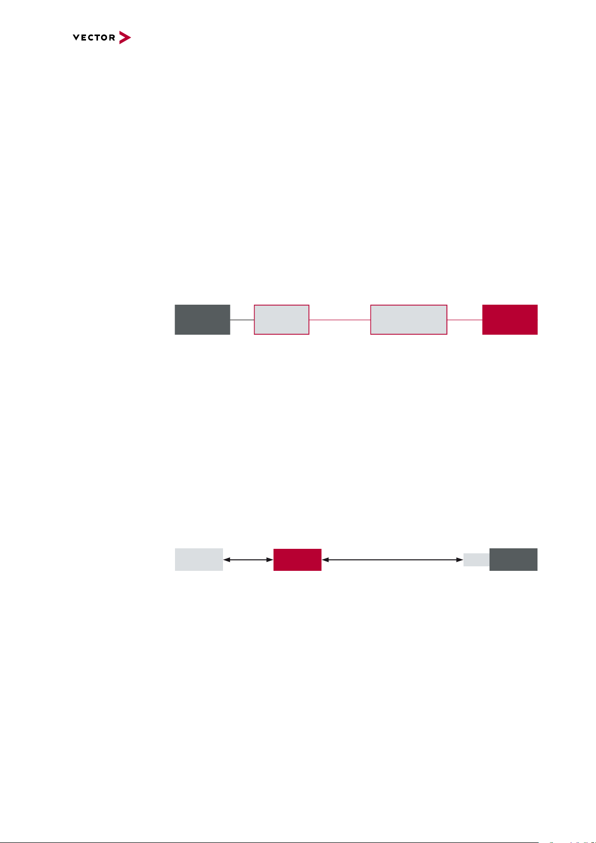
9.3 Ground and Shield Concept 434
9.3.1 Grounds and Shield inside VX Base Modules 434
9.3.2 Grounds inside a POD 435
9.3.3 Disconnecting an ECU from its Power Supply 436
9.3.3.1 #1: Normal Operation 437
9.3.3.2 #2: Disconnection 437
VX1000 Manual Version 4.3 12
Page 13

Contents
9.3.3.3 #3: Short 437
9.3.3.4 #4: Current in VX Base Module 438
9.3.3.5 #5: Current in POD Housing 438
9.3.3.6 #6: Current through POD Housing 439
9.3.3.7 Conclusion 439
9.4 Environmental Aspects 440
9.5 Cabling 441
VX1000 Manual Version 4.3 13
Page 14

1 Introduction
In this chapter you find the following information:
1.1 About this User Manual 15
1.1.1 Warranty 16
1.1.2 Registered Trademarks 16
1.2 Important Notes 17
1.2.1 Safety Instructions and Hazard Warnings 17
1.2.2 Disclaimer 18
VX1000 Manual Version 4.3 14
Page 15
1.1 About this User Manual
1.1 About this User Manual
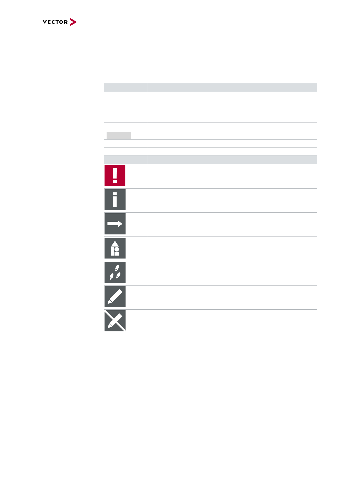
Conventions In the two following charts you will find the conventions used in the user manual
regarding utilized spellings and symbols.
Style Utilization
bold Blocks, surface elements, window- and dialog names of the soft-
ware. Accentuation of warnings and advices.
[OK]
File|Save
Source Code
Hyperlink Hyperlinks and references.
<CTRL>+<S> Notation for shortcuts.
Symbol Utilization
File name and source code.
This symbol calls your attention to warnings.
Push buttons in brackets
Notation for menus and menu entries
Here you can obtain supplemental information.
Here you can find additional information.
Here is an example that has been prepared for you.
Step-by-step instructions provide assistance at these points.
Instructions on editing files are found at these points.
This symbol warns you not to edit the specified file.
VX1000 Manual Version 4.3 15
Page 16

1.1.1 Warranty
1.1 About this User Manual
Restriction
of warranty
We reserve the right to change the contents of the documentation and the software
without notice. Vector Informatik GmbH assumes no liability for correct contents or
damages which are resulted from the usage of the documentation. We are grateful for
references to mistakes or for suggestions for improvement to be able to offer you
even more efficient products in the future.
1.1.2 Registered Trademarks
Registered
trademarks
All trademarks mentioned in this documentation and if necessary third party
registered are absolutely subject to the conditions of each valid label right and the
rights of particular registered proprietor. All trademarks, trade names or company
names are or can be trademarks or registered trademarks of their particular proprietors. All rights which are not expressly allowed are reserved. If an explicit label of
trademarks, which are used in this documentation, fails, should not mean that a name
is free of third party rights.
► Windows, Windows 7, Windows 8.1, Windows 10
are trademarks of the Microsoft Corporation.
VX1000 Manual Version 4.3 16
Page 17

1.2 Important Notes
1.2.1 Safety Instructions and Hazard Warnings
Caution!
In order to avoid personal injuries and damage to property, you have to read and
understand the following safety instructions and hazard warnings prior to installation and use of this hardware. Keep this documentation (manual) always near the
hardware.
1.2.1.1 Proper Use and Intended Purpose
Caution!
The hardware is designed for analyzing, controlling and otherwise influencing control systems and electronic control units. This includes bus systems like CAN,
FlexRay, Ethernet and/or BroadR-Reach.
1.2 Important Notes
The hardware may only be operated (i) according to the instructions and descriptions of this manual; (ii) with the electric power supply designed for the hardware,
e.g. USB-powered power supply; and (iii) with accessories manufactured or
approved by Vector.
The hardware is exclusively designed for use by skilled personnel as its operation
may result in serious personal injuries and damage to property. Therefore, only
those persons may operate the hardware who (i) have understood the possible
effects of the actions which may be caused by the hardware; (ii) are specifically
trained in the handling with the hardware, bus systems and the system intended to
be influenced; and (iii) have sufficient experience in using the hardware safely.
The knowledge necessary for the operation of the hardware can be acquired in
work-shops and internal or external seminars offered by Vector. Additional and
hardware specific information, such as „Known Issues“, are available in the „Vector
KnowledgeBase“on Vector´s website at www.vector.com. Please consult the
„Vector KnowledgeBase“for updated information prior to the operation of the hardware.
VX1000 Manual Version 4.3 17
Page 18

1.2.1.2 Hazards
1.2 Important Notes
Caution!
The hardware may control and/or otherwise influence the behavior of control systems and electronic control units. Serious hazards for life, body and property may
arise, in particular, without limitation, by interventions in safety relevant systems
(e.g. by deactivating or otherwise manipulating the engine management, steering,
airbag and/or braking system) and/or if the hardware is operated in public areas
(e.g. public traffic, airspace). Therefore, you must always ensure that the hardware
is used in a safe manner. This includes, inter alia, the ability to put the system in
which the hardware is used into a safe state at any time (e.g. by „emergency shutdown“), in particular, without limitation, in the event of errors or hazards.
Comply with all safety standards and public regulations which are relevant for the
operation of the system. Before you operate the system in public areas, it should
be tested on a site which is not accessible to the public and specifically prepared
for performing test drives in order to reduce hazards.
1.2.2 Disclaimer
Caution!
Claims based on defects and liability claims against Vector are excluded to the
extent damages or errors are caused by improper use of the hardware or use not
according to its intended purpose. The same applies to damages or errors arising
from insufficient training or lack of experience of personnel using the hardware.
VX1000 Manual Version 4.3 18
Page 19

2 VX1000 System Overview
In this chapter you find the following information:
2.1 Overview 20
2.2 VX1000 System Components 21
2.3 Supported Microcontrollers 22
2.4 Features 23
2.5 VX1000 Application Driver and VX1000If 24
VX1000 Manual Version 4.3 19
Page 20
2.1 Overview
Target µC POD Base Module
MC Tool
e. g. CANape
HSSL/Serial Cable XCP on
Ethernet
VX0312
CANape
BroadR-ReachUSB 2.0
ECU
XPOD
2.1 Overview
At a glance The VX1000 System is a scalable solution with top performance for your mea-
surement and calibration tasks. It can be used in the vehicle – both in the interior and
in the engine compartment – on test benches and in the laboratory.Especially when
developing ADAS ECUs, this allows you to control raw data captured by high-resolution radar sensors in combination with XCP data, e.g. object/tracking lists.
The system forms the interface between the ECU and a measurement and calibration
tool such as CANape.For high data throughput with minimal impact on ECU run-time,
data is accessed over the microcontroller-specific data trace and debug ports.
The VX1000 Base Module is connected to the PC over XCP on Ethernet, an OEMindependent ASAM standard (www.asam.net) that is widely used in the automotive
industry. The VX1000 measurement hardware is connected to the ECU via a POD
(Plug-On device).Depending on the available microcontroller interface, either the data
trace or a copying method can be used to acquire measurement data.
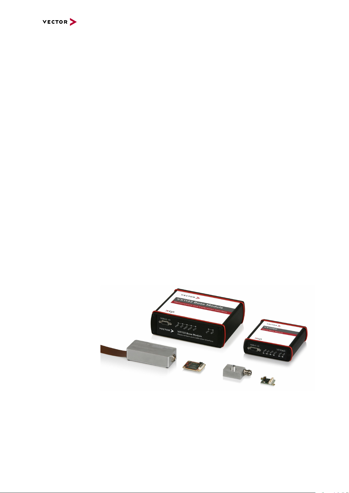
Figure 1: Modular concept
Modular concept The modular concept of the VX1000 System allows connecting to different micro-
controllers and consists of the following components:
► VX1000 Base Modules
► VX1300 Cables (HSSL/Serial Cable)
► VX1400/VX1500 Plug-On Devices (POD)
To support longer distances between the VX1000 Base Module and the target ECU,
e.g. under the hood in a car, the Base Module is connected to the ECU via a POD and
a cable that is available in different lengths.PODs and cables are designed to withstand rough automotive environmental conditions.
XPOD With the XPOD, the VX1000 System also offers a standalone measurement and cal-
ibration interface without the need of a VX1000 Base Module.
Figure 2: Example with XPOD
Advantages Advantages of the VX1000 System are:
► Powerful measurement and calibration access to internal ECU data with max-
imum transmission rates
► Very small POD to connect to the ECU debug interface
► Easy and quick integration into the ECU software
► No impact on ECU run-time with data trace measurement method
► Interface to numerous development tools by third-party suppliers via the stand-
ardized ASAM protocol XCP on Ethernet
► Special functions for engine controllers such as Calibration Wake-Up and Cal-
ibration RAM Supply
VX1000 Manual Version 4.3 20
Page 21
2.2 VX1000 System Components
Base Modules ► VX1060 Serial Base Module (page 55)
► VX1132 Base Module (page 71)
► VX1134 Base Module (page 110)
► VX1135 Base Module (page 128)
► VX1161 Multi Base Module (page 175)
2.2 VX1000 System Components
Plug-On Devices
(PODs)
Cables ► VX1311 Serial2 Cables for VX1544 Serial PODs (page 418)
Adapters ► VX19xx Target connection adapters (page 414)
Infrastructure
Hardware
XPOD ► VX1621A XPOD (page 365)
► VX1451 HSSL POD (RTP/DMM, Nexus AUX) (page 288)
► VX1452 HSSL POD (Aurora) (page 298)
► VX1453 HSSL POD (Aurora) (page 303)
► VX1461B HSSL POD PCIe (page 316)
► VX1463.01 HSSL POD AUR+1xRIF (page 321)
► VX1543A Serial POD (DAP, JTAG) (page 330)
► VX1544A/B Serial POD (DAP/DAP2, JTAG, HSCT, Zipwire) (page 344)
► VX134x Serial Cables and Cable Pigtails for VX154x Serial PODs (page 418)
► VX136x CAN Cables for Base Modules (page 410)
► VX137x HSSL Cables and Cable Pigtails for VX145x HSSL PODs (page 414)
► VX1381 HSSL2 Cables and Cable Pigtails for VX1453 HSSL PODs
► VX0312 Ethernet/CAN Interface
Figure 3: VX1000 Familyexamples
VX1000 Manual Version 4.3 21
Page 22

2.3 Supported Microcontrollers
This section contains a list of all currently supported microcontroller families. Please
contact Vector VX support (VXsupport@vector.com) for further information on supported microcontrollers and implemented features.
2.3 Supported Microcontrollers
Supported
Microcontroller
Infineon
TriCore TC1xxx (ED) DAP - DAP
TriCore AURIX TC2xx (ED) DAP2/HSCT Aurora DAP2
TriCore AURIX TC3xx (ED) DAP2/HSCT Aurora XC2000 DAP - -
NXP/ST
PowerPC xPC5xxx JTAG Class 2+/ Zipwire Aurora PowerPC MPC57xx - Aurora -
Renesas
RH850 JTAG Class 2+ Aurora V850E2 JTAG Class 2+ - -
Texas Instruments
TMSx70 - RTP/DMM -
VX154x
Serial PODs
VX145x
HSSL PODs
VX1621A
XPOD
VX1000 Manual Version 4.3 22
Page 23

2.4 Features
2.4 Features
Overview ► Very high measurement data throughput of more than 100 MByte/s for XCP data
and radar raw data with data trace measurement method and up to 3 MByte/s with
the copying method
► Measurement of fast signal cycles (>10 μs for data trace, 40 μs for copying
method)
► Measurement configurations with up to 100,000 signals can be processed
► Precise generation of DAQ time stamps in the ECU
► ECU cold start measurement (First Loop DAQ)
► Calibration of ECU parameters without address range limitations
► Calibration memory page switching
► Automatic overlays when calibrating parameters in flash memory
► Stimulation or bypassing with short latency times
► 100Mbps/1Gbps/10Gbps Ethernet connection to the PC
► Galvanically isolated power supply with wide input voltage range
► POD power supply via the VX1000 Base Module
► Optional: Flash programming, even for “brain-dead” ECUs
► Optional: FlexRay and CAN channels via XL Driver Library for CANape/CANa-
lyzer/CANoe and custom applications
► PC tools for easy configuration and for software updates
► Target debugging over XCP
VX1000 Manual Version 4.3 23
Page 24
2.5 VX1000 Application Driver and VX1000If
2.5 VX1000 Application Driver and VX1000If
VX1000 Measurement and Calibration access to the ECU requires not only the appropriate VX1000 hardware but also the target-specific VX1000 Application Driver (in
short: VX1000 AppDriver) which must be integrated into the ECU software.
The VX1000 AppDriver has been developed for test and development purposes but
not for use in production software. However, the VX1000 AppDriver is always used in
conjunction with the module VX1000If which encapsulates access from the application to the VX1000 AppDriver.
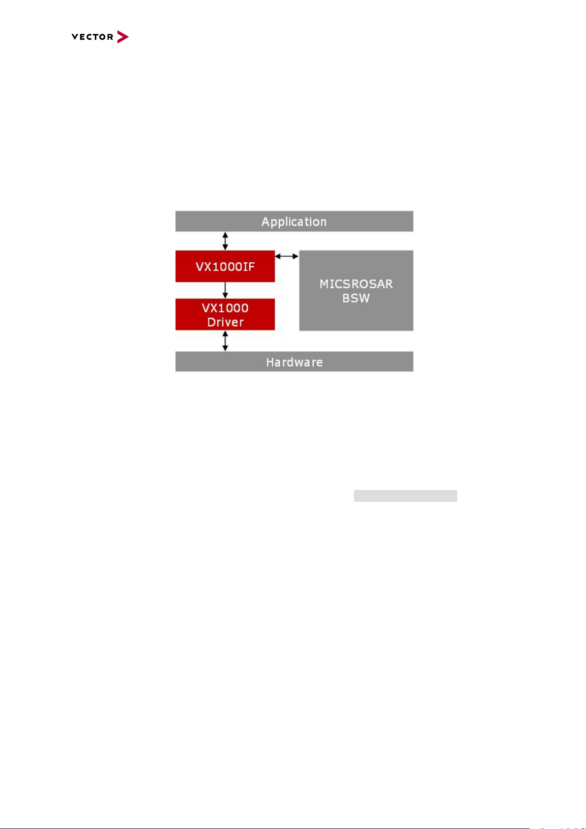
Figure 4: Application components
VX1000If provides an API through which, during runtime, the VX1000 AppDriver can
be activated for test and development purposes. Through this API the VX1000
AppDriver can also be put into a deactivated state in which it can potentially remain in
production software. Vector can only grant permission to use VX1000If and a thereover deactivated VX1000 AppDriver in production software, if VX1000If is delivered
through a MICROSAR SIP.
The VX1000 AppDriver is delivered through VXsupport@vector.com free of charge.
This delivery also contains a version of VX1000If and the technical reference required
for a complete and safe integration into the ECU software. This enables an integration
for test and development purposes, or an early prototype integration with exchanging
VX1000If later. Both the VX1000 AppDriver and VX1000If delivered this way, are subject to the attached terms and conditions which must be accepted on a per-project
base. These terms and conditions do not grant permission for usage in production
ECUs.
By means of a MICROSAR SIP, only VX1000If is delivered. Depending on the delivery, clearance for the usage in safety-critical ECUs up to ASIL-D can be granted. For
safe usage in a production ECU, the VX1000If version delivered through the
MICROSAR SIP must be used, including its technical specification.
Regarding VX1000If, usually there is no difference between the source code and technical reference of the MICROSAR SIP, or the version that is part of the VX1000
AppDriver. So, the effort for exchanging this component is usually very low. However,
care must be taken to diligently examine potential differences.
VX1000 Manual Version 4.3 24
Page 25

3 VXtools
In this chapter you find the following information:
3.1 VXupdate 26
3.1.1 General Information 26
3.1.2 Menu Bar 26
3.1.3 Toolbar 28
3.1.4 VX Device List 29
3.1.5 VX Configuration Selector 30
3.1.6 Image List 31
3.1.7 Flash Update 31
3.1.8 Status Bar 32
3.2 VXconfig 33
3.2.1 General Information 33
3.2.2 Menu Bar 34
3.2.3 Toolbar 37
3.2.4 Device List 38
3.2.5 Status Bar 39
3.3 VXconsole 40
3.3.1 General Information 40
3.3.2 Toolbar 41
3.3.3 LEDs 42
3.3.4 Message Window 42
3.3.5 Command Bar 42
3.3.6 Status Bar 43
3.4 HowTo 44
3.4.1 VXtools Setup 44
3.4.2 VX Device First Steps 45
3.4.3 VX device IP Address Configuration 46
3.4.4 FPGA and Firmware Update 49
3.4.5 Write VXparameter File to VX device 50
VX1000 Manual Version 4.3 25
Page 26
3.1 VXupdate
3.1 VXupdate
3.1.1 General Information
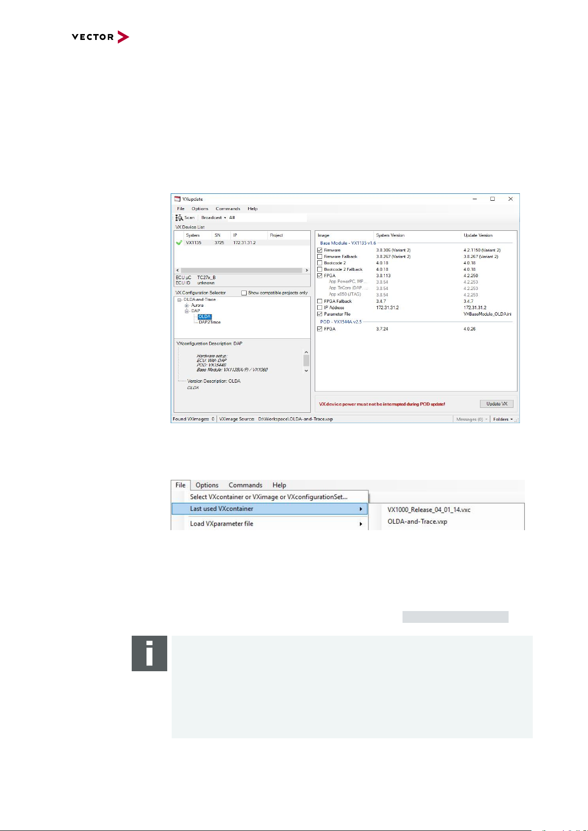
VXupdate VXupdate is the tool for updating VX1000 Systems by flashing VXimage files and
VXparameter files. It can be found in Start | Programs | Vector VXtools | VXup-
date after installation.
3.1.2 Menu Bar
File menu
► Select VXcontainer or VXimage or VXconfigurationSet…
This dialog allows selecting an individual .vxi VXimage, a .vxc VXcontainer or a
.vxp VXconfigurationSet. The VXimages and the parameter sets, which are
found and apply to the selected VX device, will be displayed in the Image List
view. If a VXconfigurationSet is selected the available VXconfigurations will be
listed in the VX Configuration Selector (see section VXconfiguration Selector).
Note
File types for the VX1000 System are:
.vxp VXconfigurationSet containing one or more VXconfigurations consisting of
VXimages and VXparameter files - can also be used to modify the IPaddress of a
VX device.
.vxc VXcontainer with a set of VXimage files for the VX1000 System.
.vxi VXimage file for the VX1000 System containing an FPGA or Firmware image
for a Base Module or a POD.
VX1000 Manual Version 4.3 26
Page 27
Options menu
Commands menu
3.1 VXupdate
► Last used VXcontainer
Lists already used VXcontainers or VXconfigurationSets. The user can select and
load one of them.
► Load VXparameter file
Loads a VXparameter set into the selected VX device.
► Exit
Closes VXupdate.
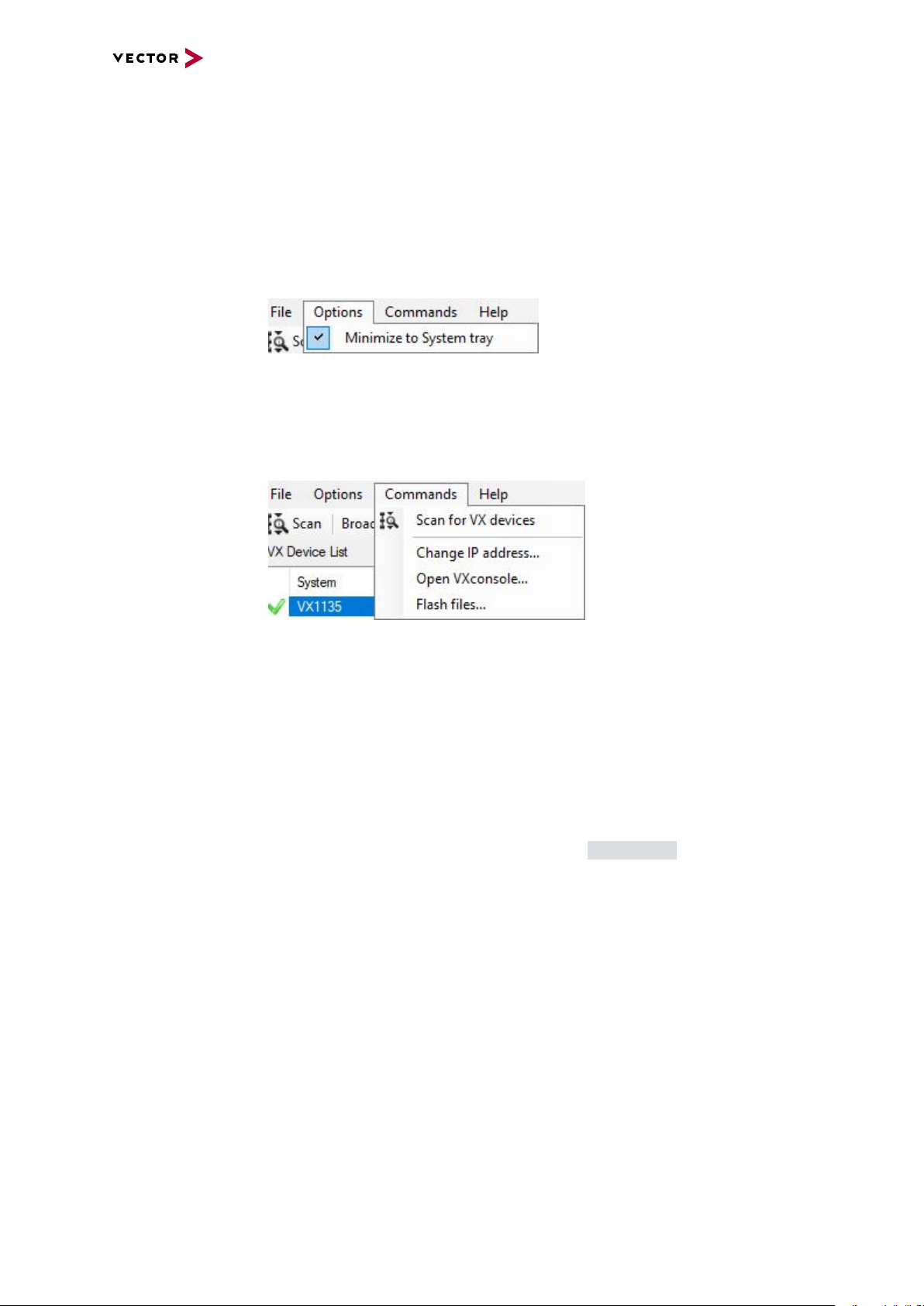
► Minimize to System tray
If this option is enabled, an icon will be added to the System tray.
When VXupdate is minimized, it will be removed from the Taskbar and can be
restored via the System tray icon.
► Scan for VX devices
Scans the network for VX devices. Found devices are shown in the Device List
view.
► Change IP address…
Changes the IP address of the selected VX device.
► Open VXconsole…
Opens VXconsole to display VX1000 System debug messages of the selected VX
device. This information is helpful for Vector support requests.
► Flash files…
Starts the flash update process (see section Flash Update)
VX1000 Manual Version 4.3 27
Page 28
Help menu
3.1 VXupdate
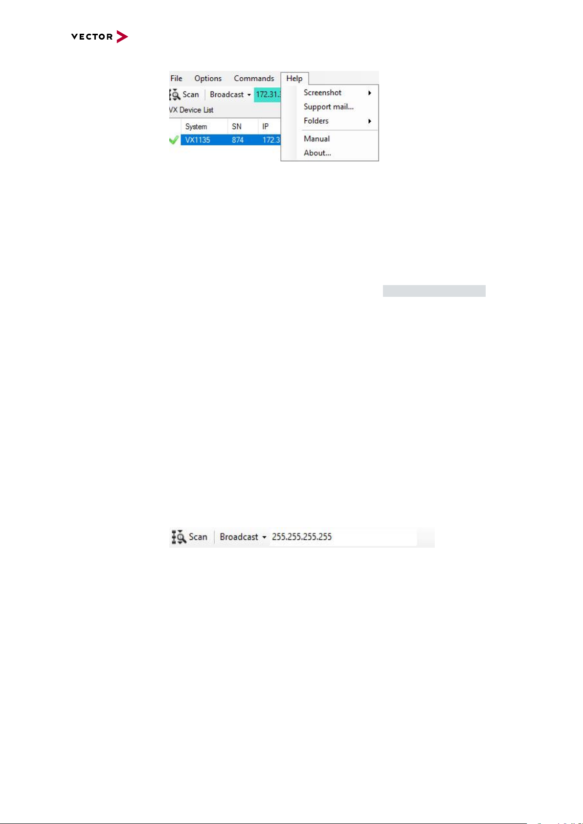
► Screenshot | Complete Desktop
Takes a screenshot of the whole Desktop and shows the location of the created
png file.
► Screenshot | VXupdate
Takes a screenshot of the VXupdate window and shows the location of the created png file.
► Support mail…
Creates a debug information file and opens a new E-Mail window in your default EMail client addressed to the Vector VX support (VXsupport@vector.com). Please
also include an issue description in the message body.
► Folders | User Data
Opens the Windows Explorer with the VXupdate User Data folder.
► Folders | Program Data
Opens the Windows Explorer with the VXupdate program folder.
► Manual | Manuals
Displays the installed VX1000 System Manuals and also offers a dialog to download further manuals.
► Manual | Application Notes
Displays the installed VX1000 Application Notes and also offers a dialog to download further VX1000 Application Notes.
► About…
Shows details of the VXupdate version.
3.1.3 Toolbar
Toolbar
► Scan
Scans the network for VX devices. Found devices are shown in the Device List
view.
► Broadcast
Sets the broadcast address for VX device scans. This parameter limits the scan to
a subnet (e.g. to a single network adapter) or covers all network adapters when a
value of 255.255.255.255 is used. Reasonable values can be found in the dropdown menu. If only one specific device should be found, its IP address can be
entered.
VX1000 Manual Version 4.3 28
Page 29
3.1.4 VX Device List
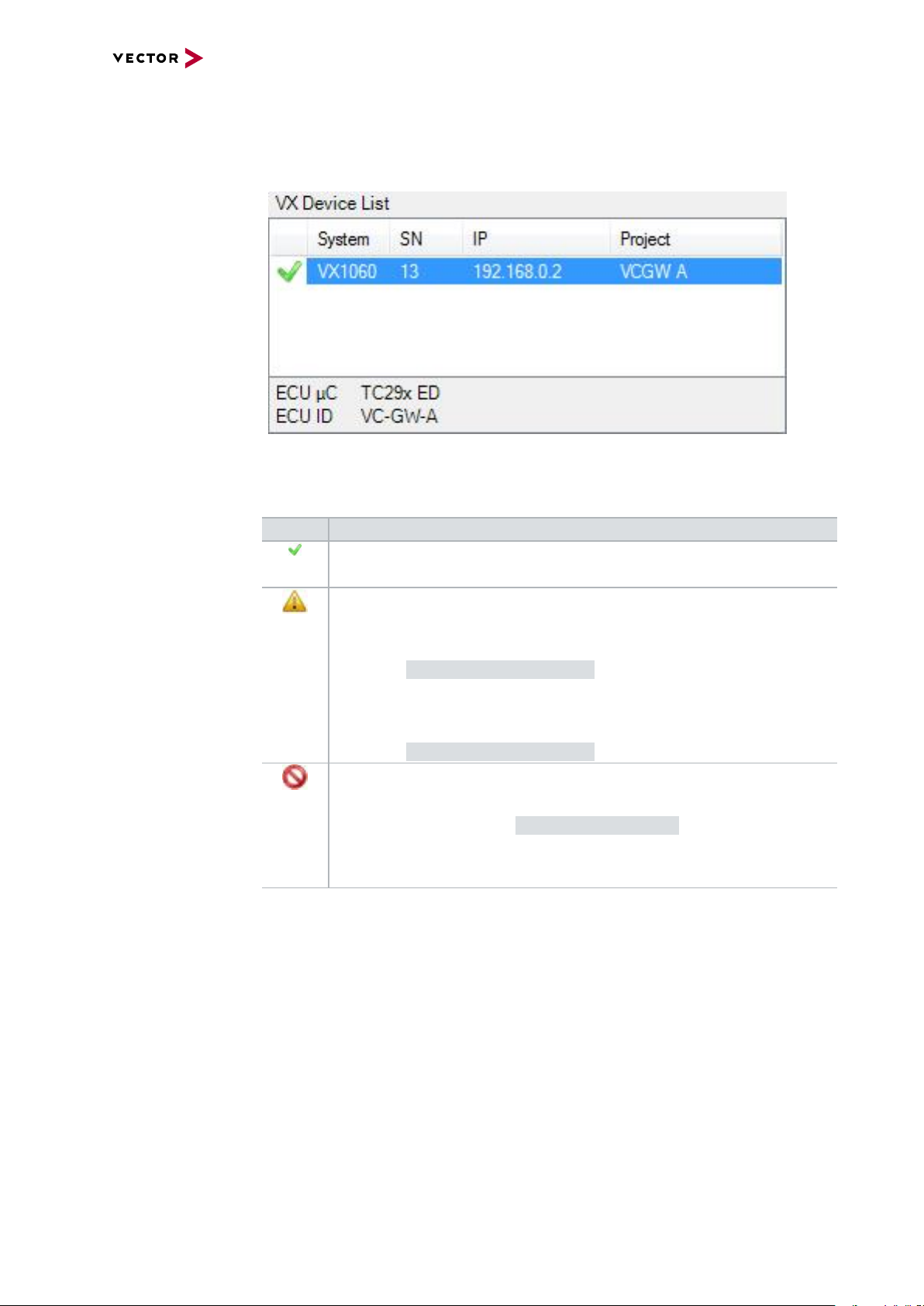
General information The Device List view displays all found VX devices in the network:
Device Status ► Status
The following device states are possible, after a scan has been executed:
3.1 VXupdate
Status Description / Possible problems
Device Info ► System
Displays the type of the found VX device.
► SN
Displays the serial number of the found VX device.
► IP
Displays the IP address of the found VX device.
► Project
Displays the Project ID of the POD connected to the VX device.
► VX device in normal operation.
► VX device contains valid VXimages for all of its hardware components.
► VX device contains an incompatible or outdated Firmware or FPGA
Image for at least one of its hardware components.
► Update the FPGA and Firmware Images (see section
FPGA and Firmware Update).
► VX1000 Fallback Firmware is active.
► Update the FPGA and Firmware Images (see section
FPGA and Firmware Update).
► VX device has invalid network settings.
► Correct the network settings of the VX1000 System (see
section VX1000 System IP Configuration).
► XCP slave is already in use by another XCP master (Measurement
tool).
ECU Info ► ECU µC
Displays the detected microcontroller type of the ECU connected to the selected
VX device.
VX1000 Manual Version 4.3 29
Page 30
► ECU ID
Displays the ECU-ID string defined in the VX1000 AppDriver of the ECU connected to the selected VX device.
3.1.5 VX Configuration Selector
3.1 VXupdate
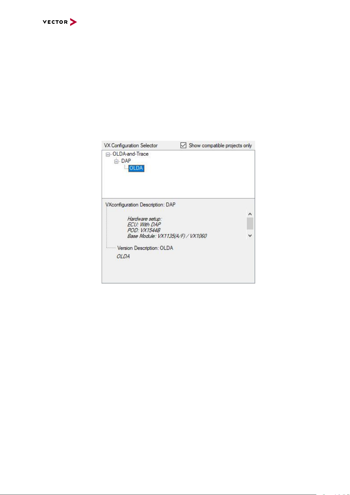
Configuration
Selector
When a VXconfigurationSet (.vxp) is loaded – via the File menu or via drag and drop –
the available configurations and their descriptions are shown in this view. By clicking
on one of the configuration sets the corresponding images and parameters are loaded
into the Image List view (update version column) and are available for flash programming into the VX device.
VX1000 Manual Version 4.3 30
Page 31

3.1 VXupdate
3.1.6 Image List
General information The Image List view displays the VXimages of the selected VX device which can be
selected and flashed.
List view ► Image
This column shows the compatible images and parameters of the loaded VXconfigurationSet, VXcontainer or VXimage for the selected VXdevice sorted by Base
Module and POD. Also the Base Module and POD type with hardware revision are
shown.
► System Version
This column shows the current VXimage version of the selected VX device.
► Update Version
This column shows the version of the VXimage file available for update.
3.1.7 Flash Update
Flash
The [Update VX] button starts the update for the selected VX device, applying all
selected images and parameters.
Caution!
The power supply of the VX device must not be interrupted during a POD update
procedure. The POD cannot recover from a failed update procedure.
VX1000 Manual Version 4.3 31
Page 32

3.1.8 Status Bar
Status bar
3.1 VXupdate
► Found VXimages
The number of VXimage files (*.vxi / *.hex / *.mem) inside a .vxc VXcontainer or
a directory containing VXimage files.
► VXimage Source
Storage location of the found VXimage files.
► Messages
VXupdate status messages will be grouped and available through the Messages
drop-down field.
► Folders | User Data
Opens the Windows Explorer with the VXupdate User Data folder.
► Folders | Program Data
Opens the Windows Explorer with the VXupdate program folder.
VX1000 Manual Version 4.3 32
Page 33

3.2 VXconfig
3.2.1 General Information
Configuration tool VXconfig is the configuration tool for the VX1000 System.
This tool provides access to all VXparameters which control the behavior of the VX
device. It also performs Firmware and FPGA updates using VXupdate.
VXconfig can be found in Start | Programs | Vector VXtools | VXconfig after instal-
lation.
3.2 VXconfig
Note
The parameters shown in VXconfig are a working copy of the parameters of the
selected VX device. These parameters can be edited in VXconfig without immediately affecting the VX device. If the parameters shall be written into the VX
device the commands Write configuration to VX1000 Base Module or Write
configuration to POD have to be used.
Importing VXparameters or POD parameters also just loads the parameters into
VXconfig and does not write the parameters into the VX device immediately.
VX1000 Manual Version 4.3 33
Page 34

3.2.2 Menu Bar
File menu
3.2 VXconfig
► New virtual VX device…
Inserts a new virtual VX device into the device list, either by using VXparameter
defaults or by importing VXparameters from a VXparameter file.
► Remove virtual VX device from Device List
The selected virtual device is deleted.
► Import VXparams…
Imports VXparameters from a VXparameter file into the selected VX device.
► Export VXparams…
Saves the current configuration of the selected VX device into a VXparameter file.
► Exit
Closes VXconfig.
Options menu
► Minimize to System tray
Enables an icon for VXconfig in the System tray. When VXconfig is minimized, it
will be removed from the Taskbar and can be restored via the System tray icon.
► Measurement tool
Selects the Measurement tool that will be taken into account for the plausibility
check.
► Plausibility check window
Hides or shows the plausibility check results. Selects the position of the plausibility check window.
VX1000 Manual Version 4.3 34
Page 35

Commands menu
3.2 VXconfig
► Scan for VX devices
Scans the network for VX devices. Found devices are shown in the Device List
view.
► Reboot VX device
Restarts the selected VX device.
► VX device info…
Shows details of the selected VX device.
► Identify VX device
Flashes the state LED of the VX device for 3 seconds. This feature can be used
for visual identification of a VX1000 Base Module.
► Refresh VX device status
Refreshes the status of the VX device (Scan, TCP, XCP, POD and ECU and
executes the Identify VX device command.
► Read configuration
Reads the current configuration from the POD of the selected VX device into
VXconfig.
► Write configuration
Writes the current configuration from VXconfig into the POD of the selected VX
device. The device will be restarted afterwards.
► Update VX device Firmware...
Opens VXupdate so that the Firmware images of the selected VX device can be
updated.
► Change IP address…
Changes the IP address of the selected VX device
► Force IP address…
Sets the IP address of a VX device even if it cannot be found by a scan e.g. due to
a Firewall problem. The VX device must be specified by Base Module type, Serial
Number, and Config XCP port.
VX1000 Manual Version 4.3 35
Page 36

Help menu
3.2 VXconfig
► Open VXconsole …
Opens VXconsole to display VX1000 System debug messages of the selected VX
device. This information is helpful for Vector support requests.
► Contents
Opens the help file.
► Screenshot | Complete Desktop
Takes a screenshot of the whole Desktop and shows the location of the created
png file.
► Screenshot | VXconfig
Takes a screenshot of the VXconfig window and shows the location of the created
png file.
► Support mail…
Creates a debug information file and opens a new E-Mail window in your default EMail client addressed to the Vector VX support (VXsupport@vector.com). Please
also include an issue description in the message body.
► Folders | User Data
Opens the Windows Explorer with the VXconfig User Data folder.
► Folders | Program Data
Opens the Windows Explorer with the VXconfig program folder.
► Manual | Manuals
Displays the installed VX1000 System Manuals and also offers a dialog to download further manuals.
► Manual | Application Notes
Displays the installed VX1000 Application Notes and also offers a dialog to download further VX1000 Application Notes.
► About…
Shows details of the VXconfig version.
VX1000 Manual Version 4.3 36
Page 37

3.2.3 Toolbar
Toolbar
3.2 VXconfig
► Scan
Scans the network for VX devices. Found devices are shown in the Device
List view.
► Broadcast
Sets the broadcast address for VX device scans. This parameter limits the scan to
a subnet (e.g. to a single network adapter) or covers all network adapters when a
value of 255.255.255.255 is used. Reasonable values can be found in the dropdown menu. If only one specific device should be found, its IP address can be
entered.
► Import VXparams
Opens an existing VXparameter file for editing.
► Export VXparams
Saves the current configuration as VXparameter file.
► Identify VX device
Flashes the state LED of the VX device for 3 seconds. This feature can be
used for visual identification of a VX1000 Base Module.
► Reboot VX device
Restarts the selected VX device.
► Read from VX device
Reads the configuration from the selected VX1000 Base Module into VXcon-
fig.
► Write to VX device
Writes the current configuration from VXconfig to the selected VX1000 Base
Module. The device will be restarted afterwards.
► Check settings
Displays the Plausibility Check window below or right to the VXconfig main
window.
VX1000 Manual Version 4.3 37
Page 38

3.2.4 Device List
3.2 VXconfig
General
information
Device Status The following device states are possible and shown as a symbol on the left of the
VX1000 Base Module type:
Status Description / Possible problems
► VX device in normal operation.
► VX device contains valid VXimages for all of its hardware components.
► VX device contains an incompatible or outdated FPGA or Firmware
Image for at least one of its hardware components.
► Update the FPGA and Firmware Images (see section
FPGA and Firmware Update).
The Device List view displays all detected VX
devices in the network after a scan. The tree structure provides a grouped access to all available
VXparameters. Each top-level entry of the Device
List view contains a device status symbol followed by Base Module type, serial number and
network IP address. Tree entries marked in bold
font indicate modified VXparameters that have
not been saved or written to the VX device.
► VX1000 Fallback Firmware is active.
► Update the FPGA and Firmware Images (see section
FPGA and Firmware Update).
► VX device has invalid network settings.
► Correct the network settings of the VX1000 System (see
section VX device IP Address Configuration on page
46).
► XCP slave is already in use by another XCP master (Measurement
tool).
► Check the VX device Status.
► Base Module type
The Base Module type (e.g. VX1132) is printed next to the Device State symbol.
► Serial Number
The Serial Number of the VX1000 Base Module is shown next to the Base Module
type.
► IP address
The IP address of the VX1000 Base Module is shown after the Serial Number.
VX1000 Manual Version 4.3 38
Page 39

3.2.5 Status Bar
Status bar
3.2 VXconfig
► Command Status Information
The Status bar shows information about the currently or last executed command.
► Messages
VXconfig status messages will be grouped and available through the Messages
drop-down field.
► Folders | User Data
Opens the Windows Explorer with the VXconfig User Data folder.
► Folders | Program Data
Opens the Windows Explorer with the VXconfig program folder.
VX1000 Manual Version 4.3 39
Page 40

3.3 VXconsole
3.3 VXconsole
3.3.1 General Information
VXconsole VXconsole is a tool for displaying VX1000 System messages provided by the VX1000
Base Module via Telnet protocol. It can be found in both VXconfig and VXupdate
under Commands | Open VXconsole.
The VXconsole window consists of a toolbar, LEDs, message window, command bar
and status bar.
Note
The logged messages which were generated since the last restart of the VX1000
System are helpful information for Vector support requests.
VX1000 Manual Version 4.3 40
Page 41

3.3.2 Toolbar
Toolbar
3.3 VXconsole
► Open Log-File
Opens an existing log file for viewing.
► Save Log-File
Saves the current logged messages as text/log file.
► Send logged messages to Vector VX support
Copies the logged messages into a text file and opens an E-Mail window of
the default E-Mail client addressed to the Vector VX support (VXsupport@vector.com). Please also include an issue description in the message body
► Copy logged messages
Copies the logged messages to the clipboard.
► Insert clipboard into message window
Inserts content of the clipboard into the message window.
► Clear logged messages
Clears the message window.
► Insert marker
Inserts a text line marker showing the current time.
► Scan
Scans the network for VX devices to determine the IP address of a specific
VX device.
► Connect
Opens a Telnet connection to the VX device with the given IP address.
► Disconnect
Disconnects the Telnet connection with the VX device.
► Options
Provides options to control the behavior of VXconsole.
The tool can:
+ automatically connect to the VX device (last used IP address)
+ write the debug messages into a Log-File
+ automatically reconnect when the Telnet connection gets lost (e.g. during a VX
device restart)
+ keep the VXconsole window always on top
► About
Opens the details of the VXconsole version.
VX1000 Manual Version 4.3 41
Page 42

3.3.3 LEDs
Reference
The LED images below the toolbar mirror the state of the selected Base Module.
Please find the specific LED descriptions in the according section (see Base Modules on page 53).
3.3.4 Message Window
The Message window contains primarily the logged messages of the VX1000 System
in addition to Telnet status messages. Those messages are color-coded and have the
following meaning:
BLUE TEXT Telnet status messages or markers generated by VXconsole
BLACK TEXT Standard/normal messages of the VX1000 System
ORANGE TEXT Warning messages of the VX1000 System
RED TEXT Error/Critical messages of the VX1000System
Message Window
3.3 VXconsole
3.3.5 Command Bar
Command bar The Command bar allows sending of telnet command strings to the VX device. At the
moment, only the “replay” command is supported.
VX1000 Manual Version 4.3 42
Page 43

3.3.6 Status Bar
Status bar
3.3 VXconsole
► IP Address
IP address of the VXdevice to which the last connection (attempt) was made.
► Connection Status
Status of the current Telnet connection.
► Messages
VXconsole status messages will be grouped and available through the Messages
drop-down field.
► Folders | User Data
Opens the Windows Explorer with the VXconsole User Data folder.
► Folders | Program Data
Opens the Windows Explorer with the VXconsole program folder.
VX1000 Manual Version 4.3 43
Page 44

3.4 HowTo
3.4 HowTo
The following subsections contain step-by-step installation instructions and system
procedures when working with the VX1000 System.
3.4.1 VXtools Setup
3.4.1.1 Overview
General Information VXtoolsSetup_<version>.exe is the setup program for the Vector VXtools con-
taining
► VXupdate (Firmware and FPGA update tool for the VX1000 System)
► CANape VXplugin (CANape plugin to configure the VX1000 System)
► VXcontainer (container with a set of VXimage files for the VX1000 System)
► VXconfig (configuration tool for the VX1000 System)
► VXconsole (tool for displaying VX1000 System debug messages)
Reference
The latest version of the VXtoolsSetup is available in the Vector Download-Center.
3.4.1.2 Minimum Requirements
Hardware Ethernet (100 Mbps, 1 Gbps, 10 Gbps recommended)
Operating system Microsoft Windows 7
Microsoft Windows 8.1
Microsoft Windows 10
Library Microsoft .NET Framework 4.0
Note
Please note that Administrator rights are required for the installation procedure.
3.4.1.3 Installations Instructions
VXtoolsSetup The VXtools (VXconfig, VXconsole and VXupdate) can be installed by running the
VXtools installation wizard. Please run the VXtoolsSetup_<version>.exe and
follow the installation dialog.
VX1000 Manual Version 4.3 44
Page 45

3.4 HowTo
3.4.2 VX Device First Steps
VXconfig Establishing first contact with a VX device is easily done with VXconfig, which is part
of the VXtools package.
Step by Step Procedure
Please follow these steps:
1. Connect an Ethernet cable to the VX device.
2. Connect this cable directly to a PC or to a network switch.
3. Connect the power supply to the connector labeled with “Power”. The Power
LED should now be on.
4. Run VXconfig from the Start menu
(Start | Programs | Vector VXtools | VXconfig).
5. Check if the connected VX device was recognized by VXconfig. It should be listed in the Device List view. Furthermore, the VX device status should display
green symbols for Scan status, TCP status and XCP status.
Note
If the IP address of the VX device does not match the local subnet of the PC, it
must be adjusted for the VX device to be accessible.
VX1000 Manual Version 4.3 45
Page 46

3.4 HowTo
3.4.3 VX device IP Address Configuration
VXconfig The VX device IP configuration is easily done with VXconfig, which is part of the
VXtools package.
There are two ways to change an IP address. If the VX device was recognized by
VXconfig, it can be changed using the command Change IP Address. Otherwise
Force IP Address has to be used.
Caution!
An unused IP address, which matches your local subnet, has to be provided by
your network administrator.
3.4.3.1 Change IPAddress
Change IP address This procedure describes how to change the IP address of a VX device that was
found during a Scan with VXconfig.
Step by Step Procedure
Please follow these steps:
1. Ensure that the VX device is correctly installed, connected to the PC and running.
2. Run VXconfig from the Start menu
(Start | Programs | Vector VXtools | VXconfig).
3. Select the VX device whose IP address has to be changed in the Device List
view.
VX1000 Manual Version 4.3 46
Page 47

3.4 HowTo
4. Execute Commands | Change IP address… from the Menu bar to open the
IP address change dialog. Enter the new IP address provided by your network
administrator and press [OK].
5. If the newly entered IP address resides within a different subnet than the previous address, please press [Scan].
VX1000 Manual Version 4.3 47
Page 48

3.4.3.2 Force IP Address
This procedure describes how to change the IP address of a VX device that was not
found during a Scan with VXconfig.
Caution!
An unused IP address, which matches your local subnet, has to be provided by
your network administrator.
Step by Step Procedure
Please follow these steps:
1. Ensure that the VX device is correctly installed, connected to the PC and running.
2. Run VXconfig from the Start menu
(Start | Programs | Vector VXtools | VXconfig).
3. The VX device whose IP address has to be changed is not shown in the Device
List view.
4. Execute Commands | Force IP address… from the Menu bar to open the IP
address change dialog. Select the Base Module type and the serial number of
the unrecognized VX device, enter the new IP address provided by your network administrator and change the Config XCP port (default: 5556), if necessary. Press [OK] afterwards.
3.4 HowTo
VX1000 Manual Version 4.3 48
Page 49

3.4.4 FPGA and Firmware Update
FPGA and Firmware updates of the VX1000 Base Module and the VX1400/VX1500
Plug-On Devices are easily done with VXupdate.
Note
The FPGA Image of the POD cannot be updated, if the present version is equal to
the update version.
Step by Step Procedure
Please follow these steps:
1. Ensure that the VX device is connected to the PC and running.
2. Run VXupdate from the Start menu
(Start | Programs | Vector VXtools | VXupdate).
3. Go to menu File | Select VXcontainer and select the container with the Firm-
ware and FPGA files for update. Press [Open].
4. Select the VX device that is to be updated, e.g. VX1060 with serial number 13.
3.4 HowTo
5. Select the FPGA and Firmware Images that are to be updated. VXupdate will
automatically select all components for which an update is available.
6. Press [Flash] to start the update process.
VX1000 Manual Version 4.3 49
Page 50

3.4 HowTo
3.4.5 Write VXparameter File to VX device
The VX1000 Base Module can be easily configured with VXconfig or VXupdate by
loading a prepared VXparameter file into the VX1000 Base Module.
Note
VXupdate is recommended to download a valid VXparameter file without former
modification of the parameters. VXconfig has to be used if the VXparameter file
contains errors or if modifications have to be made before the parameters are downloaded into the VX device.
VXconfig procedure VXconfig allows importing a prepared VXparameter file, reviewing and changing the
VXparameter set, correction of invalid VXparameter values and downloading those
settings into an available VX1000 System.
Step by Step Procedure
Please follow these steps:
1. Ensure that the VX device is connected to the PC and running.
2. Run VXconfig from the Start menu
(Start | Programs | Vector VXtools | VXconfig).
3. Select the VX device in the Device List view that shall receive the VXparameter file and open the Base Module page by clicking on the Base Module tree
entry.
4. Press [Import VXparams file…] on the Base Module page or from the File
menu and select the prepared configuration file. To load the settings into VXconfig, press [Open] in the file selection window and confirm the import dialog with
[OK].
VX1000 Manual Version 4.3 50
Page 51

3.4 HowTo
5. To download the configuration into the VX device press [Write to VX]. The tool
performs a scan once the configuration is written.
VX1000 Manual Version 4.3 51
Page 52

3.4 HowTo
VXupdate procedure The VXupdate tool allows downloading of a prepared and valid VXparameter file into
an available VX device.
Step by Step Procedure
Please follow these steps:
1. Ensure that the VX device is connected to the PC and running.
2. Run VXupdate from the Start menu
(Start | Programs | Vector VXtools | VXupdate).
3. Select the VX device in the Device List view that shall receive the VXparameter file (e.g. VX1060 with serial number 13).
4. Go to File | Load VXparameter file | <<filename>> on the Menu bar and
select the prepared VXparameter file.
5. After the VXparameter file was downloaded into the VX device, press [OK] to
close the “Update Process” dialog, if necessary. The tool performs a Scan afterwards.
VX1000 Manual Version 4.3 52
Page 53

4 Base Modules
In this chapter you find the following information:
4.1 VX1060 Serial Base Module 55
4.1.1 Connectors 55
4.1.2 LEDs 57
4.1.3 Technical Data 61
4.2 VX1132 Base Modules 62
4.2.1 VX1132A 63
4.2.2 VX1132B 71
4.2.3 VX1132C 79
4.2.4 VX1132E 86
4.2.5 VX1132H 95
4.2.6 VX1132S 102
4.3 VX1134 Base Modules 110
4.3.1 VX1134B 110
4.3.2 VX1134C 119
4.4 VX1135 Base Modules 128
4.4.1 VX1135A 128
4.4.2 VX1135C 138
4.4.3 VX1135D 148
4.4.4 VX1135E 157
4.4.5 VX1135F 166
4.5 VX1161 Multi Base Module 175
4.5.1 General Information 175
4.5.2 VX1161.01A Base 176
4.5.3 VX1161.11 Power Supply 177
4.5.4 VX1161.22A Host Uplink 180
4.5.5 VX1161.22B Host Uplink 186
4.5.6 VX1161.31A Serial 192
4.5.7 VX1161.32B HSSL 196
4.5.8 VX1161.32C HSSL2 200
4.5.9 VX1161.41A 6xCAN 204
4.5.10 VX1161.41B 6xCAN 1xFR 208
4.5.11 VX1161.51A 2xTAP FPDLINK3 Ti954/Ti953 212
4.5.12 VX1161.51B 4xRX FPDLINK3 TI954/TI954 225
4.5.13 VX1161.51C 2xTAP GMSL2 MX9296A/MX9295A 233
4.5.14 VX1161.51D 4xRX GMSL2 MX9296 249
4.5.15 Inserting or Removing VX1161 Cards 260
4.5.16 Calculation and Scripting Language (CASL) 262
VX1000 Manual Version 4.3 53
Page 54

4.5.17 VXconfig for VX1161.51 275
VX1000 Manual Version 4.3 54
Page 55

4.1 VX1060 Serial Base Module
4.1.1 Connectors
Figure 5: VX1060 Serial Base Module front side
► DEBUG • IO
A VX199x Debugger Adapter may be attached to this connector. The VX199x
Debugger Adapters offer the possibility to connect a Debugger Hardware (like
from PLS or Lauterbach) to the VX1060 Base Module. This allows debugging of
the target device through the VX1060 hardware.
4.1 VX1060 Serial Base Module
Figure 6: VX1060 Serial Base Module backside
► PWR • SYNC
Power is provided through a 3-pin Binder connector (labeled with PWR • SYNC)
on the back side of the VX1060 Base Module. The power supply is protected
against reverse polarity and over-current.Vector offers different accessories for
supplying power with a mating 3-pin female Binder connector (type 711).
Hardware time synchronization allows the Measurement and Calibration tool to
synchronize the timestamps of different devices to a common time base with a precision of 1 µs.For synchronization of VX devices a two-wire connection (signals:
Sync, GND) between all devices is required. At each falling edge on the Sync line
the VX device generates a timestamp that is provided to the Measurement and Calibration tool via XCP.
Reference
Power supply cables and sync cables can be found in section Cables on page
402.
VX1000 Manual Version 4.3 55
Page 56

4.1 VX1060 Serial Base Module
Y
GGGGGGG
G
YYYYYYY
Y
YYY
Y
► ETH
The communication between a Measurement and Calibration tool like CANape
and the VX1000 System is realized by XCP over Ethernet. Therefore the VX1060
must be connected to a common PC network with a network cable (Cat 5 or better). As the Ethernet interface features Auto-MDI(X) a crossover cable or patch
cable can be used equivalently.
The following protocols are supported for measurement and calibration:
- XCP on TCP
- XCP on UDP
Ensure that no Firewall on the network or on the PC blocks the traffic of the
VX1000 System. The Ethernet connector contains two LEDs (100 and ACT). The
description of both indicators is given in the following two tables.
The LED indicators show a recurring sequence of colors and blink codes. The following block icons are used to describe this sequence:
= off
= yellowG= green
100
LED indicating the link speed.
Sequence Description
Link speed is 10 Mbit/s
Link speed is 100 Mbit/s
ACT
LED indicating the Ethernet activity status.
Sequence Description
Ethernet link is down
(see section VXconsole on page 40)
Ethernet link is up
Ethernet link is up and activity is detected
► POD (red or blue)
This connector is used to attach a VX154x Serial POD.
A blue connector isolation indicates, that the connector housing (and therefore the
shield of a connected cable) is capacitively coupled to the internal system ground
of the VX1060 Serial Base Module (starting with HW-Rev. 5.0).
A red connector isolation indicates, that the connector housing (and therefore the
shield of a connected cable) is directly connected to the internal system ground of
the VX1060 Serial Base Module (before HW-Rev. 5.0).
VX1000 Manual Version 4.3 56
Page 57

4.1 VX1060 Serial Base Module
R
RRRRRRR
R
GGGGGGG
G
GGG
G
R
RRRRRRR
R
GGGGGGG
G
4.1.2 LEDs
Overview On the front side, there are several LEDs that display the state of the Base Module,
the attached POD and the target ECU.
The following tables list all available LED sequences and describe the condition at
which they will be active.
The LED indicators show a recurring sequence of colors and blink codes. The following block icons are used to describe this sequence:
= off
PWR (Power) Sequence Description
= redG= green
Device is powered but Firmware not running.
The PWR LED will light up red at the beginning of the boot
sequence of the Base Module.
► Please contact Vector VX support if the PWR LED stays
red for more than 10 seconds. In this case a critical error
has occurred.
Firmware loaded successfully.
Response to ”Identify VX device command” (VXconfig)
Standby Mode is active.
A cyclical short red pulse on the PWR LED indicates that the
Base Module is in Standby Mode.
► Please contact the VX support if the Standby Mode is not
left even if the Ethernet Host link is up again for more than
10 seconds.
SYS (System) Sequence Description
Firmware not loaded.
Device is in update-only operating mode.
During the boot sequence of the Base Module, its system
components are initialized. If a component fails to initialize
properly, the SYS LED stays red.
► Please perform a FPGA and firmware update as
described in section FPGA and Firmware Update on page
49. If that condition persists after the update, please con-
tact Vector VX support.
Device is in normal operating mode
VX1000 Manual Version 4.3 57
Page 58

POD Sequence Description
RRRRRRR
R
GGGGGGG
G
GGGGRRR
R
RRRRRRR
R
RRR
R
Device is not in normal operating mode.
POD not detected.
After the Base Module boot sequence has been completed
successfully, the system searches for an attached POD. As
long as no POD is found, the POD LED will stay red.
► Please check if the cable between POD and Base Module
is undamaged.
► Please also check if all connectors are correctly locked
into their corresponding sockets.
POD in normal operating mode
POD detected but configuration incorrect
The POD was detected by the Base Module, but the target
interface configuration is incorrect.
► Please open VXconfig and adjust the POD settings
according to the target ECU configuration.
4.1 VX1060 Serial Base Module
ECU Sequence Description
POD not in normal operating mode
Target microcontroller not detected.
The POD was detected by the VX1000 Base Module and is
configured correctly, but the target ECU cannot be accessed.
► Please check if the POD is connected (via an appropriate
cable) to the target microcontroller.
► Please check if the target system is powered correctly
and operational.
► Please check if the target interface settings of the POD
match the ECU configuration.
For some targets, the target interface is disabled if the ECU
parameter structure is not found.
► Please check if the ECU parameter structure (gVX1000)
is present in the target RAM and that its address is cor-
rectly configured in VXconfig.
Inconsistent Measurement Data detected.
The target microcontroller is accessible and was configured
correctly to be accessed by the VX1000 System. The
VX1000 detected a situation where the consistency of the
measurement data cannot be guaranteed anymore. Therefore
the measurement process was stopped. All data processed
up to that event are valid and consistent.
This problem can either be caused by:
► Overload Situations
VX1000 Manual Version 4.3 58
Page 59

ECU Sequence Description
GGG
G
GGGGGGG
G
GGGGGGG
R
RRRRRRR
R
RRR
R
- Possible Solution: Increase target interface clock fre-
quency of the POD, if possible.
► Technical issues of either ECU or VX1000
- See the VXconsole log or the messages sent via XCP
to the XCP-Master (e.g. CANape) for details.
RAM synchronization in process
Target microcontroller detected and configuration correct
Target microcontroller detected but configuration incorrect
The target microcontroller is accessible but was not configured correctly to be accessed by the VX1000 System. This
means the settings made in VXconfig do not match the properties of the ECU Code Instrumentation.
► Please check if the ECU Parameter Structure address
set in VXconfig matches the address in the Linker MAP
file of the target ECU code.
► Please check if the byte order set in VXconfig matches
the byte order of the target ECU.
4.1 VX1060 Serial Base Module
ETH (Ethernet) Sequence Description
Ethernet link is down.
The Ethernet link between the VX device and the next active
network component (e.g. PC or switch) is down.
► Please verify that an appropriate Ethernet cable is prop-
erly connected to the Base Module.
► Please verify that all network components between the
Base Module and the PC are operational.
► Please verify if the Ethernet cable is not damaged.
Ethernet link up but no IP address assigned via DHCP
Ethernet link activity but no IP address assigned via DHCP .
The Ethernet link is up and the IP address has not yet been
assigned by a DHCP server. This might take a few seconds.
As soon as a valid IP address has been assigned, the ETH
LED color will change to green.
The System is not accessible unless a valid IP address is
configured.
Depending on the network configuration there are different
solutions:
1. Network with static IP address allocation
► Please set a valid IP address for the given network with
VXconfig as described in section VX device IP Address
Configuration on page 46. Please verify afterwards with
VXconfig that the DHCP Mode is set to “Off”.
2. Network with dynamic IP address allocation (assigned via
VX1000 Manual Version 4.3 59
Page 60

ETH (Ethernet) Sequence Description
GGGGGGG
G
GGG
G
RRR
R
GGGGGGG
G
GGG
G
GGGGRRR
R
DHCP server)
► Please consult the IT systems administrator if the ETH
LED color stays red.
Ethernet link is up (network configured)
Ethernet link activity (network configured).
The Base Module detected an active Ethernet connection
and is configured with a valid IP address either via the DHCP
server or the stored static IP address.
If there is no network connection with the Base Module possible, the following items should be verified:
► Please check if the configured IP address of the System
matches the subnet of the used network.
► Please check if the network traffic between the PC and
the System is not filtered (blocked) by any Firewall
present in the network.
4.1 VX1060 Serial Base Module
XCP Sequence Description
No XCP master connected to the device.
XCP connection to Config XCP slave (no ECU access).
A XCP master is connected to the Config XCP port/slave of
the Base Module. This port is reserved for the VXtools
(VXconfig and VXupdate) and cannot be used by the Measurement tool as access to the target is suppressed.
► Please verify that the measurement port configuration of
the Measurement tool (A2L) and the VX device are match-
ing. The settings of the VX device can be checked and
modified via VXconfig.
XCP connection to Fully-Featured or Limited XCP slave
DAQ measurement running
DAQ measurement running and DAQ overload detected
The ECU generated too much measurement data in a short
period of time which could not be processed by the System.
In that case the measurement process will continue but there
will be a data loss. All available data are valid and consistent.
► Please increase the target interface clock frequency of
the POD, if possible.
► Please reduce the amount of generated measurement
data by reducing the number of measurement signals in
the measurement configuration.
► Please reduce the amount of generated measurement
data by reducing the size of the data trace windows.
VX1000 Manual Version 4.3 60
Page 61

4.1.3 Technical Data
Dimensions (W/D/H) 106 x 115 x 32 mm
Weight 330 g
Power supply 5.5 VDC to 50 VDC (operating voltage)
Power consumption typ. 250 mA @ 12V (without POD)
Temperature range -40°C to +70°C
PC interface Ethernet 100 Mbit/s
XCP data rate up to 10 Mbyte/s DAQ data
Part number 22218
4.1 VX1060 Serial Base Module
7.5 VDC to 50 VDC (start-up voltage)
Standby: 70 mA @ 12 V
VX1000 Manual Version 4.3 61
Page 62

4.2 VX1132 Base Modules
Note
All VX1132 Base Modules are discontinued.
This means that the devices are still supported by the VXtools and also still get
updates with new features and bug fixes but the hardware is no longer sold. Successors are the VX1134 and VX1135 Base Modules and the VX1161 Multi Base
Module.
4.2 VX1132 Base Modules
VX1000 Manual Version 4.3 62
Page 63

4.2.1 VX1132A
4.2.1.1 Connectors
4.2 VX1132 Base Modules
Figure 7: VX1132A Base Module front side
► DEBUG • IO
A VX199x Debugger Adapter may be attached to this connector. The VX199x
Debugger Adapters offer the possibility to connect a Debugger Hardware (like
from PLS or Lauterbach) to the VX1000 Base Module. This allows debugging of
the target device through the VX1000 hardware.
Figure 8: VX1132A Base Module backside
► POD1 • HSSL
This connector is used to attach a VX14xx HSSL POD with VX137x HSSL Cable.
The connector housing (and therefore the shield of a connected cable) is directly
connected to the internal system ground of the VX1132A Base Module.
► POD2 • SERIAL
This connector is used to attach a VX154x Serial POD. The connector housing
(and therefore the shield of a connected cable) is directly connected to the internal
system ground of the VX1132A Base Module.
► HOST ETH
The communication between a Measurement and Calibration tool like CANape
and the VX1000 System is realized by XCP over Ethernet. Therefore the
VX1132A must be connected to a common PC network with a network cable (Cat
5 or better). As the Ethernet interface features Auto-MDI(X) a crossover cable or
patch cable can be used equivalently.
The following protocols are supported for measurement and calibration:
- XCP on TCP
- XCP on UDP
VX1000 Manual Version 4.3 63
Page 64

4.2 VX1132 Base Modules
Y
GGGGGGG
G
YYYYYYY
Y
GGG
G
Ensure that no Firewall on the network or on the PC blocks the traffic of the
VX1000 System. The Ethernet connector contains two LEDs (100 and ACT). The
description of both indicators is given in the following two tables.
The LED indicators show a recurring sequence of colors and blink codes. The following block icons are used to describe this sequence:
= off
= yellowG= green
LNK
LED indicating the link speed.
Sequence Description
Ethernet link is down
100 Mbit/s Ethernet link is up
1000 Mbit/s Ethernet link is up
ACT
LED indicating the Ethernet activity status.
Sequence Description
No Ethernet activity
Ethernet activity
► SYNC
Hardware time synchronization allows the Measurement and Calibration tool to
synchronize the timestamps of different devices to a common time base with a precision of 1 µs.For synchronization of VX devices a two-wire connection (signals:
Sync, GND) between all devices is required. At each falling edge on the Sync line
the VX device generates a timestamp that is provided to the Measurement and Calibration tool via XCP.
Reference
Power supply cables and Sync cables can be found in section Cables on page
402.
► PWR
Power is provided through a 2-pin ODU Mini-Snap male connector (labeled with
PWR) on the back side of the VX1132A. The power supply is protected against
reverse polarity and over-current. All power domains (input power supply,
POD/ECU, FlexRay, CAN) are galvanically isolated to avoid stray electric currents. Vector offers different accessories for supplying power with a mating 2-pin
ODU Mini-Snap female connector.
VX1000 Manual Version 4.3 64
Page 65

4.2 VX1132 Base Modules
5
4
3
2
1
6
789
1
2
3
► FLEXRAY
The VX1132A offers a FlexRay receiver for one channel A and B pair, which is
accessible through a D-SUB9 connector on the back side. The pin assignment is
shown in the following table. For using the FlexRay channel, additionally a
FRpiggyC 1082cap (Vector part number 22121) is required.
Pin Assignment Direction
1 Reserved -
2 FlexRay BM A Input of VX1132A
3 FlexRay GND 4 FlexRay BM B Input of VX1132A
5 Shield -
6 Not connected -
7 FlexRay BP A Input of VX1132A
8 FlexRay BP B Input of VX1132A
9 Not connected -
► CAN1...4
The VX1132A offers 4 ISO CAN FD channels, which are accessible through Lemo
connectors (type 302) on the back side. The pin assignment is shown in the following table.
Pin Assignment Direction
1 CAN High Input/output of VX1132A
2 CAN Low Input/output of VX1132A
3 Shield -
VX1000 Manual Version 4.3 65
Page 66

4.2 VX1132 Base Modules
R
RRRRRRR
R
GGGGGGG
G
GGG
G
R
RRRRRRR
R
GGGGGGG
G
4.2.1.2 LEDs
Overview On the front side, there are several LEDs that display the state of the Base Module,
the attached POD and the target ECU.
The following tables list all available LED sequences and describe the condition at
which they will be active.
The LED indicators show a recurring sequence of colors and blink codes. The following block icons are used to describe this sequence:
= off
PWR (Power) Sequence Description
= redG= green
Device is powered but Firmware not running.
The PWR LED will light up red at the beginning of the boot
sequence of the Base Module.
► Please contact Vector VX support if the PWR LED stays
red for more than 10 seconds. In this case a critical error
has occurred.
Firmware loaded successfully.
Response to ”Identify VX device command” (VXconfig)
Standby Mode is active.
A cyclical short red pulse on the PWR LED indicates that the
Base Module is in Standby Mode.
► Please contact the VX support if the Standby Mode is not
left even if the Ethernet Host link is up again for more than
10 seconds.
SYS (System) Sequence Description
Firmware not loaded.
Device is in update-only operating mode.
During the boot sequence of the Base Module, its system
components are initialized. If a component fails to initialize
properly, the SYS LED stays red.
► Please perform a FPGA and firmware update as
described in section FPGA and Firmware Update on page
49. If that condition persists after the update, please con-
tact Vector VX support.
Device is in normal operating mode
VX1000 Manual Version 4.3 66
Page 67

POD Sequence Description
RRRRRRR
R
GGGGGGG
G
GGGGRRR
R
RRRRRRR
R
RRR
R
Device is not in normal operating mode.
POD not detected.
After the Base Module boot sequence has been completed
successfully, the system searches for an attached POD. As
long as no POD is found, the POD LED will stay red.
► Please check if the cable between POD and Base Module
is undamaged.
► Please also check if all connectors are correctly locked
into their corresponding sockets.
POD in normal operating mode
POD detected but configuration incorrect
The POD was detected by the Base Module, but the target
interface configuration is incorrect.
► Please open VXconfig and adjust the POD settings
according to the target ECU configuration.
4.2 VX1132 Base Modules
ECU Sequence Description
POD not in normal operating mode
Target microcontroller not detected.
The POD was detected by the VX1000 Base Module and is
configured correctly, but the target ECU cannot be accessed.
► Please check if the POD is connected (via an appropriate
cable) to the target microcontroller.
► Please check if the target system is powered correctly
and operational.
► Please check if the target interface settings of the POD
match the ECU configuration.
For some targets, the target interface is disabled if the ECU
parameter structure is not found.
► Please check if the ECU parameter structure (gVX1000)
is present in the target RAM and that its address is cor-
rectly configured in VXconfig.
Inconsistent Measurement Data detected.
The target microcontroller is accessible and was configured
correctly to be accessed by the VX1000 System. The
VX1000 detected a situation where the consistency of the
measurement data cannot be guaranteed anymore. Therefore
the measurement process was stopped. All data processed
up to that event are valid and consistent.
This problem can either be caused by:
► Overload Situations
VX1000 Manual Version 4.3 67
Page 68

ECU Sequence Description
GGG
G
GGGGGGG
G
GGGGGGG
R
RRRRRRR
R
RRR
R
- Possible Solution: Increase target interface clock fre-
quency of the POD, if possible.
► Technical issues of either ECU or VX1000
- See the VXconsole log or the messages sent via XCP
to the XCP-Master (e.g. CANape) for details.
RAM synchronization in process
Target microcontroller detected and configuration correct
Target microcontroller detected but configuration incorrect
The target microcontroller is accessible but was not configured correctly to be accessed by the VX1000 System. This
means the settings made in VXconfig do not match the properties of the ECU Code Instrumentation.
► Please check if the ECU Parameter Structure address
set in VXconfig matches the address in the Linker MAP
file of the target ECU code.
► Please check if the byte order set in VXconfig matches
the byte order of the target ECU.
4.2 VX1132 Base Modules
ETH (Ethernet) Sequence Description
Ethernet link is down.
The Ethernet link between the VX device and the next active
network component (e.g. PC or switch) is down.
► Please verify that an appropriate Ethernet cable is prop-
erly connected to the Base Module.
► Please verify that all network components between the
Base Module and the PC are operational.
► Please verify if the Ethernet cable is not damaged.
Ethernet link up but no IP address assigned via DHCP
Ethernet link activity but no IP address assigned via DHCP .
The Ethernet link is up and the IP address has not yet been
assigned by a DHCP server. This might take a few seconds.
As soon as a valid IP address has been assigned, the ETH
LED color will change to green.
The System is not accessible unless a valid IP address is
configured.
Depending on the network configuration there are different
solutions:
1. Network with static IP address allocation
► Please set a valid IP address for the given network with
VXconfig as described in section VX device IP Address
Configuration on page 46. Please verify afterwards with
VXconfig that the DHCP Mode is set to “Off”.
2. Network with dynamic IP address allocation (assigned via
VX1000 Manual Version 4.3 68
Page 69

ETH (Ethernet) Sequence Description
GGGGGGG
G
GGG
G
RRR
R
GGGGGGG
G
GGG
G
GGGGRRR
R
DHCP server)
► Please consult the IT systems administrator if the ETH
LED color stays red.
Ethernet link is up (network configured)
Ethernet link activity (network configured).
The Base Module detected an active Ethernet connection
and is configured with a valid IP address either via the DHCP
server or the stored static IP address.
If there is no network connection with the Base Module possible, the following items should be verified:
► Please check if the configured IP address of the System
matches the subnet of the used network.
► Please check if the network traffic between the PC and
the System is not filtered (blocked) by any Firewall
present in the network.
4.2 VX1132 Base Modules
XCP Sequence Description
No XCP master connected to the device.
XCP connection to Config XCP slave (no ECU access).
A XCP master is connected to the Config XCP port/slave of
the Base Module. This port is reserved for the VXtools
(VXconfig and VXupdate) and cannot be used by the Measurement tool as access to the target is suppressed.
► Please verify that the measurement port configuration of
the Measurement tool (A2L) and the VX device are match-
ing. The settings of the VX device can be checked and
modified via VXconfig.
XCP connection to Fully-Featured or Limited XCP slave
DAQ measurement running
DAQ measurement running and DAQ overload detected
The ECU generated too much measurement data in a short
period of time which could not be processed by the System.
In that case the measurement process will continue but there
will be a data loss. All available data are valid and consistent.
► Please increase the target interface clock frequency of
the POD, if possible.
► Please reduce the amount of generated measurement
data by reducing the number of measurement signals in
the measurement configuration.
► Please reduce the amount of generated measurement
data by reducing the size of the data trace windows.
VX1000 Manual Version 4.3 69
Page 70

4.2.1.3 Technical Data
Dimensions (W/D/H) 172 x 147 x 55 mm
Weight 950 g (VX1132 Base Module)
Power supply 5 VDC to 34 VDC (operating voltage)
Power consumption typ. 550 mA @ 12V (without PODs)
Temperature range -40°C to +70°C
PC interface Ethernet 1 Gbit/s
XCP data rate up to 50 Mbyte/s DAQ data
Part number ► VX1132A Base Module
4.2 VX1132 Base Modules
6 VDC to 34 VDC (start-up voltage)
Standby: 30 mA @ 12V
Target interfaces:
HSSL, Serial, CAN, FlexRay Spy (optional)
- 22299 VX1132 Base Module
- 22307 Interface Option A for VX1132
VX1000 Manual Version 4.3 70
Page 71

4.2.2 VX1132B
4.2.2.1 Connectors
4.2 VX1132 Base Modules
Figure 9: VX1132B Base Module front side
► DEBUG • IO
A VX199x Debugger Adapter may be attached to this connector. The VX199x
Debugger Adapters offer the possibility to connect a Debugger Hardware (like
from PLS or Lauterbach) to the VX1000 Base Module. This allows debugging of
the target device through the VX1000 hardware.
Figure 10: VX1132B Base Module backside
► POD • HSSL
This connector is used to attach a VX14xx HSSL POD with VX137x HSSL Cable.
The connector housing (and therefore the shield of a connected cable) is directly
connected to the internal system ground of the VX1132B Base Module.
► HOST ETH
The communication between a Measurement and Calibration tool like CANape
and the VX1000 System is realized by XCP over Ethernet. Therefore the
VX1132B must be connected to a common PC network with a network cable (Cat
5 or better). As the Ethernet interface features Auto-MDI(X) a crossover cable or
patch cable can be used equivalently.
The following protocols are supported for measurement and calibration:
- XCP on TCP
- XCP on UDP
Ensure that no Firewall on the network or on the PC blocks the traffic of the
VX1000 System. The Ethernet connector contains two LEDs (100 and ACT). The
description of both indicators is given in the following two tables.
VX1000 Manual Version 4.3 71
Page 72

4.2 VX1132 Base Modules
Y
GGGGGGG
G
YYYYYYY
Y
GGG
G
The LED indicators show a recurring sequence of colors and blink codes. The following block icons are used to describe this sequence:
= off
= yellowG= green
LNK
LED indicating the link speed.
Sequence Description
Ethernet link is down
100 Mbit/s Ethernet link is up
1000 Mbit/s Ethernet link is up
ACT
LED indicating the Ethernet activity status.
Sequence Description
No Ethernet activity
Ethernet activity
► SYNC
Hardware time synchronization allows the Measurement and Calibration tool to
synchronize the timestamps of different devices to a common time base with a precision of 1 µs.For synchronization of VX devices a two-wire connection (signals:
Sync, GND) between all devices is required. At each falling edge on the Sync line
the VX device generates a timestamp that is provided to the Measurement and Calibration tool via XCP.
Reference
Power supply cables and Sync cables can be found in section Cables on page
402.
► PWR
Power is provided through a 2-pin ODU Mini-Snap male connector (labeled with
PWR) on the back side of the VX1132B. The power supply is protected against
reverse polarity and over-current. All power domains (input power supply,
POD/ECU, FlexRay, CAN) are galvanically isolated to avoid stray electric currents. Vector offers different accessories for supplying power with a mating 2-pin
ODU Mini-Snap female connector.
VX1000 Manual Version 4.3 72
Page 73

4.2 VX1132 Base Modules
5
4
3
2
1
6
789
1
2
3
► FLEXRAY
The VX1132B offers a FlexRay receiver for one channel A and B pair, which is
accessible through a D-SUB9 connector on the back side. The pin assignment is
shown in the following table. For using the FlexRay channel, additionally a
FRpiggyC 1082cap (Vector part number 22121) is required.
Pin Assignment Direction
1 Reserved -
2 FlexRay BM A Input of VX1132B
3 FlexRay GND 4 FlexRay BM B Input of VX1132B
5 Shield -
6 Not connected -
7 FlexRay BP A Input of VX1132B
8 FlexRay BP B Input of VX1132B
9 Not connected -
► CAN1...4
The VX1132B offers 4 ISO CAN FD channels, which are accessible through Lemo
connectors (type 302) on the back side. The pin assignment is shown in the following table.
Pin Assignment Direction
1 CAN High Input/output of VX1132B
2 CAN Low Input/output of VX1132B
3 Shield -
VX1000 Manual Version 4.3 73
Page 74

4.2 VX1132 Base Modules
R
RRRRRRR
R
GGGGGGG
G
GGG
G
R
RRRRRRR
R
GGGGGGG
G
4.2.2.2 LEDs
Overview On the front side, there are several LEDs that display the state of the Base Module,
the attached POD and the target ECU.
The following tables list all available LED sequences and describe the condition at
which they will be active.
The LED indicators show a recurring sequence of colors and blink codes. The following block icons are used to describe this sequence:
= off
PWR (Power) Sequence Description
= redG= green
Device is powered but Firmware not running.
The PWR LED will light up red at the beginning of the boot
sequence of the Base Module.
► Please contact Vector VX support if the PWR LED stays
red for more than 10 seconds. In this case a critical error
has occurred.
Firmware loaded successfully.
Response to ”Identify VX device command” (VXconfig)
Standby Mode is active.
A cyclical short red pulse on the PWR LED indicates that the
Base Module is in Standby Mode.
► Please contact the VX support if the Standby Mode is not
left even if the Ethernet Host link is up again for more than
10 seconds.
SYS (System) Sequence Description
Firmware not loaded.
Device is in update-only operating mode.
During the boot sequence of the Base Module, its system
components are initialized. If a component fails to initialize
properly, the SYS LED stays red.
► Please perform a FPGA and firmware update as
described in section FPGA and Firmware Update on page
49. If that condition persists after the update, please con-
tact Vector VX support.
Device is in normal operating mode
VX1000 Manual Version 4.3 74
Page 75

POD Sequence Description
RRRRRRR
R
GGGGGGG
G
GGGGRRR
R
RRRRRRR
R
RRR
R
Device is not in normal operating mode.
POD not detected.
After the Base Module boot sequence has been completed
successfully, the system searches for an attached POD. As
long as no POD is found, the POD LED will stay red.
► Please check if the cable between POD and Base Module
is undamaged.
► Please also check if all connectors are correctly locked
into their corresponding sockets.
POD in normal operating mode
POD detected but configuration incorrect
The POD was detected by the Base Module, but the target
interface configuration is incorrect.
► Please open VXconfig and adjust the POD settings
according to the target ECU configuration.
4.2 VX1132 Base Modules
ECU Sequence Description
POD not in normal operating mode
Target microcontroller not detected.
The POD was detected by the VX1000 Base Module and is
configured correctly, but the target ECU cannot be accessed.
► Please check if the POD is connected (via an appropriate
cable) to the target microcontroller.
► Please check if the target system is powered correctly
and operational.
► Please check if the target interface settings of the POD
match the ECU configuration.
For some targets, the target interface is disabled if the ECU
parameter structure is not found.
► Please check if the ECU parameter structure (gVX1000)
is present in the target RAM and that its address is cor-
rectly configured in VXconfig.
Inconsistent Measurement Data detected.
The target microcontroller is accessible and was configured
correctly to be accessed by the VX1000 System. The
VX1000 detected a situation where the consistency of the
measurement data cannot be guaranteed anymore. Therefore
the measurement process was stopped. All data processed
up to that event are valid and consistent.
This problem can either be caused by:
► Overload Situations
VX1000 Manual Version 4.3 75
Page 76

ECU Sequence Description
GGG
G
GGGGGGG
G
GGGGGGG
R
RRRRRRR
R
RRR
R
- Possible Solution: Increase target interface clock fre-
quency of the POD, if possible.
► Technical issues of either ECU or VX1000
- See the VXconsole log or the messages sent via XCP
to the XCP-Master (e.g. CANape) for details.
RAM synchronization in process
Target microcontroller detected and configuration correct
Target microcontroller detected but configuration incorrect
The target microcontroller is accessible but was not configured correctly to be accessed by the VX1000 System. This
means the settings made in VXconfig do not match the properties of the ECU Code Instrumentation.
► Please check if the ECU Parameter Structure address
set in VXconfig matches the address in the Linker MAP
file of the target ECU code.
► Please check if the byte order set in VXconfig matches
the byte order of the target ECU.
4.2 VX1132 Base Modules
ETH (Ethernet) Sequence Description
Ethernet link is down.
The Ethernet link between the VX device and the next active
network component (e.g. PC or switch) is down.
► Please verify that an appropriate Ethernet cable is prop-
erly connected to the Base Module.
► Please verify that all network components between the
Base Module and the PC are operational.
► Please verify if the Ethernet cable is not damaged.
Ethernet link up but no IP address assigned via DHCP
Ethernet link activity but no IP address assigned via DHCP .
The Ethernet link is up and the IP address has not yet been
assigned by a DHCP server. This might take a few seconds.
As soon as a valid IP address has been assigned, the ETH
LED color will change to green.
The System is not accessible unless a valid IP address is
configured.
Depending on the network configuration there are different
solutions:
1. Network with static IP address allocation
► Please set a valid IP address for the given network with
VXconfig as described in section VX device IP Address
Configuration on page 46. Please verify afterwards with
VXconfig that the DHCP Mode is set to “Off”.
2. Network with dynamic IP address allocation (assigned via
VX1000 Manual Version 4.3 76
Page 77

ETH (Ethernet) Sequence Description
GGGGGGG
G
GGG
G
RRR
R
GGGGGGG
G
GGG
G
GGGGRRR
R
DHCP server)
► Please consult the IT systems administrator if the ETH
LED color stays red.
Ethernet link is up (network configured)
Ethernet link activity (network configured).
The Base Module detected an active Ethernet connection
and is configured with a valid IP address either via the DHCP
server or the stored static IP address.
If there is no network connection with the Base Module possible, the following items should be verified:
► Please check if the configured IP address of the System
matches the subnet of the used network.
► Please check if the network traffic between the PC and
the System is not filtered (blocked) by any Firewall
present in the network.
4.2 VX1132 Base Modules
XCP Sequence Description
No XCP master connected to the device.
XCP connection to Config XCP slave (no ECU access).
A XCP master is connected to the Config XCP port/slave of
the Base Module. This port is reserved for the VXtools
(VXconfig and VXupdate) and cannot be used by the Measurement tool as access to the target is suppressed.
► Please verify that the measurement port configuration of
the Measurement tool (A2L) and the VX device are match-
ing. The settings of the VX device can be checked and
modified via VXconfig.
XCP connection to Fully-Featured or Limited XCP slave
DAQ measurement running
DAQ measurement running and DAQ overload detected
The ECU generated too much measurement data in a short
period of time which could not be processed by the System.
In that case the measurement process will continue but there
will be a data loss. All available data are valid and consistent.
► Please increase the target interface clock frequency of
the POD, if possible.
► Please reduce the amount of generated measurement
data by reducing the number of measurement signals in
the measurement configuration.
► Please reduce the amount of generated measurement
data by reducing the size of the data trace windows.
VX1000 Manual Version 4.3 77
Page 78

4.2.2.3 Technical Data
Dimensions (W/D/H) 172 x 147 x 55 mm
Weight 950 g (VX1132 Base Module)
Power supply 5 VDC to 34 VDC (operating voltage)
Power consumption typ. 550 mA @ 12V (without PODs)
Temperature range -40°C to +70°C
PC interface Ethernet 1 Gbit/s
XCP data rate up to 50 Mbyte/s DAQ data
Part number ► VX1132B Base Module
4.2 VX1132 Base Modules
6 VDC to 34 VDC (start-up voltage)
Standby: 30 mA @ 12V
Target interfaces:
HSSL, CAN, FlexRay Spy (optional)
- 22299 VX1132 Base Module
- 22304 Interface Option B for VX1132
VX1000 Manual Version 4.3 78
Page 79

4.2.3 VX1132C
4.2.3.1 Connectors
4.2 VX1132 Base Modules
Figure 11: VX1132C Base Module front side
► DEBUG • IO
A VX199x Debugger Adapter may be attached to this connector. The VX199x
Debugger Adapters offer the possibility to connect a Debugger Hardware (like
from PLS or Lauterbach) to the VX1000 Base Module. This allows debugging of
the target device through the VX1000 hardware.
Figure 12: VX1132C Base Module back side
► POD • HSSL
This connector is used to attach a VX14xx HSSL POD with VX1381 HSSL2
Cable. The connector housing (and therefore the shield of a connected cable) is directly connected to the internal system ground of the VX1132C Base Module.
► HOST ETH
The communication between a Measurement and Calibration tool like CANape
and the VX1000 System is realized by XCP over Ethernet. Therefore the
VX1132C must be connected to a common PC network with a network cable (Cat
5 or better). As the Ethernet interface features Auto-MDI(X) a crossover cable or
patch cable can be used equivalently.
The following protocols are supported for measurement and calibration:
- XCP on TCP
- XCP on UDP
Ensure that no Firewall on the network or on the PC blocks the traffic of the
VX1000 System. The Ethernet connector contains two LEDs (100 and ACT). The
description of both indicators is given in the following two tables.
VX1000 Manual Version 4.3 79
Page 80

4.2 VX1132 Base Modules
Y
GGGGGGG
G
YYYYYYY
Y
GGG
G
The LED indicators show a recurring sequence of colors and blink codes. The following block icons are used to describe this sequence:
= off
= yellowG= green
LNK
LED indicating the link speed.
Sequence Description
Ethernet link is down
100 Mbit/s Ethernet link is up
1000 Mbit/s Ethernet link is up
ACT
LED indicating the Ethernet activity status.
Sequence Description
No Ethernet activity
Ethernet activity
► SYNC
Hardware time synchronization allows the Measurement and Calibration tool to
synchronize the timestamps of different devices to a common time base with a precision of 1 µs.For synchronization of VX devices a two-wire connection (signals:
Sync, GND) between all devices is required. At each falling edge on the Sync line
the VX device generates a timestamp that is provided to the Measurement and Calibration tool via XCP.
Reference
Power supply cables and Sync cables can be found in section Cables on page
402.
► PWR
Power is provided through a 2-pin ODU Mini-Snap male connector (labeled with
PWR) on the back side of the VX1132C. The power supply is protected against
reverse polarity and over-current. All power domains (input power supply,
POD/ECU) are galvanically isolated to avoid stray electric currents. Vector offers
different accessories for supplying power with a mating 2-pin ODU Mini-Snap
female connector.
VX1000 Manual Version 4.3 80
Page 81

4.2 VX1132 Base Modules
R
RRRRRRR
R
GGGGGGG
G
GGG
G
R
RRRRRRR
R
GGGGGGG
G
4.2.3.2 LEDs
Overview On the front side, there are several LEDs that display the state of the Base Module,
the attached POD and the target ECU.
The following tables list all available LED sequences and describe the condition at
which they will be active.
The LED indicators show a recurring sequence of colors and blink codes. The following block icons are used to describe this sequence:
= off
PWR (Power) Sequence Description
= redG= green
Device is powered but Firmware not running.
The PWR LED will light up red at the beginning of the boot
sequence of the Base Module.
► Please contact Vector VX support if the PWR LED stays
red for more than 10 seconds. In this case a critical error
has occurred.
Firmware loaded successfully.
Response to ”Identify VX device command” (VXconfig)
Standby Mode is active.
A cyclical short red pulse on the PWR LED indicates that the
Base Module is in Standby Mode.
► Please contact the VX support if the Standby Mode is not
left even if the Ethernet Host link is up again for more than
10 seconds.
SYS (System) Sequence Description
Firmware not loaded.
Device is in update-only operating mode.
During the boot sequence of the Base Module, its system
components are initialized. If a component fails to initialize
properly, the SYS LED stays red.
► Please perform a FPGA and firmware update as
described in section FPGA and Firmware Update on page
49. If that condition persists after the update, please con-
tact Vector VX support.
Device is in normal operating mode
VX1000 Manual Version 4.3 81
Page 82

POD Sequence Description
RRRRRRR
R
GGGGGGG
G
GGGGRRR
R
RRRRRRR
R
RRR
R
Device is not in normal operating mode.
POD not detected.
After the Base Module boot sequence has been completed
successfully, the system searches for an attached POD. As
long as no POD is found, the POD LED will stay red.
► Please check if the cable between POD and Base Module
is undamaged.
► Please also check if all connectors are correctly locked
into their corresponding sockets.
POD in normal operating mode
POD detected but configuration incorrect
The POD was detected by the Base Module, but the target
interface configuration is incorrect.
► Please open VXconfig and adjust the POD settings
according to the target ECU configuration.
4.2 VX1132 Base Modules
ECU Sequence Description
POD not in normal operating mode
Target microcontroller not detected.
The POD was detected by the VX1000 Base Module and is
configured correctly, but the target ECU cannot be accessed.
► Please check if the POD is connected (via an appropriate
cable) to the target microcontroller.
► Please check if the target system is powered correctly
and operational.
► Please check if the target interface settings of the POD
match the ECU configuration.
For some targets, the target interface is disabled if the ECU
parameter structure is not found.
► Please check if the ECU parameter structure (gVX1000)
is present in the target RAM and that its address is cor-
rectly configured in VXconfig.
Inconsistent Measurement Data detected.
The target microcontroller is accessible and was configured
correctly to be accessed by the VX1000 System. The
VX1000 detected a situation where the consistency of the
measurement data cannot be guaranteed anymore. Therefore
the measurement process was stopped. All data processed
up to that event are valid and consistent.
This problem can either be caused by:
► Overload Situations
VX1000 Manual Version 4.3 82
Page 83

ECU Sequence Description
GGG
G
GGGGGGG
G
GGGGGGG
R
RRRRRRR
R
RRR
R
- Possible Solution: Increase target interface clock fre-
quency of the POD, if possible.
► Technical issues of either ECU or VX1000
- See the VXconsole log or the messages sent via XCP
to the XCP-Master (e.g. CANape) for details.
RAM synchronization in process
Target microcontroller detected and configuration correct
Target microcontroller detected but configuration incorrect
The target microcontroller is accessible but was not configured correctly to be accessed by the VX1000 System. This
means the settings made in VXconfig do not match the properties of the ECU Code Instrumentation.
► Please check if the ECU Parameter Structure address
set in VXconfig matches the address in the Linker MAP
file of the target ECU code.
► Please check if the byte order set in VXconfig matches
the byte order of the target ECU.
4.2 VX1132 Base Modules
ETH (Ethernet) Sequence Description
Ethernet link is down.
The Ethernet link between the VX device and the next active
network component (e.g. PC or switch) is down.
► Please verify that an appropriate Ethernet cable is prop-
erly connected to the Base Module.
► Please verify that all network components between the
Base Module and the PC are operational.
► Please verify if the Ethernet cable is not damaged.
Ethernet link up but no IP address assigned via DHCP
Ethernet link activity but no IP address assigned via DHCP .
The Ethernet link is up and the IP address has not yet been
assigned by a DHCP server. This might take a few seconds.
As soon as a valid IP address has been assigned, the ETH
LED color will change to green.
The System is not accessible unless a valid IP address is
configured.
Depending on the network configuration there are different
solutions:
1. Network with static IP address allocation
► Please set a valid IP address for the given network with
VXconfig as described in section VX device IP Address
Configuration on page 46. Please verify afterwards with
VXconfig that the DHCP Mode is set to “Off”.
2. Network with dynamic IP address allocation (assigned via
VX1000 Manual Version 4.3 83
Page 84

ETH (Ethernet) Sequence Description
GGGGGGG
G
GGG
G
RRR
R
GGGGGGG
G
GGG
G
GGGGRRR
R
DHCP server)
► Please consult the IT systems administrator if the ETH
LED color stays red.
Ethernet link is up (network configured)
Ethernet link activity (network configured).
The Base Module detected an active Ethernet connection
and is configured with a valid IP address either via the DHCP
server or the stored static IP address.
If there is no network connection with the Base Module possible, the following items should be verified:
► Please check if the configured IP address of the System
matches the subnet of the used network.
► Please check if the network traffic between the PC and
the System is not filtered (blocked) by any Firewall
present in the network.
4.2 VX1132 Base Modules
XCP Sequence Description
No XCP master connected to the device.
XCP connection to Config XCP slave (no ECU access).
A XCP master is connected to the Config XCP port/slave of
the Base Module. This port is reserved for the VXtools
(VXconfig and VXupdate) and cannot be used by the Measurement tool as access to the target is suppressed.
► Please verify that the measurement port configuration of
the Measurement tool (A2L) and the VX device are match-
ing. The settings of the VX device can be checked and
modified via VXconfig.
XCP connection to Fully-Featured or Limited XCP slave
DAQ measurement running
DAQ measurement running and DAQ overload detected
The ECU generated too much measurement data in a short
period of time which could not be processed by the System.
In that case the measurement process will continue but there
will be a data loss. All available data are valid and consistent.
► Please increase the target interface clock frequency of
the POD, if possible.
► Please reduce the amount of generated measurement
data by reducing the number of measurement signals in
the measurement configuration.
► Please reduce the amount of generated measurement
data by reducing the size of the data trace windows.
VX1000 Manual Version 4.3 84
Page 85

4.2.3.3 Technical Data
Dimensions (W/D/H) 172 x 147 x 55 mm
Weight 950 g (VX1132 Base Module)
Power supply 5 VDC to 34 VDC (operating voltage)
Power consumption typ. 550 mA @ 12V (without PODs)
Temperature range -40°C to +70°C
PC interface Ethernet 1 Gbit/s
XCP data rate up to 50 Mbyte/s DAQ data
Part number ► VX1132C Base Module
4.2 VX1132 Base Modules
6 VDC to 34 VDC (start-up voltage)
Standby: 30 mA @ 12V
Target interface: HSSL2
- 22299 VX1132 Base Module
- 180008 Interface Option C for VX1132
VX1000 Manual Version 4.3 85
Page 86

4.2.4 VX1132E
8
1
4.2.4.1 Connectors
4.2 VX1132 Base Modules
Figure 13: VX1132E Base Module front side
► DEBUG • IO
A VX199x Debugger Adapter may be attached to this connector. The VX199x
Debugger Adapters offer the possibility to connect a Debugger Hardware (like
from PLS or Lauterbach) to the VX1000 Base Module. This allows debugging of
the target device through the VX1000 hardware.
Figure 14: VX1132E Base Module backside
► ETH/BR • TARGET
The ETH/BR Ethernet port acts as a built-in switch port. It supports Ethernet
IEEE802.3 (100 Mbit/s, 1000 Mbit/s) as well as BroadR-Reach (100 Mbit/s) physical layer. The different physical layers are automatically detected. The ETH2 port
is intended to connect a VX1621 XPOD or a cascaded VX1000 Base Module to
the Host PC through the ETH HOST port.
Standard Ethernet connector (RJ45) for 100BASE-TX, 1000BASE-T or BroadRReach/100BASE-T1.
Pin Assignment for BroadR-Reach/100BASE-T1
1 BR+
2 BR-
3...8 Not connected
VX1000 Manual Version 4.3 86
Page 87

4.2 VX1132 Base Modules
Y
GGGGGGG
G
GGG
G
YYYYYYY
Y
YYY
Y
GGGGGGG
G
GGG
G
YYYYYYY
Y
YYY
Y
Caution!
Please note that VX1000 Ethernet ports supporting both 1000BASE-T and
BroadR-Reach are only intended as interface to measurement and calibration
hardware, like an XPOD. They are not designed to be connected to automotive
Ethernet networks.
These ports are part of an Ethernet switch connecting the VX device itself, and
any network node or network segment attached to ETH ports of the VX device.
Such, the ETH ports may be exposed to unexpected Ethernet traffic, like broadcasts, which might not be tolerable in an automotive Ethernet network. Also,
due to supporting both, standard Ethernet, and BroadR-Reach on the same
port, the electrical circuit slightly differs from what is common in automotive Ethernet networks, which also might not be tolerable in an automotive Ethernet network.
To communicate with automotive Ethernet networks, please use dedicated
Vector Network Interface Hardware.
The ETH/BR Ethernet connector contains two LEDs (BR and ETH). The description of both indicators is given in the following two tables.
The LED indicators show a recurring sequence of colors and blink codes. The following block icons are used to describe this sequence:
= off
= yellowG= green
BR
LED indicating the BroadR-Reach status.
Sequence Description
BroadR-Reach link is up with VX1132 as Master
BroadR-Reach activity
BroadR-Reach link is up with VX1132 as Slave
BroadR-Reach activity
ETH
LED indicating the Ethernet status.
Sequence Description
Ethernet link is up with 100 Mbit/s
Ethernet Activity
Ethernet link is up with 1000 Mbit/s
Ethernet Activity
► POD • SERIAL
This connector is used to attach a VX154x Serial POD. The connector housing
(and therefore the shield of a connected cable) is directly connected to the internal
system ground of the VX1132E Base Module.
VX1000 Manual Version 4.3 87
Page 88

4.2 VX1132 Base Modules
Y
GGGGGGG
G
YYYYYYY
Y
GGG
G
► HOST ETH
The communication between a Measurement and Calibration tool like CANape
and the VX1000 System is realized by XCP over Ethernet. Therefore the
VX1132E must be connected to a common PC network with a network cable (Cat
5 or better). As the Ethernet interface features Auto-MDI(X) a crossover cable or
patch cable can be used equivalently.
The following protocols are supported for measurement and calibration:
- XCP on TCP
- XCP on UDP
Ensure that no Firewall on the network or on the PC blocks the traffic of the
VX1000 System. The Ethernet connector contains two LEDs (100 and ACT). The
description of both indicators is given in the following two tables.
The LED indicators show a recurring sequence of colors and blink codes. The following block icons are used to describe this sequence:
= off
= yellowG= green
LNK
LED indicating the link speed.
Sequence Description
Ethernet link is down
100 Mbit/s Ethernet link is up
1000 Mbit/s Ethernet link is up
ACT
LED indicating the Ethernet activity status.
Sequence Description
No Ethernet activity
Ethernet activity
► SYNC
Hardware time synchronization allows the Measurement and Calibration tool to
synchronize the timestamps of different devices to a common time base with a precision of 1 µs.For synchronization of VX devices a two-wire connection (signals:
Sync, GND) between all devices is required. At each falling edge on the Sync line
the VX device generates a timestamp that is provided to the Measurement and Calibration tool via XCP.
Reference
Power supply cables and Sync cables can be found in section Cables on page
402.
► PWR
Power is provided through a 2-pin ODU Mini-Snap male connector (labeled with
PWR) on the back side of the VX1132E. The power supply is protected against
reverse polarity and over-current. All power domains (input power supply,
POD/ECU, FlexRay, CAN) are galvanically isolated to avoid stray electric currents. Vector offers different accessories for supplying power with a mating 2-pin
ODU Mini-Snap female connector.
VX1000 Manual Version 4.3 88
Page 89

4.2 VX1132 Base Modules
5
4
3
2
1
6
789
1
2
3
► FLEXRAY
The VX1132E offers a FlexRay receiver for one channel A and B pair, which is
accessible through a D-SUB9 connector on the back side. The pin assignment is
shown in the following table. For using the FlexRay channel, additionally a
FRpiggyC 1082cap (Vector part number 22121) is required.
Pin Assignment Direction
1 Reserved -
2 FlexRay BM A Input of VX1132E
3 FlexRay GND 4 FlexRay BM B Input of VX1132E
5 Shield -
6 Not connected -
7 FlexRay BP A Input of VX1132E
8 FlexRay BP B Input of VX1132E
9 Not connected -
► CAN1...4
The VX1132E offers 4 ISO CAN FD channels, which are accessible through Lemo
connectors (type 302) on the back side. The pin assignment is shown in the following table.
Pin Assignment Direction
1 CAN High Input/output of VX1132E
2 CAN Low Input/output of VX1132E
3 Shield -
VX1000 Manual Version 4.3 89
Page 90

4.2 VX1132 Base Modules
R
RRRRRRR
R
GGGGGGG
G
GGG
G
R
RRRRRRR
R
GGGGGGG
G
4.2.4.2 LEDs
Overview On the front side, there are several LEDs that display the state of the Base Module,
the attached POD and the target ECU.
The following tables list all available LED sequences and describe the condition at
which they will be active.
The LED indicators show a recurring sequence of colors and blink codes. The following block icons are used to describe this sequence:
= off
PWR (Power) Sequence Description
= redG= green
Device is powered but Firmware not running.
The PWR LED will light up red at the beginning of the boot
sequence of the Base Module.
► Please contact Vector VX support if the PWR LED stays
red for more than 10 seconds. In this case a critical error
has occurred.
Firmware loaded successfully.
Response to ”Identify VX device command” (VXconfig)
Standby Mode is active.
A cyclical short red pulse on the PWR LED indicates that the
Base Module is in Standby Mode.
► Please contact the VX support if the Standby Mode is not
left even if the Ethernet Host link is up again for more than
10 seconds.
SYS (System) Sequence Description
Firmware not loaded.
Device is in update-only operating mode.
During the boot sequence of the Base Module, its system
components are initialized. If a component fails to initialize
properly, the SYS LED stays red.
► Please perform a FPGA and firmware update as
described in section FPGA and Firmware Update on page
49. If that condition persists after the update, please con-
tact Vector VX support.
Device is in normal operating mode
VX1000 Manual Version 4.3 90
Page 91

POD Sequence Description
RRRRRRR
R
GGGGGGG
G
GGGGRRR
R
RRRRRRR
R
RRR
R
Device is not in normal operating mode.
POD not detected.
After the Base Module boot sequence has been completed
successfully, the system searches for an attached POD. As
long as no POD is found, the POD LED will stay red.
► Please check if the cable between POD and Base Module
is undamaged.
► Please also check if all connectors are correctly locked
into their corresponding sockets.
POD in normal operating mode
POD detected but configuration incorrect
The POD was detected by the Base Module, but the target
interface configuration is incorrect.
► Please open VXconfig and adjust the POD settings
according to the target ECU configuration.
4.2 VX1132 Base Modules
ECU Sequence Description
POD not in normal operating mode
Target microcontroller not detected.
The POD was detected by the VX1000 Base Module and is
configured correctly, but the target ECU cannot be accessed.
► Please check if the POD is connected (via an appropriate
cable) to the target microcontroller.
► Please check if the target system is powered correctly
and operational.
► Please check if the target interface settings of the POD
match the ECU configuration.
For some targets, the target interface is disabled if the ECU
parameter structure is not found.
► Please check if the ECU parameter structure (gVX1000)
is present in the target RAM and that its address is cor-
rectly configured in VXconfig.
Inconsistent Measurement Data detected.
The target microcontroller is accessible and was configured
correctly to be accessed by the VX1000 System. The
VX1000 detected a situation where the consistency of the
measurement data cannot be guaranteed anymore. Therefore
the measurement process was stopped. All data processed
up to that event are valid and consistent.
This problem can either be caused by:
► Overload Situations
VX1000 Manual Version 4.3 91
Page 92

ECU Sequence Description
GGG
G
GGGGGGG
G
GGGGGGG
R
RRRRRRR
R
RRR
R
- Possible Solution: Increase target interface clock fre-
quency of the POD, if possible.
► Technical issues of either ECU or VX1000
- See the VXconsole log or the messages sent via XCP
to the XCP-Master (e.g. CANape) for details.
RAM synchronization in process
Target microcontroller detected and configuration correct
Target microcontroller detected but configuration incorrect
The target microcontroller is accessible but was not configured correctly to be accessed by the VX1000 System. This
means the settings made in VXconfig do not match the properties of the ECU Code Instrumentation.
► Please check if the ECU Parameter Structure address
set in VXconfig matches the address in the Linker MAP
file of the target ECU code.
► Please check if the byte order set in VXconfig matches
the byte order of the target ECU.
4.2 VX1132 Base Modules
ETH (Ethernet) Sequence Description
Ethernet link is down.
The Ethernet link between the VX device and the next active
network component (e.g. PC or switch) is down.
► Please verify that an appropriate Ethernet cable is prop-
erly connected to the Base Module.
► Please verify that all network components between the
Base Module and the PC are operational.
► Please verify if the Ethernet cable is not damaged.
Ethernet link up but no IP address assigned via DHCP
Ethernet link activity but no IP address assigned via DHCP .
The Ethernet link is up and the IP address has not yet been
assigned by a DHCP server. This might take a few seconds.
As soon as a valid IP address has been assigned, the ETH
LED color will change to green.
The System is not accessible unless a valid IP address is
configured.
Depending on the network configuration there are different
solutions:
1. Network with static IP address allocation
► Please set a valid IP address for the given network with
VXconfig as described in section VX device IP Address
Configuration on page 46. Please verify afterwards with
VXconfig that the DHCP Mode is set to “Off”.
2. Network with dynamic IP address allocation (assigned via
VX1000 Manual Version 4.3 92
Page 93

ETH (Ethernet) Sequence Description
GGGGGGG
G
GGG
G
RRR
R
GGGGGGG
G
GGG
G
GGGGRRR
R
DHCP server)
► Please consult the IT systems administrator if the ETH
LED color stays red.
Ethernet link is up (network configured)
Ethernet link activity (network configured).
The Base Module detected an active Ethernet connection
and is configured with a valid IP address either via the DHCP
server or the stored static IP address.
If there is no network connection with the Base Module possible, the following items should be verified:
► Please check if the configured IP address of the System
matches the subnet of the used network.
► Please check if the network traffic between the PC and
the System is not filtered (blocked) by any Firewall
present in the network.
4.2 VX1132 Base Modules
XCP Sequence Description
No XCP master connected to the device.
XCP connection to Config XCP slave (no ECU access).
A XCP master is connected to the Config XCP port/slave of
the Base Module. This port is reserved for the VXtools
(VXconfig and VXupdate) and cannot be used by the Measurement tool as access to the target is suppressed.
► Please verify that the measurement port configuration of
the Measurement tool (A2L) and the VX device are match-
ing. The settings of the VX device can be checked and
modified via VXconfig.
XCP connection to Fully-Featured or Limited XCP slave
DAQ measurement running
DAQ measurement running and DAQ overload detected
The ECU generated too much measurement data in a short
period of time which could not be processed by the System.
In that case the measurement process will continue but there
will be a data loss. All available data are valid and consistent.
► Please increase the target interface clock frequency of
the POD, if possible.
► Please reduce the amount of generated measurement
data by reducing the number of measurement signals in
the measurement configuration.
► Please reduce the amount of generated measurement
data by reducing the size of the data trace windows.
VX1000 Manual Version 4.3 93
Page 94

4.2.4.3 Technical Data
Dimensions (W/D/H) 172 x 147 x 55 mm
Weight 950 g (VX1132 Base Module)
Power supply 5 VDC to 34 VDC (operating voltage)
Power consumption typ. 550 mA @ 12V (without PODs)
Temperature range -40°C to +70°C
PC interface Ethernet 1 Gbit/s
XCP data rate up to 50 Mbyte/s DAQ data
Part number ► VX1132E Base Module
4.2 VX1132 Base Modules
6 VDC to 34 VDC (start-up voltage)
Standby: 30 mA @ 12V
Target interfaces:
ETH/BR, Serial, CAN, FlexRay Spy (optional)
- 22299 VX1132 Base Module
- 22293 Interface Option E for VX1132
VX1000 Manual Version 4.3 94
Page 95

4.2.5 VX1132H
4.2.5.1 Connectors
4.2 VX1132 Base Modules
Figure 15: VX1132H Base Module front side
► DEBUG • IO
A VX199x Debugger Adapter may be attached to this connector. The VX199x
Debugger Adapters offer the possibility to connect a Debugger Hardware (like
from PLS or Lauterbach) to the VX1000 Base Module. This allows debugging of
the target device through the VX1000 hardware.
Figure 16: VX1132H Base Module back side
► POD • HSSL
This connector is used to attach a VX14xx HSSL POD with VX137x HSSL Cable.
The connector housing (and therefore the shield of a connected cable) is directly
connected to the internal system ground of the VX1132H Base Module.
► ETH
The communication between a Measurement and Calibration tool like CANape
and the VX1000 System is realized by XCP over Ethernet. Therefore the
VX1132H must be connected to a common PC network with a network cable (Cat
5 or better). As the Ethernet interface features Auto-MDI(X) a crossover cable or
patch cable can be used equivalently.
The following protocols are supported for measurement and calibration:
- XCP on TCP
- XCP on UDP
Ensure that no Firewall on the network or on the PC blocks the traffic of the
VX1000 System. The Ethernet connector contains two LEDs (100 and ACT). The
description of both indicators is given in the following two tables.
VX1000 Manual Version 4.3 95
Page 96

4.2 VX1132 Base Modules
Y
GGGGGGG
G
YYYYYYY
Y
GGG
G
The LED indicators show a recurring sequence of colors and blink codes. The following block icons are used to describe this sequence:
= off
= yellowG= green
LNK
LED indicating the link speed.
Sequence Description
Ethernet link is down
100 Mbit/s Ethernet link is up
1000 Mbit/s Ethernet link is up
ACT
LED indicating the Ethernet activity status.
Sequence Description
No Ethernet activity
Ethernet activity
► SYNC
Hardware time synchronization allows the Measurement and Calibration tool to
synchronize the timestamps of different devices to a common time base with a precision of 1 µs.For synchronization of VX devices a two-wire connection (signals:
Sync, GND) between all devices is required. At each falling edge on the Sync line
the VX device generates a timestamp that is provided to the Measurement and Calibration tool via XCP.
Reference
Power supply cables and Sync cables can be found in section Cables on page
402.
► PWR
Power is provided through a 2-pin ODU Mini-Snap male connector (labeled with
PWR) on the back side of the VX1132H. The power supply is protected against
reverse polarity and over-current. All power domains (input power supply,
POD/ECU) are galvanically isolated to avoid stray electric currents. Vector offers
different accessories for supplying power with a mating 2-pin ODU Mini-Snap
female connector.
VX1000 Manual Version 4.3 96
Page 97

4.2 VX1132 Base Modules
R
RRRRRRR
R
GGGGGGG
G
GGG
G
R
RRRRRRR
R
GGGGGGG
G
4.2.5.2 LEDs
Overview On the front side, there are several LEDs that display the state of the Base Module,
the attached POD and the target ECU.
The following tables list all available LED sequences and describe the condition at
which they will be active.
The LED indicators show a recurring sequence of colors and blink codes. The following block icons are used to describe this sequence:
= off
PWR (Power) Sequence Description
= redG= green
Device is powered but Firmware not running.
The PWR LED will light up red at the beginning of the boot
sequence of the Base Module.
► Please contact Vector VX support if the PWR LED stays
red for more than 10 seconds. In this case a critical error
has occurred.
Firmware loaded successfully.
Response to ”Identify VX device command” (VXconfig)
Standby Mode is active.
A cyclical short red pulse on the PWR LED indicates that the
Base Module is in Standby Mode.
► Please contact the VX support if the Standby Mode is not
left even if the Ethernet Host link is up again for more than
10 seconds.
SYS (System) Sequence Description
Firmware not loaded.
Device is in update-only operating mode.
During the boot sequence of the Base Module, its system
components are initialized. If a component fails to initialize
properly, the SYS LED stays red.
► Please perform a FPGA and firmware update as
described in section FPGA and Firmware Update on page
49. If that condition persists after the update, please con-
tact Vector VX support.
Device is in normal operating mode
VX1000 Manual Version 4.3 97
Page 98

POD Sequence Description
RRRRRRR
R
GGGGGGG
G
GGGGRRR
R
RRRRRRR
R
RRR
R
Device is not in normal operating mode.
POD not detected.
After the Base Module boot sequence has been completed
successfully, the system searches for an attached POD. As
long as no POD is found, the POD LED will stay red.
► Please check if the cable between POD and Base Module
is undamaged.
► Please also check if all connectors are correctly locked
into their corresponding sockets.
POD in normal operating mode
POD detected but configuration incorrect
The POD was detected by the Base Module, but the target
interface configuration is incorrect.
► Please open VXconfig and adjust the POD settings
according to the target ECU configuration.
4.2 VX1132 Base Modules
ECU Sequence Description
POD not in normal operating mode
Target microcontroller not detected.
The POD was detected by the VX1000 Base Module and is
configured correctly, but the target ECU cannot be accessed.
► Please check if the POD is connected (via an appropriate
cable) to the target microcontroller.
► Please check if the target system is powered correctly
and operational.
► Please check if the target interface settings of the POD
match the ECU configuration.
For some targets, the target interface is disabled if the ECU
parameter structure is not found.
► Please check if the ECU parameter structure (gVX1000)
is present in the target RAM and that its address is cor-
rectly configured in VXconfig.
Inconsistent Measurement Data detected.
The target microcontroller is accessible and was configured
correctly to be accessed by the VX1000 System. The
VX1000 detected a situation where the consistency of the
measurement data cannot be guaranteed anymore. Therefore
the measurement process was stopped. All data processed
up to that event are valid and consistent.
This problem can either be caused by:
► Overload Situations
VX1000 Manual Version 4.3 98
Page 99

ECU Sequence Description
GGG
G
GGGGGGG
G
GGGGGGG
R
RRRRRRR
R
RRR
R
- Possible Solution: Increase target interface clock fre-
quency of the POD, if possible.
► Technical issues of either ECU or VX1000
- See the VXconsole log or the messages sent via XCP
to the XCP-Master (e.g. CANape) for details.
RAM synchronization in process
Target microcontroller detected and configuration correct
Target microcontroller detected but configuration incorrect
The target microcontroller is accessible but was not configured correctly to be accessed by the VX1000 System. This
means the settings made in VXconfig do not match the properties of the ECU Code Instrumentation.
► Please check if the ECU Parameter Structure address
set in VXconfig matches the address in the Linker MAP
file of the target ECU code.
► Please check if the byte order set in VXconfig matches
the byte order of the target ECU.
4.2 VX1132 Base Modules
ETH (Ethernet) Sequence Description
Ethernet link is down.
The Ethernet link between the VX device and the next active
network component (e.g. PC or switch) is down.
► Please verify that an appropriate Ethernet cable is prop-
erly connected to the Base Module.
► Please verify that all network components between the
Base Module and the PC are operational.
► Please verify if the Ethernet cable is not damaged.
Ethernet link up but no IP address assigned via DHCP
Ethernet link activity but no IP address assigned via DHCP .
The Ethernet link is up and the IP address has not yet been
assigned by a DHCP server. This might take a few seconds.
As soon as a valid IP address has been assigned, the ETH
LED color will change to green.
The System is not accessible unless a valid IP address is
configured.
Depending on the network configuration there are different
solutions:
1. Network with static IP address allocation
► Please set a valid IP address for the given network with
VXconfig as described in section VX device IP Address
Configuration on page 46. Please verify afterwards with
VXconfig that the DHCP Mode is set to “Off”.
2. Network with dynamic IP address allocation (assigned via
VX1000 Manual Version 4.3 99
Page 100

ETH (Ethernet) Sequence Description
GGGGGGG
G
GGG
G
RRR
R
GGGGGGG
G
GGG
G
GGGGRRR
R
DHCP server)
► Please consult the IT systems administrator if the ETH
LED color stays red.
Ethernet link is up (network configured)
Ethernet link activity (network configured).
The Base Module detected an active Ethernet connection
and is configured with a valid IP address either via the DHCP
server or the stored static IP address.
If there is no network connection with the Base Module possible, the following items should be verified:
► Please check if the configured IP address of the System
matches the subnet of the used network.
► Please check if the network traffic between the PC and
the System is not filtered (blocked) by any Firewall
present in the network.
4.2 VX1132 Base Modules
XCP Sequence Description
No XCP master connected to the device.
XCP connection to Config XCP slave (no ECU access).
A XCP master is connected to the Config XCP port/slave of
the Base Module. This port is reserved for the VXtools
(VXconfig and VXupdate) and cannot be used by the Measurement tool as access to the target is suppressed.
► Please verify that the measurement port configuration of
the Measurement tool (A2L) and the VX device are match-
ing. The settings of the VX device can be checked and
modified via VXconfig.
XCP connection to Fully-Featured or Limited XCP slave
DAQ measurement running
DAQ measurement running and DAQ overload detected
The ECU generated too much measurement data in a short
period of time which could not be processed by the System.
In that case the measurement process will continue but there
will be a data loss. All available data are valid and consistent.
► Please increase the target interface clock frequency of
the POD, if possible.
► Please reduce the amount of generated measurement
data by reducing the number of measurement signals in
the measurement configuration.
► Please reduce the amount of generated measurement
data by reducing the size of the data trace windows.
VX1000 Manual Version 4.3 100
 Loading...