

Page 1
VN8900Interface Family
Manual
Version 6.0|English
Page 2

Imprint
Vector Informatik GmbH
Ingersheimer Straße 24
D-70499 Stuttgart
The information and data given in this user manual can be changed without prior notice. No part of this manual may be reproduced in any
form or by any means without the written permission of the publisher, regardless of which method or which instruments, electronic or
mechanical, are used. All technical information, drafts, etc. ar e liable to law of copyright protection.
© Copyright 2017, Vector Informatik GmbH. All rights reserved.
Page 3

Contents
Contents
1 Introduction 5
1.1 About this User Manual 6
1.1.1 Certification 7
1.1.2 Warranty 7
1.1.3 Registered Trademarks 7
1.2 Important Notes 8
1.2.1 Safety Instructions and Hazard Warnings 8
1.2.1.1 Proper Use and Intended Purpose 8
1.2.1.2 Hazards 9
1.2.1.3 Disclaimer 9
1.2.2 GRUB Version 0.4.4-r61 10
1.2.3 AutoLaunch V310 10
2 VN8900 Interface Family 11
2.1 System Description 12
2.1.1 Introduction 12
2.1.2 Real Time Processing 14
2.1.3 Stand-Alone Mode 14
2.1.4 Network Extension 15
2.2 Base Modules 16
2.2.1 VN8911 Base Module 16
2.2.2 VN8914 Base Module 22
2.2.3 VN8912 / VN8912A Base Module 28
2.3 Plug-In Module 32
2.3.1 VN8970 FlexRay/CAN/LIN Module 32
2.3.2 VN8972 FlexRay/CAN/LIN Module 44
2.4 Accessories 56
2.5 Mounting of Plug-In Modules and Piggybacks 57
3 Getting Started 60
3.1 Driver Installation 61
3.2 Driver Installation on the Device 63
3.3 Device Configuration 64
3.4 Loop Tests 65
3.4.1 CAN 65
3.4.2 FlexRay 67
4 Vector Hardware Configuration 68
VN8900 Interface Family Manual Version 6.0 3
Page 4

Contents
4.1 General Information 69
4.2 Tool Description 70
4.2.1 Introduction 70
4.2.2 Tree View 71
5 Time Synchronization 74
5.1 General Information 75
5.2 Software Sync 77
5.3 Hardware Sync 78
VN8900 Interface Family Manual Version 6.0 4
Page 5

1 Introduction
1 Introduction
In this chapter you find the following information:
1.1 About this User Manual 6
1.1.1 Certification 7
1.1.2 Warranty 7
1.1.3 Registered Trademarks 7
1.2 Important Notes 8
1.2.1 Safety Instructions and Hazard Warnings 8
1.2.2 GRUB Version 0.4.4-r61 10
1.2.3 AutoLaunch V310 10
VN8900 Interface Family Manual Version 6.0 5
Page 6
1 Introduction
1.1 About this User Manual
Conventions In the two following charts you will find the conventions used in the user manual
regarding utilized spellings and symbols.
Style Utilization
bold Blocks, surface elements, window- and dialog names of the soft-
ware. Accentuation of warnings and advices.
[OK]
File|Save
Microsoft Legally protected proper names and side notes.
Source Code
Hyperlink Hyperlinks and references.
<CTRL>+<S> Notation for shortcuts.
Symbol Utilization
File name and source code.
This symbol calls your attention to warnings.
Push buttons in brackets
Notation for menus and menu entries
Here you can obtain supplemental information.
Here you can find additional information.
Here is an example that has been prepared for you.
Step-by-step instructions provide assistance at these points.
Instructions on editing files are found at these points.
This symbol warns you not to edit the specified file.
VN8900 Interface Family Manual Version 6.0 6
Page 7

1.1.1 Certification
1 Introduction
Certified Quality
Management System
Vector Informatik GmbH has ISO 9001:2008 certification. The ISO standard is a globally recognized standard.
1.1.2 Warranty
Restriction
of warranty
We reserve the right to change the contents of the documentation and the software
without notice. Vector Informatik GmbH assumes no liability for correct contents or
damages which are resulted from the usage of the documentation. We are grateful for
references to mistakes or for suggestions for improvement to be able to offer you
even more efficient products in the future.
1.1.3 Registered Trademarks
Registered
trademarks
All trademarks mentioned in this documentation and if necessary third party
registered are absolutely subject to the conditions of each valid label right and the
rights of particular registered proprietor. All trademarks, trade names or company
names are or can be trademarks or registered trademarks of their particular proprietors. All rights which are not expressly allowed are reserved. If an explicit label of
trademarks, which are used in this documentation, fails, should not mean that a name
is free of third party rights.
> Windows, Windows 7, Windows 8.1, Windows 10
are trademarks of the Microsoft Corporation.
> and
are trademarks of the SD Card Association.
VN8900 Interface Family Manual Version 6.0 7
Page 8

1.2 Important Notes
1.2.1 Safety Instructions and Hazard Warnings
Caution!
In order to avoid personal injuries and damage to property, you have to read and
understand the following safety instructions and hazard warnings prior to installation
and use of this interface. Keep this documentation (manual) always near the interface.
1.2.1.1 Proper Use and Intended Purpose
Caution!
The interface is designed for analyzing, controlling and otherwise influencing control
systems and electronic control units. This includes, inter alia, bus systems like
CAN, LIN, K-Line, MOST, FlexRay, Ethernet, BroadR-Reach and/or ARINC 429.
1 Introduction
The interface may only be operated in a closed state. In particular, printed circuits
must not be visible. The interface may only be operated (i) according to the instructions and descriptions of this manual; (ii) with the electric power supply designed for
the interface, e.g. USB-powered power supply; and (iii) with accessories manufactured or approved by Vector.
The interface is exclusively designed for use by skilled personnel as its operation
may result in serious personal injuries and damage to property. Therefore, only
those persons may operate the interface who (i) have understood the possible
effects of the actions which may be caused by the interface; (ii) are specifically
trained in the handling with the interface, bus systems and the system intended to
be influenced; and (iii) have sufficient experience in using the interface safely.
The knowledge necessary for the operation of the interface can be acquired in workshops and internal or external seminars offered by Vector. Additional and interface
specific information, such as „Known Issues“, are available in the „Vector KnowledgeBase“on Vector´s website at www.vector.com. Please consult the „Vector
KnowledgeBase“for updated information prior to the operation of the interface.
VN8900 Interface Family Manual Version 6.0 8
Page 9

1.2.1.2 Hazards
1.2.1.3 Disclaimer
1 Introduction
Caution!
The interface may control and/or otherwise influence the behavior of control systems and electronic control units. Serious hazards for life, body and property may
arise, in particular, without limitation, by interventions in safety relevant systems
(e.g. by deactivating or otherwise manipulating the engine management, steering,
airbag and/or braking system) and/or if the interface is operated in public areas (e.g.
public traffic, airspace). Therefore, you must always ensure that the interface is
used in a safe manner. This includes, inter alia, the ability to put the system in
which the interface is used into a safe state at any time (e.g. by „emergency shutdown“), in particular, without limitation, in the event of errors or hazards.
Comply with all safety standards and public regulations which are relevant for the
operation of the system. Before you operate the system in public areas, it should be
tested on a site which is not accessible to the public and specifically prepared for
performing test drives in order to reduce hazards.
Caution!
Claims based on defects and liability claims against Vector are excluded to the
extent damages or errors are caused by improper use of the interface or use not
according to its intended purpose. The same applies to damages or errors arising
from insufficient training or lack of experience of personnel using the interface.
VN8900 Interface Family Manual Version 6.0 9
Page 10

1.2.2 GRUB Version 0.4.4-r61
1 Introduction
Copyright and
disclaimer
Source code The product contains the software GRUB Version 0.4.4-r61. We will send anyone a
The product contains the software GRUB Version 0.4.4-r61. Copyright (C) 1989,
1991 Free Software Foundation, Inc. 59 Temple Place, Suite 330, Boston, MA 021111307 USA. This program is free software; you can redistribute it and/or modify it
under the terms of the GNU General Public License as published by the Free Software Foundation, version 2 of the License. This program is distributed by the holder of
the Copyright in the hope that it will be useful, but WITHOUT ANY WARRANTY by
the holder of the Copyright; without even the implied warranty of
MERCHANTABILITY or FITNESS FOR A PARTICULAR PURPOSE. See the
GNU General Public License for more details.
Reference
The GNU GENERAL PUBLIC LICENSE can be found in the separate text file
manual on the Vector Driver Disk in \Documentation\Licenses.
complete machine-readable copy of the corresponding source code by email without
any charge if so requested by writing to support@vector.com. This offer is valid for
three years starting at the time you received the product.
1.2.3 AutoLaunch V310
Copyright and
disclaimer
The product contains the software AutoLaunch V310. Copyright (c) 2011 Samuel
Phung (Embedded101.com). Permission is hereby granted, free of charge, to any person obtaining a copy of this software and associated documentation files (the "Software"), to deal in the Software without restriction, including without limitation the
rights to use, copy, modify, merge, publish, distribute, sublicense, and/or sell copies
of the Software, and to permit persons to whom the Software is furnished to do so,
subject to the following conditions: The above copyright notice and this permission
notice shall be included in all copies or substantial portions of the Software.
VN8900 Interface Family Manual Version 6.0 10
Page 11

2 VN8900 Interface Family
2 VN8900 Interface Family
In this chapter you find the following information:
2.1 System Description 12
2.1.1 Introduction 12
2.1.2 Real Time Processing 14
2.1.3 Stand-Alone Mode 14
2.1.4 Network Extension 15
2.2 Base Modules 16
2.2.1 VN8911 Base Module 16
2.2.2 VN8914 Base Module 22
2.2.3 VN8912 / VN8912A Base Module 28
2.3 Plug-In Module 32
2.3.1 VN8970 FlexRay/CAN/LIN Module 32
2.3.2 VN8972 FlexRay/CAN/LIN Module 44
2.4 Accessories 56
2.5 Mounting of Plug-In Modules and Piggybacks 57
VN8900 Interface Family Manual Version 6.0 11
Page 12
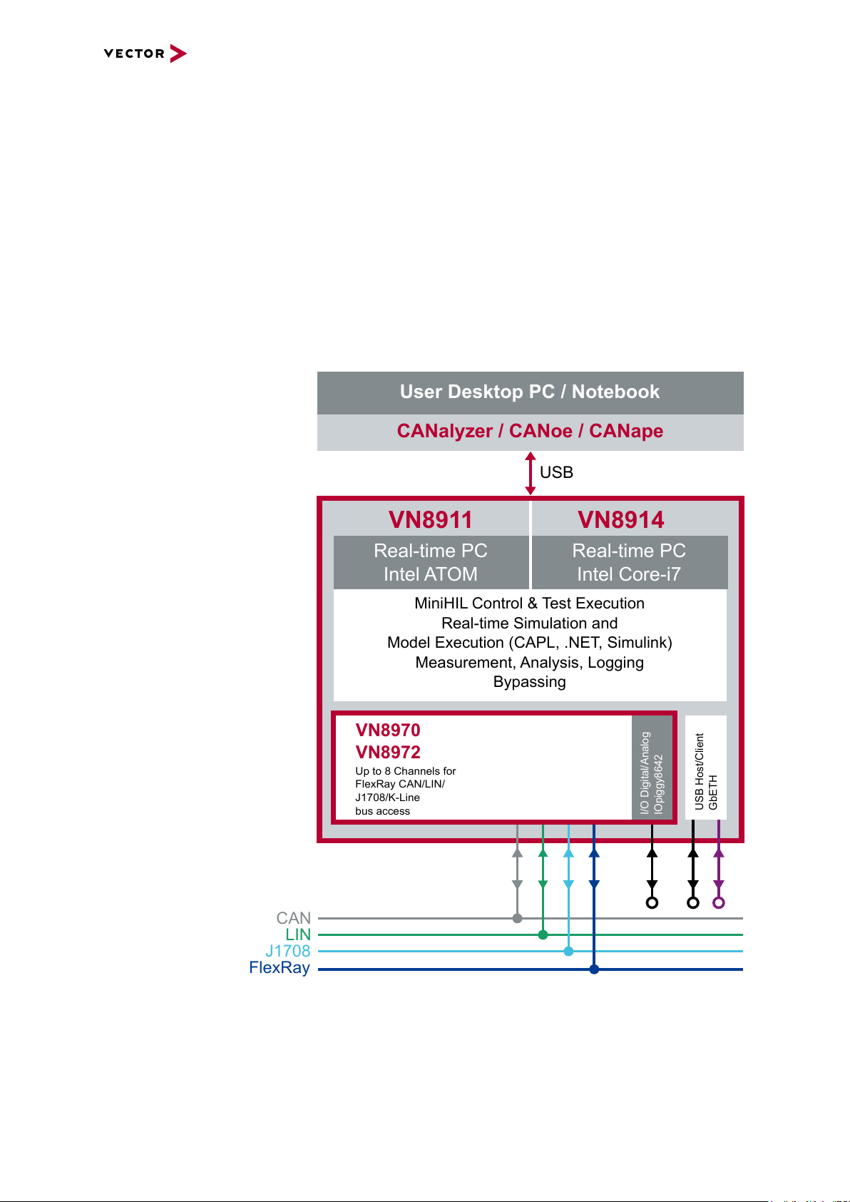
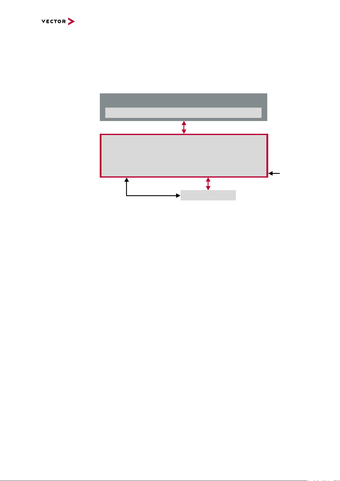
2.1 System Description
User Desktop PC / Notebook
CANalyzer / CANoe / CANape
USB
VN8911
Real-time PC
Intel ATOM
VN8914
Real-time PC
Intel Core-i7
MiniHIL Control & Test Execution
Real-time Simulation and
Model Execution (CAPL, .NET, Simulink)
Measurement, Analysis, Logging
Bypassing
CAN
LIN
J1708
FlexRay
VN8970
VN8972
Up to 8 Channels for
FlexRay CAN/LIN/
J1708/K-Line
bus access
I/O Digital/Analog
IOpiggy8642
2.1.1 Introduction
2 VN8900 Interface Family
Network interface
with real-time
computer
The VN8900 interface family is designed for high-performance applications in combination with CANoe/CANalyzer. The application areas include system simulations or
bypassing applications with Simulink, remaining bus simulations, gateway implementations, test executions (MiniHIL) or data monitoring.
Another key feature is the execution of time-critical CANoe/CANalyzer configurations
without any user PC and without any negative effects on functionality of the running
application.
Figure 1: Operator side ( user PC) and measurement side
VN8900 Interface Family Manual Version 6.0 12
Page 13
2 VN8900 Interface Family
Hardware flexibility Another important VN8900 product characteristic is the modularity of the network inter-
face, which lets users flexibly adapt it to the measurement environment and existing
buses. The overall system is comprised of these components:
> Base Module
Processor unit with memory for executing simulations and time-critical program
sections in stand-alone mode. The Base Module has an Intel processor and basic
port connections for power supply, synchronization, USB and Ethernet. You will
find further details on Base Modules beginning on page 16.
Figure 2: VN8914 back side
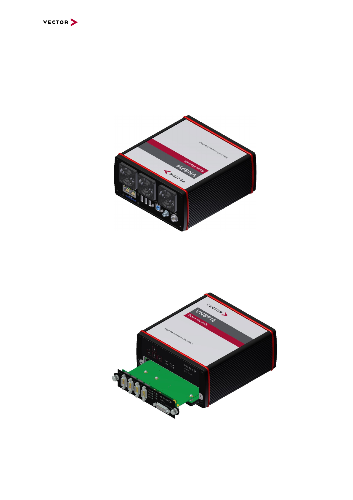
> Plug-In Module
The Plug-In Module represents the actual network interface; it provides the related
interfaces as plug connections (e.g. FlexRay, CAN, LIN or digital-analog input/output). You will find additional details on Plug-In Modules beginning on page
32.
Figure 3: VN8914 with inserted VN8972 FlexRay/CAN/LIN Module
VN8900 Interface Family Manual Version 6.0 13
Page 14

2 VN8900 Interface Family
start-up time
(see technical data)
power/
restart
start time
load user config
auto run measurement
loading time
(depends on config)
total boot-up time
> Piggybacks
Piggybacks establish the connection from the Vector network interface to the user’s electrical networks via appropriate transceivers (FlexRay/CAN/LIN...). Moreover, the Piggyback usually offers the electrical isolation to protect the measurement hardware as well as the system under test.
The amount and kind of supported Piggybacks varies between the Plug-In Modules. Please find the list of valid combinations in section "Transceiver Compatibility" of the accessories manual on the Vector Driver Disk in
\Documentation\Accessories.
Figure 4: Piggyback
2.1.2 Real Time Processing
General When requirements for timing precision are strict, the measurement hardware must be
able to operate with very low latency. The integrated processor of the VN8900 interface family meets this standard and offers significantly improved latency times compared to normal PCs.
CANoe The VN8900 interface family is a real-time hardware that is designed for using with
CANoe. CANoe offers the option of executing real-time relevant simulations and test
functions on the VN8900 – separate from the graphic user interface. On the one hand,
this increases overall system performance, and on the other it enables shorter latency
times and more precise timers. Configuration of the simulation and evaluation are performed on a standard PC (CANoe), while the simulation and test kernel are executed
on the VN8900 (CANoeRT). Communication between the two computers is routed via
a USB cable or via Ethernet (see figure 1).
2.1.3 Stand-Alone Mode
CANoe configuration The VN8900 interface family offers a stand-alone mode which allows a measurement
without any additional user PC.
For this purpose a measurement application can be configured in CANoe, which is
then written into the permanent memory of the VN8900. After a restart, the configuration is loaded and the measurement autonomously started.
Figure 5: Booting overview
VN8900 Interface Family Manual Version 6.0 14
Page 15
2.1.4 Network Extension
VN8911
USB (device)
CANoe / CANalyzer
User Desktop PC / Notebook
e. g. VN1640A
USB (host)
SYNCcable XL
Power
2 VN8900 Interface Family
Additional
network channels
CANoe/CANalyzer supports a single Base Module at a time. To use more network
channels, the VN8900 interfaces offer additional USB (host) ports to connect to other
Vector network interfaces. Time synchronization of the different network interfaces
can be done via the sync line.
Figure 6: Extension example
VN8900 Interface Family Manual Version 6.0 15
Page 16
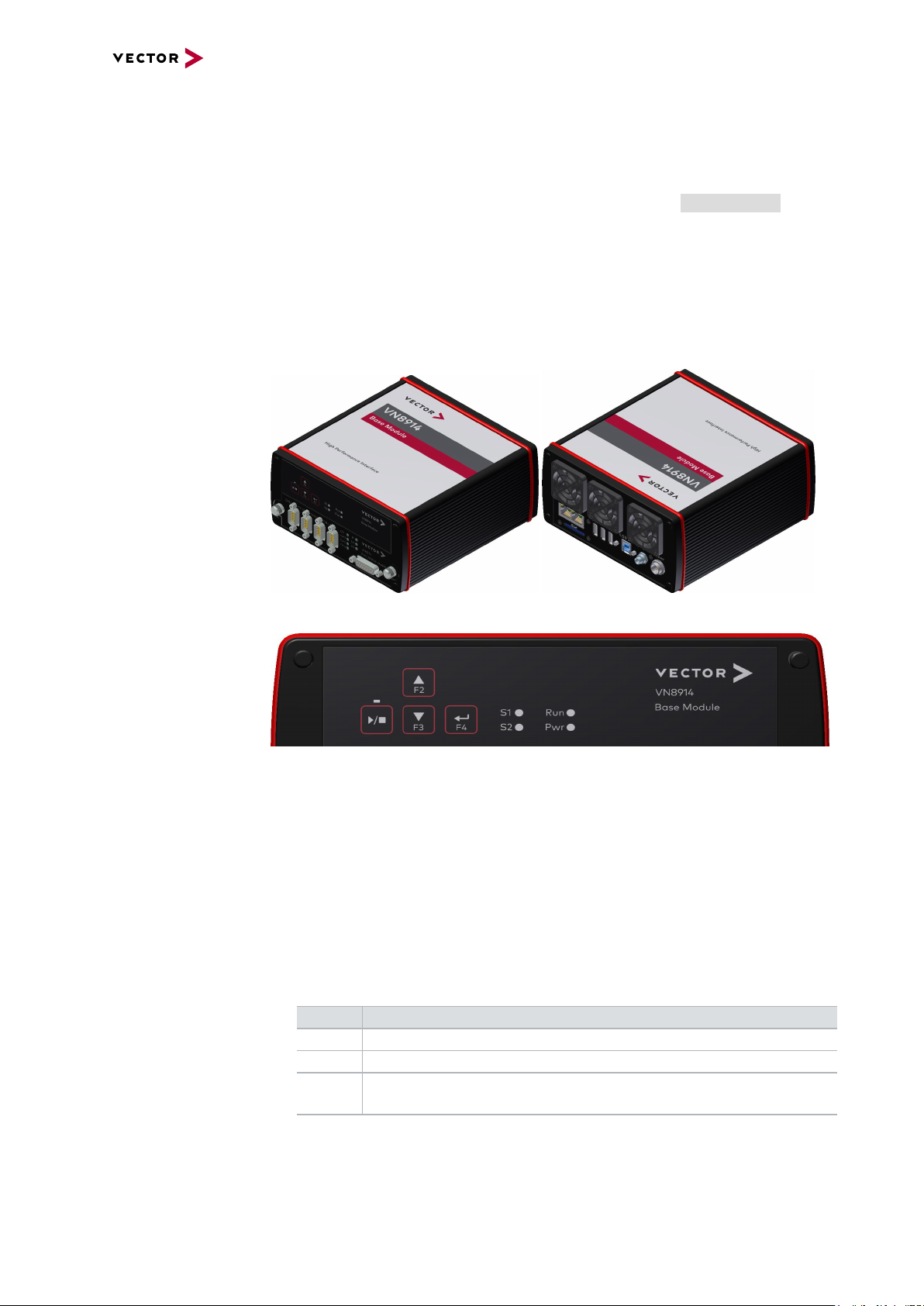
2 VN8900 Interface Family
2.2 Base Modules
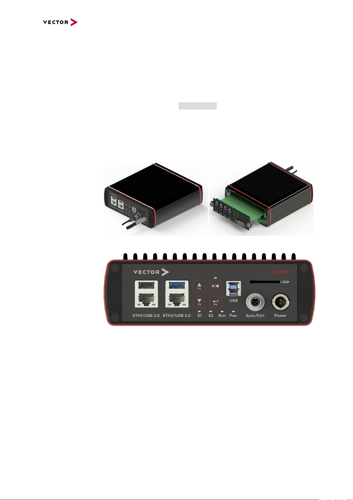
2.2.1 VN8911 Base Module
Description Base Module with integrated Intel Atom processor unit for running real-time appli-
cations. Connection to user networks is provided by a Plug-In Module with individual
bus transceivers (see section Plug-In Module on page 32).
The VN8911 also supports the Vector Tool Platform (VTP). With Extended Real Time
as a part of the Vector Tool Platform, the throughput, latency, and determinism of
CANoe and CANape are improved. To achieve this, the device is logically divided into
two areas. A new area provides Extended Real Time in which predefined functions
can be executed under real-time conditions.
Connections
Figure 7: VN8911 back and front side (with Plug-In Module)
Figure 8: VN8911 back side
> Keypad Start/Stop
This key instantly starts or stops a preconfigured CANoe measurement.
> Keypads F2/F3/F4
These keys can be assigned to CAPL functions.
> LED S1/S2
These LEDs offer a visual feedback for active measurements and can be individually controlled via CAPL.
VN8900 Interface Family Manual Version 6.0 16
Page 17
2 VN8900 Interface Family
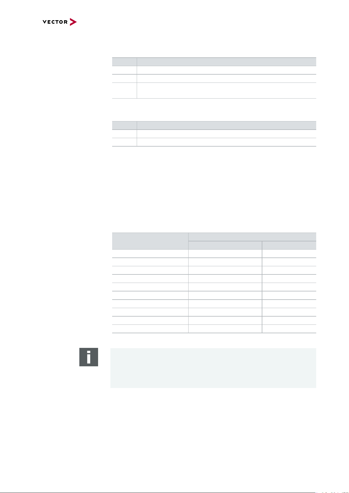
> LEDRun
Multicolored channel LED which indicates the power up/down status.
Color Description
Off Power up/down control line not activated since reboot.
Green Device is running.
Red Inactive power up/down control line. Device shuts down into power-
down mode after time out (has to be defined in CANoe).
> LEDPower
Multicolored channel LED which indicates the power status.
Color Description
Off Power supply disconnected.
Green Power supply connected.
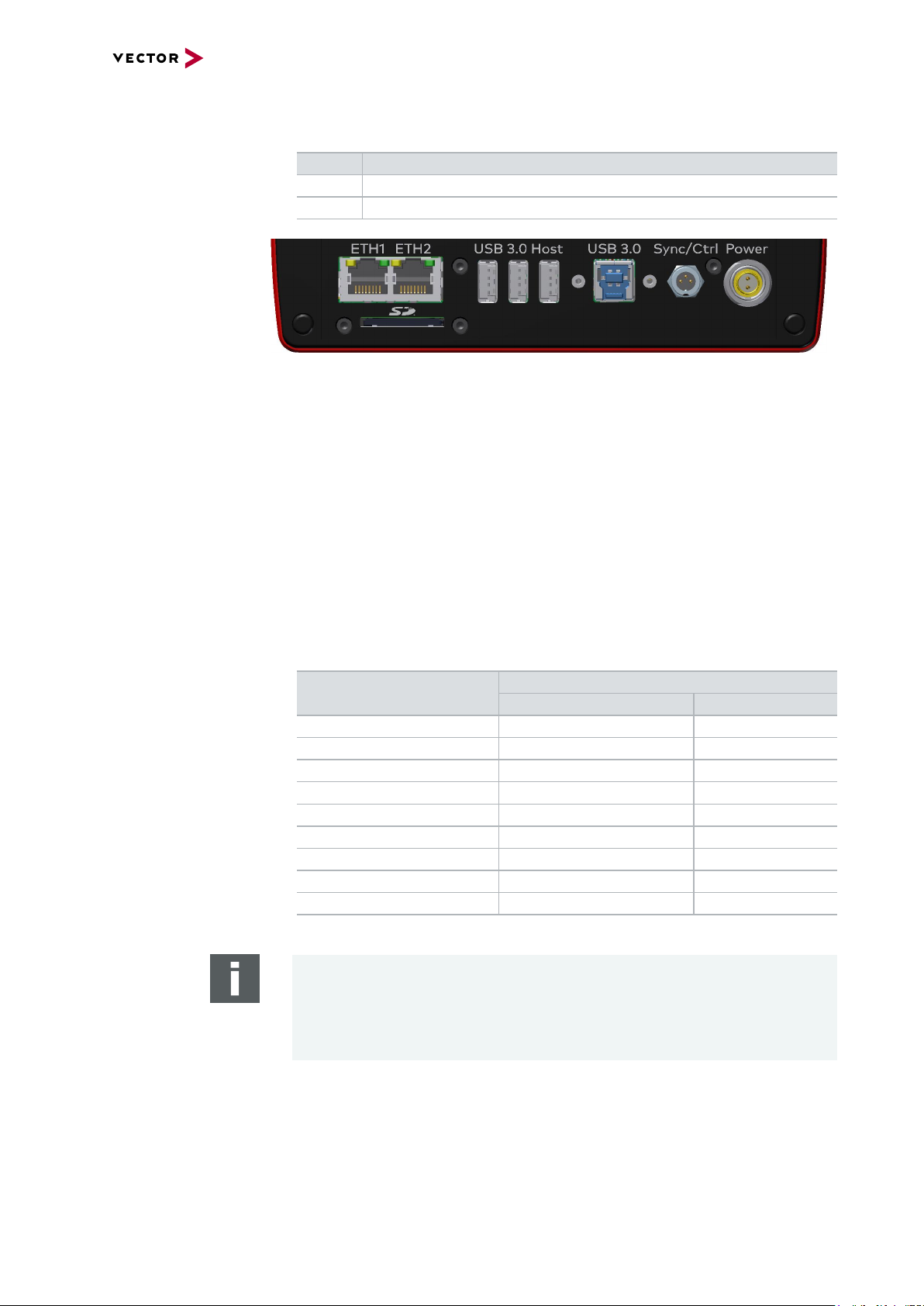
> ETH1/ETH2
These Ethernet ports can be used to connect other Vector Ethernet devices for
use with CANoe, CANalyzer or CANape. Currently supported: VX1121, VX1131,
VX1132, VX1135, VX1060. Furthermore, the Ethernet ports can be used to interconnect your host PC and the VN8911 to use them with measurement applications (e.g. CANoe, CANalyzer).
> USB 2.0/3.0 (host)
These USB ports can be used to connect other Vector USB devices for use with
CANoe or CANalyzer. The summarized output current at these ports is limited to
1050 mA.
Supported Device
externally powered USB powered
Max. Number of Devices
CANcaseXL / log 2 2
VN0601 not applicable 2
VN1630A / VN1640A not applicable 2
VN1630 log 2 2
VN2610/ VN2640 2 not applicable
VN3600 2 not applicable
VN5610 / VN5610A 2 *
VN5640 1 not applicable
VN7600 2 not applicable
VN7640 2 not applicable
* Depending on use-case.
Note
When using the USBhost connector, the Vector device has to be connected to
the VN8911 before powering the VN8911. Please ensure that the USB logo on
the USB cable is on the bottom side (USB pins at top) before connecting. Do not
force the cable into the USB connector to avoid mechanical damages.
> USB (device)
Interconnect your Host PC and the VN8911 via this USB 3.0 port to install the
device on the Host PC and to use it together with measurement applications (e.g.
CANoe, CANalyzer).
VN8900 Interface Family Manual Version 6.0 17
Page 18
2 VN8900 Interface Family
3
1
2
ON
OFF
> SD card slot
This slot can be used for recording use cases.
Recommended cards: Industrial Grade SD, SDHC or SDXC.
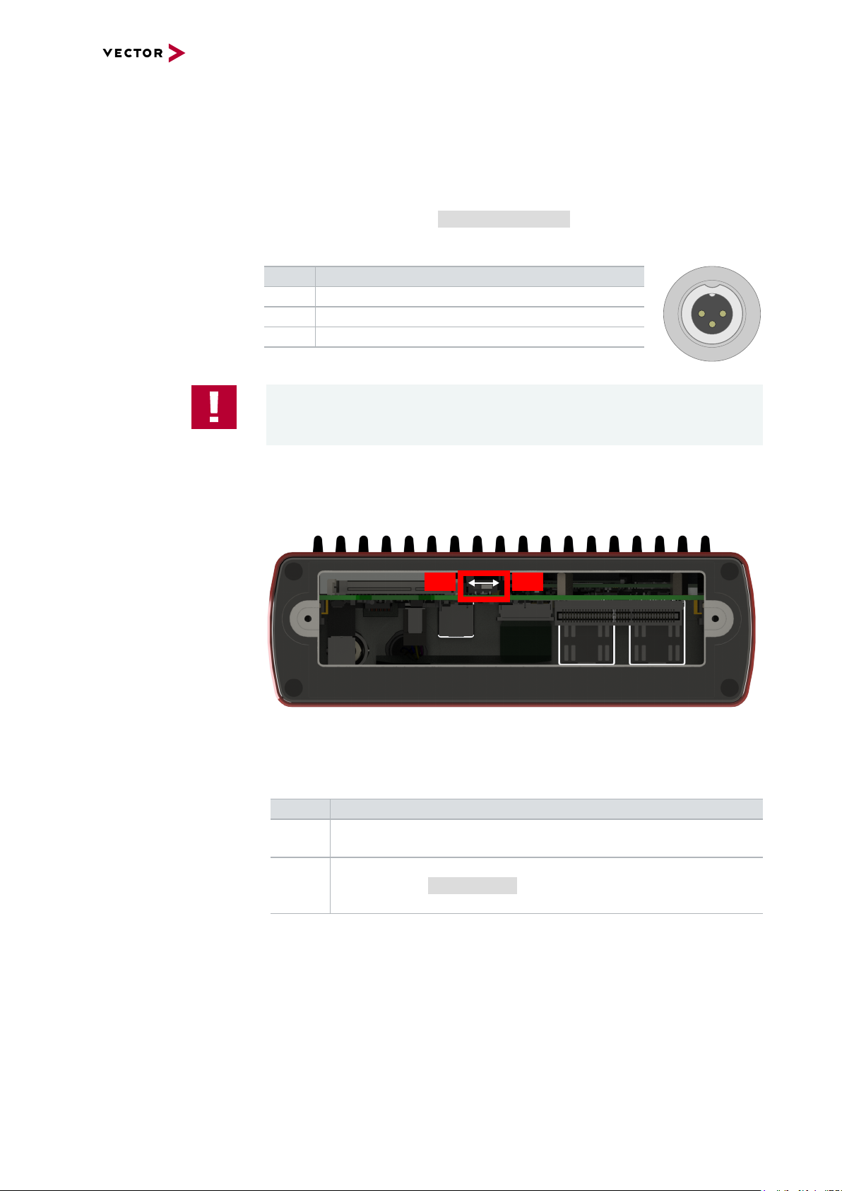
> Sync/Ctrl
This terminal (Binder type 711) can be used for time synchronization of different
Vector devices (see section Time Synchronization on page 74) or to control the
power up/down function of the device.
Pin Assignment
1 Power up/down control line
2 Synchronization line
3 Ground
Caution!
The power up/down control line uses the same reference to GND as the power
supply input of the device, not pin 3 of the sync/ctrl connector.
Power up/down switch
In order to use the power up/down function, switch off the device and remove the
Plug-In Module. Find the power up/down switch underneath the heat sink and set
it to ON.
Figure 9: Power up/down switch in VN8911
Reassemble the Plug-In Module and connect the power supply. Depending on the
voltage at the power up/down control line, the VN8911 can be powered up or shut
down.
Ctrl Description
0 V If running, the device shuts down after time out (approx. 5 seconds).
Otherwise the device remains in power-up mode.
> 5 V If in power-down mode, the device powers up (please note the start-up
time in section Technical data on page 21). Current consumption in
power-down mode: 2.9mA, max.104mW@36 V.
VN8900 Interface Family Manual Version 6.0 18
Page 19
2 VN8900 Interface Family
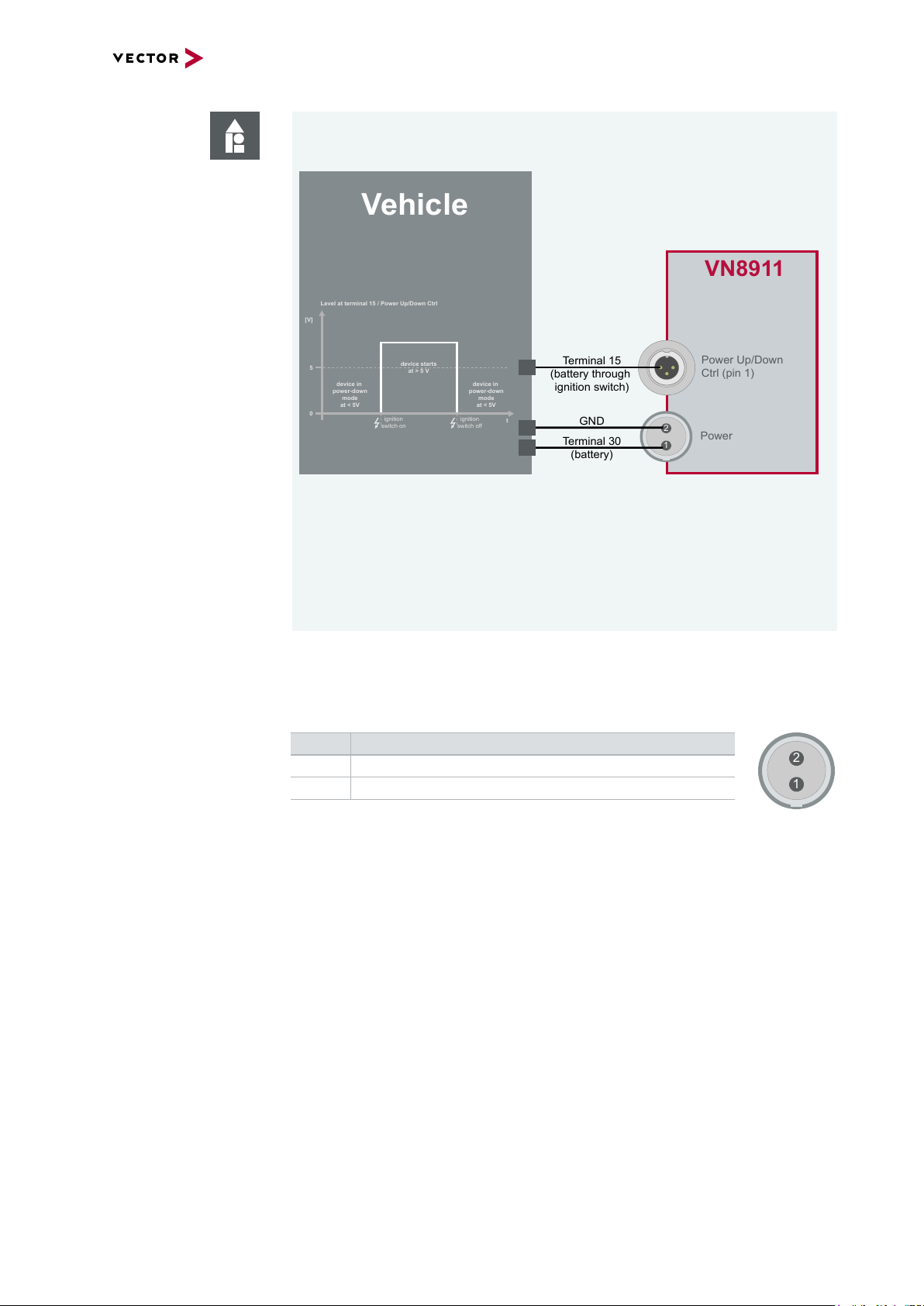
GND
Terminal 30
(battery)
Terminal 15
(battery through
ignition switch)
VN8911
Power Up/Down
Ctrl (pin 1)
Vehicle
Power
1
2
3
1
2
Level at terminal 15 / Power Up/Down Ctrl
[V]
5
0
device in
power-down
mode
at < 5V
t
ignition
switch on
device starts
at > 5 V
device in
power-down
mode
at < 5V
ignition
switch off
1
2
Example
With this wiring, the VN8911 powers up and down with the ignition switch of the
vehicle.
You can use the following Vector accessories to connect the VN8911 to the
vehicle:
> Power up/down control
Connection Cable Binder Type 711 (3-pin), part number 30011
> Power
ODU Connector / Bunch Plugs, part number 05069
> Power
For its power supply, the VN8911 has a two-pin ODU connector (MINI-SNAP
size1, type GG1L0C-P02RP00-0000). Attach the enclosed power cable to power
up the unit (matching ODU connector type S11L0C-P02NPL0-6200).
Pin Assignment
2 GND
1 +
VN8900 Interface Family Manual Version 6.0 19
Page 20
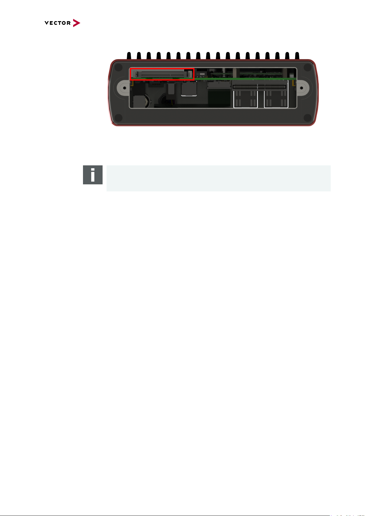
CFast card
2 VN8900 Interface Family
Figure 10: CF ast card slot in VN8911
The VN8911 operating system is stored on a CFast card and must not be removed during operation.
Note
The CFast card should only be removed for system recoveries. Please contact the
Vector support for further instructions on system recoveries.
VN8900 Interface Family Manual Version 6.0 20
Page 21
2 VN8900 Interface Family
Technical data
VN8911
Processor Intel ATOM E3845
Quad-Core with 1.91 GHz
Memory 4 GB
Hard drive CFast card, 16 GB
Transceiver Depends on the Plug-In Module
and its Piggybacks
PC interface USB 3.0 SuperSpeed
Temperature range Operating: -40 °C...+60 °C
Shipping and storage: -40 °C...+85 °C
Relative humidity of ambient air 15 %...95 %, non-condensing
USB 1/2 output current Max. 1050 mA, both ports combined
External power supply 6 V...36 V DC
Power-up: 9 V DC
Power consumption Typ. 7.0 W without Plug-In Module
Start-up time Approx. 30 seconds
Dimensions (LxWxH) 190 mm x 170 mm x 60 mm
(with Plug-In Module)
Operating system requirements Windows 7 SP1 (32 bit / 64 bit)
Windows 8.1 (32 bit / 64 bit)
Windows 10 (64 bit)
Ethernet 1000Base-T/100Base-TX/10Base-T
Supported Plug-In Modules VN8970
Note
EUROPE - Information according REACh:
The battery required for the real-time clock contains 1,2-Dimethoxyethane.
VN8900 Interface Family Manual Version 6.0 21
Page 22
2 VN8900 Interface Family
2.2.2 VN8914 Base Module
Description Base Module with integrated Intel Core-i7 processor unit for running real-time appli-
cations with high performance demands. Connection to user networks is provided by
a Plug-In Module with individual bus transceivers (see section Plug-In Module on page
32).
The VN8914 also supports the Vector Tool Platform (VTP). With Extended Real Time
as a part of the Vector Tool Platform, the throughput, latency, and determinism of
CANoe and CANape are improved. To achieve this, the device is logically divided into
two areas. A new area provides Extended Real Time in which predefined functions
can be executed under real-time conditions.
Keypads/LEDs
Figure 11: VN8914 front and back side (with Plug-In Module)
Figure 12: VN8914 front side
> Keypad Start/Stop
This key instantly starts or stops a preconfigured CANoe measurement.
> Keypads F2/F3/F4
These keys can be assigned to CAPL functions.
> LED S1/S2
These LEDs offer a visual feedback for active measurements and can be individually controlled via CAPL.
> LEDRun
Multicolored channel LED which indicates the power up/down status.
Color Description
Off Power up/down control input < 5V. Device in power down mode.
Green Device is running (power up/down control input > 5V).
Red Device shuts down into power down mode after time out if power up/-
down feature is enabled.
VN8900 Interface Family Manual Version 6.0 22
Page 23
Connectors
2 VN8900 Interface Family
> LEDPower
Multicolored channel LED which indicates the power status.
Color Description
Off Device is not powered.
Green Device is powered.
Figure 13: VN8914 back side
> ETH1/ETH2
These Ethernet ports can be used to connect other Vector Ethernet devices for
use with CANoe, CANalyzer or CANape. Currently supported: VX1060, VX1121,
VX1131, VX1132, VX1135. Furthermore, the Ethernet ports can be used to interconnect your host PC and the VN8914 to use them with measurement applications (e.g. CANoe, CANalyzer).
> SD card slot
This slot can be used for recording use cases.
Recommended cards: Industrial Grade SD, SDHC or SDXC.
> USB 3.0 Host
These three host ports are used to connect other Vector USB devices for use with
CANoe or CANalyzer. The summarized output current at these ports is limited to
1350 mA.
Supported Device
externally powered USB powered
Max. Number of Devices
CANcaseXL / log 3 2*
VN0601 not applicable 2*
VN1630A / VN1640A not applicable 2
VN2610 / VN2640 3 not applicable
VN3600 3 not applicable
VN5610 / VN5610A 3 **
VN5640 3 not applicable
VN7600 3 not applicable
VN7640 3 not applicable
* Depending on use-case.
Note
When using the USBhost connector, the Vector device has to be connected to
the VN8914 before powering the VN8914. Please ensure that the USB logo on
the USB cable is on the bottom side (USB pins at top) before connecting. Do not
force the cable into the USB connector to avoid mechanical damages.
VN8900 Interface Family Manual Version 6.0 23
Page 24
2 VN8900 Interface Family
3
1
2
ON
OFF
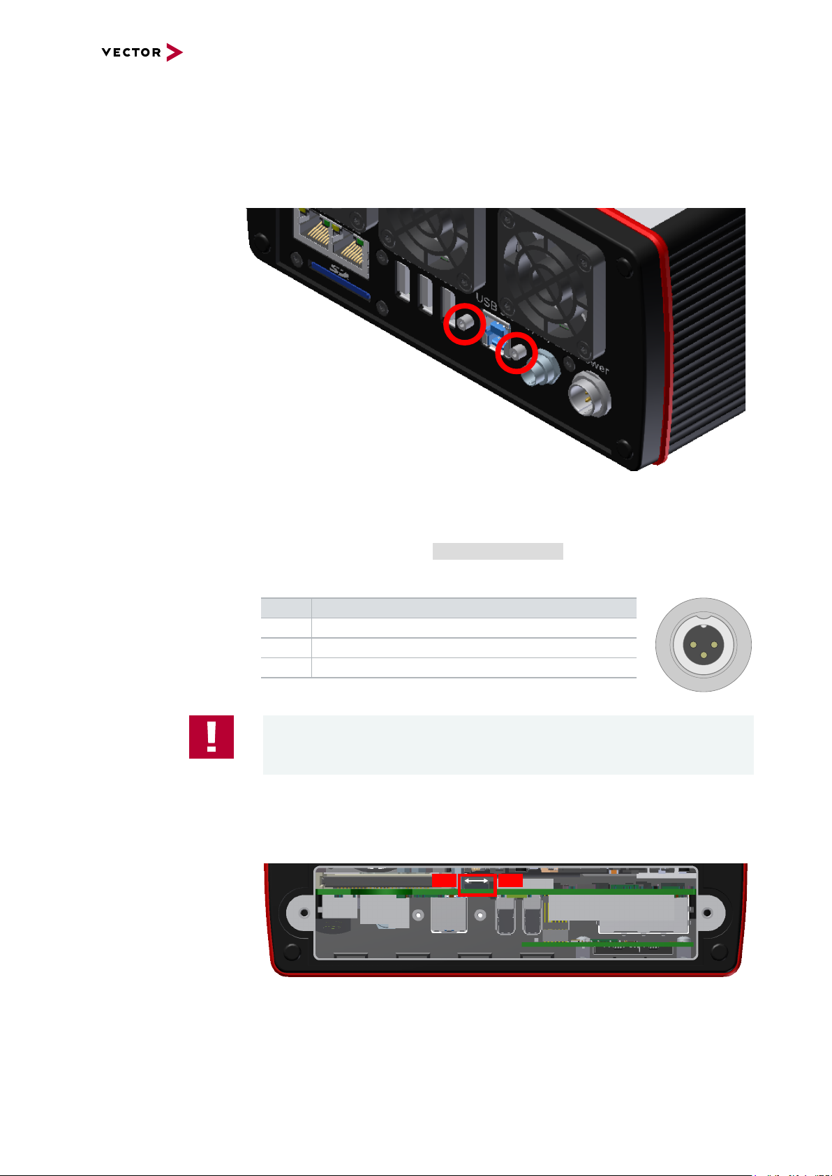
> USB 3.0
Interconnect your Host PC and the VN8914 via this USB 3.0 port to install the
device on the Host PC and to use it together with measurement applications (e.g.
CANoe, CANalyzer). The USB 3.0 connector has two stand offs to securely
attach the appropriate USB 3.0 cable (see accessories manual).
Power up/down switch
Figure 14: USB 3.0 stand offs
> Sync/Ctrl
This terminal (Binder type 711) can be used for time synchronization of different
Vector devices (see section Time Synchronization on page 74) or to control the
power up/down function of the device.
Pin Assignment
1 Power up/down control line
2 Synchronization line
3 Ground
Caution!
The power up/down control line uses the same reference to GND as the power
supply input of the device, not pin 3 of the sync/ctrl connector.
In order to use the power up/down function, switch off the device and remove the
Plug-In Module. Find the power up/down switch underneath the heat sink and set
it to ON.
Figure 15: Power up/down switch in VN8914
VN8900 Interface Family Manual Version 6.0 24
Page 25

2 VN8900 Interface Family
GND
Terminal 30
(battery)
Terminal 15
(battery through
ignition switch)
VN8914
Power Up/Down
Ctrl (pin 1)
Vehicle
Power
1
2
3
1
2
Level at terminal 15 / Power Up/Down Ctrl
[V]
5
0
device in
power-down
mode
at < 5V
t
ignition
switch on
device starts
at > 5 V
device in
power-down
mode
at < 5V
ignition
switch off
Reassemble the Plug-In Module and connect the power supply. Depending on the
voltage at the power up/down control line, the VN8914 can be powered up or shut
down.
Ctrl Description
0 V If running, the device shuts down after time out (approx. 5 seconds).
Otherwise the device remains in power-up mode.
> 5 V If in power-down mode, the device powers up (please note the start-up
time in section Technical data on page 27). Current consumption in
power-down mode: 3.6mA@10 V...36 V.
Example
With this wiring, the VN8914 powers up and down with the ignition switch of the
vehicle.
You can use the following Vector accessories to connect the VN8914 to the
vehicle:
> Power up/down control
Connection Cable Binder Type 711 (3-pin), part number 30011
> Power
ODU Connector / Bunch Plugs, part number 05069
VN8900 Interface Family Manual Version 6.0 25
Page 26

1
2
CFast card
2 VN8900 Interface Family
> Power
For its power supply, the VN8914 has a two-pin ODU connector (MINI-SNAP
size1, type GG1L0C-P02RP00-0000). Attach the enclosed power cable to power
up the unit (matching ODU connector type S11L0C-P02NPL0-6200).
Pin Assignment
2 GND
1 +
Figure 16: CF ast card slot in VN8914
The VN8914 operating system is stored on a CFast card and must not be removed during operation.
Note
The CFast card should only be removed for system recoveries. Please contact the
Vector support for further instructions on system recoveries.
Note
Please check all fan covers of the VN8914 for impurities (e.g. dust) at regular intervals, depending on environmental conditions. For example, impurities can be
removed with an appropriate vacuum cleaner.
VN8900 Interface Family Manual Version 6.0 26
Page 27

2 VN8900 Interface Family
Technical data
VN8914
Processor Intel Core-i7 6822EQ CPU
Memory 8 GB
Hard drive CFast card, 16 GB
Transceiver Depends on the Plug-In Module
and its Piggybacks
Ethernet port 2x GbETH
USB host interfaces 3x USB 3.0 SuperSpeed
PC interface USB 3.0 SuperSpeed
Temperature range Operating: 0 °C...+50 °C
Shipping and storage: -40 °C...+85 °C
Relative humidity of ambient air 15 %...95 %, non-condensing
USB 1/2/3 output current Max. 1350 mA, all ports combined
External power supply 10 V...36 V DC
Power consumption Typ. 18 W @ 24 V without Plug-In Module
Start-up time Approx. 25 seconds
Dimensions (LxWxH) 190 mm x 170 mm x 60 mm
(with Plug-In Module)
Operating system requirements Windows 7 SP1 (32 bit / 64 bit)
Windows 8.1 (32 bit / 64 bit)
Windows 10 (64 bit)
Ethernet 1000Base-T/100Base-TX/10Base-T
Supported Plug-In Modules VN8970, VN8972
Note
EUROPE - Information according REACh:
> Diboron trioxide (CAS no. 1303-86-2)
> Lead oxide sulfate (CAS no. 12036-76-9)
> 1,2-dimethoxyethane; ethylene glycol dimethyl ether (EGDME)
(CAS no. 110-71-4)
VN8900 Interface Family Manual Version 6.0 27
Page 28

2 VN8900 Interface Family
2.2.3 VN8912 / VN8912A Base Module
Description Base Module with integrated Intel Core-i7 processor unit for running real-time appli-
cations with high performance demands. Connection to user networks is provided by
a Plug-In Module with individual bus transceivers (see section Plug-In Module on page
32).
VN8912A The main features as well as the technical data of the VN8912A are identical to the
VN8912. In addition, the VN8912A also supports the Vector Tool Platform (VTP).
With Extended Real Time as a part of the Vector Tool Platform, the throughput,
latency, and determinism of CANoe and CANape are improved. To achieve this, the
device is logically divided into two areas. A new area provides Extended Real Time in
which predefined functions can be executed under real-time conditions.
Front side
Figure 17: VN8912 front side (with VN8970 Plug-In Module)
Figure 18: VN8912 front side
> Keypad Start/Stop
This key instantly starts or stops a preconfigured CANoe measurement.
> Keypads F2/F3/F4
These keys can be assigned to CAPL functions.
> LED S1/S2
These LEDs offer a visual feedback for active measurements and can be individually controlled via CAPL.
VN8900 Interface Family Manual Version 6.0 28
Page 29

CFast card
2 VN8900 Interface Family
Figure 19: CF ast card slot in VN8912
The VN8912 operating system is stored on a CFast card and must not be removed during operation.
Note
The CFast card should only be removed for system recoveries. For this purpose, a
separate CFast card reader is included in the delivery. Please contact the Vector
support for further instructions on system recoveries.
Back side
Figure 20: VN8912 back side
> ETH 1/2
Two independent Ethernet connections (RJ45) for Vector devices.
Currently supported: VX1060, VX1121, VX1131, VX1132, VX1135.
> USB 1/2/3/4 (host)
These four host ports are used to connect other Vector USB devices for use with
CANoe or CANalyzer. The summarized output current at these ports is limited to
1350 mA.
Supported Device
externally powered USB powered
Max. Number of Devices
CANcaseXL / log 4 2*
VN0601 not applicable 2*
VN1630A / VN1640A not applicable 2
VN2610 / VN2640 4 not applicable
VN3600 4 not applicable
VN5610 / VN5610A 4 **
VN8900 Interface Family Manual Version 6.0 29
Page 30

2 VN8900 Interface Family
3 1
2
1
2
Supported Device
externally powered USB powered
Max. Number of Devices
VN5640 4 not applicable
VN7600 4 not applicable
VN7640 4 not applicable
* Athird/fourth Vector device has to be externally powered.
** Depending on use-case.
Note
The Vector device has to be connected to the VN8912 before powering the
VN8912.
> USB (device)
Interconnect your Host PC and the VN8912 via this USB port to install the device
on the Host PC and to use it together with measurement applications (e.g.
CANoe, CANalyzer).
> Sync
This terminal (Binder type 711) can be used for time synchronization of different
Vector devices (see section Time Synchronization on page 74).
Pin Assignment
1 Not connected
2 Synchronization line
3 Ground
> Power
For its power supply, the VN8912 has a two-pin ODU connector (MINI-SNAP
size1, type GG1L0C-P02RP00-0000). Attach the enclosed power cable to power
up the unit (matching ODU connector type S11L0C-P02NPL0-6200).
Pin Assignment
1 +
2 GND
Note
Please check all fan covers of the VN8912 for impurities (e.g. dust) at regular intervals, depending on environmental conditions. For example, impurities can be
removed with an appropriate vacuum cleaner.
VN8900 Interface Family Manual Version 6.0 30
Page 31

2 VN8900 Interface Family
Technical data
VN8912(A)
Processor Intel Core-i7, 2x 1.7 GHz, 4 MB Cache
Memory 4 GB
Hard drive CFast card, 8 GB (two partitions, 4 GB each)
Transceiver Depends on the Plug-In Module
and its Piggybacks
PC interface USB 3.0, SuperSpeed
Temperature range Operating: 0 °C...+50 °C
Shipping and storage: -40 °C...+85 °C
Relative humidity of ambient air 15 %...95 %, non-condensing
USB 1/2/3/4 output current Max. 1350 mA, all four ports combined
External power supply 10 V...36 V DC
Power consumption Typ. 16 W @ 24 V without Plug-In Module
Start-up time Approx. 25 seconds
Dimensions (LxWxH) 183 mm x 172 mm x 85 mm
(without Plug-In Module)
190 mm x 172 mm x 85 mm
(with Plug-In Module)
Operating system requirements
on Host PC
Windows 7 SP1 (32 bit / 64 bit)
Windows 8.1 (32 bit / 64 bit)
Windows 10 (64 bit)
Ethernet 1000Base-T/100Base-TX/10Base-T
Supported Plug-In Modules VN8912: VN8950/VN8970/VN8972
VN8912A: VN8970/VN8972
Note
EUROPE - Information according REACh:
The battery required for the real-time clock contains 1,2-Dimethoxyethane.
VN8900 Interface Family Manual Version 6.0 31
Page 32

2 VN8900 Interface Family
Channel 9
Channel 1
Channel 3
Channel 4
Channel 2
2.3 Plug-In Module
2.3.1 VN8970 FlexRay/CAN/LIN Module
Description The VN8970 FlexRay/CAN/LIN Module is a Plug-In Module for VN8912(A)/VN8914
and has a FlexRay channel as well as several CAN/LIN channels. In addition, a ninth
channel is available for dedicated digital-analog input/output tasks.
VN8970 with five
plug-in locations
for transceivers
Figure 21: VN8970 FR/CAN/LIN Module with Piggyback plug-in locations
Bus configuration The Plug-In Module’s greatest asset is its five plug-in locations for add-ons (primary
channels). Depending on requirements, electrically isolated CAN High-Speed, CAN
Low-Speed, CAN Single Wire, J1708, LIN or FlexRay transceivers (Piggybacks) may
be used. In addition, four capacitively decoupled built-in CAN TJA1051 (high-speed)
transceivers are available (secondary channels).
In the plug-in location for channel 1, an FRpiggy can be inserted for a two-channel
FlexRay connection (A and B of a cluster). Alternatively, a CANpiggy or LINpiggy can
be used. Channels 2 to 4 are reserved for CANpiggies and LINpiggies. CANpiggies
must be populated in ascending order; LINpiggies in descending order (see
examples). J1708 should be handled like CAN.
Channel 9 is reserved for dedicated IO Piggybacks.
Note
Inserting order
FRpiggy: CH1.
LINpiggies: CH4…CH1.
CAN/J1708piggies: CH1…CH4, but after an FRpiggy and before LINpiggies.
VN8900 Interface Family Manual Version 6.0 32
Page 33

2 VN8900 Interface Family
Piggyback
order
Primary CH1 CH2 CH3 CH4 CH9
FlexRay
or CAN1
Piggyback IO
or
LIN4
CAN2
or
LIN3
CAN3
or
LIN2
CAN4
or
LIN1
Secondary CH5 CH6 CH7 CH8 Built-in
Transceiver
CAN
1051cap
CAN
1051cap
CAN
1051cap
CAN
1051cap
-
Note
CH5, CH6, CH7, and CH8 are equipped with built-in CAN TJA1051 transceivers.
CH5 will be deactivated if an FRpiggy is inserted in the plug-in location for channel
1 and the pin assignment accordingly set via the DIP switches.
Each empty plug-in location (except for CH9) is loaded with a built-in transceiver
from the secondary channel according to the DIP switch settings.
Reference
Further information on DIP switches can be found on page 37.
VN8900 Interface Family Manual Version 6.0 33
Page 34

2 VN8900 Interface Family
Examples The following tables show examples of possible configurations (a list of all possible
channel configurations can be found in section Technical data on page 43):
4x CAN
without Piggybacks
CH1/CH5 CH2/CH6 CH3/CH7 CH4/CH8
Piggyback - - - - Primary CH1 CH2 CH3 CH4 CH9
Ç Ç Ç Ç
Built-in
Transceiver
CAN
1051cap
CAN
1051cap
CAN
1051cap
Secondary CH5 CH6 CH7 CH8
Configuration CH1: no Piggyback, built-in CAN 1051cap transceiver (CH5).
CH5: not usable.
CH2: no Piggyback, built-in CAN 1051cap transceiver (CH6).
CH6: not usable.
CH3: no Piggyback, built-in CAN 1051cap transceiver (CH7).
CH7: not usable.
CH4: no Piggyback, built-in CAN 1051cap transceiver (CH8).
CH8: not usable.
CH9: no Piggyback.
8x CAN
1x IO
CH9
CAN
1051cap
Piggyback CAN CAN CAN CAN IO
Primary CH1 CH2 CH3 CH4 CH9
Built-in
Transceiver
Secondary CH5 CH6 CH7 CH8
Configuration CH1: CANpiggy.
CH5: built-in CAN 1051cap transceiver.
CH2: CANpiggy.
CH6: built-in CAN 1051cap transceiver.
CH3: CANpiggy.
CH7: built-in CAN 1051cap transceiver.
CH4: CANpiggy.
CH8: built-in CAN 1051cap transceiver.
CH9: IOpiggy.
CH1/CH5 CH2/CH6 CH3/CH7 CH4/CH8
-
CAN
1051cap
CAN
1051cap
CAN
1051cap
CAN
1051cap
CH9
VN8900 Interface Family Manual Version 6.0 34
Page 35

1x FlexRay A/B
6x CAN
2 VN8900 Interface Family
Piggyback FlexRay CAN CAN CAN -
Primary CH1 CH2 CH3 CH4 CH9
Built-in
Transceiver
Secondary CH5 CH6 CH7 CH8
Configuration CH1: FRpiggy.
CH5: not usable due to FRpiggy.
CH2: CANpiggy.
CH6: built-in CAN 1051cap transceiver.
CH3: CANpiggy.
CH7: built-in CAN 1051cap transceiver.
CH4: CANpiggy.
CH8: built-in CAN 1051cap transceiver.
CH9: no Piggyback.
1x FlexRay A/B
3x CAN
1x LIN
1x IO
Piggyback FlexRay - - LIN IO
Primary CH1 CH2 CH3 CH4 CH9
Built-in
Transceiver
Secondary CH5 CH6 CH7 CH8
CH1/CH5 CH2/CH6 CH3/CH7 CH4/CH8
-
/
CAN
1051cap
CAN
1051cap
CAN
1051cap
CH1/CH5 CH2/CH6 CH3/CH7 CH4/CH8
-
/
Ç Ç
CAN
1051cap
CAN
1051cap
-
CAN
1051cap
CH9
CH9
Configuration CH1: FRpiggy.
CH5: not usable due to FRpiggy.
CH2: no Piggyback, built-in CAN 1051cap transceiver (CH6).
CH6: not usable.
CH3: no Piggyback, built-in CAN 1051cap transceiver (CH7).
CH7: not usable.
CH4: LINpiggy.
CH8: built-in CAN 1051cap transceiver.
CH9: IOpiggy.
VN8900 Interface Family Manual Version 6.0 35
Page 36

1x FlexRay A/B
4x CAN
1x LIN
Piggyback FlexRay CAN - LIN -
Primary CH1 CH2 CH3 CH4 CH9
Built-in
Transceiver
Secondary CH5 CH6 CH7 CH8
Configuration CH1: FRpiggy.
CH5: not usable due to FRpiggy.
CH2: CANpiggy.
CH6: built-in CAN 1051cap transceiver.
CH3: no Piggyback, built-in CAN 1051cap transceiver (CH7).
CH7: not usable.
2 VN8900 Interface Family
CH1/CH5 CH2/CH6 CH3/CH7 CH4/CH8
- -
/
CAN
1051cap
Ç
CAN
1051cap
-
CAN
1051cap
CH9
CH4: LINpiggy.
CH8: built-in CAN 1051cap transceiver.
CH9: no Piggyback.
Reference
See the separate accessories manual for a list of available Piggybacks.
VN8900 Interface Family Manual Version 6.0 36
Page 37

2 VN8900 Interface Family
Channel 9
CH 1/5
CH 3/7
CH 4/8
CH 2/6
1
6
ON
A
1
6
ON
B
No piggy
installed
Double assignment of
D-SUB9 connectors
Before installing a Piggyback in the plug-in location, the pin assignment of the DSUB9 connector has to be selected via DIP switches, which can be found at the plugin locations.
Pin assignment
CH1 … CH8
Figure 22: Channel 1...8 with DIP switches
The pin assignments of the D-SUB9 connectors depend on the used bus transceiver
configuration inside the VN8970. A list of available Piggybacks and their D-SUB9 pin
assignments is included in the separate accessories manual on the Vector Driver
Disk.
> No Piggyback inserted
If no Piggyback is inserted, only the
built-in CAN transceiver is active (no
double assignment at the D-SUB9 connector):
Pin Assignment
1 Not connected
2 1051cap CAN Low
3 GND
4 Not connected
5 Shield
6 Not connected
7 1051cap CAN High
8 Not connected
9 Not connected
Setting of DIP switches
A: all ‚off’ / B: all ‚on’
VN8900 Interface Family Manual Version 6.0 37
Page 38

> CAN/LIN Piggyback inserted
1
6
ON
A
1
6
ON
B
CAN/LINpiggy
installed
5
4
3
2
1
6
7
8
9
Shield
1041Amag VB+
1041Amag Split
1051cap CAN High
1041Amag VB-
1041Amag CAN Low
1051cap CAN Low
1051cap GND
1041Amag CAN High
Shield
CH1 CH5
If a CAN- or LINpiggy is inserted, the pin
assignment at the D SUB9 connector is
as follows:
Pin Assignment
1 1051cap CAN Low
2 Piggyback-dependent
3 Piggyback-dependent
4 Piggyback-dependent
5 Shield
6 GND
7 Piggyback-dependent
8 1051cap CAN High
9 Piggyback-dependent
Example
2 VN8900 Interface Family
Setting of DIP switches
A: all ‚on’ / B: all ‚off’
CANpiggy 1041Amag
The following example shows the pin assignment of CH1 and CH5 if a CANpiggy
1041Amag is inserted in the plug-in location 1.
VN8900 Interface Family Manual Version 6.0 38
Page 39

2 VN8900 Interface Family
CAN Low
2 2
GND / VB-
3 3
CAN High / LIN
7 7
Special function
4 4
CAN Low
1 2
GND
6 3
CAN High
8 7
Shield
5 5
Shield
5 5
(VB+)
9 9
VN8970
CH1/5
CAN Low
2 2
GND / VB-
3 3
CAN High / LIN
7 7
Special function
4 4
CAN Low
1 2
GND
6 3
CAN High
8 7
Shield
5 5
Shield
5 5
(VB+)
9 9
VN8970
CH2/6
CH1 (A)
CH5 (B)
CH2 (A)
CH6 (B)
CAN/LIN Y cable Use the CANcable 2Y to access both channels on separate D-SUB9 connectors
(see accessories manual, part number 05075).
Figure 23: Example with 2x CANcable 2Y connected to VN8970
VN8900 Interface Family Manual Version 6.0 39
Page 40

> FlexRay Piggyback inserted
1
6
ON
A
1
6
ON
B
FRpiggy
installed
(only CH1)
5
4
3
2
1
6
7
8
9
Shield
BP B
FR GND
BM A
Trigger
open-collector output,
5 V low-active
BP A
Shield
Channel A Channel B
BM B
FR GND
If an FRpiggy is inserted, the pin assignment at the D SUB9 connector is as follows:
Pin Assignment
1 Piggyback-dependent
2 FlexRay BM A
3 FlexRay GND
4 FlexRay BM B
5 Shield
6 Piggyback-dependent
7 FlexRay BP A
8 FlexRay BP B
9 Piggyback-dependent
Example
2 VN8900 Interface Family
Setting of DIP switches
A: all ‚off’ / B: all ‚off’
FRpiggy 1082cap
The following example shows the pin assignment of the FlexRay channels A and B
at CH1 if an FRpiggy 1082cap is inserted in the plug-in location 1 (CH5 is disabled).
FlexRay Y cable Use the FRcableAB to access channel A and B on separate D-SUB9 connectors
(see accessories manual).
VN8900 Interface Family Manual Version 6.0 40
Page 41

Connections
2 VN8900 Interface Family
Figure 24: VN8970 with 4x D-SUB9 and 1x D-SUB15
> CH1
D-SUB9 connector for FlexRay, CAN or LIN (depending on Piggyback).
> CH2 … CH4
D-SUB9 connector for CAN or LIN (depending on Piggyback).
> CH5
Fix CAN TJA1051cap (not available if FlexRay is being used at CH1).
> CH6 … CH8
Fix CAN TJA1051cap.
> CH9
D-SUB15 socket for versatile tasks with the IOpiggy 8642. A detailed description
can be found in the separate accessories manual on the Vector Driver Disk in
\Documentation\Accessories.
LEDs > CH1 … CH4 (with CAN-/LINpiggies)
Multicolored channel LEDs, each indicating the bus activity for CAN or LIN.
Color Description
Green Data frames have been sent or received correctly.
The flashing frequency varies according to the message rate.
Orange Error frames have been sent or received.
The flashing frequency varies according to the message rate.
Red Bus off.
> CH1 (with FRpiggy)
Multicolored channel LED which indicates the sync state of FlexRay.
Color Description
Off FlexRay Communication Controller offline.
Green FlexRay Communication Controller synchronized.
Orange FlexRay Communication Controller not synchronized.
Red Error.
> A/B
Lights up, when data is received or transmitted on channel A/B.
VN8900 Interface Family Manual Version 6.0 41
Page 42

2 VN8900 Interface Family
> M
Multicolored LED that indicates the status of the Plug-In Module.
Color Description
Green The Plug-In Module is ready for operation/running measurement.
Orange The Plug-In Module is booting. Please wait.
Red Error, Plug-In Module is not ready for operation. Turn off the power sup-
ply and make sure that the Plug-In Module is inserted properly.
Try to restart the module.
> D1
Multicolored LED that indicates the status of the Base Module.
Color Description
Green On: Measurement is running.
Flashing: The Base Module is ready for measurement.
Orange On: The Base Module can be accessed (e.g. for updates), but no mea-
surement is possible.
Flashing: The Base Module is booting. Please wait.
Red Common error.
- Off, fatal error.
> D2
Reserved for future extension.
VN8900 Interface Family Manual Version 6.0 42
Page 43

2 VN8900 Interface Family
Technical data
Power supply By Base Module
Micro controller ATMEL AT91SAM9 32 Bit 400 MHz
Channel configurations Configurable with Piggybacks
1x FlexRay, 6x CAN
1x FlexRay, 5x CAN, 1x LIN
1x FlexRay, 4x CAN, 2x LIN
8x CAN
7x CAN, 1x LIN
6x CAN, 2x LIN
5x CAN, 3x LIN
4x CAN, 4x LIN
Additional digital/analog IO channel
FlexRay channels 1 (with sub channels A and B)
FlexRay controller (Analyses) Bosch E-Ray (FPGA)
FlexRay controller (Startup) Fujitsu MB88121
FlexRay transmitter buffer 2 MB
CAN/CAN-FD controller Vector CAN/CAN-FD controller (FPGA);
Full support of all CANoe.CAN functions,
e.g. sending error frames, bus load measurement and ListenOnly mode.
LIN controller Vector LIN controller (FPGA) compatible to
LIN1.3, LIN2.0, LIN2.1, and J2602:
Full support of all CANoe.LIN functions,
e.g. conformity tests, stress functions, and
flash mode of 7269 transceiver.
Supported transceivers Please find the list of valid combinations in sec-
tion "Transceiver Compatibility" of the
accessories manual on the Vector Driver Disk
in \Documentation\Accessories.
On board transceiver 4x NXP TJA1051 with electrical isolation
Interface to Base Module PCI Express x1
Temperature range Operating: -40 °C...+65 °C
Shipping and storage: -40 °C...+85 °C
Relative humidity of ambient air 15 %...95 %, non-condensing
Power consumption Typ. 7 W
Time stamp accuracy 1 µs
VN8900 Interface Family Manual Version 6.0 43
Page 44

2 VN8900 Interface Family
Channel 9
Channel 1
Channel 3
Channel 4
Channel 2
2.3.2 VN8972 FlexRay/CAN/LIN Module
Description The VN8972 FlexRay/CAN/LIN Module is a Plug-In Module for VN8912(A) only and
has two FlexRay channels (each with sub channel A and B) as well as several
CAN/LIN channels. In addition, a ninth channel is available for dedicated digital-analog in-put/output tasks.
VN8972 with five
plug-in locations
for transceivers
Figure 25: VN8972 FR/CAN/LIN Module with Piggyback plug-in locations
Bus configuration The Plug-In Module’s greatest asset is its five plug-in locations for add-ons (primary
channels). Depending on requirements, electrically isolated CAN High-Speed, CAN
Low-Speed, CAN Single Wire, J1708, LIN or FlexRay transceivers (Piggybacks) may
be used. In addition, four capacitively decoupled built-in CAN TJA1051 (high-speed)
transceivers are available (secondary channels).
In the plug-in location for channel 1 and channel 2, an FRpiggyC can be inserted for a
two-channel FlexRay connection (A and B of a cluster). Alternatively, a CANpiggy or
LINpiggy can be used. Channels 3 and 4 are reserved for CANpiggies and LINpiggies.
CANpiggies must be populated in ascending order; LINpiggies in descending
order (see examples). J1708 should be handled like CAN.
Channel 9 is reserved for dedicated IO Piggybacks.
Note
Inserting order
FRpiggies: CH1…CH2.
LINpiggies: CH4…CH1.
CAN/J1708piggies: CH1…CH4, but after FRpiggies and before LINpiggies.
Caution!
The VN8972 Plug-In Module is equipped with a heat spreader which may become
hot during operation. To avoid injury, do not touch the heat spreader when you
remove the Plug-In Module right after operation.
VN8900 Interface Family Manual Version 6.0 44
Page 45

2 VN8900 Interface Family
Piggyback
order
Primary CH1 CH2 CH3 CH4 CH9
FlexRay1
or CAN1
Piggyback IO
or
LIN4
FlexRay2
or CAN2
or
LIN3
CAN3
or
LIN2
CAN4
or
LIN1
Secondary CH5 CH6 CH7 CH8 Built-in
Transceiver
CAN
1051cap
CAN
1051cap
CAN
1051cap
CAN
1051cap
-
Note
CH5, CH6, CH7, and CH8 are equipped with built-in CAN TJA1051 transceivers.
CH5 (CH6) will be deactivated if an FRpiggyC is inserted in the plug-in location
for CH1 (CH2) and the pin assignment accordingly set via the DIP switches.
Each empty plug-in location (except for CH9) is loaded with a built-in transceiver
from the secondary channel according to the DIP switch settings.
Reference
Further information on DIP switches can be found on page 49.
VN8900 Interface Family Manual Version 6.0 45
Page 46

2 VN8900 Interface Family
Examples The following tables show examples of possible configurations (a list of all possible
channel configurations can be found in section Technical data on page 55):
4x CAN
without Piggybacks
CH1/CH5 CH2/CH6 CH3/CH7 CH4/CH8
Piggyback - - - - Primary CH1 CH2 CH3 CH4 CH9
Ç Ç Ç Ç
Built-in
Transceiver
CAN
1051cap
CAN
1051cap
CAN
1051cap
Secondary CH5 CH6 CH7 CH8
Configuration CH1: no Piggyback, built-in CAN 1051cap transceiver (CH5).
CH5: not usable.
CH2: no Piggyback, built-in CAN 1051cap transceiver (CH6).
CH6: not usable.
CH3: no Piggyback, built-in CAN 1051cap transceiver (CH7).
CH7: not usable.
CH4: no Piggyback, built-in CAN 1051cap transceiver (CH8).
CH8: not usable.
CH9: no Piggyback.
CH9
CAN
1051cap
8x CAN
1x IO
Piggyback CAN CAN CAN CAN IO
Primary CH1 CH2 CH3 CH4 CH9
Built-in
Transceiver
Secondary CH5 CH6 CH7 CH8
Configuration CH1: CANpiggy.
CH5: built-in CAN 1051cap transceiver.
CH2: CANpiggy.
CH6: built-in CAN 1051cap transceiver.
CH3: CANpiggy.
CH7: built-in CAN 1051cap transceiver.
CH4: CANpiggy.
CH8: built-in CAN 1051cap transceiver.
CH1/CH5 CH2/CH6 CH3/CH7 CH4/CH8
-
CAN
1051cap
CAN
1051cap
CAN
1051cap
CAN
1051cap
CH9
CH9: IOpiggy.
VN8900 Interface Family Manual Version 6.0 46
Page 47

2x FlexRay A/B
4x CAN
2 VN8900 Interface Family
Piggyback FlexRay FlexRay CAN CAN -
Primary CH1 CH2 CH3 CH4 CH9
Built-in
Transceiver
Secondary CH5 CH6 CH7 CH8
Configuration CH1: FRpiggyC.
CH5: not usable due to FRpiggyC.
CH2: FRpiggyC.
CH6: not usable due to FRpiggyC.
CH3: CANpiggy.
CH7: built-in CAN 1051cap transceiver.
CH4: CANpiggy.
CH8: built-in CAN 1051cap transceiver.
CH9: no Piggyback.
CH1/CH5 CH2/CH6 CH3/CH7 CH4/CH8
-
/ /
CAN
1051cap
CAN
1051cap
CH9
2x FlexRay A/B
2x CAN
1x LIN
1x IO
Piggyback FlexRay FlexRay - LIN IO
Primary CH1 CH2 CH3 CH4 CH9
Built-in
Transceiver
Secondary CH5 CH6 CH7 CH8
Configuration CH1: FRpiggyC.
CH5: not usable due to FRpiggyC.
CH2: FRpiggyC.
CH6: not usable due to FRpiggyC.
CH3: no Piggyback, built-in CAN 1051cap transceiver (CH7).
CH7: not usable.
CH4: LINpiggy.
CH8: built-in CAN 1051cap transceiver.
CH1/CH5 CH2/CH6 CH3/CH7 CH4/CH8
- -
/ /
Ç
CAN
1051cap
-
CAN
1051cap
CH9
CH9: IOpiggy.
VN8900 Interface Family Manual Version 6.0 47
Page 48

1x FlexRay A/B
4x CAN
1x LIN
Piggyback FlexRay CAN - LIN -
Primary CH1 CH2 CH3 CH4 CH9
Built-in
Transceiver
Secondary CH5 CH6 CH7 CH8
Configuration CH1: FRpiggyC.
CH5: not usable due to FRpiggyC.
CH2: CANpiggy.
CH6: built-in CAN 1051cap transceiver.
CH3: no Piggyback, built-in CAN 1051cap transceiver (CH7).
CH7: not usable.
2 VN8900 Interface Family
CH1/CH5 CH2/CH6 CH3/CH7 CH4/CH8
- -
/
CAN
1051cap
Ç
CAN
1051cap
-
CAN
1051cap
CH9
CH4: LINpiggy.
CH8: built-in CAN 1051cap transceiver.
CH9: no Piggyback.
See the separate accessories manual for a list of available Piggybacks.
Figure 26: Piggyback
VN8900 Interface Family Manual Version 6.0 48
Page 49

2 VN8900 Interface Family
CH 9
CH 3
CH 4 CH 2
CH 1
1
5
12
ON
NO
PIGGY
CAN
LIN
FR
Double assignment of
D-SUB9 connectors
Before installing a Piggyback in the plug-in location, the pin assignment of the DSUB9 connector has to be selected via DIP switches, which can be found at the plugin locations.
Pin assignment
CH1 … CH8
Figure 27: Channel 1...8 with DIP switches
The pin assignments of the D-SUB9 connectors depend on the used bus transceiver
configuration inside the VN8972. A list of available Piggybacks and their D-SUB9 pin
assignments is included in the separate accessories manual on the Vector Driver
Disk.
> No Piggyback inserted
If no Piggyback is inserted, only the built-in CAN
transceiver is active (no double assignment at the
D-SUB9 connector):
Pin Assignment
1 Not connected
2 1051cap CAN Low
3 GND
4 Not connected
5 Shield
6 Not connected
7 1051cap CAN High
8 Not connected
9 Not connected
Setting of DIP switches
1…4: ON, 5…12: OFF
VN8900 Interface Family Manual Version 6.0 49
Page 50

> CAN/LIN Piggyback inserted
1
9
12
ON
NO
PIGGY
CAN
LIN
FR
5
5
4
3
2
1
6
7
8
9
Shield
1041Amag VB+
1041Amag Split
1051cap CAN High
1041Amag VB-
1041Amag CAN Low
1051cap CAN Low
1051cap GND
1041Amag CAN High
Shield
CH1 CH5
If a CAN- or LINpiggy is inserted, the pin
assignment at the D SUB9 connector is
as follows:
Pin Assignment
1 1051cap CAN Low
2 Piggyback-dependent
3 Piggyback-dependent
4 Piggyback-dependent
5 Shield
6 GND
7 Piggyback-dependent
8 1051cap CAN High
9 Piggyback-dependent
Example
2 VN8900 Interface Family
Setting of DIP switches
1…4: OFF, 5…8: ON, 9…12: OFF
CANpiggy 1041Amag
The following example shows the pin assignment of CH1 and CH5 if a CANpiggy
1041Amag is inserted in the plug-in location 1.
VN8900 Interface Family Manual Version 6.0 50
Page 51

2 VN8900 Interface Family
CAN Low
2 2
GND / VB-
3 3
CAN High / LIN
7 7
Special function
4 4
CAN Low
1 2
GND
6 3
CAN High
8 7
Shield
5 5
Shield
5 5
(VB+)
9 9
VN8972
CH1/5
CAN Low
2 2
GND / VB-
3 3
CAN High / LIN
7 7
Special function
4 4
CAN Low
1 2
GND
6 3
CAN High
8 7
Shield
5 5
Shield
5 5
(VB+)
9 9
VN8972
CH2/6
CH1 (A)
CH5 (B)
CH2 (A)
CH6 (B)
CAN/LIN Y cable Use the CANcable 2Y to access both channels on separate D-SUB9 connectors
(see accessories manual, part number 05075).
Figure 28: Example with 2x CANcable 2Y connected to VN8972
VN8900 Interface Family Manual Version 6.0 51
Page 52

> FlexRay Piggyback inserted
1
9
12
ON
NO
PIGGY
CAN
LIN
FR
5
4
3
2
1
6
7
8
9
Shield
BP B
FR GND
BM A
Trigger
open-collector output,
5 V low-active
BP A
Shield
Channel A Channel B
BM B
FR GND
If an FRpiggyC is inserted, the pin
assignment at the D SUB9 connector is
as follows:
Pin Assignment
1 Piggyback-dependent
2 FlexRay BM A
3 FlexRay GND
4 FlexRay BM B
5 Shield
6 Piggyback-dependent
7 FlexRay BP A
8 FlexRay BP B
9 Piggyback-dependent
Example
2 VN8900 Interface Family
Setting of DIP switches
1…8: OFF, 9…12: ON
FRpiggyC 1082cap
The following example shows the pin assignment of the FlexRay channels A and B
at CH1 if an FRpiggyC 1082cap is inserted in the plug-in location 1 (CH5 is disabled).
FlexRay Y cable Use the FRcableAB to access channel A and B on separate D-SUB9 connectors
(see accessories manual).
VN8900 Interface Family Manual Version 6.0 52
Page 53

Connections
2 VN8900 Interface Family
Figure 29: VN8972 with 4x D-SUB9 and 1x D-SUB15
> CH1 … CH2
D-SUB9 connector for FlexRay, CAN or LIN (depending on Piggyback).
> CH3 … CH4
D-SUB9 connector for CAN or LIN (depending on Piggyback).
> CH5
Fix CAN TJA1051cap (not available if FlexRay is being used at CH1).
> CH6
Fix CAN TJA1051cap (not available if FlexRay is being used at CH2).
> CH7 … CH8
Fix CAN TJA1051cap.
> CH9
D-SUB15 socket for versatile tasks with the IOpiggy 8642. A detailed description
can be found in the separate accessories manual on the Vector Driver Disk in
\Documentation\Accessories.
LEDs > CH1 … CH4 (with CAN-/LINpiggies)
Multicolored channel LEDs, each indicating the bus activity for CAN or LIN.
Color Description
Green Data frames have been sent or received correctly.
The flashing frequency varies according to the message rate.
Orange Error frames have been sent or received.
The flashing frequency varies according to the message rate.
Red Bus off.
> CH1 ... CH2 (with FRpiggies)
Multicolored channel LED which indicates the sync state of FlexRay.
Color Description
Off FlexRay Communication Controller offline.
Green FlexRay Communication Controller synchronized.
Orange On: FlexRay Communication Controller not synchronized.
Flashing: FlexRay error frames and normal frames have been
received.
Red On: FlexRay Communication Controller in halt state.
Flashing: FlexRay error frames on bus.
VN8900 Interface Family Manual Version 6.0 53
Page 54

2 VN8900 Interface Family
> M
Multicolored LED that indicates the status of the Plug-In Module.
Color Description
Green The Plug-In Module is ready for operation/running measurement.
Orange The Plug-In Module is booting. Please wait.
Red Error, Plug-In Module is not ready for operation. Turn off the power sup-
ply and make sure that the Plug-In Module is inserted properly.
Try to restart the module.
> D1
Multicolored LED that indicates the status of the Base Module.
Color Description
Green On: Measurement is running.
Flashing: The Base Module is ready for measurement.
Orange On: The Base Module can be accessed (e.g. for updates), but no mea-
surement is possible.
Flashing: The Base Module is booting. Please wait.
Red Common error.
- Off, fatal error.
> D2
Reserved for future extension.
VN8900 Interface Family Manual Version 6.0 54
Page 55

2 VN8900 Interface Family
Technical data
Power supply By Base Module
Micro controller ATMEL AT91SAM9 32 Bit 400 MHz
Channel configurations Configurable with Piggybacks
2x FlexRay, 4x CAN
2x FlexRay, 3x CAN, 1x LIN
2x FlexRay, 2x CAN, 2x LIN
1x FlexRay, 6x CAN
1x FlexRay, 5x CAN, 1x LIN
1x FlexRay, 4x CAN, 2x LIN
8x CAN
7x CAN, 1x LIN
6x CAN, 2x LIN
5x CAN, 3x LIN
4x CAN, 4x LIN
Additional digital/analog IO channel
FlexRay channels 2 (each with sub channels A and B)
FlexRay controller (Analyses) Bosch E-Ray (FPGA)
FlexRay controller (Startup) Bosch E-Ray (FPGA)
FlexRay transmitter buffer 2 MB
CAN/CAN-FD controller Vector CAN/CAN-FD controller (FPGA);
Full support of all CANoe.CAN functions,
e.g. sending error frames, bus load measurement and ListenOnly mode.
LIN controller Vector LIN controller (FPGA) compatible to
LIN1.3, LIN2.0, LIN2.1, and J2602:
Full support of all CANoe.LIN functions,
e.g. conformity tests, stress functions, and
flash mode of 7269 transceiver.
Supported transceivers Please find the list of valid combinations in sec-
tion "Transceiver Compatibility" of the
accessories manual on the Vector Driver Disk
in \Documentation\Accessories.
On board transceiver 4x NXP TJA1051 with electrical isolation
Interface to Base Module PCI Express x1
Temperature range Operating: 0 °C...+50 °C
Shipping and storage: -40 °C...+85 °C
Relative humidity of ambient air 15 %...95 %, non-condensing
Power consumption Typ. 8 W
Time stamp accuracy 1 µs
VN8900 Interface Family Manual Version 6.0 55
Page 56

2.4 Accessories
Reference
Information on available accessories can be found in the separate accessories
manual on the Vector Driver Disk in \Documentation\Accessories.
2 VN8900 Interface Family
VN8900 Interface Family Manual Version 6.0 56
Page 57

2 VN8900 Interface Family
2.5 Mounting of Plug-In Modules and Piggybacks
Caution!
To prevent electrical damage during assembly, you should avoid touching the lower
and upper sides of the PC boards.
Caution!
Always disconnect the power supply before assembling.
Caution!
The VN8972 Plug-In Module is equipped with a heat spreader which may become
hot during operation. To avoid injury, do not touch the heat spreader when you
remove the Plug-In Module right after operation.
Step by Step Procedure
1. Remove all cables from the Base Module.
2. Place the Base Module on the table so that the bus terminals point toward you.
Figure 30: Plug-In Module example
3. Unscrew the two mounting screws to loosen the Plug-In Module in the Base
Module.
4. Carefully pull the Plug-In Module out of the Base Module.
Figure 31: Base Module example
VN8900 Interface Family Manual Version 6.0 57
Page 58

2 VN8900 Interface Family
Channel 9
CH 1/5
CH 3/7
CH 4/8
CH 2/6
5. Set DIP switches according to your needs (if available on the Plug-In Module)
6. Insert the desired Piggybacks at their appropriate mounting locations on the
module. Please note that the single-line and dual-line connectors must not be
bent sideways.
Figure 32: Piggyback locations on the VN8970 FlexRay/CAN/LIN module
7. Fasten each Piggyback with the proper screw and lock washer.
8. Now slowly insert the module into the Base Module on the guide rails. To prevent damage from electrostatic discharge, do not touch any of the components
on the board.
Figure 33: Base Module example
9. Tighten the mounting screws back in with sufficient force to secure the module
in place.
VN8900 Interface Family Manual Version 6.0 58
Page 59

2 VN8900 Interface Family
Note
Please note that for successful operation a Plug-In Module with Piggybacks or builtin transceivers must be plugged into the Base Module and the DIP switches correctly set (if available).
Note
No other special installations are necessary for the Plug-In Modules on the PC. All
that needs to be done is to install the Base Module on your PC.
VN8900 Interface Family Manual Version 6.0 59
Page 60

3 Getting Started
3 Getting Started
In this chapter you find the following information:
3.1 Driver Installation 61
3.2 Driver Installation on the Device 63
3.3 Device Configuration 64
3.4 Loop Tests 65
3.4.1 CAN 65
3.4.2 FlexRay 67
VN8900 Interface Family Manual Version 6.0 60
Page 61

3.1 Driver Installation
3 Getting Started
General
information
The Vector Driver Disk offers a driver setup which allows the installation or the
removal of Vector devices.
Note
Please note that you will need Administrator Rights for the following steps.
Step by Step Procedure
1. Execute the driver setup from the autostart menu or directly from
\Drivers\Setup.exe before the device is connected to the PC with the
included USB cable.
If you have already connected the device to the PC, the Windows found new
Hardware wizard appears. Close this wizard and then execute the driver setup.
2. Click [Next] in the driver setup dialog. The initialization process starts.
VN8900 Interface Family Manual Version 6.0 61
Page 62

3 Getting Started
3. In the driver selection dialog, select your devices to be installed (or to be uninstalled).
4. Click [Install] to execute the driver installation, or [Uninstall] to remove exist-
ing drivers.
5. A confirmation dialog appears. Click [Close] to exit. After successful instal-
lation, the device is ready for operation and can be connected to the PC with
the included USB cable and powered by supplying external voltage (e.g. with
an appropriate cable offered by Vector).
Caution!
The voltage supply port does not have any overload protection. Whenever the
device is not being powered via the plug-in adapter supplied with the product, a fuse
(slow-acting) must be provided in the supply line.
VN8900 Interface Family Manual Version 6.0 62
Page 63

3.2 Driver Installation on the Device
3 Getting Started
General
information
After installing the device driver on your PC we also recommend to update the driver
on the Vector network interface. Follow these instructions to update the drivers on
your device.
Step by Step Procedure
1. Connect the device to the PC via USB and power it up by supplying external
voltage (e.g. with an appropriate cable offered by Vector).
2. Close the Windows found new Hardware wizard if it appears.
3. Again, execute the driver setup from the autostart menu or directly from
\Drivers\Setup.exe.
4. Click [Next] in the driver setup dialog. The initialization process starts.
5. In the driver selection dialog, select the related option Update drivers on the
device for your device.
6. Click [Install].
7. Select IP server in the next window.
8. Click [Install] to execute the driver installation.
9. The configuration of the IP address is done in CANoe.
VN8900 Interface Family Manual Version 6.0 63
Page 64

3 Getting Started
3.3 Device Configuration
Configuration Before the installed device can be used in an application, it must be properly con-
figured for the needed use case. This configuration is done with the Vector Hardware
Config tool which comes with the driver installation. The tool can be found in Win-
dows | Start | Settings | Control Panel | Vector Hardware and manages all
installed Vector devices.
Reference
Further details on Vector Hardware Config can be found in the installation instruc-
tions (see section Vector Hardware Configuration on page 68).
VN8900 Interface Family Manual Version 6.0 64
Page 65

3 Getting Started
3.4 Loop Tests
Operation test The test described here can be performed to check the functional integrity of the driver
and the device. This test is identical for Windows 7 / Windows 8.1 / Windows 10 and
independent of the used application.
3.4.1 CAN
Device test The operating test for CAN can be executed with the following devices:
> CANcardXL/XLe
> CANcaseXL/XL log
> CANboardXL Family
> VN1610 / VN1630A / VN1630 log / VN1640A
> VN5610A
> VN7570 / VN7572 / VN7600 / VN7640
> VN8911 with VN8970
> VN8912A / VN8914 with VN8970 / VN8972
Loop3.exe Either two high-speed or two low-speed transceivers are necessary for this functional
test:
Step by Step Procedure
1. Connect two CAN channels with a suitable cable.
If two high-speed transceivers are being used, we recommend our
CANcable1 (CANcable0 for low-speed transceivers).
2. Start \Drivers\Common\Loop3.exe from the Vector Driver Disk.
This program accesses the Vector devices and transmits CAN messages.
3. Select the connected CAN channels of the device(s) to be tested.
VN8900 Interface Family Manual Version 6.0 65
Page 66

3 Getting Started
4. Set the appropriate baudrate depending on the transceiver being used (highspeed max. 1,000,000 Bd, low-speed max. 125,000 Bd).
5. Click [Start].
6. You will see statistical data in the lower part of the window if the system has
been configured properly.
7. The test procedure can be terminated with the [Stop] button.
An OK should appear in the upper part of the window.
VN8900 Interface Family Manual Version 6.0 66
Page 67

3 Getting Started
3.4.2 FlexRay
Device test The operating test for FlexRay can be executed with the following devices:
> VN3300
> VN3600
> VN7570
> VN7572
> VN7600
> VN7610
> VN7640
> VN8911 with VN8970
> VN8912A / VN8914 with VN8970 / VN8972
FRloop.exe This operating test requires an inserted FRpiggy (except for: VN7610).
Step by Step Procedure
1. Remove the FlexRay cable if it is connected.
2. Start \Drivers\Common\FRLoop.exe from the Vector Driver Disk.
3. Execute the test.
4. If no error messages occur, the operating test was successful.
VN8900 Interface Family Manual Version 6.0 67
Page 68

4 Vector Hardware Configuration
4 Vector Hardware Configuration
In this chapter you find the following information:
4.1 General Information 69
4.2 Tool Description 70
4.2.1 Introduction 70
4.2.2 Tree View 71
VN8900 Interface Family Manual Version 6.0 68
Page 69

4.1 General Information
4 Vector Hardware Configuration
Executing Vector
Hardware Config
Control Panel
Windows 7
Control Panel
Windows 8.1
After the successful driver installation you will find the configuration application
Vector Hardware in the Control Panel (see below). The tool gives you information
about the connected and installed Vector devices. There are also several settings that
can be changed.
Figure 34: Icon in Control Panel
> Category view
Windows Start | Control Panel | Hardware and Sound,
click Vector Hardware in the list.
> Symbols view
Windows Start | Control Panel,
click Vector Hardware in the list.
> Category view
<Windows key>+<X> | Control Panel | Hardware and Sound,
click Vector Hardware in the list.
> Symbols view
<Windows key>+<X> | Control Panel,
click Vector Hardware in the list.
Control Panel
Windows 10
> Category view
<Windows key>+<X> | Control Panel | Hardware and Sound,
click Vector Hardware in the list.
> Symbols view
<Windows key>+<X> | Control Panel,
click Vector Hardware in the list.
VN8900 Interface Family Manual Version 6.0 69
Page 70

4.2 Tool Description
physical CH1
CAN
physical CH2
LIN
Vector Device 1
Vector Device 2
physical CH1
FlexRay
physical CH2
CAN
not assigned
l
ogical channel
CAN 1
Application
l
ogical channel
LIN 1
l
ogical channel
CAN 1
l
ogical channel
FlexRay 1
l
ogical channel
CAN 2
4.2.1 Introduction
Vector
Hardware Config
Figure 35: General view of Vector Hardware Config
4 Vector Hardware Configuration
Logical and physical
channels
Vector Hardware Config enables the channel configuration between installed Vector
devices and applications. Applications use so-called logical channels which are hardware independent and have to be assigned to real hardware channels.
Figure 36: Concept of channel assignments
VN8900 Interface Family Manual Version 6.0 70
Figure 37: Channel assignment in Vector Hardware Config
Page 71

4.2.2 Tree View
4 Vector Hardware Configuration
Accessing
Vector devices
The tool is split into two windows. The left window has a tree view and lets you
access the installed Vector devices, the right window displays the details of the selection. The following nodes are available in the tree view:
Hardware The Hardware section lists the installed Vector devices. Each device item has phys-
ical channels which can be assigned to any number of logical channels (e.g.
CANalyzer CAN 1). A logical channel can be assigned to only one physical channel.
Figure 38: Hardware
Application In Application, all available applications are displayed in a tree view. According to
each application, the assignments of logical and physical channels are displayed in
the right part of the window. If no assignment exists, the information Not assigned
appears. The assignment can be edited via a right-click.
Figure 39: Application
VN8900 Interface Family Manual Version 6.0 71
Page 72

4 Vector Hardware Configuration
Global settings Global settings contains global device configuration possibilities, e.g. software time
synchronization, transmit queue size, configuration flags or the number of virtual CAN
devices.
Figure 40: Global settings
Driver status Driver status offers an overall status information of devices and applications cur-
rently in use. You can see whether the channels are connected to the bus (online/offline) and whether the time synchronization is activated or not (Time-Sync-On/TimeSync-Off).
Figure 41: Dr iver status
VN8900 Interface Family Manual Version 6.0 72
Page 73

4 Vector Hardware Configuration
License The License section contains information on all current available licenses (Vector bus
devices, Vector License USB dongle devices).
Figure 42: License
Reference
You will find a detailed description of Vector Hardware Config in the online help
(Help | Contents).
VN8900 Interface Family Manual Version 6.0 73
Page 74

5 Time Synchronization
5 Time Synchronization
In this chapter you find the following information:
5.1 General Information 75
5.2 Software Sync 77
5.3 Hardware Sync 78
VN8900 Interface Family Manual Version 6.0 74
Page 75

5.1 General Information
CAN
Vector
CAN Interface
CH1
CH2
Time Stamp Clock
PC
CANalyzer/CANoe
USB
5 Time Synchronization
Time stamps
and events
Generating
time stamps
Time stamps are useful when analyzing incoming or outgoing data or event
sequences on a specific bus.
Figure 43: Time stamps of two CAN channels in CANalyzer
Each event which is sent or received by a Vector network interface has an accurate
time stamp. Time stamps are generated for each channel in the Vector network interface. The base for these time stamps is a common hardware clock in the device.
Figure 44: Common time stamp clock for each channel
If the measurement setup requires more than one Vector network interface, a synchronization of all connected interfaces and their hardware clocks is needed.
Due to manufacturing and temperature tolerances, the hardware clocks may vary in
speed, so time stamps of various Vector devices drift over time.
VN8900 Interface Family Manual Version 6.0 75
Page 76

5 Time Synchronization
CAN
FlexRay
Vector
CAN Interface
CH1
CH2
Time Stamp Clock
PC
Vector
FR Interface
CHA
CHB
Time Stamp Clock
sec
0.000000
0.100376
0.200382
0.300372
0.400406
0.500593
0.600242
sec
0.000000
0.1003
83
0.200
982
0.30
1456
0.40
2612
0.50
3885
0.60
4092
CANalyzer/CANoe
USB
USB
Figure 45: Example of unsynchronized network interfaces. Independent time stamps drift apart
To compensate for these time stamp deviations between the Vector network interfaces, the time stamps can be either synchronized by software or by hardware (see
next section).
Note
The accuracy of the software and hardware sync depends on the interface. Further
information on specific values can be found in the technical data of the respective
devices.
VN8900 Interface Family Manual Version 6.0 76
Page 77

5.2 Software Sync
5 Time Synchronization
Synchronization
by software
The software time synchronization is not available for this device. Please use the hardware time synchronization instead (see section Hardware Sync on page 78).
VN8900 Interface Family Manual Version 6.0 77
Page 78

5.3 Hardware Sync
VN1630A
VN5610A
VN1640A
Multi
SYNCbox
external
VN1640A
USB PC
PC
VN7570
SYNCcable XL
SYNCcable XL
SYNCcable XL
SYNCcable XL
USB PC
Vector Devices
USB PC
USB PC
USB PC
VN5610A
VN8912A
Power
VN5610A
VN1640A
Multi
SYNCbox
external
VN1640A
USB VN8912A
USB PC
SYNCcable XL
SYNCcable XL
SYNCcable XL
SYNCcable XL
Power
Power
5 Time Synchronization
Synchronization
by hardware
A more accurate time synchronization of multiple devices is provided by the hardware
synchronization which has to be supported by the application (e.g. CANalyzer,
CANoe). Two Vector network interfaces can therefore be connected with the
SYNCcableXL (see accessories manual, part number 05018).
In order to synchronize up to five devices at the same time, a distribution box is available (see accessories manual, part number 05085).
Figure 46: Example of a time synchronization with multipledevices
Figure 47: Example of a time synchronization with VN8912A and additional devices
At each falling edge on the sync line which is initiated by the application, the Vector
network interface generates a time stamp that is provided to the application. This
VN8900 Interface Family Manual Version 6.0 78
Page 79

5 Time Synchronization
CANalyzer/CANoe
CAN
FlexRay
Vector
CAN Interface
CH2
Time Stamp Clock
USB
Vector
FR Interface
CHB
Master Time Stamp Clock
synchronization
by hardware (SYNCcable)
sec
0.000000
1.10037
5
1.20038
1
2.30037
1
2.40040
5
3.50059
2
3.60024
1
CH1
CHA
sec
0.000000
1.100376
1.200382
2.300372
2.400406
3.500593
3.600242
PC
USB
allows the application to calculate the deviations between the network interfaces and
to synchronize the time stamps to a common time base (master clock) which is
defined by the application.
Figure 48: Time stamps are synchronized to the master clock
Note
The hardware synchronization must be supported by the application. For further
information please refer to the relevant application manual. Please note that the software synchronization must be disabled (see Vector Hardware Config | General
information | Settings | Software time synchronization) if the hardware synchronization is used.
VN8900 Interface Family Manual Version 6.0 79
Page 80

Get More Information
Visit our website for:
> News
> Products
> Demo software
> Support
> Training classes
> Addresses
www.vector.com
 Loading...