

Page 1
Quick Start Guide
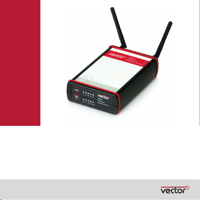
VN8810
Wireless Interface for CAN/LIN/K‐Line and DoIP
Version 1.0
English / Deutsch
Page 2
ENGLISH Quick Start Guide VN8810
1ENGLISH
1.1 Installation
Please use the drivers from the included VectorDriver Disk.
1. Execute Vect or Driver Setup from the autostart menu or directly from
\Drivers\Setup.exe before the device is connected to the PC via USB.
If you have already connected the device to the PC, the W indows found new Hardware
wizard appears. Close this wizard and then execute the driver setup.
2. Finish the driver installation with the setup.
3. If the device has been properly installed, the device can be connected to the PC via USB.
4. Power-up the device by supplying external voltage (e.g. with an appropriate cable offered by
Vector). The device is ready for operation now.
5. In order to change the default settings of the channel assignment between the device and an
application, the configuration tool Vector Hardware (Config) (W indows | Start | Settings |
Control Panel) has to be used.
1.2 Further Information
Note: Further information on the VN8810 interface can be found in the manual on the driver
CD in \Documentation.
1.3 Accessories
Note: Further information on the available accessories can be found in the separate
accessories m anual on the driver CD in \Documentation\Accessories.
-2- Version 1 .0 © Vector Informatik GmbH
Page 3
Quick Start Guide VN8810 ENGLISH
1.4 Device Front Side
1.4.1 LEDs
P1...P5
CAN
K-Line / LIN
ETH
WiFi
Status
Color Description
Green, orange, red Application specific.
Color Description
Green Data fram es have been sent or received correctly.
Orange Error frames have been sent or received.
Red Bus off.
Off No data traffic.
Color Description
Green Data fram es have been sent or received correctly.
Orange Data traffic with at least one error.
Red Error.
Off No data traffic.
Color Description
Green, orange, red Application specific information on link status and activity.
Color Description
Green, orange, red Application specific information on link status and activity.
Color Description
Green Device is ready for operation/running measurem ent.
Orange Initializing or updating software. Please wait.
Red Error. Device not working.
Off Deviceoff.
Flashing frequency depends on the data traffic.
Flashing frequency depends on the data traffic.
© VectorInformatikGmbH Version1.0 -3-
Page 4

ENGLISH Quick Start Guide VN8810
1.4.2 Key Pads
Description > Start/Stop
Starts or stops measurement.
> Multi purpose
Application specific multi purpose key pad.
1.5 Device Back Side
1.5.1 ODU Connector
1.5.2 Switchable CAN High-Speed Termination
CANterm At the back side, the network interface has a CANterm Selector that can be used to disable or
Pin Assignment Pin Assignment
1 Ethernet TX (-) 12 Reserved
2 Reserved 13 Reserved
3 Reserved 14 Ethernet RX (-)
4 DoIP Act. Line 15 Ethernet TX (+)
5 Chassis G ND 16 Not connected
6 Voltage Plus 17 Chassis GND
7 CAN GND 18 Voltage Plus
8 CAN High 19 CAN Low
9LINGND 20K-Line
10 Vbat LIN 21 Not connected
11 Not connected 22 Ethernet RX (+)
2
3
161321
4
17
5
6
enable the term ination for CAN High-Speed. By default, CANterm is enabled:
1
15
18
798
14
22
12
11
20
10
19
with
CANterm
-4- Version 1 .0 © Vector Informatik GmbH
without
CANterm
Page 5

Kurzanleitung VN8810 DEUTSCH
2DEUTSCH
2.1 Installation
Für die Installation verwenden Sie bitte die Treiber auf der beiliegenden Vector Driver Disk.
1. Führen Sie das Vector Driver Setup im Autostartmenü oder direkt von
\Drivers\Setup.exe aus, bevor Sie das G erät über USB anschließen.
Wenn Sie das Gerät bereits angeschlossen haben sollten, erscheint automatisch der Win-
dows Hardwar e Wizard für die Treibersuche. Schließen Sie diesen Wizard und starten Sie
das Treiber-Setup.
2. Führen Sie die Installation mit Hilfe des Setups durch.
3. Nach erfolgreicher Installation kann das Gerät über USB an den PC angeschlossen werden.
4. Nehmen Sie das Gerät in Betrieb, indem Sie eine externe Spannungsversorgung
anschließen (z. B. mit einem geeigneten Kabel von Vector). Das Gerät ist nun betriebsbereit.
5. Zur Änderung der Standardeinstellung von Kanalzuweisungen zwischen dem Gerät und
einer Applikationen muss das Konfigurationstool Vector Hardware (Config) (W indows |
Start | Einstellungen | Systemsteuerung) genutzt werden.
2.2 Weitere Informationen
Hinweis: Detaillierte Informationen zum VN8810 Interface finden Sie im Handbuch auf der
Treiber-CD unter \Documentation.
2.3 Zubehör
Hinweis: Informationen über das verfügbare Zubehör finden Sie im separaten Zube-
hörhandbuch auf der Treiber-CD unter \Documentation\Accessories.
© VectorInformatikGmbH Version1.0 -5-
Page 6

DEUTSCH Kurzanleitung VN8810
2.4 Gerätevorderseite
2.4.1 LEDs
P1...P5
CAN
K-Line / LIN
ETH
WiFi
Status
Farbe Beschreibung
Grün, orange, rot Anwendungsspezifisch.
Farbe Beschreibung
Grün Daten-Frames wurden korrekt gesendet oder em pfangen.
Orange Error-Frames wurden gesendet oder em pfangen.
Rot Bus off.
Aus Kein Datenverkehr.
Farbe Beschreibung
Grün Daten-Frames wurden korrekt gesendet oder em pfangen.
Orange Datenverkehr m it mindestens einem Fehler.
Rot Fehler.
Aus Kein Datenverkehr.
Farbe Beschreibung
Grün, orange, rot Anwendungsspezifische Information über den Link-Status und die Aktivität.
Farbe Beschreibung
Grün, orange, rot Anwendungsspezifische Information über den Link-Status und die Aktivität.
Farbe Beschreibung
Grün Gerät ist betriebsbereit/laufende M essung.
Orange Initialisierung oder Update der Software. Bitte warten.
Rot Fehler. G erät funktioniert nicht.
Aus Gerät aus.
Die Blinkfrequenz ist abhängig vom Datenverkehr.
Die Blinkfrequenz ist abhängig vom Datenverkehr.
-6- Version 1 .0 © Vector Informatik GmbH
Page 7

Kurzanleitung VN8810 DEUTSCH
2.4.2 Tasten
Beschreibung > Start/Stop
Startet oder stoppt eine Messung.
> Mehrzw eck-Taste
Anwendungsspezifische Taste.
2.5 Geräterückseite
2.5.1 ODU-Buchse
2.5.2 Schaltbarer CAN High-Speed Abschlusswiderstand
CANterm Auf der Rückseite steht ein CANterm Selector zur Verfügung, mit dem der Abschlusswider-
Pin Belegung Pin Belegung
1 Ethernet TX (-) 12 Reserviert
2 Reserviert 13 Reserviert
3 Reserviert 14 Ethernet RX (-)
4 DoIP Act. Line 15 Ethernet TX (+)
5 Chassis G ND 16 Nicht verbunden
6 Voltage Plus 17 Chassis GND
7 CAN GND 18 Voltage Plus
8 CAN High 19 CAN Low
9LINGND 20K-Line
10 Vbat LIN 21 Nicht verbunden
11 Nicht verbunden 22 Ethernet RX (+)
stand für CAN High-Speed deaktiviert oder aktiviert werden kann. Standardm äßig ist CANterm
aktiviert.
2
3
161321
4
17
5
6
1
15
18
798
14
22
12
11
20
10
19
mit
CANterm
© VectorInformatikGmbH Version1.0 -7-
ohne
CANterm
Page 8

Get more Information!
Visit our Website for:
>News
> Products
>DemoSoftware
> Support
> Training Classes
> Addresses
www.vector.com
Vector Infor matik GmbH
IngersheimerStraße24
D-70499 Stuttgart
The information and data given in this user manual can be changed without prior notice. No part of this manual may be reproduced in
any formor by any means without the written permission of the publisher, regardless of which method or which instruments,electronic or
mechanical,are used. All technical information,drafts,etc. are liable to law of copyright protection.
Vectorrespects the environment. The user manual is providedon CD to reduce packagingandpaper waste.
© Copyright2015, Vector InformatikGmbH. Printedin Germany.
Art.80453
 Loading...