

Vector VN7640 User Manual
VN7640FlexRay/CAN/LIN/Ethernet Interface
Manual
Version 1.2|English

Imprint
Vector InformatikGmbH
Ingersheimer Straße 24
D-70499 Stuttgart
The information and data given in this user manual can be changed without prior notice. No part of this manual may be reproduced in any
form or by any means without the written permission of the publisher, regar dless of which method or which instruments, electronic or
mechanical, are used. Alltechnicalinformation, drafts, etc. are liable to law of copyright protection.
© Copyright 2018, Vector Informatik GmbH. All rights reserved.

Contents
Contents
1 Introduction 5
1.1 About this User Manual 6
1.1.1 Certification 7
1.1.2 Warranty 7
1.1.3 Registered Trademarks 7
1.2 Important Notes 8
1.2.1 Safety Instructions and Hazard Warnings 8
1.2.1.1 Proper Use and Intended Purpose 8
1.2.1.2 Hazards 9
1.2.1.3 Disclaimer 9
2 Device Description 10
2.1 Scope of Delivery 11
2.2 Introduction 11
2.3 Accessories 13
2.4 Use Cases 13
2.5 Connectors Bus Side 14
2.6 Connectors USBSide 15
2.7 LEDs 19
2.8 Bus Configuration 21
2.9 Replacing Piggybacks 23
2.10 Technical Data 26
3 Getting Started 28
3.1 Driver Installation 29
3.2 Device Configuration 33
3.3 Loop Tests 34
3.3.1 FlexRay 34
3.3.2 CAN 35
4 Vector Hardware Configuration 37
4.1 General Information 38
4.2 Tool Description 39
4.2.1 Introduction 39
4.2.2 Tree View 40
5 Time Synchronization 43
VN7640 Manual Version 1.2 3

Contents
5.1 General Information 44
5.2 Software Sync 46
5.3 Hardware Sync 47
VN7640 Manual Version 1.2 4

1 Introduction
1 Introduction
In this chapter you find the following information:
1.1 About this User Manual 6
1.1.1 Certification 7
1.1.2 Warranty 7
1.1.3 Registered Trademarks 7
1.2 Important Notes 8
1.2.1 Safety Instructions and Hazard Warnings 8
VN7640 Manual Version 1.2 5
1 Introduction
1.1 About this User Manual
Conventions In the two following charts you will find the conventions used in the user manual
regarding utilized spellings and symbols.
Style Utilization
bold Blocks, surface elements, window- and dialog names of the soft-
ware. Accentuation of warnings and advices.
[OK]
File|Save
Microsoft Legally protected proper names and side notes.
Source Code
Hyperlink Hyperlinks and references.
<CTRL>+<S> Notation for shortcuts.
Symbol Utilization
File name and source code.
This symbol calls your attention to warnings.
Push buttons in brackets
Notation for menus and menu entries
Here you can obtain supplemental information.
Here you can find additional information.
Here is an example that has been prepared for you.
Step-by-step instructions provide assistance at these points.
Instructions on editing files are found at these points.
This symbol warns you not to edit the specified file.
VN7640 Manual Version 1.2 6

1.1.1 Certification
1 Introduction
Certified Quality
Management System
Vector Informatik GmbH has ISO 9001:2008 certification. The ISO standard is a globally recognized standard.
1.1.2 Warranty
Restriction
of warranty
We reserve the right to change the contents of the documentation and the software
without notice. Vector Informatik GmbH assumes no liability for correct contents or
damages which are resulted from the usage of the documentation. We are grateful for
references to mistakes or for suggestions for improvement to be able to offer you
even more efficient products in the future.
1.1.3 Registered Trademarks
Registered
trademarks
All trademarks mentioned in this documentation and if necessary third party
registered are absolutely subject to the conditions of each valid label right and the
rights of particular registered proprietor. All trademarks, trade names or company
names are or can be trademarks or registered trademarks of their particular proprietors. All rights which are not expressly allowed are reserved. If an explicit label of
trademarks, which are used in this documentation, fails, should not mean that a name
is free of third party rights.
► Windows, Windows 7, Windows 8.1, Windows 10
are trademarks of the Microsoft Corporation.
VN7640 Manual Version 1.2 7

1.2 Important Notes
1.2.1 Safety Instructions and Hazard Warnings
Caution!
In order to avoid personal injuries and damage to property, you have to read and
understand the following safety instructions and hazard warnings prior to installation and use of this interface. Keep this documentation (manual) always near the
interface.
1.2.1.1 Proper Use and Intended Purpose
Caution!
The interface is designed for analyzing, controlling and otherwise influencing control systems and electronic control units. This includes, inter alia, bus systems like
CAN, LIN, K-Line, MOST, FlexRay, Ethernet, BroadR-Reach and/or ARINC 429.
1 Introduction
The interface may only be operated in a closed state. In particular, printed circuits
must not be visible. The interface may only be operated (i) according to the instructions and descriptions of this manual; (ii) with the electric power supply designed
for the interface, e.g. USB-powered power supply; and (iii) with accessories manufactured or approved by Vector.
The interface is exclusively designed for use by skilled personnel as its operation
may result in serious personal injuries and damage to property. Therefore, only
those persons may operate the interface who (i) have understood the possible
effects of the actions which may be caused by the interface; (ii) are specifically
trained in the handling with the interface, bus systems and the system intended to
be influenced; and (iii) have sufficient experience in using the interface safely.
The knowledge necessary for the operation of the interface can be acquired in
work-shops and internal or external seminars offered by Vector. Additional and
interface specific information, such as „Known Issues“, are available in the „Vector
KnowledgeBase“on Vector´s website at www.vector.com. Please consult the
„Vector KnowledgeBase“for updated information prior to the operation of the interface.
VN7640 Manual Version 1.2 8

1.2.1.2 Hazards
1.2.1.3 Disclaimer
1 Introduction
Caution!
The interface may control and/or otherwise influence the behavior of control systems and electronic control units. Serious hazards for life, body and property may
arise, in particular, without limitation, by interventions in safety relevant systems
(e.g. by deactivating or otherwise manipulating the engine management, steering,
airbag and/or braking system) and/or if the interface is operated in public areas
(e.g. public traffic, airspace). Therefore, you must always ensure that the interface
is used in a safe manner. This includes, inter alia, the ability to put the system in
which the interface is used into a safe state at any time (e.g. by „emergency shutdown“), in particular, without limitation, in the event of errors or hazards.
Comply with all safety standards and public regulations which are relevant for the
operation of the system. Before you operate the system in public areas, it should
be tested on a site which is not accessible to the public and specifically prepared
for performing test drives in order to reduce hazards.
Caution!
Claims based on defects and liability claims against Vector are excluded to the
extent damages or errors are caused by improper use of the interface or use not
according to its intended purpose. The same applies to damages or errors arising
from insufficient training or lack of experience of personnel using the interface.
VN7640 Manual Version 1.2 9

2 Device Description
2 Device Description
In this chapter you find the following information:
2.1 Scope of Delivery 11
2.2 Introduction 11
2.3 Accessories 13
2.4 Use Cases 13
2.5 Connectors Bus Side 14
2.6 Connectors USBSide 15
2.7 LEDs 19
2.8 Bus Configuration 21
2.9 Replacing Piggybacks 23
2.10 Technical Data 26
VN7640 Manual Version 1.2 10
2 Device Description
2.1 Scope of Delivery
Contents The delivery includes:
► VN7640FlexRay/CAN/LIN/Ethernet Interface
► Vector Power Supply 12 V / 1.25 A (part number 05024)
► USB2.0 cable (part number 05011)
2.2 Introduction
About the VN7640 The VN7640 interface is a flexible solution for FlexRay, CAN, LIN, K-Line and J1708
applications. Additionally, different use cases are supported for Ethernet.
Main use cases:
► Remaining bus simulation
► Bus analysis (full bus load, advanced analysis and stimulation features)
► Measurement and calibration via CAN/LIN/FlexRay
► Diagnostics
► ECU flash programming (high performance, sending with minimum delay, out of
spec baud rates, several parallel streams)
► Simple analog/digital IO tasks
Ethernet port based used cases (RJ45 connector):
► Ethernet as interface to calibration devices (xPOD, VX1131, VX1132, ...)
► Ethernet port as interface for DoIP
► Ethernet port as host interface to PC
An Ethernet Use Case Matrix for Vector network interfaces can be found on the
VN7640 page of the Vector homepage.
Figure 1: VN7640FlexRay/CAN/LIN/Ether net Interface
Main features of the VN7640:
► 4x plug-in location for Piggybacks (see section Bus Configuration on page 21)
► Full featured support of
- FlexRay
- CAN (FD)
- LIN
- K-Line
VN7640 Manual Version 1.2 11
2 Device Description
► IO port
- Digital/analog in/out
- DoIP Activation Line
► Trigger-out (via pin 5 of FRpiggyC 1082cap)
► CAPL-On-Board for
- CAN (FD)
- FlexRay
- LIN
- IO
► Ethernet
- IEEE802.3: 100BASE-TX and 1000BASE-T
- BroadR-Reach (100 MBit; physical layer not fully compliant to
Automotive Ethernet / 100BASE-T1)
► Support of customer applications via XL-Driver Library (XL-API)
► Multi-application support (simultaneous operation of different applications on one
channel, e.g. CANoe and CANape)
► High time stamp accuracy
► Time synchronization of multiple devices and with other bus systems (CAN, LIN,
FlexRay, MOST, Ethernet)
- Software time synchronization (typ. 50µs accuracy)
- Hardware time synchronization (1µs accuracy; Binder connector)
► Connection to host PC via USB 2.0 or Ethernet
► LEDs indicating status and activities
► External power supply, galvanically isolated
► Robust Bopla housing
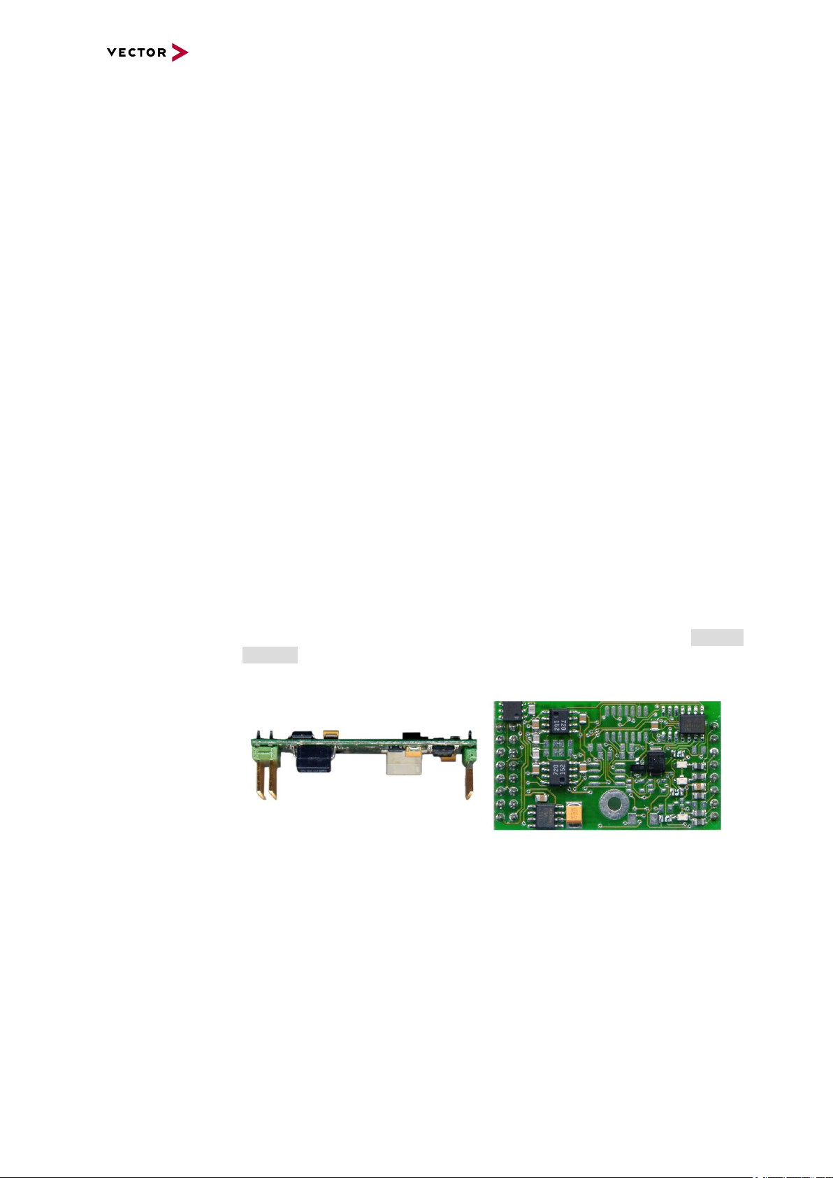
Bus types The bus types CAN, LIN and FlexRay are configurable via exchangeable plug-in
boards (Piggybacks). The supported combinations are described in section Bus Configuration on page 21. A list of compatible Piggybacks can be found in the accessories
manual on the Vector Driver Disk.
Figure 2: Piggyback
VN7640 Manual Version 1.2 12
2.3 Accessories
PC / Notebook
VN7640
USB
IO
LIN (K-Line)
J1708
FlexRay
FRpiggy
CAN FD
CAN/LIN/
J1708piggy
ETH Port
ECU
Activation Line
DoIP
ECU
VX System
xPODs
Data transfer IEEE 802.3
Sync
HW Sync
VNXXXX
Interfaces
PC / Notebook
VN7640
Ethernet
IO
LIN (K-Line)
J1708
FlexRay
FRpiggy
CAN FD
CAN/LIN/
J1708piggy
Sync
HW Sync
VNXXXX
Interfaces
Reference
Information on available accessories can be found in the separate accessories
manual on the Vector Driver Disk in \Documentation\Accessories.
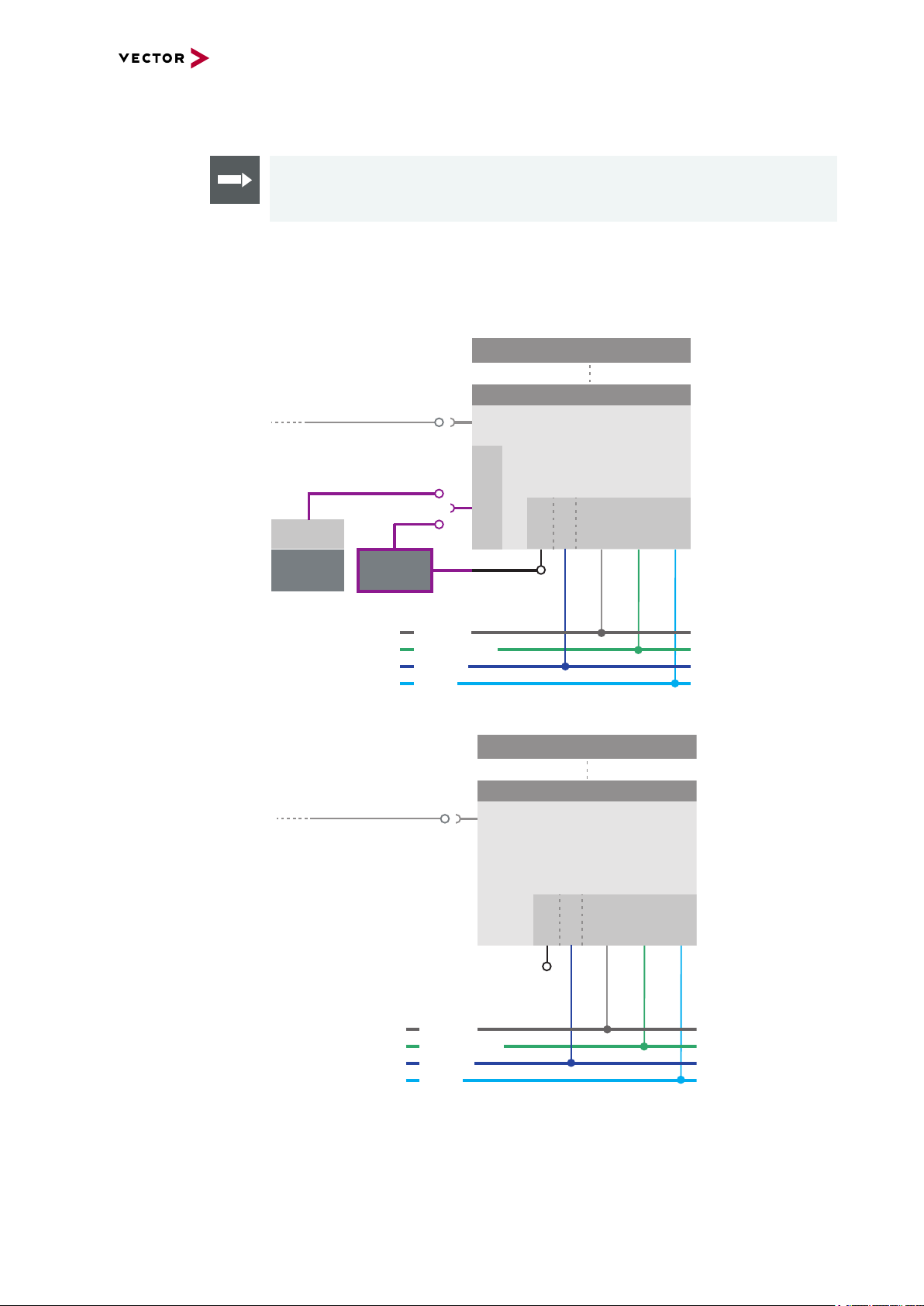
2.4 Use Cases
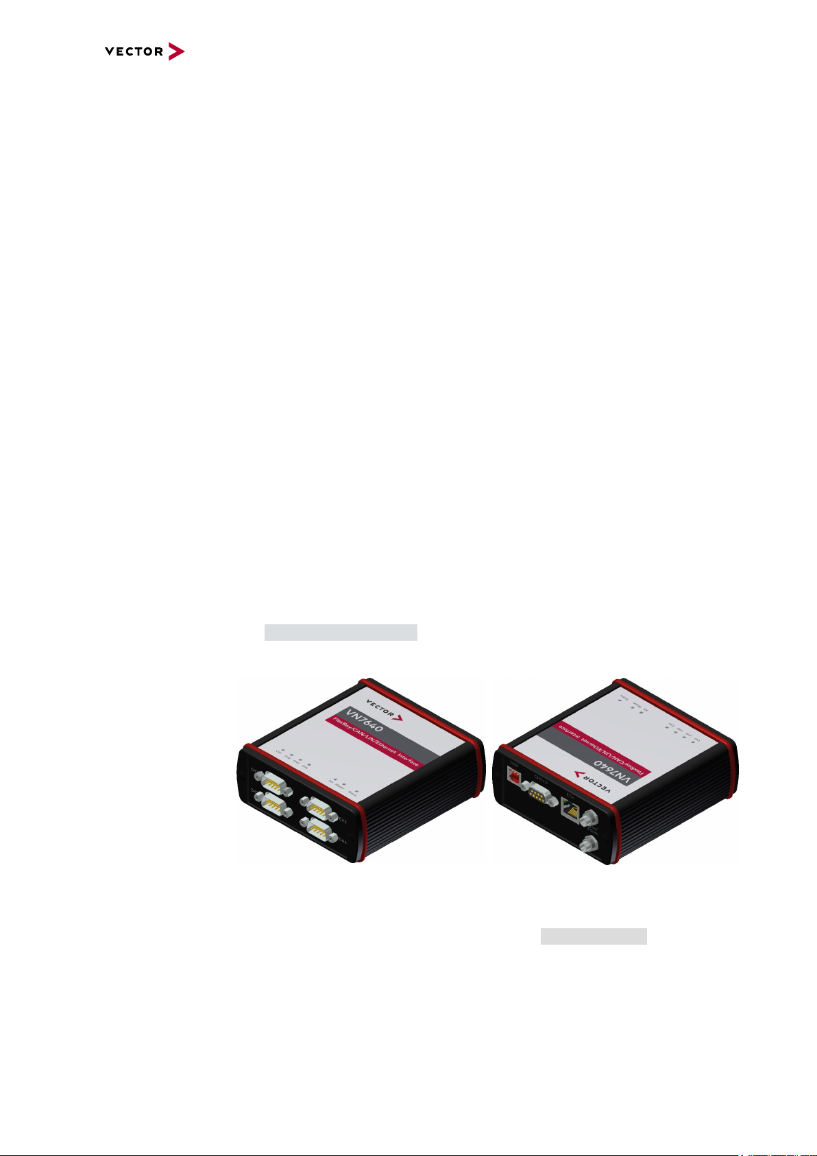
The following picture shows possible use cases of the VN7640.
Host connection via
USB
2 Device Description
Host connection via
Ethernet
Figure 3: Connection via USB
Figure 4: Connection via Ethernet
VN7640 Manual Version 1.2 13
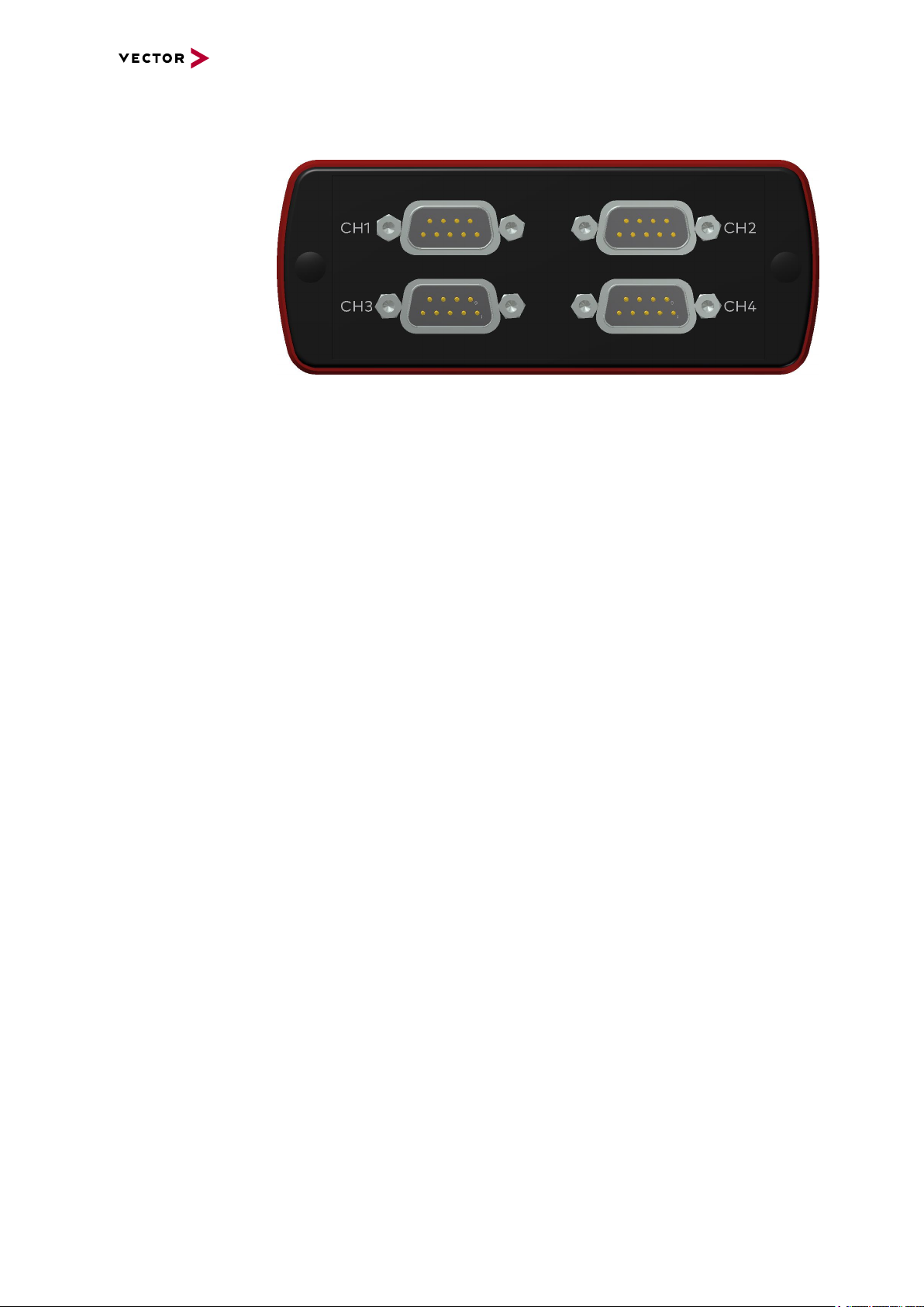
2.5 Connectors Bus Side
Front side
Figure 5: VN7640 with D-SUB9 connectors
► D-SUB9 (CH1...4)
The VN7640 has four D-SUB9 connectors, each assigned to a dedicated Piggyback plug-in location. The pin assignments depend on the inserted Piggybacks. A
list of available Piggybacks and their D-SUB9 pin assignments can be found in the
separate accessories manual on the Vector Driver Disk in
\Documentation\Accessories.
2 Device Description
VN7640 Manual Version 1.2 14
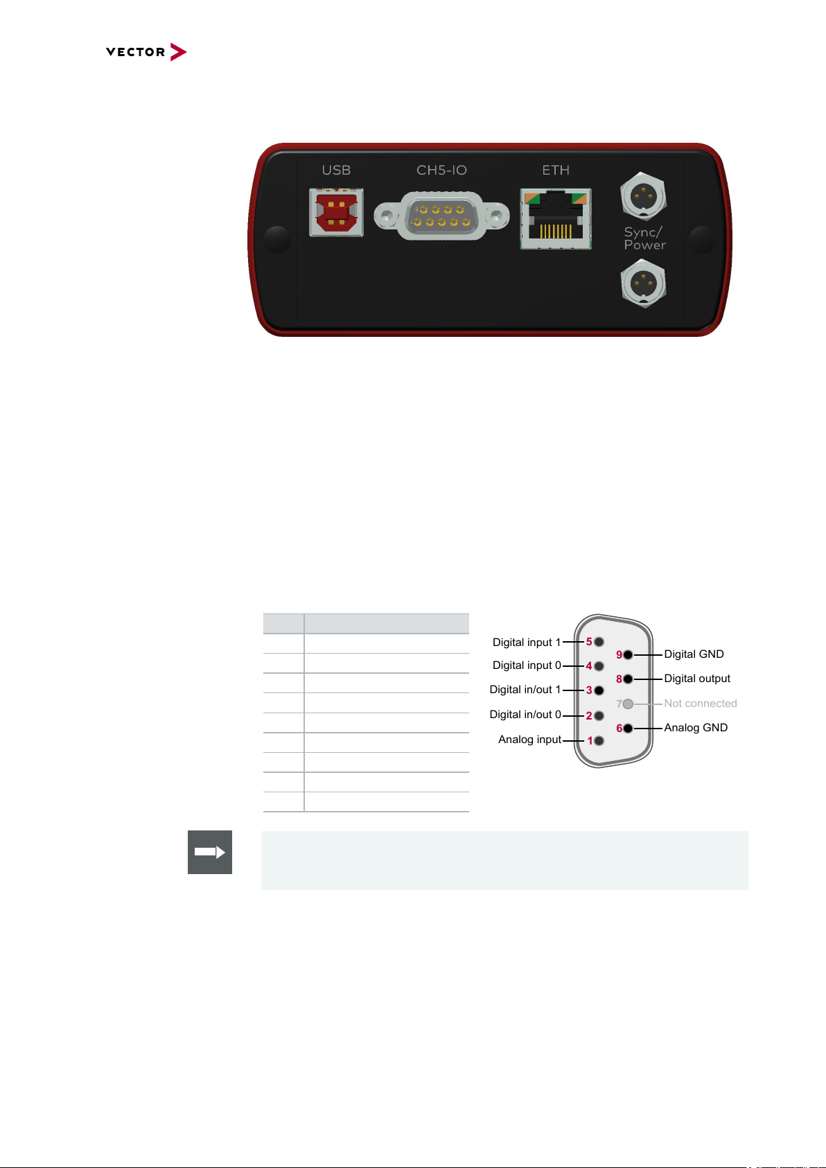
2.6 Connectors USBSide
5
4
3
2
167
8
9
Digital input 1
Not connected
Digital output
Digital GND
Analog GND
Digital input 0
Digital in/out 1
Digital in/out 0
Analog input
Back side
Figure 6: Connectors on the USBside
Device connectors ► USB
Connect your PC and the VN7640 via USB to install and to use the device with
measurement applications (e.g. CANoe, CANalyzer). Use the USB2.0 compliant
cable found in the delivery (USB extension cables may generate faults between
the PC and the device). Connect the device directly to USB at your PC or use a
USB hub.
2 Device Description
► D-SUB9 (CH5)
The VN7640 has a D-SUB9 connector (CH5) for dedicated digital-analog input/output tasks. For DoIP (Diagnostics over Internet Protocol), pin 2 and pin 3 can be
used as DoIP Activation Line according to ISO 13400-3:2011-12.
The pin assignment for CH5 is as follows:
Pin Assignment
1 Analog input
2 Digital input/output 0
3 Digital input/output 1
4 Digital input 0
5 Digital input 1
6 Analog GND
7 Not connected
8 Digital output
9 Digital GND
Reference
Details on the internal interconnection of the input/ouput pins can be found on
the next page.
VN7640 Manual Version 1.2 15
 Loading...