

Page 1

Manual
FlexRay Interface Family
VN3300/VN3600/VN7600
Version 2.0
English
Page 2

A
A
Imprint
Vector Informatik GmbH
Ingersheimer Straße 24
D-70499 Stuttgart
The information and data given in this user manual can be changed without prior notice. No part of this manual may be reproduced in
any form or by any means without the written permission of the publisher, regardless of which method or which instruments, electronic
or mechanical, are used. All technical information, drafts, etc. are liable to law of copyright protection.
© Copyright 2010, Vector Informatik GmbH. Printed in Germany.
ll rights reserved.
rt. 80310
Page 3

Manual Introduction
Table of contents
1 Introduction 3
1.1 About this User Manual 4
1.1.1 Access Help and Conventions 4
1.1.2 Certification 5
1.1.3 Warranty 5
1.1.4 Support 5
1.1.5 Registered Trademarks 5
2 FlexRay Interface Family 7
2.1 Common Features 8
2.2 Synchronization 8
2.3 Trigger 9
2.4 Main Connectors 10
2.5 Technical Data 11
2.6 VN3300 12
2.6.1 Connectors 12
2.7 VN3600 13
2.7.1 Connectors 13
2.7.2 LED Display 14
2.8 VN7600 15
2.8.1 Connectors 15
2.8.2 LED Display 16
3 Hardware installation 17
3.1 General Information 18
3.1.1 VN3300 18
3.1.2 VN3600/VN7600 18
3.2 Replacing Piggybacks 19
3.2.1 VN3300 19
3.2.2 VN3600/VN7600 20
4 Accessories 23
4.1 Piggybacks 24
4.2 Cables 24
4.2.1 FRcable A 24
4.2.2 FRcable AB 25
4.2.3 SYNCcableXL 25
4.3 Miscellaneous 26
4.3.1 FRterm 26
5 Appendix A: Addresses 27
© Vector Informatik GmbH Version 2.0 - I -
Page 4

Page 5

Manual Introduction
1 Introduction
In this chapter you find the following information:
1.1 About this User Manual page 4
Access Help and Conventions
Certification
Warranty
Support
Registered Trademarks
© Vector Informatik GmbH Version 2.0 - 3 -
Page 6
Introduction Manual
1.1 About this User Manual
1.1.1 Access Help and Conventions
The user manual provides you the following access help: To find information
quickly
Conventions In the two following charts you will find the conventions used in the user manual re-
¼ At the beginning of each chapter you will find a summary of the contents,
¼ In the header you can see in which chapter and paragraph you are ((situated)),
¼ In the footer you can see to which version the user manual replies.
garding utilized spellings and symbols.
Style Utilization
bold
Windows Legally protected proper names and side notes.
Source code
Hyperlink Hyperlinks and references.
<STRG>+<S> Notation for shortcuts.
Blocks, surface elements, window- and dialog names of the software. Accentuation of warnings and advices.
[OK] Push buttons in brackets
File | Save Notation for menus and menu entries
File name and source code.
Symbol Utilization
This symbol calls your attention to warnings.
Here you can find additional information.
Here is an example that has been prepared for you.
Step-by-step instructions provide assistance at these points.
Instructions on editing files are found at these points.
This symbol warns you not to edit the specified file.
- 4 - Version 2.0 © Vector Informatik GmbH
Page 7

Manual Introduction
1.1.2 Certification
Certified Quality
Management System
Vector Informatik GmbH has ISO 9001:2008 certification. The ISO standard is a globally recognized standard.
1.1.3 Warranty
Restriction
of warranty
We reserve the right to change the contents of the documentation and the software
without notice. Vector Informatik GmbH assumes no liability for correct contents or
damages which are resulted from the usage of the user manual. We are grateful for
references to mistakes or for suggestions for improvement to be able to offer you
even more efficient products in the future.
1.1.4 Support
You need support? You can get through to our support at the phone number
+49 711 80670-200 or by fax
+49 711 80670-111
E-Mail: support@vector.com
1.1.5 Registered Trademarks
Registered
trademarks
All trademarks mentioned in this user manual and if necessary third party registered
are absolutely subject to the conditions of each valid label right and the rights of particular registered proprietor. All trademarks, trade names or company names are or
can be trademarks or registered trademarks of their particular proprieto rs. All rights
which are not expressly allowed, are reserved. If an explicit label of trademarks,
which are used in this user manual, fails, should not mean that a name is free of third
party rights.
¼ Windows, Windows XP, Windows Vista, Windows 7 are trademarks of the Micro-
soft Corporation.
© Vector Informatik GmbH Version 2.0 - 5 -
Page 8

Page 9

Manual FlexRay Interface Family
2 FlexRay Interface Family
In this chapter you find the following information:
2.1 Common Features page 8
2.2 Synchronization page 8
2.3 Trigger page 9
2.4 Main Connectors page 10
2.5 Technical Data page 11
2.6 VN3300 page 12
Connectors
2.7 VN3600 page 13
Connectors
LED Display
2.8 VN7600 page 15
Connectors
LED Display
© Vector Informatik GmbH Version 2.0 - 7 -
Page 10

FlexRay Interface Family Manual
2.1 Common Features
FlexRay Interfaces
for PCI and USB
Further properties
Configuration The Vector Hardware Configuration tool (see Start | Settings | Control Panel |
The FlexRay Interface Family offers a future-proofed and powerful solution for development, simulation, test, measurement or calibration of FlexRay networks through an
FPGA-based FlexRay communication controller.
The devices have a fast 32 bit microcontroller (312 MHz) and allow, besides the ability of transmitting and receiving of data and null frames, the detection of invalid
frames on the bus. Future features can also be added in the field by FPGA updates.
¼ Simulation of comprehensive networks due to the 2 MB transmission
¼ Time synchronization of multiple devices of the FlexRay or XL Interface Family
¼ Cycle multiplexing
¼ Trigger input and output
¼ Supports 254 byte maximum payload
¼ In-cycle response
¼ Hardware-based incrementing of a payload area
¼ Startup monitoring
¼ FlexRay-Driver-Library for creating own applications
Vector Hardware) enables the configuration of the devices. Further details can be
found in the installation instructions.
Bus types The connection of the devices to the FlexRay bus is done by transceivers that are
available as plug-in boards (Piggybacks). A list of available FRpiggies can be found in
chapter Piggyback on page 24.
2.2 Synchronization
Software/hardware
synchronization
Functionality of
hardware
synchronization
The time stamps, which are created during a measurement by devices of the FlexRay
Interface and XL Family, can be synchronized by software or hardware.
The software synchronization is driver-based and available for all applications without
any restrictions. The software synchronization can be enabled in Vector Hard ware
Config | General information | Settings | Software time synchronization. The
accuracy of the time stamp correction depends on the device and is typically 50 µs.
The hardware synchronization of maximum four devices is done through the SYNCcable (see description below) and has to be supported by the application. The accuracy of the time stamp correction depends on the application and is typically 1 µs.
The devices to be synchronized must be interconnected by a party line (two-wire bus;
signals: SYNC and GND).
At each high-low edge of the sync line the Vector device generates a time stamp that
is provided to the application via the driver. This allows the application to synchronize
the time stamps of different devices to a common time base.
The synchronization edges can be generated by the devices of the FlexRay Family or
other devices of the XL Family.
- 8 - Version 2.0 © Vector Informatik GmbH
Page 11
Manual FlexRay Interface Family
Info: The time synchronization must be supported by the application. For further infor-
mation please refer to the relevant manual. Please note that the time synchronization
of the driver must be disabled, if multiple devices of the FlexRay and XL Family are
being operated on a PC and interconnected via the synchronization line (see Vector
Hardware Config | General information | Settings | Software time synchronization).
Synchronization by
Binder connector
Synchronization by
sync connector
2.3 Trigger
Trigger inputs
and outputs
The devices have a time synchronization signal at pin 2 of the 3-pin Binder connector.
You can connect devices of the Vector FlexRay or XL Family with the SYNCcableXL
(see chapter SYNCcableXL on page 25) to this pin.
The synchronization of multiple VN3300 can be done either through the Binder connector outside the PC housing or by the internal sync connector. The internal sync
connector is a 10-pin connector (90° offset) and available next to the Piggyba ck slot.
The synchronization is done through a ribbon cable with a 10-pin standa rd socket.
Info: Synchronization through the Binder and sync connector at the same time is not
possible.
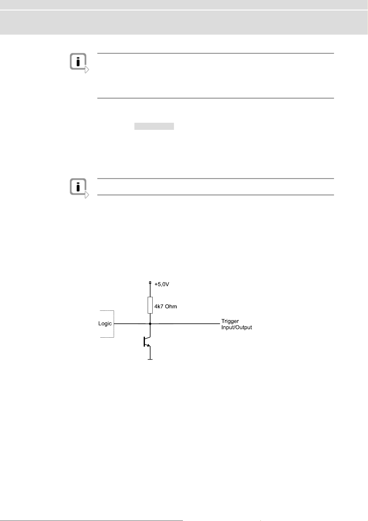
The devices of the FlexRay Family have a trigger connector each with four lines (see
the according pin assignment). Pin 2 is an independent trigger input and pin 3 an
independent trigger output. Pin 4 and 5 can be used as trigger input as well as trigger
output. The configuration of the triggers and their actions is set in the application
(e. g. CANoe). The following picture depicts the intern
al circuit of pin 4 and 5.
Pin 4 and 5 used for
r input
trigge on the trigge
© Vector Informatik GmbH Version 2.0 - 9 -
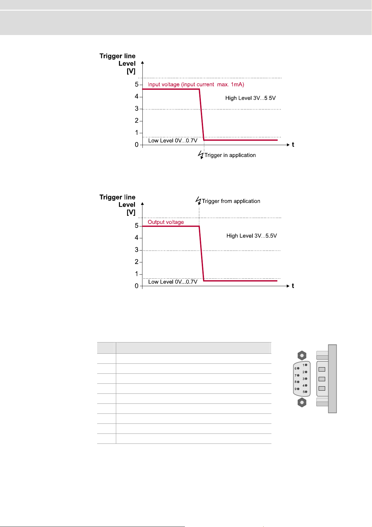
If pin 4 and 5 are being used for trigger input, the trigger will be fired by a falling e
r line. The trigger is processed inside the application. If the trigger i
eing wired, the internal 4.7 kOhm resistor must be kept in mind.
b
dge
nput is
Page 12
FlexRay Interface Family Manual
in 4 and 5 used for
P If
trigger output
pin 4 and 5 are being used for trigger output, the trigger of the application releases
a falling edge on the trigger line. By using external pull up resistors, the maximum
allowed load is 5 mA.
2.4 Main Connectors
D-SUB9 connector The devices have a FlexRay connector (channel A and B) which is available as
D-SUB9 (male). The pin assignment is as follows:
Pin Assignment
1 N.C.
2 BM Channel A
3 GND
4 BM Channel B
5 Shield
6 N.C.
7 BP Channel A
8 BP Channel B
9 VB+
- 10 - Version 2.0 © Vector Informatik GmbH
Page 13
Manual FlexRay Interface Family
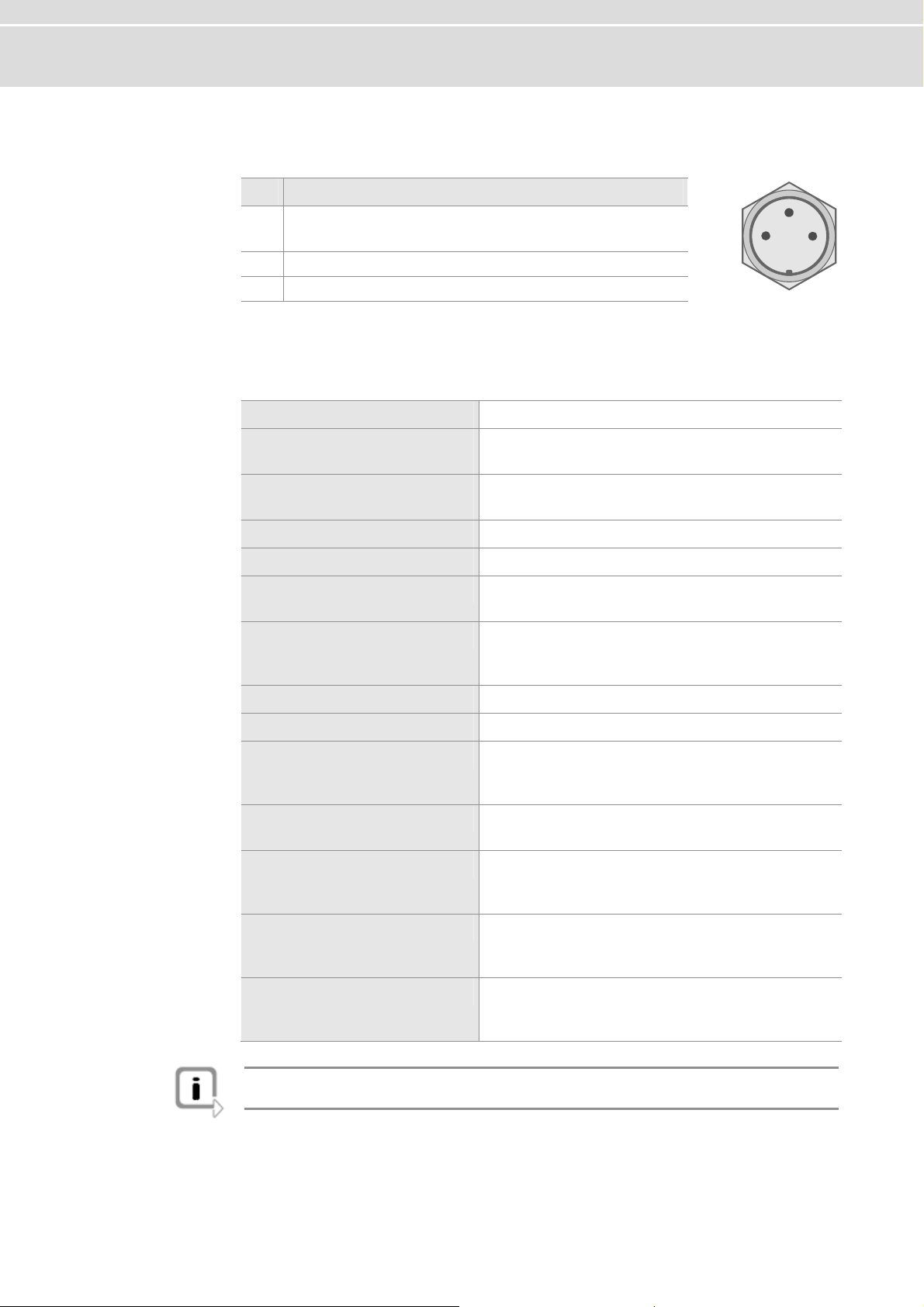
Binder connector T i f the Binder connector is as follows: he p n assignment o
Pin Assignment
1 : N.C.
VN3300
VN3600/7600 : power
2 zation line (low active) Synchroni
3 pply and sync line GND of voltage su
supply
2
3
1
2.5 Technical D taa
Intel PXA270 (312 MHz)
Microcontroller
FlexRay communication-
controller (analysis)
FlexRay communication-
controller (startup)
Memory for data transmission
FlexRay cluster
FlexRay channels
CAN channels
Maximum payload
Transceiver
PC interface
Temperature range
External power supply
Dimensions (LxWxH)
Operating system
Bosch E-Ray
(Altera Cyclone II EP2C70)
Fujitsu MB88121B
2 MB
1
2 (Channel A & B of a cluster)
1x D-SUB9 connector (male)
VN3300: 0
VN3600: 0
VN7600: 3, each with 1x D-SUB9 (male)
254 Bytes
See plug-in board (FRpiggy)
VN3300: PCI
VN3600: USB 2.0
VN7600: USB 2.0
Operation: -0..+55 °C
Storage : -40..+85 °C
VN3300: 5 V, typical 3.2 W
VN3600: 5 V..50 V (startup min. 8 V), typical 3 W
VN7600: 5 V..50 V (startup min. 8 V), typical 4.5 W
VN3300: 167 x 107 x 15 mm
VN3600: 151 x 110 x 35 mm
VN7600: 151 x 110 x 45 mm
Windows XP, 32 bit (SP3)
Windows Vista, 32 bit (SP1)
Windows 7, 32 bit or 64 bit
Info: The temperature of single housing parts may be higher than the temperature of
the environment, even if the device is correctly operated.
© Vector Informatik GmbH Version 2.0 - 11 -
Page 14
FlexRay Interface Family Manual
2.6 VN3300
6.1 Connectors
2.
VN3300 (PCI) The V ors:
N3300 has the following connect
1x channel A und channel B)
¼ D-SUB9 connector for FlexRay (
1x between other devices of the FlexRay
¼ Binder connector for synchronization
and XL Famil
¼ 1x Internal sync connector
¼ 1x Intern
y (3-pin)
al trigger connector (10-pin)
Main connectors
The pin assignment of the main connectors can be found in section Main Connectors
on page 10.
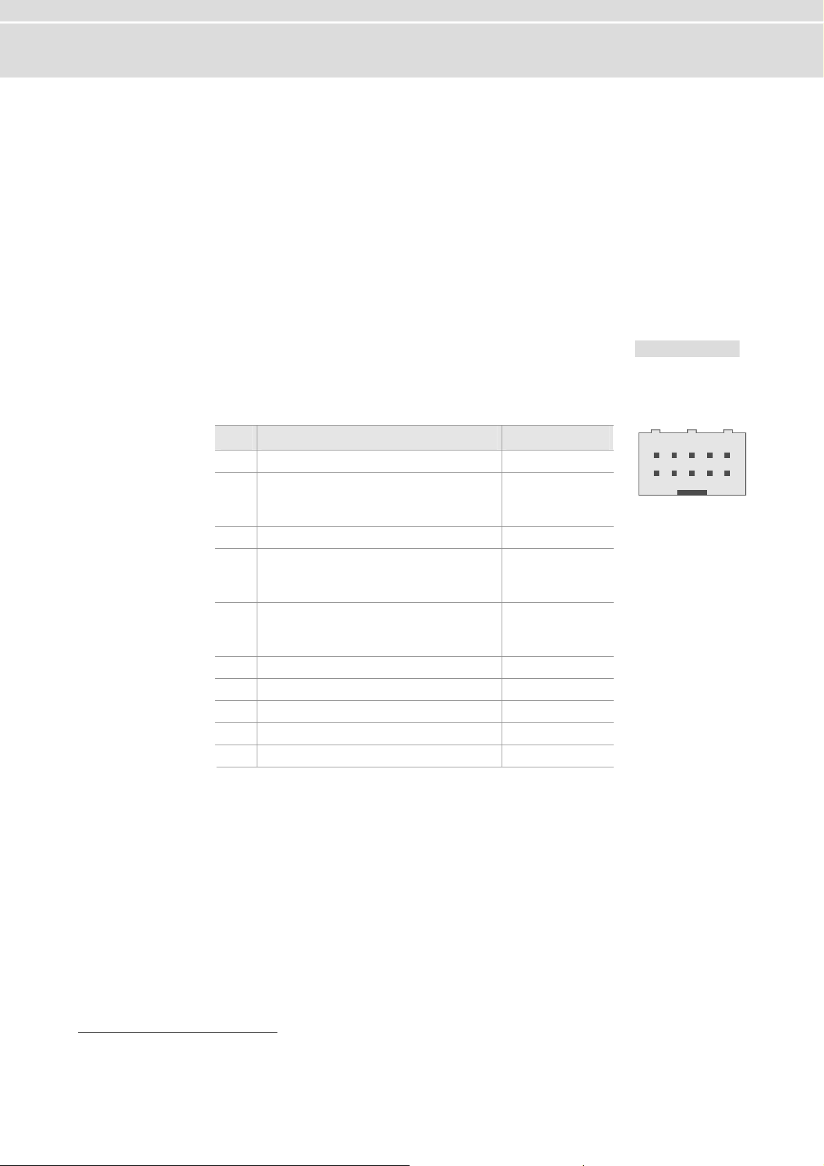
Trigger connector he pin e
The following table shows t assignment of the 10-pin trigg r connector.
Pin Assignment Software Port1
5 V (max. 35 mA) - 1 Output voltage
Trigger In (TTL 5 V, low ac
2
: 3.0
V
V
Hmin
Lmin
V / V
: 0.0 V / V V
Hmax
Lmax
t
ive)
: 5.5 V
: 0.7
3
TL 5 V, low a3 Trigger Out (T ctive) 0
Trigger In/
4
V
Hmin
V
Lmin
Trigger In/Out (5 V, low ac
5
V
Hmin
V
Lmin
Out (5 V, low acti
: 3.
0 V / V
: 0.0 V / V
Hmax
Lmax
: 5.5
: 0.7
ve)
V
V
tive)
: 3.0 V
: V
/ V
0.0 V / V
Hmax
Lmax
: 5.5
: 0.7
V
1
2
6 Reserved. Do not connect. 7 Reserved. Do not connect. 8 GND 9 Reserved. Do not connect. -
10 Reserved. Do not connect. -
246810
13579
Connecting cable A fitting cable for the trigger conne
IDSD-05-S-xxxx (xxxx means further
ctor is available from Samtec named
cable details which depend on the application).
1
Used by Vector software, e. g. in CANoe
- 12 - Version 2.0 © Vector Informatik GmbH
Page 15
Manual FlexRay Interface Family
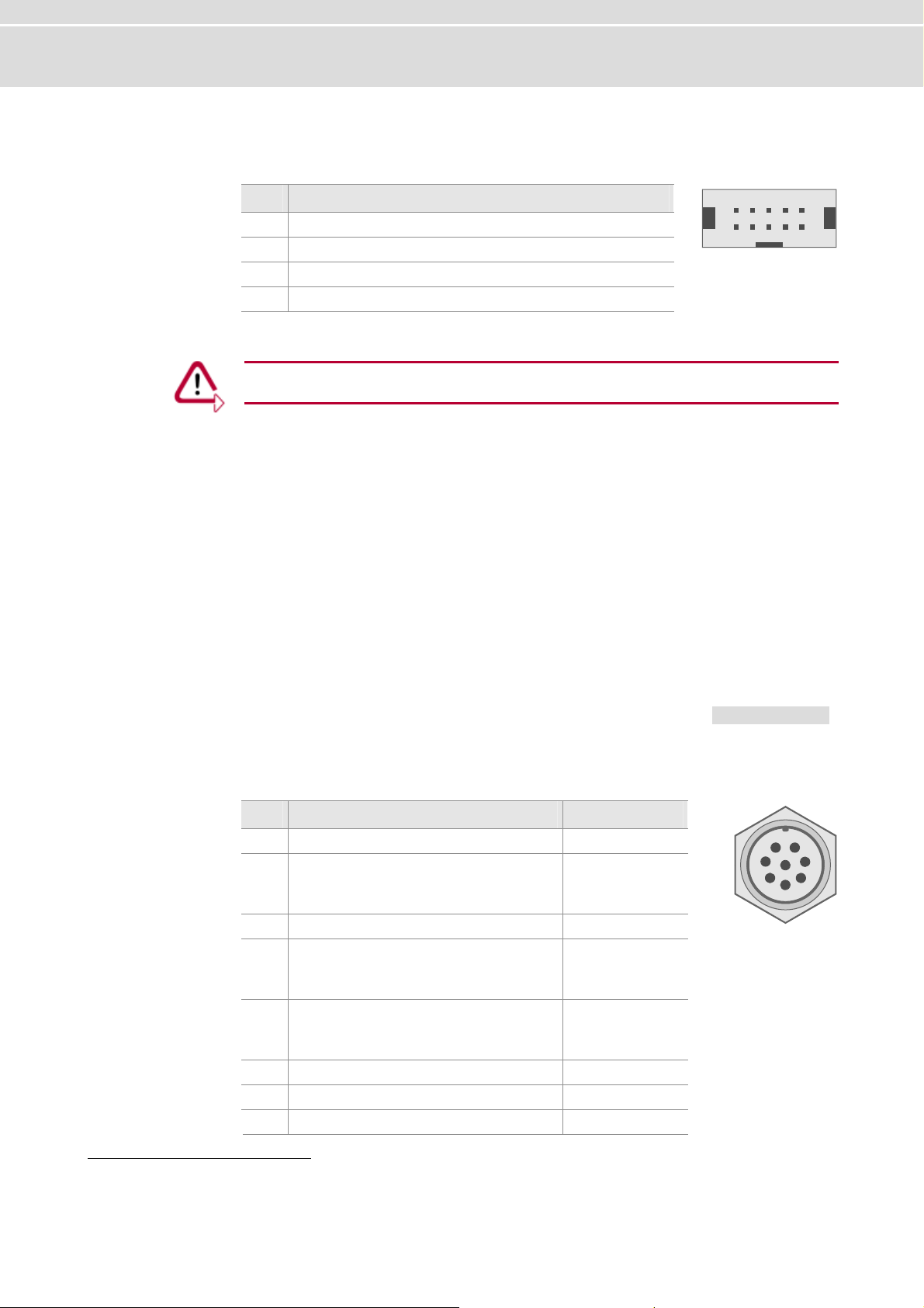
Sync connector
The following table shows the pin assignment of the 10-pin sync conne ctor
(90° offset).
Pin Assignment
1 GND
2..8 Reserved. Do not connect.
9 Synchronization line (low active)
10 Output voltage 5 V (output, 35 mA)
Caution: In order to avoid electrical damages on the device, the trigger and sync
connector must not be connected at any time!
2.7
VN3600
2.7.1 Connectors
VN3600 (USB) The
¼ 1x USB 2.0 connector
¼ 1x D-SUB9 connector for FlexRay (channel A und ch
¼ 1x Binder connector for trigger (8-pin)
¼ 2x Binder connector for power supply and synchronization between other device
246810
13579
VN3600 has the following connectors:
annel B)
s
of the FlexRay and XL Family (3-pin)
Main connectors
The pin assignment of the main connector
s can be found in section Main Connectors
on page 10.
Binder connector The following table shows the pin assignment of the 8-pin Binder connector:
2
Used by Vector software, e. g. in CANoe
Pin Assignment Software Port
1 Output voltage 5 V (max. 35 mA) -
Trigger In (TTL 5 V, low active)
2
: 3.0 V / V
V
Hmin
V : 0.0 V / V : 0.7 V
Lmin Lmax
3 Trigger Out (TTL 5 V, low active
Trigger In/Out (5 V, low active)
4
: 3.0 V / V
V
Hmin
V : 0.0 V / V : 0.7 V
Lmin Lmax
Trigger In/Out (5 V, low active)
5
: 3.0 V / V
V
Hmin
V : 0.0 V / V : 0.7 V
Lmin Lmax
6 Reserved. Do not connect. 7 e - Reserved. Do not conn ct.
8 GND -
: 5.5 V
Hmax
: 5.5 V
Hmax
: 5.5 V
Hmax
) 0
3
1
2
2
6
7
1
8
2
5
3
4
© Vector Informatik GmbH Version 2.0 - 13 -
Page 16

FlexRay Interface Family Manual
2.7.2 LED Display
lexRay
F
A, B and Syn
Rx, Tx,
sync and power
c
T VN has four LEDs with the following meanings:
he 3600
¼ l
FLexRay A
ig d or transmitted on channel A.
hts up, when data is receive
¼ l
F exRay B
Lights up, when data is received or transmitted on channel B.
¼ Sync
LED for both FlexRay channels. Displays the state of the CC:
- Off : Offline.
- Green : Synchronized.
- Orange : Not synchronized.
- Red : Error.
¼ Power
Displays the state of operation:
- Red : Error, the device is not ready for operation.
- Green : The device is ready for operation.
- Orange (blinking) : An automatic FPGA update is executed.
The first hardware revision of VN3600 has six LEDs with the following meanings:
¼ Rx
Lights up, when data is received.
LED for both FlexRay channels available.
¼ Tx
Lights up, when data is transmitted.
LED for both FlexRay channels available.
¼ Sync
LED for both FlexRay channels. Displays the state of the CC:
- Off : Offline.
- Green : Synchronized.
- Orange : Not synchronized.
- Red : Error.
¼ Power
Displays the state of operation:
- Red : Error, the device is not ready for operation.
- Green : The device is ready for operation.
- Orange (blinking) : An automatic FPGA update is executed.
- 14 - Version 2.0 © Vector Informatik GmbH
Page 17
Manual FlexRay Interface Family
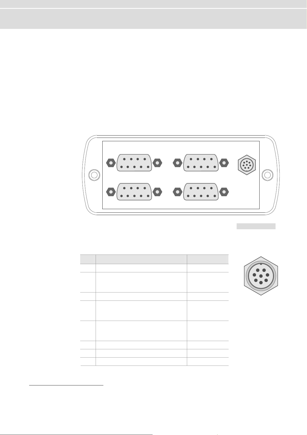
2.8 VN7600
2.8.1
VN760 he 7600
Connectors
0 (USB) T VN has the following connectors:
¼ 1x USB 2.0 connector
¼ x hannel A und channel B)
1 D-SUB9 connector for FlexRay (c
¼ x
3 D-SUB9 connector for CAN
¼ 1x Binder connector for trigger (8-pin)
¼ 2x Binder connector for power supply and synchronization between other devices
of the FlexRay and XL Family (3-pin)
Alignment
of the connectors
FlexRay CAN 1
CAN 2 CAN 3
Trigger
Main connectors
The pin assignment of the main connectors can be found in section Main Connectors
on page 10.
Binder connector T
he following table shows the pin assignment of the 8-pin Binder conne
Pin Software Port3 Assignment
1 Output voltage 5 V (max. 35 mA) -
Trigger In (TTL 5 V, low active)
2
V : 3.0 V / V : 5.5 V
Hmin Hmax
V
: 0.0 V / V
Lmin
3 Trigger Out (TTL 5 V, low active) 0
Trigger In/Out (5 V, low active)
: 3.0 V / V
V
Hmin
: 0.0 V / V
V
Lmin
Trigger In/Out (5 V, low active)
5
: 3.0 V / V
V
Hmin
0.0 V / V
:
V
Lmin
6 Reserved. Do not connect. 7 Reserved. Do not connect. 8 GND -
3
Used by Vector software, e. g. in CANoe
: 0.7 V
Lmax
: 5.5 V
Hmax
: 0.7 V
Lmax
: 5.5 V
Hmax
: 0.7 V
Lmax
3
1 4
2
ctor:
6
7
1
8
2
5
3
4
© Vector Informatik GmbH Version 2.0 - 15 -
Page 18

FlexRay Interface Family
D-SUB9 connector The VN7600 has three CAN channels through D-SUB9 connectors (male). The con-
.8.2 LED Display
2
nection vers, which are available as plug-in boards
(Piggyba CAN channel depends on the inserted CANpiggy. d in the accessories manual on the Driver
Dis : \ ccessories df
to the CAN bus is done by transcei
cks). The pin assignment of a
Further information can be foun
k Documentation\ XL_Family_A .p
Manual
lexRay
F
, B and Sync
A
T VN llowing meanings:
he 7600 has four LEDs with the fo
¼ Fl
exRay A
Lig c r transmitted on cha nnel A.
hts up, when data is re eived o
¼ l
F exRay B
Lights u nsmitted on channel B.
¼ Sy
LED for both
- Off : Offline.
- Green : Synchronized.
- Orange : Not synchronized.
- Red : Error.
¼ d 3 CAN 1, 2 an
Lights up, when data is received or transmitted.
¼ Power
Displays the state of operation:
- Red : Error, the device is not ready for operatio
- Gree
- Orange (blinking) : An automatic FPGA update is executed.
p, when data is received or tra
nc
FlexRay channels available, which di lays the state of the CC:
n : The device is ready for operation.
sp
n.
- 16 - Version 2.0 © Vector Informatik GmbH
Page 19

Manual Hardware installation
3 Hardware
In this chapter you find the following information:
3.1 General Information page 18
VN3300
VN3600/VN7600
3.2 Replacing Piggybacks page 19
VN3300
VN3600/VN7600
installation
© Vector Informatik GmbH Version 2.0 - 17 -
Page 20

Hardware installation Manual
3.1 General Information
3.1.1 VN3300
Caution: Turn off the main power supply and disconnect your computer’s power cord.
Otherwise systems using an ATX power supply unit with soft power off may still be
slot.
Caution: Do not force the VN3300 into the slot. Make sure that the connectors of the
card’s PCI connector are aligned with the bus connector on the motherboard before
you insert the card into the slot. If it does not fit properly, gently remove it and try
again.
Info: Please observe all safety precautions prescribed by your PC manufacturer for
card installation!
serted into the powering the PCI slot. This can damage your PCI card when it is in
Info: Do not touch the bottom and the topside of the PCBs (VN3300 main board and
Piggybacks).
.1.2
3 VN3600/VN7600
1. Turn off the computer and all peripheral devices.
2. Unplug the power cord from the wall outlet.
3. Touch a metal plate on your computer to ground yourself to discharge any static
electricity.
4. Remove
5. Align the VN3300 with the PCI slot and press the gently but firmly into the slot.
6. Replace the computer cover.
7 lu r cord.
. P g in the powe
1. Co wer supply.
2. lu e to any free USB2.0 port.
P g the VN3600/VN7600 with the USB cabl
the computer cover and the metal brackets from an unused slot.
nnect the VN3600/VN7600 to the po
- 18 - Version 2.0 © Vector Informatik GmbH
Page 21

Manual Hardware installation
3.2 Replacing
3.2.1
VN3300
VN3300
Piggybacks
1. Turn off the computer and all peripheral devices.
2.
Unplug the power cord from the wall outlet.
3. Touch a metal plate on your computer to ground yours
static electricity.
4. Remove the computer cover and unplug the VN3300.
Info: The Piggyback is fixed with a screw.
5. Detach the screw with the screw prot
6. Plug in the alternative FRpiggy.
Internal
Sync Connector
ection and remove the Piggy carefully.
Internal
Trigger Connector
elf and to discharge any
FlexRay
D-SUB9
FRpiggy
Binder
Connector
(Sync)
Info: The connectors must fit and must not be displaced laterally.
7. The FRpiggy has to be fixed again with the screw and the screw protection.
8. Firmly insert the card into the selected slot. Push down to ensure the card is fully
seated.
9. Replace the computer cover.
10. Plug in the power cord.
© Vector Informatik GmbH Version 2.0 - 19 -
Page 22

Hardware installation Manual
3.2.2 VN3600/VN7600
1. First, loosen the VN3600/VN7600 housing screws on the side with the D-SUB9
connector. This requires removing the two black decorative caps. Then carefully
pull the PC-board out of the housing.
2. The FRpiggy is fastened by a screw and retainer. Please loosen the appropriate
screw including the retainer and carefully remove the FRpiggy from the mounting
location.
3. Insert the replacement FRpiggy. When doing this please make sure that the connectors are not laterally offset.
4. Secure the new FRpiggy with the appropriate screw and retainer.
5. Place the VN3600/VN7600 main board back in the housing verifying that it is
inserted properly. This operation involves placing the housing on a table with its
back side (side with the bar code) facing upward. Then the main board with the
FRpiggy is inserted into the upper guide rails with the VN3600/VN7600 facing
upward.
6. It should be possible to slide the main board in the housing up to a few millimeters from the end without forcing it in. Close the housing by applying light pressure, and then secure it with the appropriate screw fasteners. The screws should
be secure but not excessively tight.
VN3600
7. Please also attach the two black decorative caps.
- 20 - Version 2.0 © Vector Informatik GmbH
Page 23

Manual Hardware installation
Info: The replacing of CANpiggies is identical to FRpiggy.
VN7600
© Vector Informatik GmbH Version 2.0 - 21 -
Page 24

Page 25

Manual Accessories
4 Accessorie
In this chapter you find the following information:
4.1 Piggybacks page 24
4.2 Cables page 24
FRcable A
FRcable AB
SYNCcableXL
4.3 Miscellaneous page 26
FRterm
s
© Vector Informatik GmbH Version 2.0 - 23 -
Page 26

Accessories Manual
4.1 Piggybacks
General information es
Availability The following FRpiggies are available:
The bus drivers are located on a separate plug-in board (FRpiggy). This guarante
the FlexRay Interface to be flexible for future applications. If other bus driver
established in the future, e. g. with Bus Guardian, only the FRpiggy has to be replaced.
Piggybacks are used in:
¼ VN3300
¼ VN3600
¼ VN7600
Piggy Bus Transceiver Eigenschaft
FRpiggy 1080 FlexRay TJA1080 Channel A and B on one plug-in board.
FRpiggy 1080mag FlexRay TJA1080 Channel A and B on one plug-in board.
Magnetically decoupled.
s become
4.2 Cables
4.2.1 FRcable A
Cable setup
Type
Length
Connectors
Properties
Cable for connection of a FlexRay Interface to the FlexRay bus
(Channel A).
1m
Both sides with D-SUB9 connectors (female).
Provides Channel A at the FlexRay Interface.
- 24 - Version 2.0 © Vector Informatik GmbH
Page 27

Manual Accessories
2
4.2.2 FRcable AB
Cable setup
Type
Length
Connectors
Properties
Cable for connection of a FlexRay Interface to the FlexRay bus
(Channel A and B).
1m
Three D-SUB9 connectors (female).
Provides Channel A and B at the FlexRay Interface. The pin
assignment of both single ended connectors is identical and
suitable for replacement of an existing FlexCard configuration.
4.2.3 SYNCcableXL
Cable setup
Type
Length
Connectors
1
Connection cable for time synchronization at SyncBox,
CANcaseXL/log, CANboardXL, and VN3300/VN3600/VN7600.
2m
Both ends with 3-pin Binder connector (female) type 711.
m
2
3
22
11
33
Sync
+12V
GND
© Vector Informatik GmbH Version 2.0 - 25 -
Page 28

Accessories
Manual
4.3 Mis
cellaneous
4.3.1 FRterm
Adapter setup
Type
Connectors
Properties
FlexRay adapter for one-sided termination of a FlexRay cluster
(Channel A und B). Pin assignment suitable for
VN3300/VN3600/VN7600.
One male and one female D-SUB9 connector.
2x 100 Ohm terminating resistor.
- 26 - Version 2.0 © Vector Informatik GmbH
Page 29

Manual Appendix A: Addresses
5 Appendix A
Vector Informatik GmbH Vector Informatik GmbH
Vector CANtech, Inc. Vector CANtech, Inc.
Vector Japan
Co., Ltd. Vector Japan Co., Ltd.
: Addresses
Ingersheimer Str. 24
70499 Stuttgart
Germany
Phone : +49 711 80670-0
Fax : +49 711 80670-111
info@de.vector.com
http://www.vector.com
Suite 550
39500 Orchard Hill Place
Novi, Mi 48375
USA
Phone : +1 248 449 9290
Fax : +1 248 449 9704
info@us.vector.com
http://www.vector.com
Seafort Square Cent
2-3-12, Higashi-shinagawa, Shinagawa-ku
140-0002 Tokyo
an
Jap
Phone : +81 3 5769 7800
Fax : +81 3 5769 6975
info@jp.vector.com
http://www.vector.com
er Bld. 18F
Vector France SAS
VecScan AB
Vector France SAS
168, Boulevard Camélinat
92240 Mala
France
Phone : +33 1 4231 4000
Fax : +33 1 4231 4009
info@fr.vector.com
http://www.vector.com
VecScan AB
Theres Svenssons Gata 9
4175
5 Göteborg
Sweden
Phone : +46 31 764 7600
Fax : +46 31 764 7619
info@se.vector.com
http://www.vector.com
koff
© Vector Informatik GmbH Version 2.0 - 27 -
Page 30

Appendix A: Addresses
Vector Korea IT Inc. Vector Korea IT Inc.
1406 Mario Tower
222-12 Guro-dong, Guro-gu
Seoul 152-848
Republic of Korea
Phone : +82 2 8070 600
Fax : +82 2 8070 601
info@kr.vector.com
http://www.vector.com
Vector GB Limited Vector GB Limited
Rhodium, Central Boulevard
Blythe Valley Park
Solihull, Birmingham
West Midlands, B90 8AS
United Kingdom
Phone : +44 121 50681-50
Fax : +44 121 50681-66
info@uk.vector.com
http://www.vector.com
Manual
- 28 - Version 2.0 © Vector Informatik GmbH
Page 31

Manual
Installation Instructions
Version 2.6
English
Page 32

A
Imprint
Vector Informatik GmbH
Ingersheimer Straße 24
D-70499 Stuttgart
The information and data given in this user manual can be changed without prior notice. No part of this manual may be reproduced in
any form or by any means without the written permission of the publisher, regardless of which method or which instruments, electronic
or mechanical, are used. All technical information, drafts, etc. are liable to law of copyright protection.
© Copyright 2010, Vector Informatik GmbH. Printed in Germany.
ll rights reserved.
Page 33

Manual Table of contents
Table of contents
1 Introduction 3
1.1 About this User Manual 4
1.1.1 Access Help and Conventions 4
1.1.2 Certification 5
1.1.3 Warranty 5
1.1.4 Support 5
1.1.5 Registered Trademarks 5
2 Notes 7
2.1 Minimum Requirements 8
2.2 Driver Setup 9
2.3 Vector Hardware Configuration 11
2.4 Further Notes 13
2.4.1 Measurement Applications 13
2.4.2 Device Manager 13
2.4.3 Power Manager 13
3 Operating Test and Troubleshooting 15
3.1 Loop Test 16
3.1.1 CAN 16
3.1.2 FlexRay 19
3.1.3 MOST 20
3.2 Checking Installation 21
3.3 Correction of Driver Installation 21
4 Appendix A: Addresses 23
© Vector Informatik GmbH Version 2.6 - I -
Page 34

Page 35

Manual Introduction
1 Introduction
In this chapter you find the following information:
1.1 About this User Manual page 4
Access Help and Conventions
Certification
Warranty
Support
Registered Trademarks
© Vector Informatik GmbH Version 2.6 - 3 -
Page 36

Introduction Manual
1.1 About this User Manual
1.1.1 Access Help and Conventions
The user manual provides you the following access help: To find information
quickly
Conventions In the two following charts you will find the conventions used in the user manual
¼ At the beginning of each chapter you will find a summary of the contents,
¼ In the header you can see in which chapter and paragraph you are ((situated)).
regarding utilized spellings and symbols.
Style Utilization
bold
Windows Legally protected proper names and side notes.
Source code
Hyperlink Hyperlinks and references.
<STRG>+<S> Notation for shortcuts.
Blocks, surface elements, window- and dialog names of the
software. Accentuation of warnings and advices.
[OK] Push buttons in brackets
File | Save Notation for menus and menu entries
File name and source code.
Symbol Utilization
This symbol calls your attention to warnings.
Here you can find additional information.
Here is an example that has been prepared for you.
Step-by-step instructions provide assistance at these points.
Instructions on editing files are found at these points.
This symbol warns you not to edit the specified file.
- 4 - Version 2.6 © Vector Informatik GmbH
Page 37

Manual Introduction
1.1.2 Certification
Certified Quality
Management System
Vector Informatik GmbH has ISO 9001:2008 certification. The ISO standard is a
globally recognized standard.
1.1.3 Warranty
Restriction of
warranty
We reserve the right to change the contents of the documentation and the software
without notice. Vector Informatik GmbH assumes no liability for correct contents or
damages which are resulted from the usage of the user manual. We are grateful for
references to mistakes or for suggestions for improvement to be able to offer you
even more efficient products in the future.
1.1.4 Support
You need support? You can get through to our support at the phone number
+49 711 80670-20
+49 711 80670-111
E-Mail: support@vector.com
0 or by fax
1.1.5 Registered Trademarks
Registered
trademarks
All trademarks mentioned in this user manual and if necessary third party registered
are absolutely subject to the conditions of each valid label right and the rights of
particular registered proprietor. All trademarks, trade names or company names are
or can be trademarks or registered trademarks of their particular proprietors. All rights
which are not expressly allowed, are reserved. If an explicit label of trademarks,
which are used in this user manual, fails, should not mean that a name is free of third
party rights.
¼ Windows, Windows XP, Windows Vista, Windows 7 are trademarks of the
Microsoft Corporation.
© Vector Informatik GmbH Version 2.6 - 5 -
Page 38

Page 39

Manual Notes
2 Notes
In this chapter you find the following information:
2.1 Minimum Requirements page 8
2.2 Driver Setup 9 page
2.3 Vector Hardware 11 Configuration page
2.4 Further Notes 3 page 1
Measurement Applications
Device Manager
Power Manager
© Vector Informatik GmbH Version 2.6 - 7 -
Page 40

Notes Manual
2.1 Minimum Requirements
Hardware Pentium 4 or higher
Software
7.x
CPU
Memory
Interfaces
Operating system
Driver version
Info: Please note that you will need Administrator Rights for the following steps.
512 MB or more
CANcardXL : PCMCIA
CANcardXLe : ExpressCard 54
CANboardXL PCI : PCI
CANboardXL PCIe : PCI Express 1x
CANboardXL PXI : Compact PCI/PXI
CANcaseXL : USB
CANcaseXL log : USB
VN2610 : USB
VN3300 : PCI
VN3600 : USB
VN7600 : USB
VN8910 : USB
Windows XP SP3
Windows Vista SP1
Windows 7
Info: In Windows Vista and Windows 7 it is not possible to install the drivers from a
network drive. If you got your update from the Vector product page in the internet,
please copy the files to your local hard drive.
- 8 - Version 2.6 © Vector Informatik GmbH
Page 41

Manual Notes
2.2 Driver Setup
General information The Vector Driver Disk V7.3 or higher offers a new driver setup which allows the
ce drivers: installation or the removal of Vector devi
1. Execute Driver Setup from the autostart menu or directly
from bit)
and \Drivers\64_Bit\setup.exe (for Windows 7 64 bit) respective
\Drivers\32_Bit\setup.exe (for Windows 7, Vista and XP 32
Note: A list of supported operating systems can be found in:
\Documenta
tion\Important_Notes.pdf
ly.
2. Click [Next] in the driver setup dialog. The initialization process starts.
© Vector Informatik GmbH Version 2.6 - 9 -
Page 42

Notes Manual
3. In the driver selection dialog select your devices to be installed (or to be
uninstalled). Also ensure that those devices are connected with the PC.
herwise the driv lled by the Vector Driver Setup. Ot ers are only pre-insta
4. Click [Install] to execute the driver installation, or [Uninstall] to remove existing
drivers.
5. A confirmation dialog appears. Click [Close] to exit.
Info: It is also possible to pre-install the drivers if the hardware is currently not
connected. In this case the installation of the driver has to be completed with the
Windows found new Hardware wizard after connecting the device. Use the option
for automatic driver search then.
- 10 - Version 2.6 © Vector Informatik GmbH
Page 43

Manual Notes
2.3 Vector Ha
Executing Vector
Hardware Config
Windows XP
Windows Vista
Windows 7
rdware Configuration
After successful installation you will find the co
Hardware in the Control Panel. The tool gives you information about the connected
and installed Vector devices. There are also several settings that can be changed.
¼ Category view
Start | (Settings) | Control Panel, click in the left part of the window for further
Control Panel options followed by Vector Hardware.
¼ Classic view
Start | (Settings) | Control Panel, click Vector Hardware in the list.
¼ Category view
Start | (Settings) | Control Panel, click in the right part of the window for
Additional Options followed by Vector Hardware.
¼ Classic view
Start | (Settings) | Control Panel, click Vector Hardware in the list.
¼ Category view
Start | Control Panel | Hardware and Sound, click Vector Hardware in the list.
¼ Symbols view
Start | Control Panel, click Vector Hardware in the list.
nfiguration application Vector
The tool is split into two windows. The left window lets you access the installed Vector
devices, the right window displays the details of the selection. The following nodes
are available in the left window:
Hardware Each installed Vector device is shown in Hardware. Additional details of available
channels are shown in a tree view. Status information on the device components and
channels are also shown in this dialog.
© Vector Informatik GmbH Version 2.6 - 11 -
Page 44

Notes Manual
Application In Application all available applications are shown with their configured channels. If
you click on an application, all of its channels are displayed in the right pane on the
screen.
eneral information The General information section contains general information on Vector devices and
G
applications.
License ere
Information on all currently valid licenses is displayed in License. You can look th
to see which tools and applications are curren
tly licensed.
Note: You will find a detailed description of Vector Hardware Config in the online
help (Help | Contents).
- 12 - Version 2.6 © Vector Informatik GmbH
Page 45

Manual Notes
2.4 Further Notes
2.4.1 Measurement Applications
Compatible software The device can be run with several applications from Vector (e.g. CANape, CANoe)
or with measurement applications from other companies. Therefore the device must
have a related license. A license for applications based on the XL Driver Library is not
required.
2.4.2 Device Manager
Windows XP
Windows Vista
Windows 7
¼ Category view
Start | (Settings) | Control Panel | Performance and Maintenance | Sy stem |
Hardware | Device Manager
¼ Classic view
Start | (Settings) | Control Panel | System | Hardware | Device Manager
¼ Category view
Start | (Settings) | Control Panel | Performance and Maintenance | Sy stem |
Device Manager
¼ Classic view
Start | (Settings) | Control Panel | System | Hardware | Device Manag
¼ Category view
Start | Control Pane| System and Security | Device Manager
¼ Symbols view
Start | Control | Device Manager
er
2.4.3 Power Manager
Timing requirements Many desktop PCs have power managers which block the CPU for a specific time.
This impairs accuracy of the time system. If your application has stringent timing
requirements (e.g. time-driven sending of messages or time-driven evaluations), you
must deactivate these power managers.
Power management settings may be contained:
¼ in the BIOS setup,
¼ on the Control Panel of Windows XP
No further mention will be made of the power manager in this document.
© Vector Informatik GmbH Version 2.6 - 13 -
/ Vista / Windows 7 (e.g. Power options).
Page 46

Page 47

Manual Operating Test and Troubleshooting
3 Operating
In this chapter you find the following information:
3.1 Loop Test page 16
CAN
FlexRay
MOST
3.2 Checking Installation page 21
3.3 Correction of Driver Installation page 21
Test and Troubleshooting
© Vector Informatik GmbH Version 2.6 - 15 -
Page 48

Operating Test and Troubleshooting Manual
3.1 Loop Test
Operating test The test described here can be performed to check the functional integrity of d
and hardware. This test is identical for Windows XP, Windows Vista, Windows 7 and
independent of the application being used.
3.1.1 CAN
Device test
Loop3.exe
The operating test for CAN can be executed with the following devices:
¼ CANcardXL
¼ CANcardXLe
¼ CANcaseXL
¼ CANcaseXL log
¼ CANboardXL Family
¼ VN7600
Either two High-Speed or two Low-Speed transceivers are necessary for this
functional test:
1. Connect both channels with a suitable cable. If two High-Speed transceivers are
being used, we recommend our CANcable 1, and CANcable 0 for Low-Speed
transceivers.
2. Start \Drivers\...\CommonFiles\Loop3.exe from the driver CD.
This program accesses the hardware and transmits CAN messages.
rivers
3. Select Channel 1 and Channel 2 (Selected channels) of the hardware to be
tested.
4. Set the appropriate baudrate (Settings) depending on the transceiver being used
(High-Speed max. 1,000,000 Bd, Low-Speed max. 125,000 Bd).
5. Click [Start].
- 16 - Version 2.6 © Vector Informatik GmbH
Page 49

Manual Operating Test and Troubleshooting
Loop3 Application
6. Once the system has been configured properly, you will see in the lower window
of the test software statistical data about the hardware being used.
7. The test procedure is terminated by [Stop]. After a successful test an OK
message is printed in the upper text window.
© Vector Informatik GmbH Version 2.6 - 17 -
Page 50

Operating Test and Troubleshooting Manual
Note: If the functional test could not be performed successfully (FAILED error
message in the upper window of the test software), please refer to section Check
Installation on page 21.
ing
- 18 - Version 2.6 © Vector Informatik GmbH
Page 51

Manual Operating Test and Troubleshooting
3.1.2 FlexRay
Device test The operating test for FlexRay can be executed with the following devices:
¼ VN3300
¼ VN3600
¼ VN7600
FRLoop.exe
This operating test requires a FlexRay Interface with an FRpiggy, which is plugged to
the PC and installed. Remove the FlexRay cable if plugged.
1. Start \Drivers\...\CommonFiles\FRLoop.exe from the driver CD.
2. Execute the
3. If no error messages occur, the operating test was successful.
test.
Note: If the functional test could not be performed successfully, please refer to
section Checking Installation on page 21.
© Vector Informatik GmbH Version 2.6 - 19 -
Page 52

Operating Test and Troubleshooting Manual
3.1.3 MOST
Device test The operating test for MOST can be executed with the following device:
¼ VN2610
MLoop.exe For this functional test a MOST fiber optic cable and a fiber coupler for HFBR
connectors is required.
1. Start from the driver CD.
2. Select the VN26
3. Click [Twinkle
4. Connect the MOST fibe
5. Connect both ends of the fiber with one fiber coupler to a ring and check if
6. Exit MLoop.exe with [Exit].
Note: If the functional test could not be performed successfully, please refer to
section Checking Installation on page 21.
\Drivers\...\CommonFiles\MLoop.exe
This program accesses the hardware and switches the VN2610 to M
(
deactivated b
second.
and check
the Tx fibe
program displays status .
ypass).
10 to be tested from the list of detected devices.
] and check if the power LED of VN2610 is blinking at least 1
r optic cable with the VN2610 device, select Master mode
if the program displays status Unlock. Check if red light comes out of
r of the MOST fiber optic cable.
Lock
aster mode
the
- 20 - Version 2.6 © Vector Informatik GmbH
Page 53

Manual Operating Test and Troubleshooting
3.2 Checking Installation
To perform the following test steps, the device must be inserted in the PC or
connected.
¼ Open the Device Manager.
¼ Check to see whether the device is shown in the group Vector-Hardware. If this
device is not listed, the device driver is not or improperly installed. In this case
open the Other Components item that is marked with a yellow ? in the Device
Manager.
¼ If you find an entry for Vector <device> here, the driver is improperly installed.
Correct the driver installation as described in section 3.3.
¼ If you do not find the entries for the device, the device driver has not been
installed yet.
3.3 Correction of Driver Installation
¼ If the driver is improperly installed, the entry Vector <device> appears in Other
Components of the Device Manager. To solve this problem, connect the device
with the PC and restart the Vector Driver Setup.
© Vector Informatik GmbH Version 2.6 - 21 -
Page 54

Page 55

Manual Appendix A: Addresses
4 Appendix A: Addresses
Vector Informatik Informatik GmbH
Vector CANte ch, Inc.
Vector Japan Co., Ltd. Vector Japan Co., Ltd.
GmbH Vector
heimer Str. 24
Ingers
Stuttgart
70499
Germany
Phone : +49 711 80670-0
Fax : +49 711 80670-111
info@de.vector.com
http://www.vector.com
ch, Inc. Vector CANte
Suite 550
39500 Orchard Hill Place
Novi, Mi 48375
USA
Phone : +1 248 449 9290
Fax : +1 248 449 9704
info@us.vector.com
http://www.vector.com
Seafort Square Center Bld. 18F
2-3-12, Higashi-shinagawa, Shinagawa-ku
140-0002 Tokyo
Japan
Phone : +81 3 5769 7800
Fax : +81 3 5769 6975
info@jp.vector.com
http://www.vector.com
Vector France SAS Vector France SAS
168, Boulevard Camélinat
92240 Malakoff
France
Phone : +33 1 4231 4000
Fax : +33 1 4231 4009
info@fr.vector.com
http://www.vector.com
VecScan AB VecScan AB
Theres Svenssons Gata 9
41755 Göteborg
Sweden
Phone : +46 31 764 7600
Fax : +46 31 764 7619
info@se.vector.com
http://www.vector.com
© Vector Informatik GmbH Version 2.6 - 23 -
Page 56

Appendix A: Addresses
Manual
Vector Korea IT Inc.
Vector GB Limited Vector GB Limited
Vector Korea IT Inc.
1406 Mario Tower
222-12 Guro-dong, Guro-gu
Seoul 152-848
Republic of Korea
Phone : +82 2 8070 600
Fax : +82 2 8070 601
info@kr.vector.com
http://www.vector.com
Rhodium, Central Boulevard
Blythe Valley Park
Solihull, Birmingham
West Midlands, B90 8AS
United Kingdom
Phone : +44 121 50681-50
Fax : +44 121 50681-66
info@uk.vector.com
http://www.vector.com
- 24 - Version 2.6 © Vector Informatik GmbH
Page 57

Page 58

Get more Information!
Visit our Website for:
> News
> Products
> Demo Software
> Support
> Training Classes
>
ddresses A
www.vector.com
 Loading...