

Page 1

VN5610/VN5610A Ethernet/CAN Interface
Manual
Version 2.0 | English
Page 2

Imprint
Vector Informatik GmbH
Ingersheimer Straße 24
D-70499 Stuttgart
The information and data given in this user manual can be changed without prior notice. No part of this manual may be reproduced in any
form or by any means without the written permission of the publisher, regardless of which method or which instruments, electronic or
mechanical, are used. All technical information, drafts, etc. ar e liable to law of copyright protection.
© Copyright 2016, Vector Informatik GmbH. All rights reserved.
Page 3

Contents
Contents
1 Introduction 5
1.1 About this User Manual 6
1.2 Important Notes 7
1.2.1 Safety Instructions and Hazard Warnings 7
1.2.1.1 Proper Use and Intended Purpose 7
1.2.1.2 Hazards 8
1.2.1.3 Disclaimer 8
1.2.2 Certification 9
1.2.3 Warranty 9
1.2.4 Registered Trademarks 9
2 Device Description 10
2.1 Scope of Delivery 11
2.2 Introduction 11
2.3 Accessories 12
2.4 Examples of Usage 13
2.4.1 Standalone Media Converter 13
2.4.2 Transparent Ethernet Monitoring 13
2.4.3 Remaining Bus Simulation 17
2.4.4 Diagnostics over IP 18
2.4.5 Avionics Full Duplex Switched Ethernet 19
2.5 VN5610 20
2.5.1 Connectors Ethernet Side 20
2.5.2 Connectors USB Side 21
2.5.3 LEDs 23
2.5.4 Technical Data 24
2.6 VN5610A 26
2.6.1 Connectors Ethernet Side 26
2.6.2 Connectors USB Side 27
2.6.3 LEDs 29
2.6.4 Technical Data 30
3 Getting Started 32
3.1 Driver Installation 33
3.2 Device Configuration 35
3.3 Loop Tests 37
3.4 Ethernet 37
Manual VN5610/VN5610A Version 2.0 3
Page 4

Contents
4 Vector Hardware Configuration 38
4.1 General Information 39
4.2 Tool Description 40
4.2.1 Introduction 40
4.2.2 Tree View 41
5 Time Synchronization 43
5.1 General Information 44
5.2 Software Sync 46
5.3 Hardware Sync 47
Manual VN5610/VN5610A Version 2.0 4
Page 5

1 Introduction
In this chapter you find the following information:
1.1 About this User Manual 6
1.2 Important Notes 7
1.2.1 Safety Instructions and Hazard Warnings 7
1.2.2 Certification 9
1.2.3 Warranty 9
1.2.4 Registered Trademarks 9
Manual VN5610/VN5610A Version 2.0 5
Page 6
1.1 About this User Manual
1.1 About this User Manual
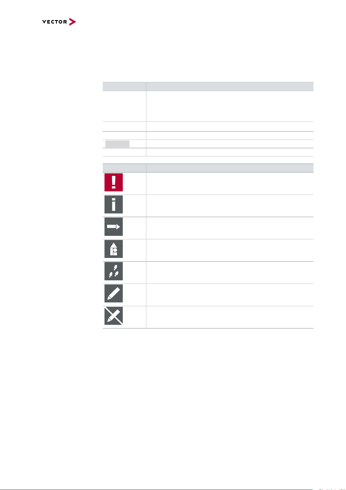
Conventions In the two following charts you will find the conventions used in the user manual
regarding utilized spellings and symbols.
Style Utilization
bold Blocks, surface elements, window- and dialog names of the soft-
ware. Accentuation of warnings and advices.
[OK]
File|Save
Microsoft
Source Code
Hyperlink Hyperlinks and references.
<CTRL>+<S> Notation for shortcuts.
Symbol Utilization
Legally protected proper names and side notes.
File name and source code.
This symbol calls your attention to warnings.
Push buttons in brackets
Notation for menus and menu entries
Here you can obtain supplemental information.
Here you can find additional information.
Here is an example that has been prepared for you.
Step-by-step instructions provide assistance at these points.
Instructions on editing files are found at these points.
This symbol warns you not to edit the specified file.
Manual VN5610/VN5610A Version 2.0 6
Page 7

1.2 Important Notes
1.2.1 Safety Instructions and Hazard Warnings
Caution!
In order to avoid personal injuries and damage to property, you have to read and
understand the following safety instructions and hazard warnings prior to installation
and use of this interface. Keep this documentation (manual) always near the interface.
1.2.1.1 Proper Use and Intended Purpose
Caution!
The interface is designed for analyzing, controlling and otherwise influencing control
systems and electronic control units. This includes, inter alia, bus systems like
CAN, LIN, K-Line, MOST, FlexRay, Ethernet, BroadR-Reach and/or ARINC 429.
1.2 Important Notes
The interface may only be operated in a closed state. In particular, printed circuits
must not be visible. The interface may only be operated (i) according to the instructions and descriptions of this manual; (ii) with the electric power supply designed for
the interface, e.g. USB-powered power supply; and (iii) with accessories manufactured or approved by Vector.
The interface is exclusively designed for use by skilled personnel as its operation
may result in serious personal injuries and damage to property. Therefore, only
those persons may operate the interface who (i) have understood the possible
effects of the actions which may be caused by the interface; (ii) are specifically
trained in the handling with the interface, bus systems and the system intended to
be influenced; and (iii) have sufficient experience in using the interface safely.
The knowledge necessary for the operation of the interface can be acquired in workshops and internal or external seminars offered by Vector. Additional and interface
specific information, such as „Known Issues“, are available in the „Vector KnowledgeBase“on Vector´s website at www.vector.com. Please consult the „Vector
KnowledgeBase“for updated information prior to the operation of the interface.
Manual VN5610/VN5610A Version 2.0 7
Page 8

1.2.1.2 Hazards
1.2.1.3 Disclaimer
1.2 Important Notes
Caution!
The interface may control and/or otherwise influence the behavior of control systems and electronic control units. Serious hazards for life, body and property may
arise, in particular, without limitation, by interventions in safety relevant systems
(e.g. by deactivating or otherwise manipulating the engine management, steering,
airbag and/or braking system) and/or if the interface is operated in public areas (e.g.
public traffic, airspace). Therefore, you must always ensure that the interface is
used in a safe manner. This includes, inter alia, the ability to put the system in
which the interface is used into a safe state at any time (e.g. by „emergency shutdown“), in particular, without limitation, in the event of errors or hazards.
Comply with all safety standards and public regulations which are relevant for the
operation of the system. Before you operate the system in public areas, it should be
tested on a site which is not accessible to the public and specifically prepared for
performing test drives in order to reduce hazards.
Caution!
Claims based on defects and liability claims against Vector are excluded to the
extent damages or errors are caused by improper use of the interface or use not
according to its intended purpose. The same applies to damages or errors arising
from insufficient training or lack of experience of personnel using the interface.
Manual VN5610/VN5610A Version 2.0 8
Page 9

1.2.2 Certification
1.2 Important Notes
Certified Quality
Management System
Vector Informatik GmbH has ISO 9001:2008 certification. The ISO standard is a globally recognized standard.
1.2.3 Warranty
Restriction
of warranty
We reserve the right to change the contents of the documentation and the software
without notice. Vector Informatik GmbH assumes no liability for correct contents or
damages which are resulted from the usage of the documentation. We are grateful for
references to mistakes or for suggestions for improvement to be able to offer you
even more efficient products in the future.
1.2.4 Registered Trademarks
Registered
trademarks
All trademarks mentioned in this documentation and if necessary third party
registered are absolutely subject to the conditions of each valid label right and the
rights of particular registered proprietor. All trademarks, trade names or company
names are or can be trademarks or registered trademarks of their particular proprietors. All rights which are not expressly allowed are reserved. If an explicit label of
trademarks, which are used in this documentation, fails, should not mean that a name
is free of third party rights.
> Windows, Windows 7, Windows 8.1, Windows 10
are trademarks of the Microsoft Corporation.
Manual VN5610/VN5610A Version 2.0 9
Page 10

2 Device Description
In this chapter you find the following information:
2.1 Scope of Delivery 11
2.2 Introduction 11
2.3 Accessories 12
2.4 Examples of Usage 13
2.4.1 Standalone Media Converter 13
2.4.2 Transparent Ethernet Monitoring 13
2.4.3 Remaining Bus Simulation 17
2.4.4 Diagnostics over IP 18
2.4.5 Avionics Full Duplex Switched Ethernet 19
2.5 VN5610 20
2.5.1 Connectors Ethernet Side 20
2.5.2 Connectors USB Side 21
2.5.3 LEDs 23
2.5.4 Technical Data 24
2.6 VN5610A 26
2.6.1 Connectors Ethernet Side 26
2.6.2 Connectors USB Side 27
2.6.3 LEDs 29
2.6.4 Technical Data 30
Manual VN5610/VN5610A Version 2.0 10
Page 11
2.1 Scope of Delivery
Contents The delivery includes:
> VN5610(A) Ethernet/CAN interface
> Vector Power Supply 12 V / 1.25 A (part number 05024)
> USB2.0 cable (part number 05011)
2.2 Introduction
2.1 Scope of Delivery
About the
VN5610(A)
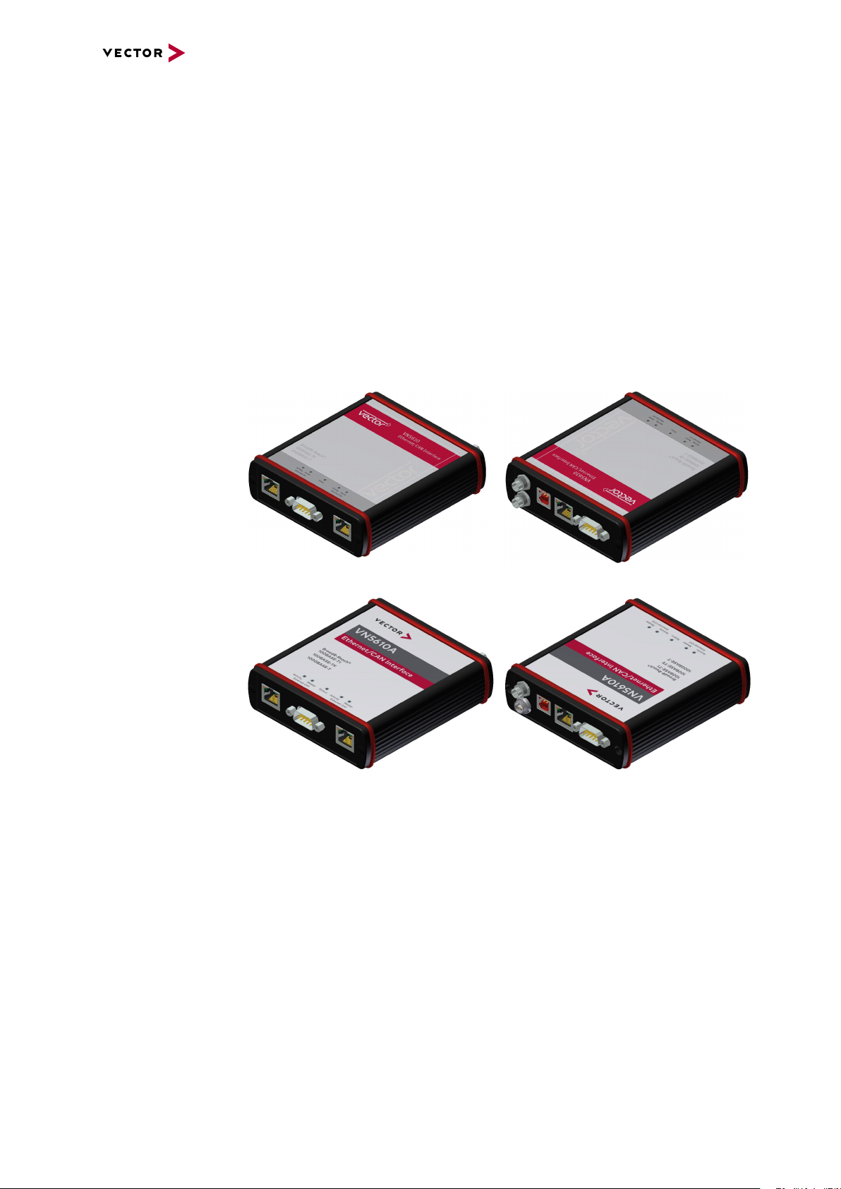
The VN5610(A) is a Vector network interface which supports the Ethernet physical
layer 10BASE-T, 100BASE-T1 (OPEN Alliance BroadR-Reach), 100BASE-TX and
1000BASE-T. 100BASE-T1 is a physical layer especially used in automotive electronics.
Figure 1: VN5610 Ethernet/CAN Interface
Figure 2: VN5610A Ethernet/CAN Interface
The VN5610(A) enables the transparent monitoring and logging of Ethernet data
streams and CAN events with minimal latency times and high resolution time stamps.
With this, the VN5610(A) enables a variety of applications such as simple bus analyses, complex remaining bus simulations as well as diagnostic and calibration (e.g.
with CANalyzer.Ethernet/CANoe.Ethernet).
Highlights Common features of VN5610 and VN5610A:
> Support of two independent Ethernet ports,
available as 2x RJ45 or 1x D-SUB9
> Support of standard Ethernet (10BASE-T/100BASE-TX/1000BASE-T)
> Support of two independent CAN/CAN FD channels,
available as 1x D-SUB9
> High resolution time stamps for Ethernet frames
Manual VN5610/VN5610A Version 2.0 11
Page 12

> High resolution time stamps for CAN/CAN FD frames
> Software and hardware time synchronization
of multiple Vector network interfaces
> Internal three-way-routing in/monitor/out
> Robustness, power supply and temperature ranges
suitable for automotive and industrial applications
Differences Differences between VN5610 and VN5610A:
VN5610
> Support of BroadR-Reach physical layer
VN5610A
> Support of 100BASE-T1 (OPEN Alliance BroadR-Reach)
> Support of one digital input/output (e.g. for DoIP Activation Line)
2.3 Accessories
2.3 Accessories
Reference
Information on available accessories can be found in the separate accessories
manual on the Vector Driver Disk in \Documentation\Accessories.
Manual VN5610/VN5610A Version 2.0 12
Page 13
2.4 Examples of Usage
CH1
VN5610(A)
CH2
Media Converter
PC/Standard Ethernet Logger
100BASE-TX
100BASE-T1
SensorSensor
ECU
SWITCH
ETH CH1
PC
USB
CANalyzer.Ethernet/CANoe.Ethernet
VN5610(A)
ETH CH2
Sensor
bypassing
Sensor
ECUECU
Sensor Sensor Sensor
SWITCH
Sensor
ECU
SWITCH
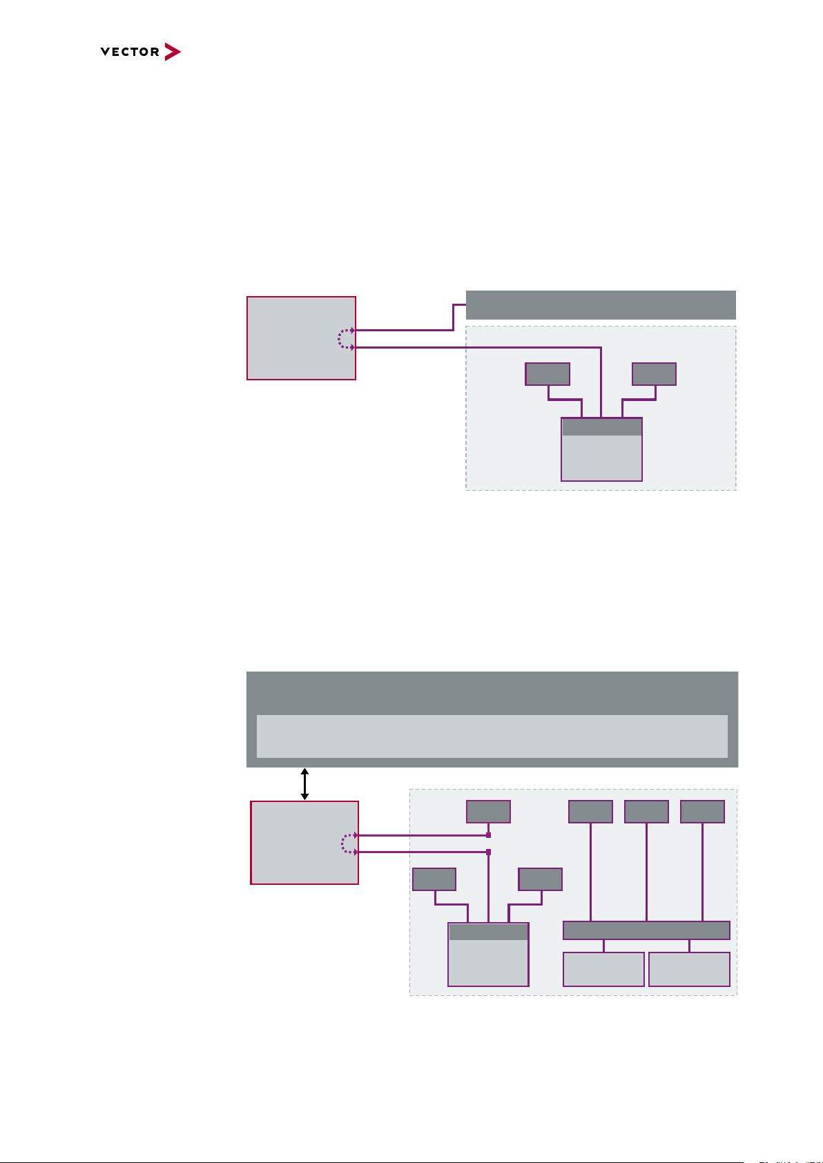
2.4.1 Standalone Media Converter
2.4 Examples of Usage
Physical layer
conversion
The Ethernet channels of the VN5610(A) can be configured independently. That way
the VN5610(A) can be used as a media converter between an ECU using the
100BASE-T1 physical layer and any standard Ethernet equipment (e.g. loggers)
using 100BASE-TX/1000BASE-T.
Setup
Figure 3: Media converter
2.4.2 Transparent Ethernet Monitoring
Monitoring The VN5610(A) can be used for Ethernet monitoring between an ECU and a con-
nected sensor without influencing the Ethernet bus (bypassing). In this particular
setup the VN5610(A) receives and forwards incoming data packages from one channel to the other.
Setup
Figure 4: Bypassing Ethernet data
This allows applications such as CANalyzer.Ethernet or CANoe.Ethernet to trace Ethernet data with accurate time stamps.
Manual VN5610/VN5610A Version 2.0 13
Page 14
2.4 Examples of Usage
VN5610(A)
ECU1
MAC
Ethernet Controller
PHY
BroadR-Reach
Transceiver
Rx
MAC
Ethernet Controller
PHY
BroadR-Reach
Transceiver
ECU2
Rx
PHY Bypassing
Δ
t
PC
CANalyzer.Ethernet/CANoe.Ethernet
Rx
Rx
Tx
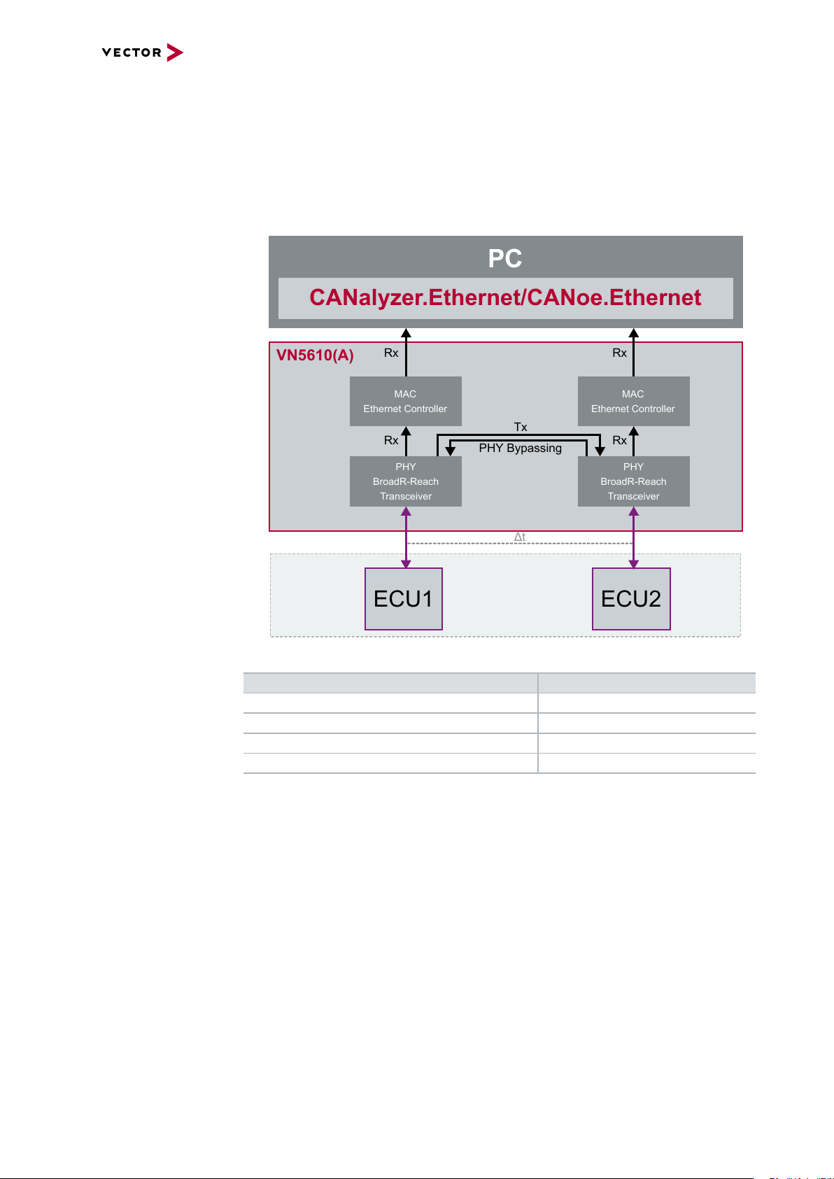
Bypassing modes For bypassing, two modes are available which can be used depending on the needed
application:
> PHY bypassing
Use this mode if you want to monitor Ethernet packets without influencing the constant processing time. Sending of additional Ethernet packets is not possible in
this mode.
Figure 5: PHY bypassing
Physical Layer Bypassing Latency ∆t
100BASE-T1100BASE-T1 2.3 µs
100BASE-T1100BASE-TX 1.8 µs
100BASE-TX100BASE-TX 1.4 µs
1000BASE-T1000BASE-T 0.5 µs
Manual VN5610/VN5610A Version 2.0 14
Page 15
2.4 Examples of Usage
VN5610(A)
MAC
Ethernet Controller
PHY
BroadR-Reach
Transceiver
Rx
MAC Bypassing
PC
CANalyzer.Ethernet/CANoe.Ethernet
Rx
Tx
ECU1
ECU2
Δ
t
Tx
MAC
Ethernet Controller
PHY
BroadR-Reach
Transceiver
RxRxTxTxTx
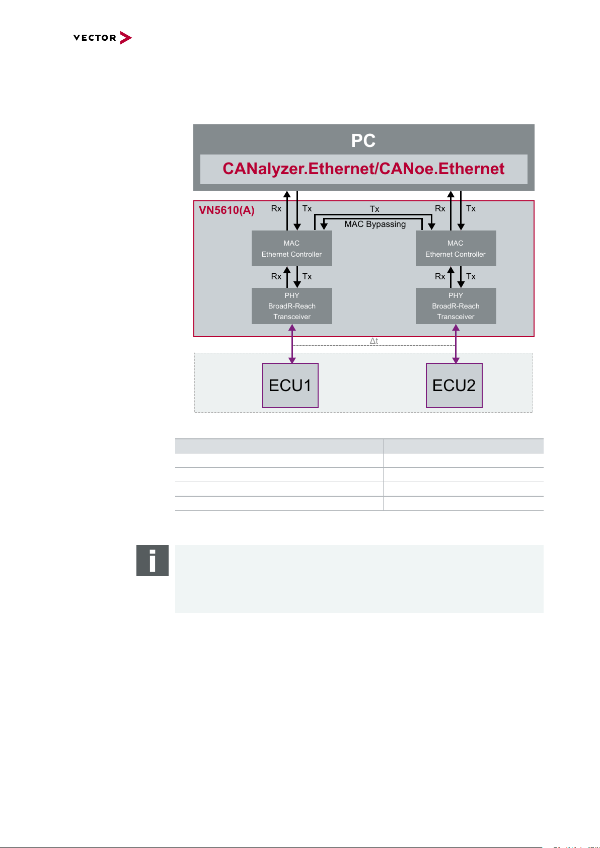
> MAC bypassing
Use this mode if you want to monitor Ethernet packets and also send additional
packets. In this mode, the processing time can be dynamic.
Figure 6: MAC bypassing
Physical Layer Bypassing Latency ∆t*
100BASE-T1100BASE-T1 approx. 4.6 µs
100BASE-T1100BASE-TX approx. 4.2 µs
100BASE-TX100BASE-TX approx. 3.8 µs
1000BASE-T1000BASE-T approx. 0.9 µs
* Processing time without additional frames through the application
(CANalyzer.Ethernet/CANoe.Ethernet)
Note
The MAC bypassing latency is independent of the frame length (Cut-through mode)
if there are no bypassing conflicts (e.g. additional frames sent by an application).
If additional frames are sent by an application, the bypass latency depends on the
frame length (Store-and-Forward Mode).
Manual VN5610/VN5610A Version 2.0 15
Page 16

2.4 Examples of Usage
ETH CH1
PC
CANalyzer.Ethernet/CANoe.Ethernet
ETH CH2
Sensor
Sensor
Sensor Sensor Sensor
Sensor
CAN
VN5610(A)
bypassing
Time Stamp Clock
USB
CAN
CH3
CAN
CH4
ECUECU
SWITCH
ECU
SWITCH
Time stamp clock for
Ethernet and CAN
The VN5610(A) uses a common time stamp clock for Ethernet and CAN events. So if
the measurement setup is extended by a CAN network, the generated CAN time
stamps are always in sync with the Ethernet time stamps which helps analyzing the
network.
Figure 7: Extended measuring setup
Note
Additional Vector network interfaces can be synchronized by software or hardware
(see section Time Synchronization on page 43).
Manual VN5610/VN5610A Version 2.0 16
Page 17

2.4 Examples of Usage
PC
CANalyzer.Ethernet/CANoe.Ethernet
CAN
ECU
CAN
CH3
CAN
CH4
ETH CH1
ETH CH2
VN5610(A)
Time Stamp Clock
ECUECU
Sensor
CANoe
ETH SIM #1
Sensor
SWITCH
CANoe
ETH SIM
#1
CANoe
ETH SIM
#2
CANoe
CAN SIM
#2
CANoe
CAN SIM
#1
ECU
CANoe
ETH SIM #2
CAN
Gateway
CANoe
CAN SIM #1
CANoe
CAN SIM #2
USB
2.4.3 Remaining Bus Simulation
Developing networks The VN5610(A) is able to send and receive data packages on two separate Ethernet
channels as well as events on two separate CAN channels. With this, the VN5610(A)
is a perfect choice for the remaining bus simulation during the development of complex networks.
Setup
Figure 8: Simulated nodes
Note
For the remaining bus simulation CANoe.Ethernet is required.
Manual VN5610/VN5610A Version 2.0 17
Page 18

2.4 Examples of Usage
PC
CANalyzer.Ethernet/CANoe.Ethernet
CAN
ECU
CAN
CH3
CAN
CH4
ETH CH1
VN5610A
Time Stamp Clock
CANoe
ETH SIM
#1
ECU
CANoe
ETH SIM #1
CAN
Gateway
USB
IO
100BASE-TX
DoIP Activation
2.4.4 Diagnostics over IP
DoIP activation line For diagnostics over IP, the VN5610A supports, beside the necessary 100BASE-TX
channel, an digital IO channel which has a DoIP activation line according to the ISO
specification. The activation level can be set by the VN5610A to switch the ECU to
diagnostic mode.
Setup
Figure 9: Simulated nodes
Note
For the diagnostics over IP with the VN5610A CANoe.Ethernet is required.
Manual VN5610/VN5610A Version 2.0 18
Page 19

2.4 Examples of Usage
Sensor Sensor
PC
USB
CANalyzer.AFDX/CANoe.AFDX
ETH CH1
ETH CH2
ECU
SWITCH
Sensor Sensor
ECU
SWITCH
VN5610(A)
2.4.5 Avionics Full Duplex Switched Ethernet
Redundant networks The VN5610(A) and its independent Ethernet channels are suitable for monitoring and
stressing safety-critical networks like in AFDX. Ethernet frames can be simultaneously sent over both channels as well as received with high resolution time
stamps. With this, the VN5610(A) is suitable for AFDX measurements and test
benches.
Setup
Figure 10: Redundant networ ks
Note
To access AFDX networks with the VN5610(A) either CANalyzer.AFDX or
CANoe.AFDX is required.
Manual VN5610/VN5610A Version 2.0 19
Page 20

2.5 VN5610
ACT SPEED ACT SPEED
5
4
3
2
1
6
7
8
9
N
P
Shield
CH1
CH2
Not connected
Not connected
Not connected
Not connected
P
N
Shield
2.5.1 Connectors Ethernet Side
Device connectors
Figure 11: Ethernet CH1, D-SUB9 (BroadR-Reach), Ethernet CH2
2.5 VN5610
> Ethernet CH1/CH2 (RJ45)
Standard Ethernet connector for
10BASE-T, 100BASE-TX and
LED ACT
- Illuminates if there is an Ethernet link.
- Blinks if there is Ethernet activity.
1000BASE-T.
LED SPEED
- Off: 10 Mbit
- Orange: 100 Mbit
- Green: 1000 Mbit
> Ethernet CH1/CH2 (D-SUB9)
D-SUB9 connector for BroadR-Reach. Use the BRcable 2Y to access both channels on separate D-SUB9 connectors (see accessories manual, part number
05103).
Pin Assignment
1 CH2 P
2 CH2 N
3 Shield
4 CH1 P
5 CH1 N
6 Not connected
7 Not connected
8 Not connected
9 Not connected
Reference
The Ethernet configuration can be done in Vector Hardware Config (see section
Device Configuration on page 35).
Manual VN5610/VN5610A Version 2.0 20
Page 21

2.5.2 Connectors USB Side
ACT SPEED
VCC
1
2
3
Power
1
2
3
Sync
GND
Sync
GND
Power/Sync
Power/Sync
SYNC
GND
Power
3
1
2
Device connectors
Figure 12: Connectors on the USBside
> 2x Power/Sync (Binder connector)
The VN5610 has two power/sync connectors (Binder type 711) which can be used
for time synchronization of different Vector devices (see section Time Synchronization on page 43) or for power. It does not matter which connector is used
to supply the device.
2.5 VN5610
Figure 13: Internal wiring of the power/sync connector
Pin Assignment
1 Power supply (6 V … 50 V DC, typ. 12 V)
2 Synchronization line
3 Ground
Note
The VN5610 requires at least 8 V to power up. Afterwards the power supply can be
reduced to 6 V for operation (typ. 12 V DC). The need of an external power supply
depends on the Ethernet configuration (see table).
Ethernet
Configuration
Disabled 100BASE-T1 100BASE-TX 1000BASE-T
Channel 1
Channel 2
Disabled O O O O
100BASE-T1 O O O X
100BASE-TX O O O X
1000BASE-T O X X X
O: bus-powered (also when both CAN channels in use), X: external power supplyrecommended.
Note: CAN itself r equires no external power supply.
Manual VN5610/VN5610A Version 2.0 21
Page 22

2.5 VN5610
5
4
3
2
1
6
789
Shield
Reserved
1051cap CAN High
1051cap GND
1051cap CAN Low
1051cap CAN Low
1051cap GND
1051cap CAN High
Shield
CH3
CH4
Not connected
> USB
Connect your PC and the VN5610 over USB to install and to use the device with
measurement applications (CANoe, CANalyzer). Use the USB2.0 compliant
cable found in the delivery (USB extension cables may generate faults between
the PC and the device). Connect the device directly to a USB port at your PC or
use a USB hub with its own power supply (self-powered). The device can also be
powered via this connector.
> Host (Ethernet)
Host connector. Reserved for future purposes.
> CAN CH3/4 (D-SUB9)
D-SUB connector with two CAN channels. Use the CANcable 2Y to access both
channels on separate D-SUB9 connectors (see accessories manual, part number
05075).
Pin Assignment
1 CH4 CAN Low
2 CH3 CAN Low
3 CH3 GND
4 Reserved.
Please do not use.
5 Shield
6 CH4 GND
7 CH3 CAN High
8 CH4 CAN High
9 Not connected
Manual VN5610/VN5610A Version 2.0 22
Page 23

2.5.3 LEDs
LEDs on top side
2.5 VN5610
Figure 14: LEDs on VN5610(A)
> Activity (Ethernet CH1/CH2)
Same as LED ACT at RJ45 connectors. LED illuminates if there is an Ethernet
link or blinks if there is Ethernet activity at CH1/CH2.
Color Description
Green Link to RJ45.
Yellow Link to D-SUB9.
> Master (Ethernet CH1/CH2)
Illuminates if CH1/CH2 is configured as Master.
Color Description
Green PHY is configured as master on RJ45.
Yellow PHY is configured as master on D-SUB9.
> Status
Multicolored LED indicating the status.
Color Description
Green Blinks 4x at power up and illuminates afterwards.
Blinks quicker during an update progress. Please wait for the automatic reboot of the device (approx. 30 s) after the update has been finished.
Red An error has occurred. Please disconnect the power supply as well as
the USB cable. Re-connect the power supply and the USB cable and
try again.
Manual VN5610/VN5610A Version 2.0 23
Page 24

2.5.4 Technical Data
Ethernet channels Max. 2, selectable from:
CAN/CAN FD channels Max. 2
PC interface USB 2.0
Power supply Without external power supply:
2.5 VN5610
2x RJ45
10BASE-T, 100BASE-TX, 1000BASE-T
(on-board BCM54810 PHY)
1x D-SUB9 for 100BASE-T1
(OPEN Alliance BroadR-Reach; dual channel)
(on-board BCM54810 PHY)
(on-board TJA1051 transceivers)
1x D-SUB9 (dual channel)
CAN2.0: 2 MBit/s
CAN FD: up to 8 MBit/s
bus-powered at 100 Mbit operation mode
With external power supply:
6…50 V DC, typ. 12 V DC,
power-up: 8 V DC
Power consumption Approx. 2.5 W
Time stamps Resolution: 8 ns
Accuracy (in device): 1 µs
Accuracy software sync: typ. 50 µs
Accuracy hardware sync: typ. 1 µs
Temperature range Operation: -40 °C ... +65 °C
Storage: -40 °C ... +85 °C
Relative humidity
of ambient air
Dimensions (LxWxH) Approx. 125 mm x 106 mm x 32 mm
Operating system requirements Windows 7 SP1 (32 bit / 64 bit)
15 %...95 %, non-condensing
Windows 8.1 (32 bit / 64 bit)
Windows 10 (64 bit)
Manual VN5610/VN5610A Version 2.0 24
Page 25

Electrical isolation
Power/
Sync
USB
Case
Ethernet
Channel 1
12345
6789
BroadR-Reach
Ethernet
Channel 2
3 1
2
Logic
12345
6789
CAN
Channel 1/2
GND
ISO1
GND ISO_SYNC
GND
GND
GND
ISO2
GND
GND
Ethernet
Host
3 1
2
GND ISO_SYNC
Electrical
Isolation
Supply/Data
Connected
Shield
Shield
Shield
Shield
Shield
Shield
Shield
CH1
CH2
of the connectors
2.5 VN5610
Manual VN5610/VN5610A Version 2.0 25
Page 26

2.6 VN5610A
ACT SPEED ACT SPEED
5
4
3
2
1
6
7
8
9
N
P
CH1
CH2
Not connected
Not connected
Not connected
Not connected
P
N
Not connected
2.6.1 Connectors Ethernet Side
Device connectors
Figure 15: Ethernet CH1, D-SUB9 (100BASE-T1) , Ethernet CH2
2.6 VN5610A
> Ethernet CH1/CH2 (RJ45)
Standard Ethernet connector for
10BASE-T, 100BASE-TX and
LED ACT
- Illuminates if there is an Ethernet link.
- Blinks if there is Ethernet activity.
1000BASE-T.
LED SPEED
- Off: 10 Mbit
- Orange: 100 Mbit
- Green: 1000 Mbit
> Ethernet CH1/CH2 (D-SUB9)
D-SUB9 connector for 100BASE-T1. Use the BRcable 2Y to access both channels on separate D-SUB9 connectors (see accessories manual, part number
05103).
Pin Assignment
1 CH2 P
2 CH2 N
3 Not connected
4 CH1 P
5 CH1 N
6 Not connected
7 Not connected
8 Not connected
9 Not connected
Reference
The Ethernet configuration can be done in Vector Hardware Config (see section
Device Configuration on page 35).
Manual VN5610/VN5610A Version 2.0 26
Page 27

2.6.2 Connectors USB Side
ACT SPEED
3 1
2
1
2
Digital Input/Ouput
Isolation
455R
Ri
50R
50R
Vcc
GND_ISO
Passive
Network
From Processor
To Processor
GND_ISO
10k
Device connectors
Figure 16: Connectors on the USBside
> Power/sync (Binder connector)
The VN5610A has one power/sync connector (Binder type 711) which can be used
for time synchronization of different Vector devices (see section Time Synchronization on page 43) or for power.
Pin Assignment
1 Power supply (6 V … 50 V DC, typ. 12 V)
2 Synchronization line
3 Ground
2.6 VN5610A
> IO (Lemo connector)
The VN5610A has a Lemo connector (CH5) for dedicated digital input/output
tasks. The pin assignment is as follows:
Pin Assignment
1 Digital input/output (see technical data)
2 Ground
Figure 17: Digital input /output
Manual VN5610/VN5610A Version 2.0 27
Page 28

2.6 VN5610A
5
4
3
2
1
6
789
Not connected
Reserved
1051cap CAN High
1051cap GND
1051cap CAN Low
1051cap CAN Low
1051cap GND
1051cap CAN High
CH3
CH4
Not connected
Note
The VN5610A requires at least 8 V to power up. Afterwards the power supply can
be reduced to 6 V for operation (typ. 12 V DC). The need of an external power supply depends on the Ethernet configuration (see table).
Ethernet
Configuration
Disabled 100BASE-T1 100BASE-TX 1000BASE-T
Channel 1
Channel 2
Disabled O O O O
100BASE-T1 O O O X
100BASE-TX O O O X
1000BASE-T O X X X
O: bus-powered (also when both CAN channels in use), X: external power supplyrecommended.
Note: CAN itself r equires no external power supply.
> USB
Connect your PC and the VN5610A over USB to install and to use the device with
measurement applications (CANoe, CANalyzer). Use the USB2.0 compliant
cable found in the delivery (USB extension cables may generate faults between
the PC and the device). Connect the device directly to a USB port at your PC or
use a USB hub with its own power supply (self-powered). The device can also be
powered via this connector.
> Host (Ethernet)
Host connector. Reserved for future purposes.
> CAN CH3/4 (D-SUB9)
D-SUB connector with two CAN channels. Use the CANcable 2Y to access both
channels on separate D-SUB9 connectors (see accessories manual, part number
05075).
Pin Assignment
1 CH4 CAN Low
2 CH3 CAN Low
3 CH3 GND
4 Reserved.
Please do not use.
5 Not connected
6 CH4 GND
7 CH3 CAN High
8 CH4 CAN High
9 Not connected
Manual VN5610/VN5610A Version 2.0 28
Page 29

2.6.3 LEDs
LEDs on top side
2.6 VN5610A
Figure 18: LEDs on VN5610(A)
> Activity (Ethernet CH1/CH2)
Same as LED ACT at RJ45 connectors. LED illuminates if there is an Ethernet
link or blinks if there is Ethernet activity at CH1/CH2.
Color Description
Green Link to RJ45.
Yellow Link to D-SUB9.
> Master (Ethernet CH1/CH2)
Illuminates if CH1/CH2 is configured as Master.
Color Description
Green PHY is configured as master on RJ45.
Yellow PHY is configured as master on D-SUB9.
> Status
Multicolored LED indicating the status.
Color Description
Green Blinks 4x at power up and illuminates afterwards.
Blinks quicker during an update progress. Please wait for the automatic reboot of the device (approx. 30 s) after the update has been finished.
Red An error has occurred. Please disconnect the power supply as well as
the USB cable. Re-connect the power supply and the USB cable and
try again.
Manual VN5610/VN5610A Version 2.0 29
Page 30

2.6.4 Technical Data
Ethernet channels Max. 2, selectable from:
CAN/CAN FD channels Max. 2
Digital input/output 1x Lemo
2.6 VN5610A
2x RJ45
10BASE-T, 100BASE-TX, 1000BASE-T
(on-board BCM54810 PHY)
1x D-SUB9 for 100BASE-T1
(OPEN Alliance BroadR-Reach; dual channel)
(on-board BCM89811 PHY)
(on-board TJA1051 transceivers)
1x D-SUB9 (dual channel)
CAN2.0: 2 MBit/s
CAN FD: up to 8 MBit/s
Push/pull mode (e.g. DoIP Activation Line)
or
Push mode only (e.g. Wake-up Triggers)
Output high (no load): 13V
Output high (load 346Ω): 5.3V
Output low: 0V
Input range: 0V…16V
Input: Schmitt trigger high 3.4V
Input: Schmitt trigger low 2.5V
Rout: 503Ω
PC interface USB 2.0
Power supply Without external power supply:
bus-powered at 100 Mbit operation mode
With external power supply:
6…50 V DC, typ. 12 V DC,
power-up: 8 V DC
Power consumption Approx. 2.5 W
Time stamps Resolution: 8 ns
Accuracy (in device): 1 µs
Accuracy software sync: typ. 50 µs
Accuracy hardware sync: typ. 1 µs
Temperature range Operation: -40 °C ... +65 °C
Storage: -40 °C ... +85 °C
Relative humidity
of ambient air
Dimensions (LxWxH) Approx. 125 mm x 106 mm x 32 mm
Operating system requirements Windows 7 SP1 (32 bit / 64 bit)
15 %...95 %, non-condensing
Windows 8.1 (32 bit / 64 bit)
Windows 10 (64 bit)
Manual VN5610/VN5610A Version 2.0 30
Page 31

Electrical isolation
Power/
Sync
USB
Case
Ethernet
Channel 1
12345
6789
BroadR-Reach
Ethernet
Channel 2
Logic
12345
6789
CAN
Channel 1/2
GND
ISO1
GND ISO
GND
GND
ISO2
GND
Ethernet
Host
3 1
2
GND ISO_SYNC
Electrical
Isolation
Supply/Data
Connected
Shield
Shield
Shield
Shield
Shield
Shield
Shield
CH1
CH2
1
2
of the connectors
2.6 VN5610A
Manual VN5610/VN5610A Version 2.0 31
Page 32

2.6 VN5610A
3 Getting Started
In this chapter you find the following information:
3.1 Driver Installation 33
3.2 Device Configuration 35
3.3 Loop Tests 37
3.4 Ethernet 37
Manual VN5610/VN5610A Version 2.0 32
Page 33

3.1 Driver Installation
3.1 Driver Installation
General
information
The Vector Driver Disk offers a driver setup which allows the installation or the
removal of Vector devices.
Note
Please note that you will need Administrator Rights for the following steps.
Step by Step Procedure
1. Execute the driver setup from the autostart menu or directly from
\Drivers\Setup.exe before the device is connected to the PC with the
included USB cable.
If you have already connected the device to the PC, the Windows found new
Hardware wizard appears. Close this wizard and then execute the driver setup.
2. Click [Next] in the driver setup dialog. The initialization process starts.
Manual VN5610/VN5610A Version 2.0 33
Page 34

3.1 Driver Installation
3. In the driver selection dialog, select your devices to be installed (or to be uninstalled).
4. Click [Install] to execute the driver installation, or [Uninstall] to remove exist-
ing drivers.
5. A confirmation dialog appears. Click [Close] to exit. After successful installation, the device is ready for operation and can be connected to the PC with
the included USB cable.
Manual VN5610/VN5610A Version 2.0 34
Page 35

3.2 Device Configuration
3.2 Device Configuration
Configuration Before the installed device can be used in an application, it must be properly con-
figured for the needed use case. This configuration is done with the Vector Hardware
Config tool which comes with the driver installation. The tool can be found in Win-
dows | Start | Settings | Control Panel | Vector Hardware and manages all
installed Vector devices.
Reference
Further details on Vector Hardware Config can be found in the installation instruc-
tions (see section Vector Hardware Configuration on page 38).
Device configuration If you want to change the Ethernet configuration, select a connected
VN5610/VN5610A from the list and double click on Device Configuration.
Figure 19: Vector Hardware Config
Figure 20: Device Configuration dialog
Manual VN5610/VN5610A Version 2.0 35
Page 36

3.2 Device Configuration
Note
In order to get a working Ethernet link between the VN5610/VN5610A and another
Ethernet device, the auto negotiation has to be activated in both devices.
Alternatively, both devices can be manually configured with the same parameters
(only full duplex mode).
Please note that the Ethernet link will run in half duplex mode if one device uses
auto negotiation while the other one is manually configured. The VN5610/VN5610A
supports only full duplex mode.
Note
You can also change the Ethernet settings in the Network Hardware Configuration of CANoe.Ethernet /CANalyzer.Ethernet:
Figure 21: Network Hardware Configuration
Figure 22: Network Hardware Configuration
Manual VN5610/VN5610A Version 2.0 36
Page 37

3.3 Loop Tests
6
7
8
9
P CH1/CH2
N CH1/CH2
5
4
3
2
1
3.3 Loop Tests
Operation test The test described here can be performed to check the functional integrity of the driver
and the device. This test is identical for Windows 7 / Windows 8.1 / Windows 10 and
independent of the used application.
3.4 Ethernet
Device test The operating test for Ethernet can be executed with the following devices:
> VN5610
> VN5610A
Step by Step Procedure
1. Connect both Ethernet channels of the device with an Ethernet cable.
2. Connect both BroadR-Reach channels at the D-SUB9 connector as follows
(e.g. with the BRcable 2Y, part number 05103):
3. Start \Drivers\Common\ETHloop.exe from the Vector Driver Disk.
4. Select the connected channels from the list.
5. Press [Twinkle] and check if the LED Status blinks.
6. Start the test by pressing the button [Start Test]. The test is successful if no
error messages occur.
Manual VN5610/VN5610A Version 2.0 37
Page 38

4 Vector Hardware Configuration
In this chapter you find the following information:
4.1 General Information 39
4.2 Tool Description 40
4.2.1 Introduction 40
4.2.2 Tree View 41
Manual VN5610/VN5610A Version 2.0 38
Page 39

4.1 General Information
4.1 General Information
Executing Vector
Hardware Config
Control Panel
Windows 7
Control Panel
Windows 8.1
After the successful driver installation you will find the configuration application
Vector Hardware in the Control Panel (see below). The tool gives you information
about the connected and installed Vector devices. There are also several settings that
can be changed.
Figure 23: Icon in Control Panel
> Category view
Windows Start | Control Panel | Hardware and Sound,
click Vector Hardware in the list.
> Symbols view
Windows Start | Control Panel,
click Vector Hardware in the list.
> Category view
<Windows key>+<X> | Control Panel | Hardware and Sound,
click Vector Hardware in the list.
> Symbols view
<Windows key>+<X> | Control Panel,
click Vector Hardware in the list.
Control Panel
Windows 10
> Category view
<Windows key>+<X> | Control Panel | Hardware and Sound,
click Vector Hardware in the list.
> Symbols view
<Windows key>+<X> | Control Panel,
click Vector Hardware in the list.
Manual VN5610/VN5610A Version 2.0 39
Page 40

4.2 Tool Description
physical CH1
CAN
physical CH2
LIN
Vector Device 1
Vector Device 2
physical CH1
FlexRay
physical CH2
CAN
not assigned
l
ogical channel
CAN 1
Application
l
ogical channel
LIN 1
l
ogical channel
CAN 1
l
ogical channel
FlexRay 1
l
ogical channel
CAN 2
4.2.1 Introduction
Vector
Hardware Config
Figure 24: General view of Vector Hardware Config
4.2 Tool Description
Logical and physical
channels
Vector Hardware Config enables the channel configuration between installed Vector
devices and applications. Applications use so-called logical channels which are hardware independent and have to be assigned to real hardware channels.
Figure 25: Concept of channel assignments
Manual VN5610/VN5610A Version 2.0 40
Figure 26: Channel assignment in Vector Hardware Config
Page 41

4.2.2 Tree View
4.2 Tool Description
Accessing
Vector devices
The tool is split into two windows. The left window has a tree view and lets you
access the installed Vector devices, the right window displays the details of the selection. The following nodes are available in the tree view:
Hardware The Hardware section lists the installed Vector devices. Each device item has phys-
ical channels which can be assigned to any number of logical channels (e.g. CANalyzer CAN 1). A logical channel can be assigned to only one physical channel.
Figure 27: Hardware
Application In Application, all available applications are displayed in a tree view. According to
each application, the assignments of logical and physical channels are displayed in
the right part of the window. If no assignment exists, the information Not assigned
appears. The assignment can be edited via a right-click.
Figure 28: Application
Manual VN5610/VN5610A Version 2.0 41
Page 42

4.2 Tool Description
General information General information contains overall information on Vector devices and appli-
cations, e.g. software time synchronization, transmit queue size, configuration flags,
the number of virtual CAN devices or the driver status.
Figure 29: General information
License The License section contains information on all current available licenses (Vector bus
devices, Vector License USB dongle devices).
Figure 30: License
Reference
You will find a detailed description of Vector Hardware Config in the online help
(Help | Contents).
Manual VN5610/VN5610A Version 2.0 42
Page 43

5 Time Synchronization
In this chapter you find the following information:
5.1 General Information 44
5.2 Software Sync 46
5.3 Hardware Sync 47
Manual VN5610/VN5610A Version 2.0 43
Page 44

5.1 General Information
CAN
Vector
CAN Interface
CH1
CH2
Time Stamp Clock
PC
CANalyzer/CANoe
USB
5.1 General Information
Time stamps
and events
Generating
time stamps
Time stamps are useful when analyzing incoming or outgoing data or event
sequences on a specific bus.
Figure 31: Time stamps of two CAN channels in CANalyzer
Each event which is sent or received by a Vector network interface has an accurate
time stamp. Time stamps are generated for each channel in the Vector network interface. The base for these time stamps is a common hardware clock in the device.
Figure 32: Common time stamp clock for each channel
If the measurement setup requires more than one Vector network interface, a synchronization of all connected interfaces and their hardware clocks is needed.
Due to manufacturing and temperature tolerances, the hardware clocks may vary in
speed, so time stamps of various Vector devices drift over time.
Manual VN5610/VN5610A Version 2.0 44
Page 45

5.1 General Information
CAN
FlexRay
Vector
CAN Interface
CH1
CH2
Time Stamp Clock
PC
Vector
FR Interface
CHA
CHB
Time Stamp Clock
sec
0.000000
0.100376
0.200382
0.300372
0.400406
0.500593
0.600242
sec
0.000000
0.1003
83
0.200
982
0.30
1456
0.40
2612
0.50
3885
0.60
4092
CANalyzer/CANoe
USB
USB
Figure 33: Example of unsynchronized network interfaces. Independent time stamps drift apart
To compensate for these time stamp deviations between the Vector network interfaces, the time stamps can be either synchronized by software or by hardware (see
next section).
Note
The accuracy of the software and hardware sync depends on the interface. Further
information on specific values can be found in the technical data of the respective
devices.
Manual VN5610/VN5610A Version 2.0 45
Page 46

5.2 Software Sync
CAN
FlexRay
Vector
CAN Interface
CH1
CH2
Time Stamp Clock
Vector
FR Interface
CHA
CHB
Time Stamp Clock
synchronization
by software (PC clock)
sec
0.000000
1.100
356
1.200
362
2.300
362
2.400
356
3.500
353
3.600
362
PC
sec
0.000000
1.100
413
1.200
421
2.300
429
2.400
419
3.500
415
3.600
420
PC clock
CANalyzer/CANoe
USB
USB
5.2 Software Sync
Synchronization
by software
The software time synchronization is driver-based and available for all applications
without any restrictions. The time stamp deviations from different Vector network interfaces are calculated and synchronized to the common PC clock. For this purpose no
further hardware setup is required.
Figure 34: Time stamps of devices are synchronized to the PC clock
The setting of the software time synchronization can be changed in the Vector Hard-
ware Config tool in General information | Settings | Software time synchronization.
Figure 35: Switching on the software synchronization
> YES
The software time synchronization is active.
> NO
The software time synchronization is not active. Use this setting only if the Vector
network interfaces are being synchronized over the sync line or if only a single
device is used.
Manual VN5610/VN5610A Version 2.0 46
Page 47

5.3 Hardware Sync
VN1630A
VN5610A
VN1640A
Multi
SYNCbox
external
VN1640A
USB PC
PC
VN7570
SYNCcable XL
SYNCcable XL
SYNCcable XL
SYNCcable XL
USB PC
Vector Devices
USB PC
USB PC
USB PC
VN5610A
VN8912A
Power
VN5610A
VN1640A
Multi
SYNCbox
external
VN1640A
USB VN8912A
USB PC
SYNCcable XL
SYNCcable XL
SYNCcable XL
SYNCcable XL
5.3 Hardware Sync
Synchronization
by hardware
A more accurate time synchronization of multiple devices is provided by the hardware
synchronization which has to be supported by the application (e.g. CANalyzer, CANoe). Two Vector network interfaces can therefore be connected with the SYNCcableXL (see accessories manual, part number 05018).
In order to synchronize up to five devices at the same time, a distribution box is available (see accessories manual, part number 05085).
Figure 36: Example of a time synchronization with multipledevices
Manual VN5610/VN5610A Version 2.0 47
Figure 37: Example of a time synchronization with VN8912 and additional devices
At each falling edge on the sync line which is initiated by the application, the Vector
network interface generates a time stamp that is provided to the application. This
allows the application to calculate the deviations between the network interfaces and
Page 48

5.3 Hardware Sync
CANalyzer/CANoe
CAN
FlexRay
Vector
CAN Interface
CH2
Time Stamp Clock
USB
Vector
FR Interface
CHB
Master Time Stamp Clock
synchronization
by hardware (SYNCcable)
sec
0.000000
1.10037
5
1.20038
1
2.30037
1
2.40040
5
3.50059
2
3.60024
1
CH1
CHA
sec
0.000000
1.100376
1.200382
2.300372
2.400406
3.500593
3.600242
PC
USB
to synchronize the time stamps to a common time base (master clock) which is
defined by the application.
Figure 38: Time stamps are synchronized to the master clock
Note
The hardware synchronization must be supported by the application. For further
information please refer to the relevant application manual. Please note that the software synchronization must be disabled (see Vector Hardware Config | General
information | Settings | Software time synchronization) if the hardware synchronization is used.
Manual VN5610/VN5610A Version 2.0 48
Page 49

Get More Information
Visit our website for:
> News
> Products
> Demo software
> Support
> Training classes
> Addresses
www.vector.com
 Loading...