

Page 1
VN5000 Ethernet Interface Family
Manual
Version 2.5|English
vector.com
Page 2

Imprint
Vector InformatikGmbH
Ingersheimer Straße 24
D-70499 Stuttgart
The information and data given in this user manual can be changed without prior notice. No part of this manual may be reproduced in any
form or by any means without the written permission of the publisher, regardless of which method or which instruments, electronic or
mechanical, are used. Alltechnicalinformation, drafts, etc. are liable to law of copyright pr otection.
© Copyright 2021, Vector Informatik GmbH. All rights reserved.
Page 3

Contents
Contents
1 Introduction 8
1.1 About this User Manual 9
1.1.1 Warranty 10
1.1.2 Registered Trademarks 10
1.2 Important Notes 11
1.2.1 Safety Instructions and Hazard Warnings 11
1.2.1.1 Proper Use and Intended Purpose 11
1.2.1.2 Hazards 12
1.2.2 Disclaimer 12
1.2.3 Licenses 12
1.2.3.1 Google Protocol Buffer 12
1.2.3.2 Petteri Aimonen Nano Protocol Buffer 12
2 General Information 13
2.1 Manual Validity 14
2.2 Examples of Usage 15
2.2.1 Transparent Ethernet Monitoring 15
2.2.2 Remaining Bus Simulation 17
2.2.3 Standalone Media Converter 18
2.2.4 Diagnostics over IP 19
2.2.5 Port Mirroring 20
3 VN5610A 21
3.1 Scope of Delivery 22
3.2 Introduction 22
3.3 Connectors Ethernet Side 24
3.3.1 Connectors USB Side 25
3.3.2 LEDs 27
3.3.3 Technical Data 28
3.3.3.1 Overview 28
3.3.3.2 Electrical Isolation 29
3.3.3.3 Network Features 31
3.4 Accessories 32
4 VN5620 33
4.1 Scope of Delivery 34
4.2 Introduction 34
4.3 Connectors 36
4.3.1 Front Side 36
VN5000 Manual Version 2.5 3
Page 4

Contents
4.3.2 Back Side 38
4.4 LEDs 40
4.5 Technical Data 41
4.5.1 Overview 41
4.5.2 Temperature Shutdown 41
4.5.3 Electrical Isolation 43
4.5.4 Network Features 45
4.6 Accessories 46
5 VN5430 47
5.1 Scope of Delivery 48
5.2 Introduction 48
5.3 Connectors 49
5.3.1 Front Side 49
5.3.2 Back Side 50
5.4 LEDs 51
5.5 Technical Data 52
5.5.1 Overview 52
5.5.2 Temperature Shutdown 52
5.5.3 Electrical Isolation 53
5.5.4 Network Features 55
5.6 Accessories 56
6 VN5640 57
6.1 Scope of Delivery 58
6.2 Introduction 58
6.3 Main Connectors 60
6.4 LEDs 64
6.5 Interface Option 100BASE-T1 66
6.5.1 Connectors 66
6.5.2 Technical Data 67
6.5.2.1 Overview 67
6.5.2.2 Electrical Isolation 68
6.5.3 Network Features 70
6.6 Interface Option 1000BASE-T1 71
6.6.1 Connectors 71
6.6.2 Technical Data 73
6.6.2.1 Overview 73
6.6.2.2 Electrical Isolation 74
VN5000 Manual Version 2.5 4
Page 5

Contents
6.6.2.3 Network Features 76
6.7 Accessories 77
7 VN5240 78
7.1 Scope of Delivery 79
7.2 Introduction 79
7.3 Connectors 81
7.3.1 Front Side 81
7.3.2 Back Side 82
7.4 LEDs 83
7.5 Technical Data 84
7.5.1 Overview 84
7.5.2 Temperature Shutdown 84
7.5.3 Electrical Isolation 86
7.5.4 Network Features 88
7.5.4.1 Physical Bypass Relay 89
7.6 Accessories 90
7.6.1 VSH Cable Guard 216 91
8 VN5650 94
8.1 Scope of Delivery 95
8.2 Introduction 95
8.3 Connectors 97
8.3.1 Front Side 97
8.3.2 Back Side 98
8.4 LEDs 102
8.5 Technical Data 103
8.5.1 Overview 103
8.5.2 Temperature Shutdown 104
8.5.3 Electrical Isolation 105
8.5.4 Network Features 107
8.5.4.1 Physical Bypass Relay 108
8.6 Accessories 109
8.6.1 VSH Cable Guard 216 110
9 Getting Started 113
9.1 Driver Installation 114
9.2 Ethernet Device Configuration 116
VN5000 Manual Version 2.5 5
Page 6

Contents
9.2.1 General Information 116
9.2.2 Network-based Ethernet Configuration 117
9.2.3 Example: Simple TAP Configuration 119
10 Vector Hardware Configuration 123
10.1 General Information 124
10.2 Tool Description 125
10.2.1 Introduction 125
10.2.2 Tree View 126
11 Vector Ethernet Device Configuration 129
11.1 Basic Concept 130
11.2 Example 131
11.3 Definitions 132
12 Time Synchronization 135
12.1 General Information 136
12.2 Software Sync 138
12.2.1 General Information 138
12.2.2 Configuration 139
12.3 Hardware Sync 140
12.3.1 General Information 140
12.3.2 Configuration 142
12.4 Precision Time Protocol Sync 143
12.4.1 General Information 143
12.4.2 Supported Features 143
12.4.3 Network Topology 144
12.4.4 Configuration 145
12.5 Protocol Combinations 146
12.6 Use Cases and Configuration Examples 147
12.6.1 GNSS Synchronization 147
12.6.2 4.2 IEEE1588 Synchronization 148
12.6.3 Hardware Synchronization 149
12.7 Compatibility 150
12.7.1 Vector Software 150
12.7.2 Device Drivers 150
12.8 Troubleshooting 151
VN5000 Manual Version 2.5 6
Page 7

Contents
13 Ethernet Host Connections 152
13.1 General Hints 153
13.2 Getting Started 154
13.2.1 Connecting the Device 154
13.2.2 Changing the IP Address 156
13.3 Windows Network Throttling 158
13.3.1 Issue 158
13.3.2 Solution 158
13.4 Jumbo Frames 159
13.4.1 Issue 159
13.4.2 Solution 159
13.5 Interrupt Moderation Rate 160
13.5.1 Issue 160
13.5.2 Solution 160
13.6 Known Issues with 3rd Party Hardware 161
13.6.1 Intel I218 / I219 Network Cards 161
VN5000 Manual Version 2.5 7
Page 8

1 Introduction
1 Introduction
In this chapter you find the following information:
1.1 About this User Manual 9
1.1.1 Warranty 10
1.1.2 Registered Trademarks 10
1.2 Important Notes 11
1.2.1 Safety Instructions and Hazard Warnings 11
1.2.2 Disclaimer 12
1.2.3 Licenses 12
VN5000 Manual Version 2.5 8
Page 9
1 Introduction
1.1 About this User Manual
Conventions In the two following charts you will find the conventions used in the user manual
regarding utilized spellings and symbols.
Style Utilization
bold Blocks, surface elements, window- and dialog names of the soft-
ware. Accentuation of warnings and advices.
[OK]
File|Save
Source Code
Hyperlink Hyperlinks and references.
<CTRL>+<S> Notation for shortcuts.
Symbol Utilization
File name and source code.
This symbol calls your attention to warnings.
Push buttons in brackets
Notation for menus and menu entries
Here you can obtain supplemental information.
Here you can find additional information.
Here is an example that has been prepared for you.
Step-by-step instructions provide assistance at these points.
Instructions on editing files are found at these points.
This symbol warns you not to edit the specified file.
VN5000 Manual Version 2.5 9
Page 10

1.1.1 Warranty
1 Introduction
Restriction
of warranty
We reserve the right to change the contents of the documentation and the software
without notice. Vector Informatik GmbH assumes no liability for correct contents or
damages which are resulted from the usage of the documentation. We are grateful for
references to mistakes or for suggestions for improvement to be able to offer you
even more efficient products in the future.
1.1.2 Registered Trademarks
Registered
trademarks
All trademarks mentioned in this documentation and if necessary third party
registered are absolutely subject to the conditions of each valid label right and the
rights of particular registered proprietor. All trademarks, trade names or company
names are or can be trademarks or registered trademarks of their particular proprietors. All rights which are not expressly allowed are reserved. If an explicit label of
trademarks, which are used in this documentation, fails, should not mean that a name
is free of third party rights.
► Windows, Windows 7, Windows 8.1, Windows 10
are trademarks of the Microsoft Corporation.
VN5000 Manual Version 2.5 10
Page 11

1.2 Important Notes
1.2.1 Safety Instructions and Hazard Warnings
Caution!
In order to avoid personal injuries and damage to property, you have to read and
understand the following safety instructions and hazard warnings prior to installation and use of this interface. Keep this documentation (manual) always near the
interface.
1.2.1.1 Proper Use and Intended Purpose
Caution!
The interface is designed for analyzing, controlling and otherwise influencing control systems and electronic control units. This includes, inter alia, bus systems like
CAN, LIN, K-Line, MOST, FlexRay, Ethernet, BroadR-Reach and/or ARINC 429.
1 Introduction
The interface may only be operated in a closed state. In particular, printed circuits
must not be visible. The interface may only be operated (i) according to the instructions and descriptions of this manual; (ii) with the electric power supply designed
for the interface, e.g. USB-powered power supply; and (iii) with accessories manufactured or approved by Vector.
The interface is exclusively designed for use by skilled personnel as its operation
may result in serious personal injuries and damage to property. Therefore, only
those persons may operate the interface who (i) have understood the possible
effects of the actions which may be caused by the interface; (ii) are specifically
trained in the handling with the interface, bus systems and the system intended to
be influenced; and (iii) have sufficient experience in using the interface safely.
The knowledge necessary for the operation of the interface can be acquired in
work-shops and internal or external seminars offered by Vector. Additional and
interface specific information, such as „Known Issues“, are available in the „Vector
KnowledgeBase“on Vector´s website at www.vector.com. Please consult the
„Vector KnowledgeBase“for updated information prior to the operation of the interface.
VN5000 Manual Version 2.5 11
Page 12

1.2.1.2 Hazards
1 Introduction
Caution!
The interface may control and/or otherwise influence the behavior of control systems and electronic control units. Serious hazards for life, body and property may
arise, in particular, without limitation, by interventions in safety relevant systems
(e.g. by deactivating or otherwise manipulating the engine management, steering,
airbag and/or braking system) and/or if the interface is operated in public areas
(e.g. public traffic, airspace). Therefore, you must always ensure that the interface
is used in a safe manner. This includes, inter alia, the ability to put the system in
which the interface is used into a safe state at any time (e.g. by „emergency shutdown“), in particular, without limitation, in the event of errors or hazards.
Comply with all safety standards and public regulations which are relevant for the
operation of the system. Before you operate the system in public areas, it should
be tested on a site which is not accessible to the public and specifically prepared
for performing test drives in order to reduce hazards.
1.2.2 Disclaimer
Caution!
Claims based on defects and liability claims against Vector are excluded to the
extent damages or errors are caused by improper use of the interface or use not
according to its intended purpose. The same applies to damages or errors arising
from insufficient training or lack of experience of personnel using the interface.
1.2.3 Licenses
1.2.3.1 Google Protocol Buffer
Reference
This device uses the Google Protocol Buffer. The license information can be found
in the separate text file on the Vector Driver Disk in \Docu-
mentation\Licenses.
1.2.3.2 Petteri Aimonen Nano Protocol Buffer
Reference
This device uses the Petteri Aimonen Nano Protocol Buffer. The license information can be found in the separate text file on the Vector Driver Disk in \Docu-
mentation\Licenses.
VN5000 Manual Version 2.5 12
Page 13

2 General Information
2 General Information
In this chapter you find the following information:
2.1 Manual Validity 14
2.2 Examples of Usage 15
2.2.1 Transparent Ethernet Monitoring 15
2.2.2 Remaining Bus Simulation 17
2.2.3 Standalone Media Converter 18
2.2.4 Diagnostics over IP 19
2.2.5 Port Mirroring 20
VN5000 Manual Version 2.5 13
Page 14

2.1 Manual Validity
Note
This manual is valid for the VN5000 interface family with effect from device driver
version 11.2.
Note
Driver version 11.2 introduces the network-based Ethernet configuration but still
supports the previous channel-based configuration (legacy mode).
This manual focuses on the new network-based Ethernet configuration. Therefor,
the mode of the VN5610 (A) or VN5640 interface has to be changed with the
Vector Hardware Config tool (see section Ethernet Device Configuration on page
116).
Note
The network-based Ethernet configuration requires at least CANoe V12.0 SP4 or
CANape V18!
2 General Information
Reference
For previous driver versions and the channel-based configuration, please refer to
the separate VN5610A or the VN5640 manual on the Vector Driver Disk:
\Documentation\VN5000 Interface Family\....
VN5000 Manual Version 2.5 14
Page 15
2 General Information
ETH Port 1
PC
USB/ETH
CANalyzer.Ethernet/CANoe.Ethernet
VN5000
ETH Port 2
Sensor
bypassing
Sensor
ECUECU
Sensor Sensor Sensor
SWITCH
Sensor
ECU
SWITCH
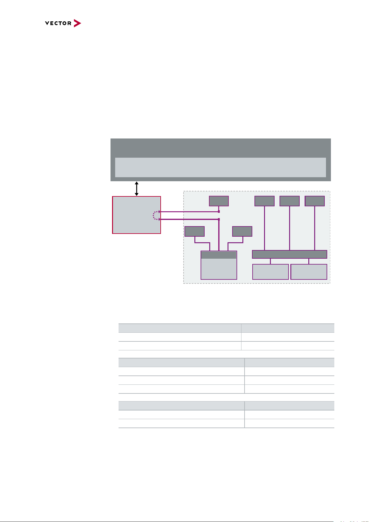
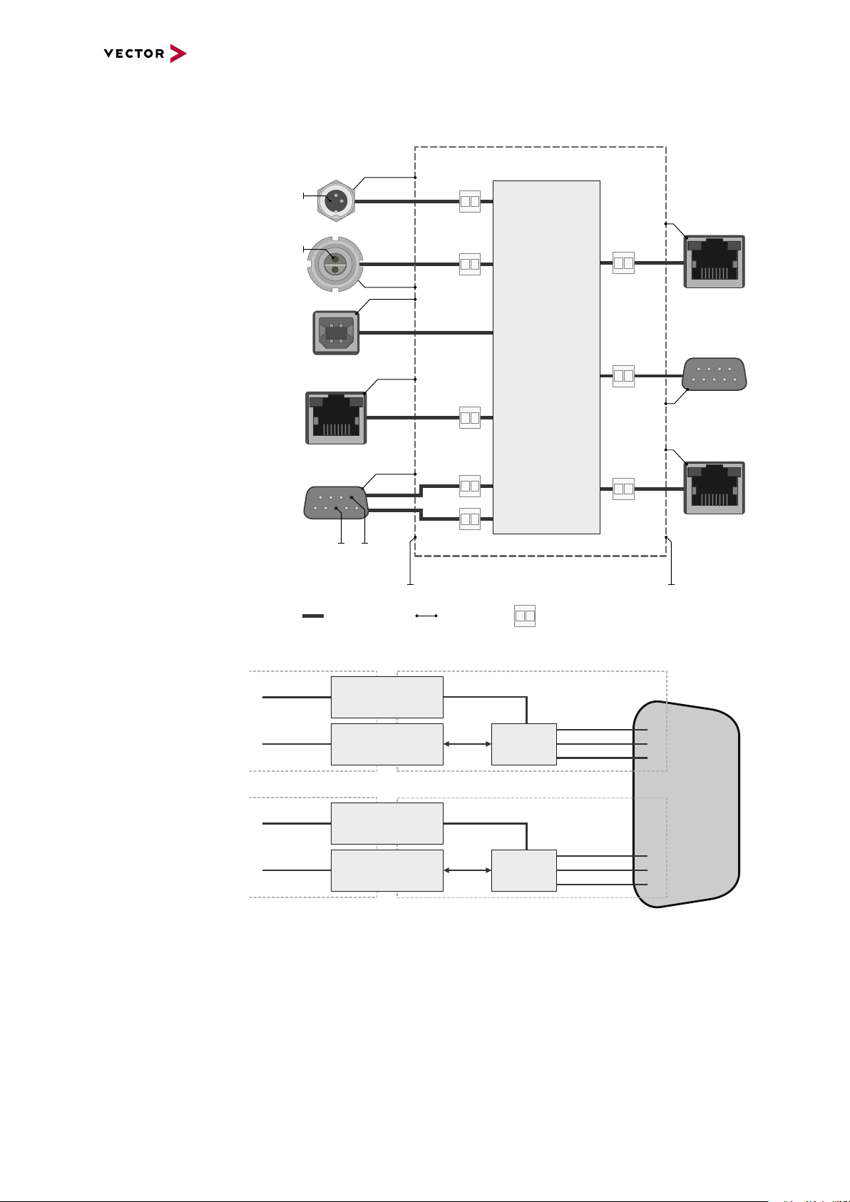
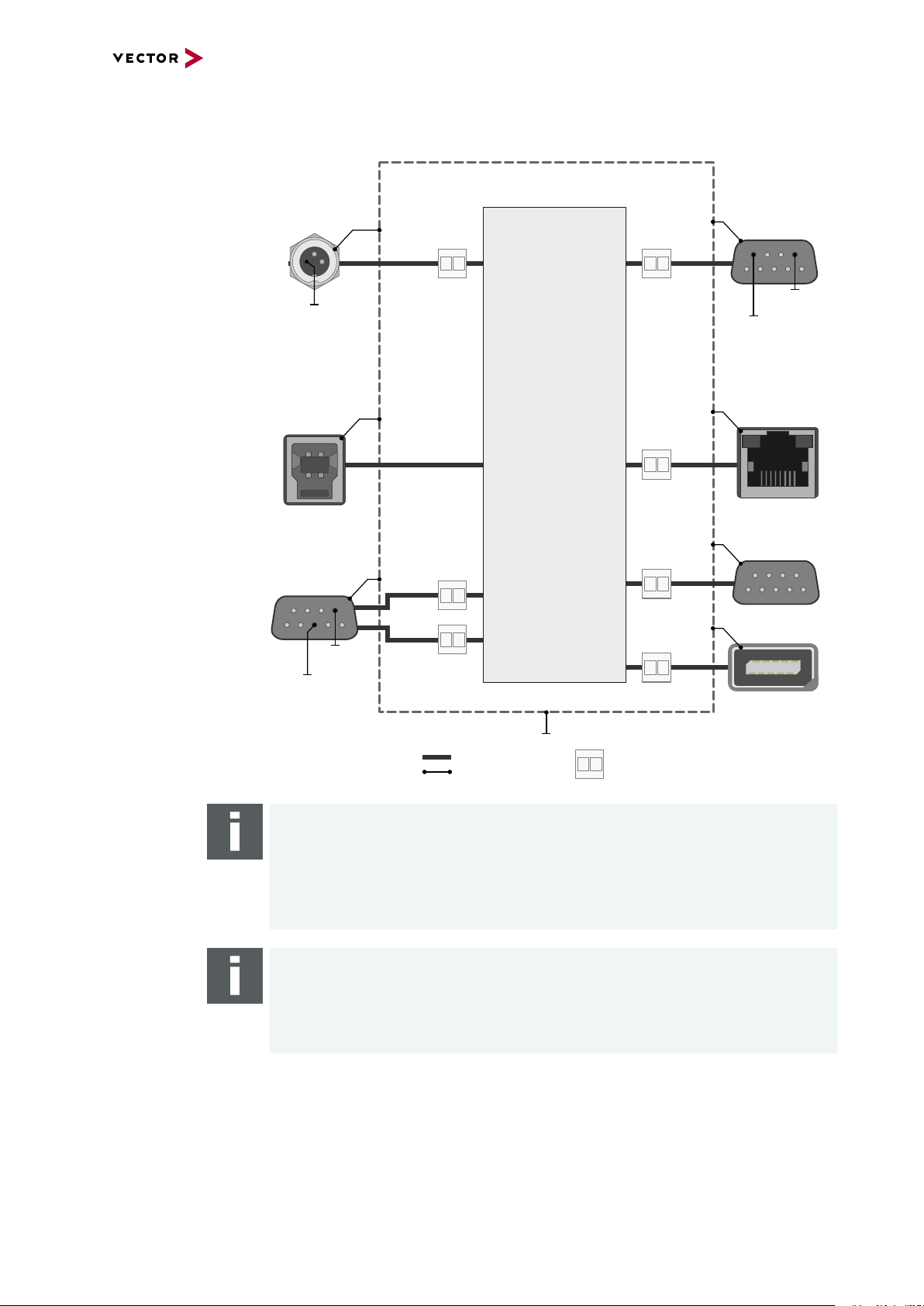
2.2 Examples of Usage
2.2.1 Transparent Ethernet Monitoring
Monitoring The VN5000 network interface can be used for Ethernet monitoring between an ECU
and a connected sensor without influencing the Ethernet bus (Test Access Point). In
this particular setup the VN5000 network interface receives and forwards incoming
data packages transparently from one port to the other. The VN5000 network interface
offers up to six TAP (Test Access Point) paths which can be used in parallel.
Setup
Figure 1: TAP Ether net data
This allows applications such as CANalyzer.Ethernet or CANoe.Ethernet to trace Ethernet data with accurate time stamps.
VN5610A Physical Layer Bypassing Latency ∆t
100BASE-T1100BASE-T1 8.1 µs
1000BASE-T1000BASE-T 1.6 µs
VN5640 Physical Layer Bypassing Latency ∆t
100BASE-T1100BASE-T1 7.7 µs
1000BASE-T11000BASE-T1 6.6 µs
VN5620 / VN5430 Physical Layer Bypassing Latency ∆t
1000BASE-T1000BASE-T 2.3 µs
100BASE-T1100BASE-T1 8.3 µs
1000BASE-T11000BASE-T1 5.7 µs
VN5000 Manual Version 2.5 15
Page 16
2 General Information
ETH Port 1
PC
CANalyzer.Ethernet/CANoe.Ethernet
ETH Port 2
Sensor
Sensor
Sensor Sensor Sensor
Sensor
CAN
VN5000
bypassing
Time Stamp Clock
USB/ETH
CAN
CH3
CAN
CH4
ECUECU
SWITCH
ECU
SWITCH
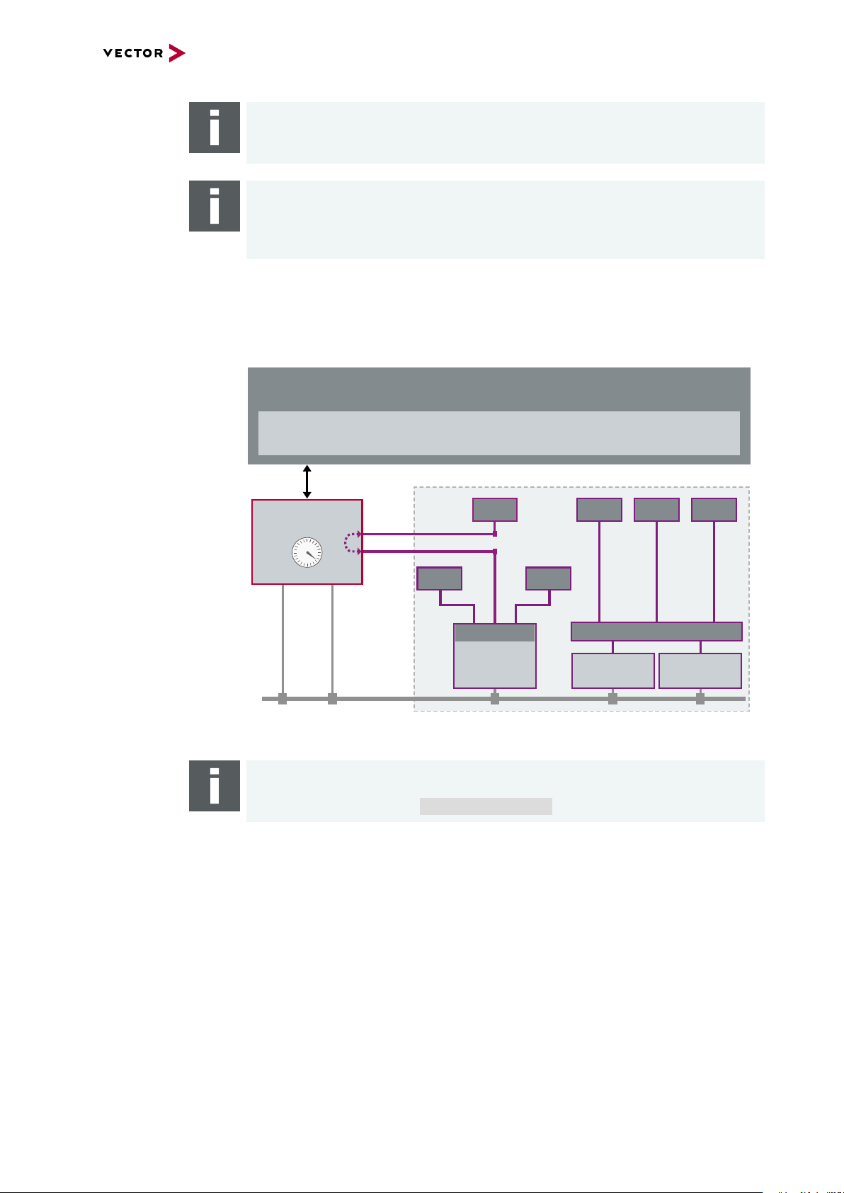
Note
The latency values depend on PHY characteristics, used MII interface and
VN5000 specific TAP handling.
Note
For a network tap, you have to connect the VN5000 interface between the ECUs.
In the event of a fault or when the VN5000 is switched off, the network connection
between the ECUs will be interrupted. This can lead to malpractice of the vehicle.
Time stamp clock for
Ethernet and CAN
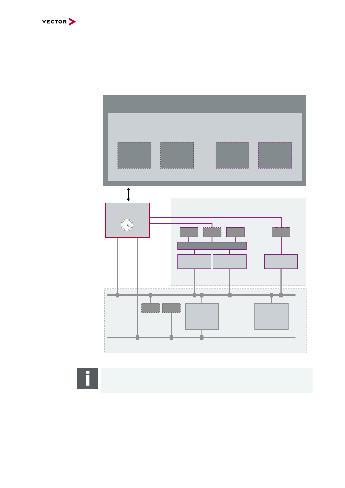
The VN5000 network interface uses a common time stamp clock for Ethernet and
CAN events. So if the measurement setup is extended by a CAN network, the generated CAN time stamps are always in sync with the Ethernet time stamps which
helps analyzing the network.
Figure 2: Extended measuring setup
Note
Additional Vector network interfaces can be synchronized by software, hardware
or IEEE 1588 (see section Time Synchronization on page 135).
VN5000 Manual Version 2.5 16
Page 17
2.2.2 Remaining Bus Simulation
PC
CANalyzer.Ethernet/CANoe.Ethernet
CAN
ECU
CAN
CH3
CAN
CH4
VN5000
Time Stamp Clock
ECUECU
Sensor
CANoe
ETH SIM #1
Sensor
SWITCH
CANoe
ETH SIM
#1
CANoe
ETH SIM
#2
CANoe
CAN SIM
#2
CANoe
CAN SIM
#1
ECU
CANoe
ETH SIM #2
CAN
Gateway
CANoe
CAN SIM #1
CANoe
CAN SIM #2
USB/ETH
ETH Port 1
ETH Port 2
2 General Information
Developing
networks
Setup
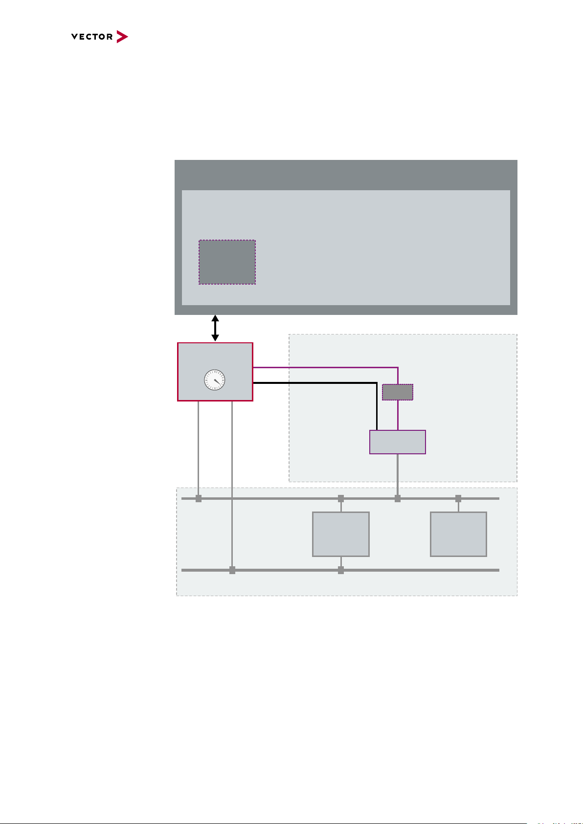
The VN5000 network interface is able to send and receive data packages on separate
Ethernet ports as well as events on two separate CAN channels. With this, the
VN5000 network interface is a perfect choice for the remaining bus simulation during
the development of complex networks.
Figure 3: Simulated nodes
Note
For the remaining bus simulation CANoe.Ethernet is required.
VN5000 Manual Version 2.5 17
Page 18
2.2.3 Standalone Media Converter
VN5000
Media Converter
PC/Standard Ethernet Logger
Port 1
Port 2
100BASE-TX
100BASE-T1
SensorSensor
ECU
SWITCH
2 General Information
Physical layer
conversion
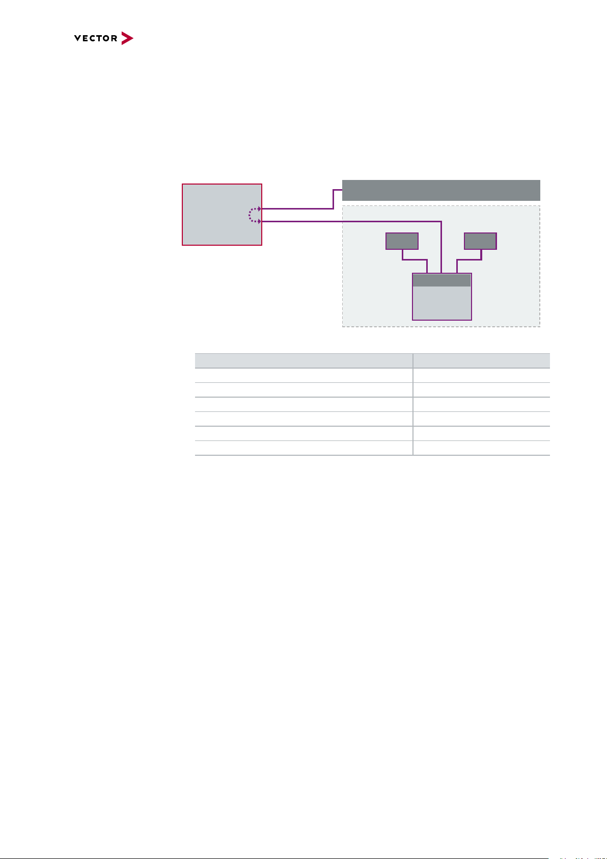
The Ethernet ports of the VN5000 network interface can be configured independently.
That way the VN5000 network interface can be used as a media converter between
an ECU using the 100BASE-T1/1000BASE-T1 Ethernet standard and any standard
Ethernet equipment (e.g. loggers) using 100BASE-TX/1000BASE-T. The VN5000 network interfaces offer up to four media converters which can be used independently.
Setup
Figure 4: Media converter
Media converter Device Count
VN5610(A) 1
VN5620 2
VN5430 1
VN5640 4
VN5240 3
VN5650 4
VN5000 Manual Version 2.5 18
Page 19
2 General Information
PC
CANalyzer.Ethernet/CANoe.Ethernet
CAN
ECU
CAN
CH3
CAN
CH4
ETH Port 1
VN5000
Time Stamp Clock
CANoe
ETH SIM
#1
ECU
CANoe
ETH SIM #1
CAN
Gateway
USB/ETH
IO
100BASE-TX
DoIP Activation
2.2.4 Diagnostics over IP
DoIP activation line For diagnostics over IP, the VN5000 network interface supports, beside the neces-
sary 100BASE-TX port, an digital IO channel which has a DoIP activation line according to the ISO specification (ISO DIS 13400-3). The activation level can be set by the
VN5000 network interface to switch the ECU to diagnostic mode.
Setup
Figure 5: Simulated nodes
VN5000 Manual Version 2.5 19
Page 20
2 General Information
ETH Port 1
VN5000
ETH Port 2
Sensor
bypassing
ECU
SWITCH
ETH Port 3
ETH Port 4
bypassing
Sensor
ECU
SWITCH
ETH Port 13
ETH
Logger
2.2.5 Port Mirroring
Note
This feature is only supported on VN5240, VN5430, VN5640 and VN5650.
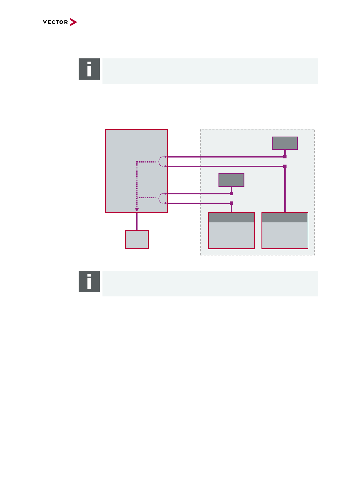
Description The VN5000 network interface supports mirroring of incoming packets of selected
source port to a specific target port. For example, this mirroring feature can be used to
attach an Ethernet logger to the target port. Additionally, the outgoing logging traffic
can be reduced by setting protocol filters.
Setup
Figure 6: Ethernet port 13 configured as target, port 1...4 as source
Note
The configuration is done in Vector Hardware Config.
VN5000 Manual Version 2.5 20
Page 21

3 VN5610A
3 VN5610A
In this chapter you find the following information:
3.1 Scope of Delivery 22
3.2 Introduction 22
3.3 Connectors Ethernet Side 24
3.3.1 Connectors USB Side 25
3.3.2 LEDs 27
3.3.3 Technical Data 28
3.4 Accessories 32
VN5000 Manual Version 2.5 21
Page 22
3.1 Scope of Delivery
Contents The delivery includes:
► VN5610(A) Ethernet/CAN interface
► Vector Power Supply 12 V / 1.25 A (part number 05024)
► USB 2.0 cable (part number 05011)
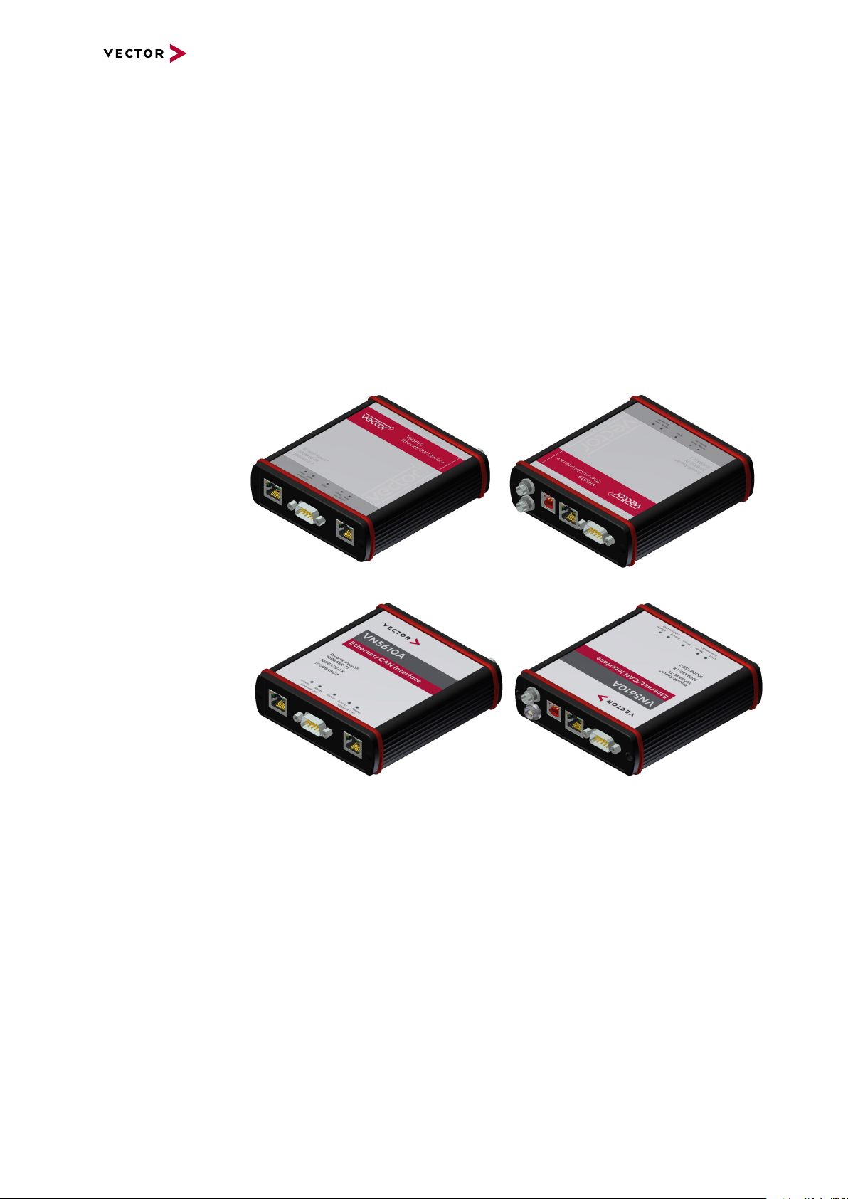
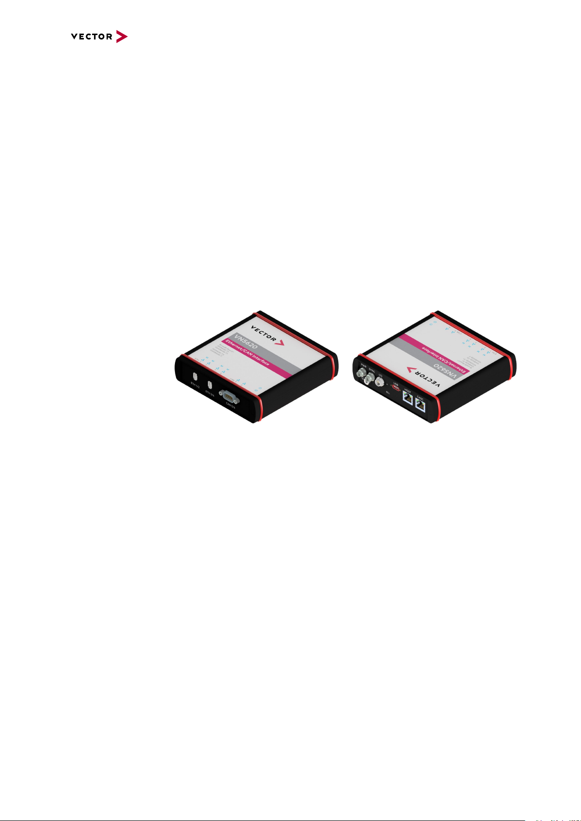
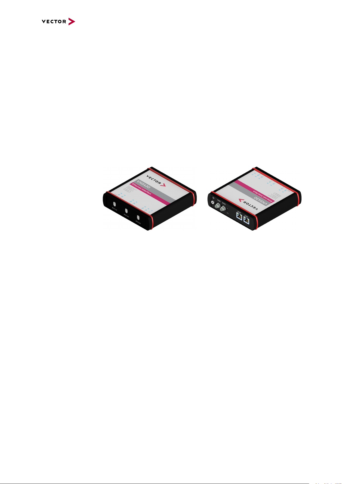
3.2 Introduction
3 VN5610A
About the
VN5610(A)
The VN5610(A) is a Vector network interface which supports the Ethernet physical
layer 10BASE-T, 100BASE-T1 (OPEN Alliance BroadR-Reach), 100BASE-TX and
1000BASE-T. 100BASE-T1 is a physical layer especially used in automotive electronics.
Figure 7: VN5610 Ethernet/CAN Interface
Figure 8: VN5610A Ethernet/CAN Interface
The VN5610(A) enables the transparent monitoring and logging of Ethernet data
streams and CAN events with minimal latency times and high resolution time
stamps.With this, the VN5610(A) enables a variety of applications such as simple
bus analyses, complex remaining bus simulations as well as diagnostic and calibration (e.g. with CANalyzer.Ethernet/CANoe.Ethernet).
Highlights Common features of VN5610 and VN5610A:
► Support of two independent Ethernet ports,
available as 2x RJ45 or 1x D-SUB9
► Support of standard Ethernet (10BASE-T/100BASE-TX/1000BASE-T)
► Support of two independent CAN/CAN FD channels,
available as 1x D-SUB9
► High resolution time stamps for Ethernet frames
VN5000 Manual Version 2.5 22
Page 23

► High resolution time stamps for CAN/CAN FD frames
► Software, hardware and IEEE 1588 time synchronization
of multiple Vector network interfaces
► Internal three-way-routing in/monitor/out
► Robustness, power supply and temperature ranges
suitable for automotive and industrial applications
Differences Differences between VN5610 and VN5610A:
VN5610
► Support of BroadR-Reach physical layer
VN5610A
► Support of 100BASE-T1 (OPEN Alliance BroadR-Reach)
► Support of one digital input/output (e.g. for DoIP Activation Line)
3 VN5610A
VN5000 Manual Version 2.5 23
Page 24
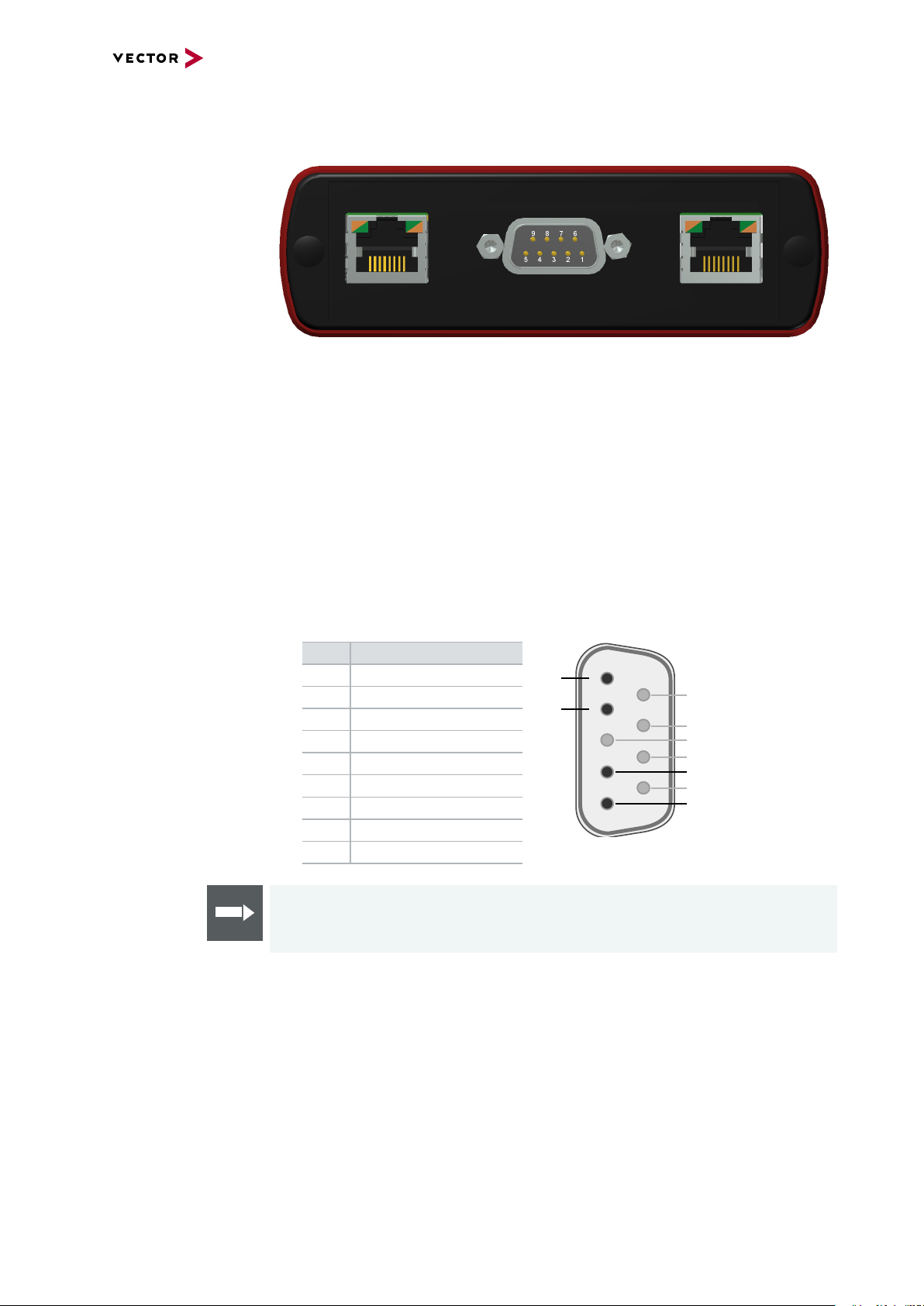
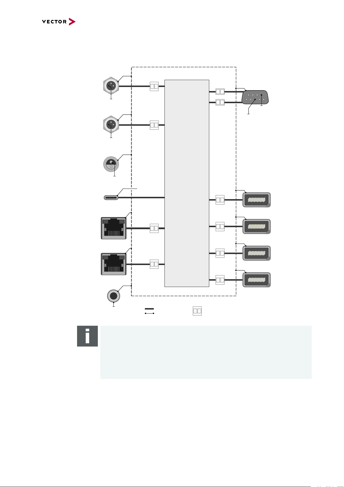
3.3 Connectors Ethernet Side
ACT SPEED ACT SPEED
5
4
3
2
1
6
7
8
9
N
P
Not connected
Not connected
Not connected
Not connected
P
N
Not connected
Port 1 Port 2
Device connectors
Figure 9: Ethernet CH1, D- SUB9 (100BASE-T1), Ethernet CH2
3 VN5610A
► Ethernet CH1/CH2 (RJ45)
Standard Ethernet connector for
10BASE-T, 100BASE-TX and
LED ACT
- Illuminates if there is an Ethernet link.
- Blinks if there is Ethernet activity.
1000BASE-T.
LED SPEED
- Off: 10 Mbit
- Orange: 100 Mbit
- Green: 1000 Mbit
► Ethernet CH1/CH2 (D-SUB9)
D-SUB9 connector for 100BASE-T1. Use the BRcable 2Y to access both ports
on separate D-SUB9 connectors (see accessories manual, part number 05103).
Pin Assignment
1 CH2 P
2 CH2 N
3 Not connected
4 CH1 P
5 CH1 N
6 Not connected
7 Not connected
8 Not connected
9 Not connected
VN5000 Manual Version 2.5 24
Reference
The Ethernet configuration must be done in Vector Hardware Config.
Page 25
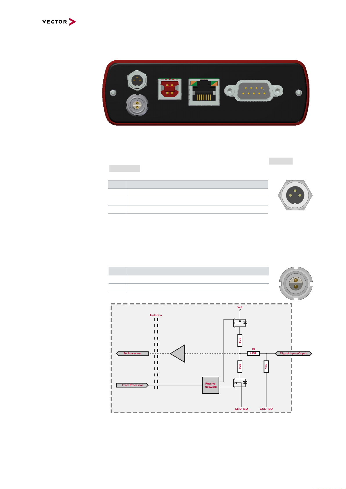
3.3.1 Connectors USB Side
ACT SPEED
3 1
2
1
2
Digital Input/Ouput
Isolation
455R
Ri
50R
50R
Vcc
GND_ISO
Passive
Network
From Processor
To Processor
GND_ISO
10k
Device connectors
Figure 10: Connectors on the USBside
► Power/sync (Binder connector)
The VN5610A has one power/sync connector (Binder type 711) which can be used
for time synchronization of different Vector devices (see section Time Synchronization on page 135) or for power.
Pin Assignment
1 Power supply (6 V … 50 V DC, typ. 12 V)
2 Synchronization line
3 Ground
3 VN5610A
► IO CH5 (Lemo connector)
The VN5610A has a Lemo connector (type 302) for dedicated digital input/output
tasks (e.g. as DoIP Activation Line). Use the VX1362B adapter cable to access
the pins (see accessories manual, part number 22258). The pin assignment is as
follows:
Pin Assignment
1 Digital input/output (see technical data)
2 Ground
Figure 11: Digital input /output
VN5000 Manual Version 2.5 25
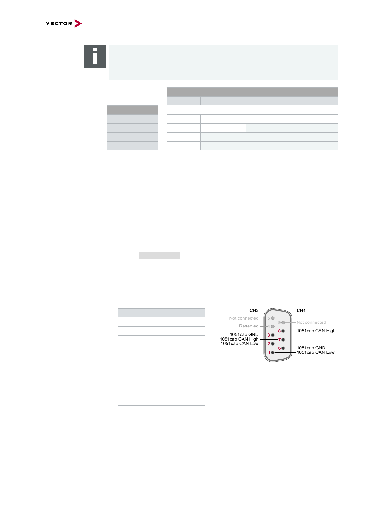
Page 26
3 VN5610A
5
4
3
2
1
6
789
Not connected
Reserved
1051cap CAN High
1051cap GND
1051cap CAN Low
1051cap CAN Low
1051cap GND
1051cap CAN High
CH3
CH4
Not connected
Note
The VN5610A requires at least 8 V to power up. Afterwards the power supply can
be reduced to 6 V for operation (typ. 12 V DC). The need of an external power supply depends on the Ethernet configuration (see table).
Ethernet
Configuration
Disabled 100BASE-T1 100BASE-TX 1000BASE-T
Port 1
Port 2
Disabled O O O O
100BASE-T1 O O X X
100BASE-TX O X X X
1000BASE-T O X X X
O: bus-powered (also when both CAN channels in use), X: external power supply recommended.
Note: CAN itself requires no external power supply.
► USB
Connect your PC and the VN5610A over USB to install and to use the device with
measurement applications (CANoe, CANalyzer). Use the USB 2.0 compliant
cable found in the delivery (USB extension cables may generate faults between
the PC and the device). Connect the device directly to a USB port at your PC or
use a USB hub with its own power supply (self-powered). The device can also be
powered via this connector.
► Host (Ethernet)
Alternative host connection over Ethernet (1000BASE-T). For configuration, see
section Getting Started on page 154.
► CAN CH3/4 (D-SUB9)
D-SUB connector with two CAN channels. Use the CANcable 2Y to access both
channels on separate D-SUB9 connectors (see accessories manual, part number
05075).
Pin Assignment
1 CH4 CAN Low
2 CH3 CAN Low
3 CH3 GND
4 Reserved.
Please do not use.
5 Not connected
6 CH4 GND
7 CH3 CAN High
8 CH4 CAN High
9 Not connected
VN5000 Manual Version 2.5 26
Page 27

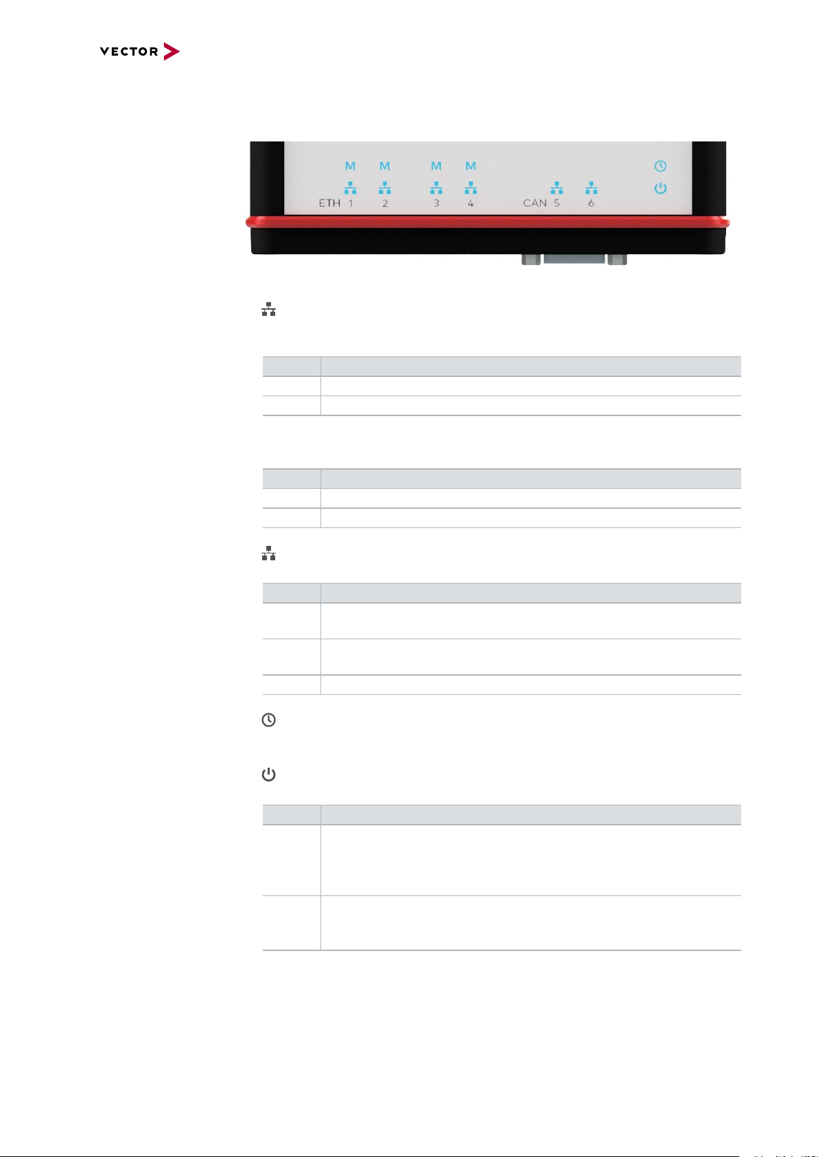
3.3.2 LEDs
LEDs on top side
3 VN5610A
Figure 12: LEDs on VN5610(A)
► Activity (Ethernet CH1/CH2)
Same as LED ACT at RJ45 connectors. LED illuminates if there is an Ethernet
link or blinks if there is Ethernet activity at CH1/CH2.
Color Description
Green Link to RJ45.
Yellow Link to D-SUB9.
► Master (Ethernet CH1/CH2)
Illuminates if CH1/CH2 is configured as Master.
Color Description
Green PHY is configured as master on RJ45.
Yellow PHY is configured as master on D-SUB9.
► Status
Multicolored LED indicating the device status.
Color Description
Green Blinks 4x at power up and illuminates afterwards.
Blinks quicker during an update progress. Please wait for the automatic reboot of the device (approx. 30 s) after the update has been finished.
Red An error has occurred. Please disconnect the power supply as well as
the USB cable. Re-connect the power supply and the USB cable and
try again.
VN5000 Manual Version 2.5 27
Page 28

3.3.3 Technical Data
3.3.3.1 Overview
Ethernet ports Max. 2, selectable from:
CAN/CAN FD channels Max. 2
Digital input/output 1x Lemo
3 VN5610A
2x RJ45
10BASE-T, 100BASE-TX, 1000BASE-T
(on-board BCM54810 PHY)
1x D-SUB9 for 100BASE-T1
(OPEN Alliance BroadR-Reach; dual port)
(on-board BCM89811 PHY)
(on-board TJA1051 transceivers)
1x D-SUB9 (dual channel)
CAN2.0: 2 MBit/s
CAN FD: up to 8 MBit/s
Push/pull mode (e.g. DoIP Activation Line)
or only Push mode (e.g. Wake-up Triggers)
Output high (no load): 13V
Output high (load 346Ω): 5.3V
Output low: 0V
Input range: 0V…16V
Input: Schmitt trigger high 3.4V
Input: Schmitt trigger low 2.5V
Rout: 503Ω
PC interface USB 2.0 or Ethernet (1000BASE-T)
Power supply Without external power supply:
bus-powered at 100 Mbit operation mode
With external power supply:
6…50 V DC, typ. 12 V DC,
power-up: 8 V DC
Power consumption Approx. 2.5 W
Time stamps Resolution: 8 ns
Accuracy (in device): 1 µs
Accuracy software sync: typ. 50 µs
Accuracy hardware sync: typ. 1 µs
Accuracy PTP sync (IEEE1588): typ. 1µs
Temperature range Operation: -40 °C ... +65 °C
Storage: -40 °C ... +85 °C
Relative humidity
of ambient air
Dimensions (LxWxH) Approx. 125 mm x 106 mm x 32 mm
Operating system requirements Windows 7 SP1 (32 bit / 64 bit)
15 %...95 %, non-condensing
Windows 8.1 (32 bit / 64 bit)
Windows 10 (64 bit)
VN5000 Manual Version 2.5 28
Page 29
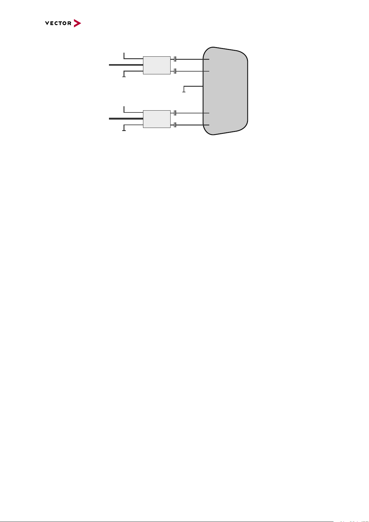
3.3.3.2 Electrical Isolation
Power/
Sync
USB
Case
Ethernet
Port 1
5
9 8 7 6
4 3 2 1
100BASE-T1
Ethernet
Port 2
Logic
12345
6789
CAN
Channel 3/4
GND
ISO1
GND ISO
GND
GND
ISO2
GND
Ethernet
Host
3 1
2
GND ISO_SYNC
Electrical
Isolation
Supply/Data
Connected
Shield
Shield
Shield
Shield
Shield
Shield
Shield
CH3
CH4
1
2
7
2
3
7
8
2
1
3
6
D-SUB9
CAN High
Power
Ground
Ground
CAN Low
CAN GND
TJA1051
Signal isolator
DC/DC
CAN High
Power
Ground
Ground
CHA
CHB
CAN Low
CAN GND
TJA1051
Signal isolator
DC/DC
Electrical isolation
of the connectors
3 VN5610A
Electrical isolation
of CAN in detail
VN5000 Manual Version 2.5 29
Page 30
Electrical isolation
4
5
1
2
D-SUB9
Ethernet P
Power
Power
GND
GND
MII A
MII B
Ethernet N
GND
Shield
BMC89811
BMC89811
Ethernet P
CHA
CHB
Ethernet N
of Ethernet in detail
3 VN5610A
VN5000 Manual Version 2.5 30
Page 31

3.3.3.3 Network Features
3 VN5610A
Ports/channels
1000BASE-T1 100BASE-T1 2
10/100/1000BASE-T(X) 2
1, 2.5, 5, 10G BASE-T CAN-FD 2
DoIP Activation / Wake-up Line X
Multiple digital / analog IO -
Device sync Hardware synchronization X
Software synchronization X
IEEE1588 (PTP) X
Infrastructure PC uplink USB2.0 / 1000BASE-T
Power supply Ext. power supply /
USB buspowered
Application area Measurement / analysis X
Simulation X
Test X
Port interconnection Layer 2 Switch X
TAP X
Media conversion 1
Link transparency X
OPEN Alliance TC10 (Wake/Sleep) Physical bypass relays Ports interconnectable at the same time 2
Measure Mirroring port -
Uplink frame filter 16 rules
Error frame reporting X
VLAN tagging / untagging / routing Virtual ports 16
Test Onboard packet generator X
Error frame generation X
OPEN Alliance TC10 (Wake/Sleep) -
1)
available in a later release
VN5000 Manual Version 2.5 31
Page 32

3.4 Accessories
Note
Detailed information on the listed accessories can be found in the separate
accessories manual on our website.
3 VN5610A
Cables and
connectors
Power supply ► Vector Power Supply 12V/1.5A
► BRcable 2Y
► VNcable D-SUB9 HSD Z
► CANcable1
► CANcableA
► CANcable TnT
► CANcable Y
► CANcable 2Y
► CANterm 120
► CANcable Set Pro
► SYNCcableXL
► SYNCcable50
► Multi SYNCbox external
► Multi SYNCbox internal
► Multi SYNCbox active
► Connection Cable Binder Type 711
► Cable Lemo/Banana Plugs
► USB Cable 2.0
► Banana Plug <> Binder 3-Pin
► Car Power Supply Cable 12V with Binder
Miscellaneous ► Fix Kit 32mm Device
VN5000 Manual Version 2.5 32
Page 33

4 VN5620
4 VN5620
In this chapter you find the following information:
4.1 Scope of Delivery 34
4.2 Introduction 34
4.3 Connectors 36
4.3.1 Front Side 36
4.3.2 Back Side 38
4.4 LEDs 40
4.5 Technical Data 41
4.5.1 Overview 41
4.5.2 Temperature Shutdown 41
4.5.3 Electrical Isolation 43
4.5.4 Network Features 45
4.6 Accessories 46
VN5000 Manual Version 2.5 33
Page 34
4 VN5620
4.1 Scope of Delivery
Contents The delivery includes:
► 1x VN5620 Ethernet/CAN Interface
► 1x USB cable 3.0 (A-C, 1. 8m, with screws)
► 1x USB cable 3.0 (C-C, 1. 8m, with screws)
► 1x Vector power supply 12 V / 1.25 A (part number 05024)
4.2 Introduction
About the VN5620 The VN5620 is a compact and powerful interface for the analysis, simulation, test and
validation of Ethernet networks. The VN5620 interface supports a wide range of possible applications. It is suitable for synchronous Ethernet monitoring with other bus
systems, network participation (e.g. in simulations and generation of frames, loads
and errors in tests). The user can use Ethernet (1000BASE-T) or USB 3.0 as interface
to the computer.
Figure 13: VN5620 Ethernet/CAN Interface
Highlights Features of the VN5620:
► 4x user port IEEE 100BASE-T1 / 1000BASE-T1
► 2x user channel CAN FD
► 1x digital IO (e.g. for DoIP ActivationLine)
► 2x infrastructure port, standard Ethernet (100BASE-TX / 1000BASE-T),
usable as:
- uplink to host PC
- an alternative user port
(e.g. to analyze traffic of a 100BASE-TX/10000BASE-T link)
► Host connection via USB 3.0 or Ethernet
► Onboard Ethernet TAPs to link between two Ethernet ports
► Onboard Vector Ethernet Switch IP
► New hardware configuration concept
► Usable without host-connection to interconnect ECUs
- Self-configuration after power-up
► Hardware filtering of Ethernet packets on protocol base
► Device synchronization to other Vector interfaces or 3rd party via
- software synchronization (typ. 50µs accuracy)
- hardware synchronization (1µs accuracy)
► Multi-application support (different tools can share an Ethernet port at the same
time)
VN5000 Manual Version 2.5 34
Page 35

4 VN5620
► Support of 3rd party tools with free XL Driver Library (planned in a later release)
► Provides high precision time stamped Ethernet/CAN frames (< 20 ns precision)
VN5000 Manual Version 2.5 35
Page 36

4.3 Connectors
12345
109876
4.3.1 Front Side
Device connectors
Figure 14: Connectors on the Ethernet side
► Ethernet 1/2 and 3/4 (ix Industrial)
ix Industrial connectors for 100BASE-T1/1000BASE-T1 (e.g. Harting ix Industrial
type 10A-1). Each connector has two Ethernet ports (A and B). Use cables of the
Vector AEcable 2Y family to access both ports on separate connectors (different
plug systems available)
4 VN5620
Pin Assignment
1 CH2 P
2 CH2 N
3 Not connected
4 Not connected
5 Not connected
6 CH1 P
7 CH1 N
8 Not connected
9 Not connected
10 Not connected
Note
We recommend the usage of an AEcable 2Y (see section Accessories on page
46), because it separates the VN5620 shield potential from the ECU shield potential. This ensures that all compensating currents over the shields are avoided. A
capacitive coupling of the shields is implemented in the AEcable 2Y.
VN5000 Manual Version 2.5 36
Page 37

4 VN5620
5
4
3
2
1
6
789
Not connected
Reserved
1051cap CAN High
1051cap GND
1051cap CAN Low
1051cap CAN Low
1051cap GND
1051cap CAN High
Not connected
CH17
CH18
► CAN 5/6 (D-SUB9)
D-SUB9 connector for CAN. The connector has two channels. Use the CANcable
2Y to access both channels on separate D-SUB9 connectors (see accessories
manual, part number 05075)
Pin Assignment
1 CH18 CAN Low
2 CH17 CAN Low
3 CH17 GND
4 Reserved.
Do not use.
5 Not connected
6 CH18 GND
7 CH17 CAN High
8 CH18 CAN High
9 Not connected
VN5000 Manual Version 2.5 37
Page 38

4.3.2 Back Side
3 1
2
3 1
2
1
2
Device connectors
4 VN5620
Figure 15: Connectors on the USB side
► Power (Binder)
Use this connector to power the VN5620 as alternative to USB-C (see USB connector details).
Pin Assignment
1 Power supply 10 V...18V (typ. 12VDC)
2 Not connected
3 Ground
► Sync (Binder)
The VN5620 has one sync connector (Binder type 711) which can be used for time
synchronization of different Vector devices (see section Time Synchronization on
page 135).
Pin Assignment
1 Not connected
2 Synchronization line
3 Ground
► Reset
If the device configuration is corrupted, start it with pushed reset button.
► I/O (Lemo connector)
Lemo connector (type 302) for bidirectional digital input/output.
Pin Assignment
1 Digital IO
2 Ground
► USB (Type-C)
Connect your PC and the VN5620 via USB to install and to use the device
with measurement applications (e. g. CANoe, CANalyzer). If the host PC
provides a current of 3A, the device can also be powered via this connector.
► Host (RJ45 connector)
Connect your PC and the VN5620 via RJ45 to use the device with measurement applications (e. g. CANoe, CANalyzer) in a network setup.
VN5000 Manual Version 2.5 38
Page 39

► Casc (RJ45 connector)
Infrastructure port with different possible configurations:
- alternative analysis port
► Functional Earth (FE)
Optional connection of housing ground to system ground.
► Kensington Lock
Mounting of Nano Kensington (NanoSaver).
4 VN5620
VN5000 Manual Version 2.5 39
Page 40
4.4 LEDs
LEDs
4 VN5620
Figure 16: Top LEDs on VN5620
► Ethernet Port 1...4
LED illuminates if there is an Ethernet link or blinks if there is Ethernet activity at
the according port.
Color Description
Green 1000MBit.
Orange 100MBit.
►MEthernet Port 1...4
Illuminates if the according port is configured as master.
State Description
On PHY is configured as master.
Off PHY is configured as slave.
► CAN (CH5/CH6)
Multicolored channel LEDs, each indicating the bus activity for CAN.
Color Description
Green Data frames have been sent or received correctly.
The flashing frequency varies according to the message rate.
Orange Error frames have been sent or received.
The flashing frequency varies according to the message rate.
Red Bus off.
► Sync
LED illuminates if the device is synchronized.
► Power
Multicolored LED indicating the device status.
Color Description
Green Blinks 4x at power up and illuminates afterwards.
Blinks quicker during an update progress. Please wait for the automatic reboot of the device (approx. 60 seconds) after the update has
been finished.
Red An error has occurred. Please disconnect the power supply as well as
the USB cable. Re-connect the power supply and the USB cable and
try again.
VN5000 Manual Version 2.5 40
Page 41

4.5 Technical Data
4.5.1 Overview
Ethernet ports 4x Marvell 88Q2112-A2
CAN/CAN FD channels 2x NXP TJA1057
Digital input/output Output high (no load): 13V
PC interface USB 3.0 / IEEE 1000BASE-T
Input voltage External powered 10...18V (typ. 12VDC) or
Power consumption Max. 15W
Time stamps Resolution: 15.625 ns
Temperature range
(ambient temp. of the device)
Relative humidity
of ambient air
Dimensions (LxWxH) 143mm x 153mm x 37mm
Weight 570g
Operating system requirements Windows 10 (64 bit)
4 VN5620
(IEEE 100BASE-T1/ 1000BASE-T1)
2x Broadcom BCM54210
(IEEE 1000BASE-T)
Output high (load 346Ohm): 5.3V
Output low: 0V
Input range: 0...16V
Input Schmitt trigger high: 3.4V
Input Schmitt trigger low: 2.5V
Rout: 503 Ohm
USB-C powered (must support USB-C, 3
ampere)
Accuracy (in device): 1 µs
Accuracy software sync: typ. 50 µs
Accuracy hardware sync: typ. 1 µs
Operation: -25°C ... +60°C
Storage: -40 °C ... +85 °C
15 %...95 %, non-condensing
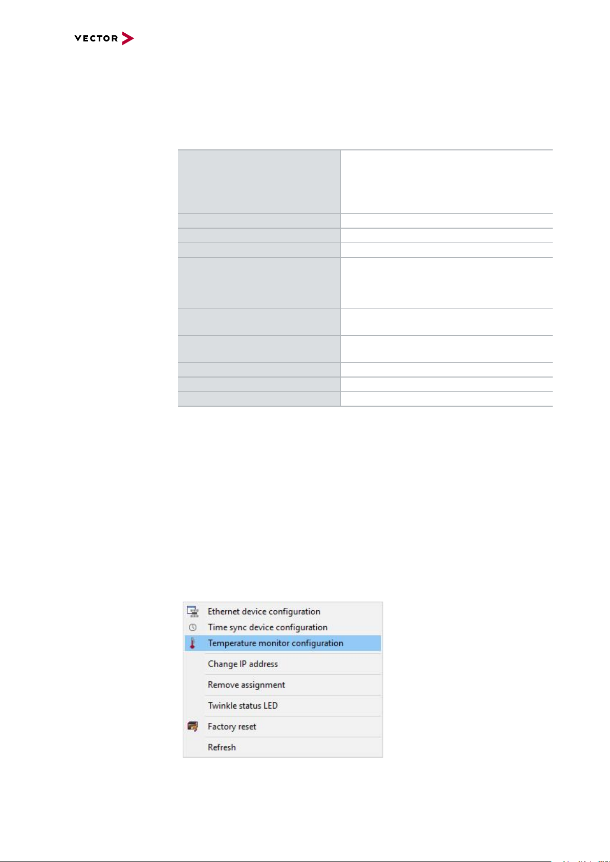
4.5.2 Temperature Shutdown
Temperature
limits
VN5000 Manual Version 2.5 41
The units are temperature monitored to prevent damage to the unit. The devices
switch off automatically when the upper limit temperature is exceeded. This limit
value represents the theoretical maximum of the hardware. However, it is possible to
leave this range slightly without damaging the hardware.
For this purpose the temperature shutdown can be switched off actively.
If the maximum temperature is exceeded, it is indicated by a red status LED on the
device. Vector applications also display this (e.g. in the Write window of CANoe).
You can find the settings in the Vector Hardware Config tool.
Page 42

Figure 17: Open configuration
4 VN5620
Figure 18: Setting limit for shutdown
VN5000 Manual Version 2.5 42
Page 43
4.5.3 Electrical Isolation
Case
Supply/Data
Connected
Electrical
Isolation
Power
Sync
I/O
USB-C
Shield
Shield
Shield
Shield
Shield
GND
GND
EXT
GND
ISO_CH6
GND
ISO_CH5
CH5
CH6
GND
ISO_SYNC
331
1
2
2
Ethernet
Host
Ethernet
Casc
FE
Shield
12345
109876
Ethernet
Port 1
Shield
CAN
5...6
Shield
12345
109876
Ethernet
Port 2
Shield
12345
109876
Ethernet
Port 3
Shield
12345
109876
Ethernet
Port 4
Logic
35 4 2 1
89 7 6
1
2
Shield
GND
ISO_IO
Electrical isolation
of the connectors
4 VN5620
Note
Please note that the shield of the USB-C connector is the same potential as the
logic GND and that it is isolated from the case shield. This is intended to avoid
ground loops when using a 12V notebook power supply without electrical isolation.
The FE plug must be connected to the chassis ground if the network interface is
used in a vehicle with shieled cables.
VN5000 Manual Version 2.5 43
Page 44

Electrical isolation
7
2
3
7
2
3
8
1
6
D-SUB9
CAN High
Power
Ground
Ground
CAN Low
CAN GND
TJA1057
Signal isolator
DC/DC
CAN High
Power
Ground
Ground
CHA
CHB
CAN Low
CAN GND
TJA1057
Signal isolator
DC/DC
5
6
1
2
iX
Ethernet P
Power
Power
GND
GND
MII A
MII B
Ethernet N
FE
Shield
88Q2112
88Q2112
Ethernet P
CHA
CHB
Ethernet N
of CAN in detail
4 VN5620
Note
The usage of an AEcable 2Y is recommended because it separates the interface's
shield potential from the ECU shield potential. This ensures that all compensating
currents over the shields are avoided. A capacitive coupling of the shields is implemented in the AEcable 2Y.
Electrical isolation
of Ethernet in detail
VN5000 Manual Version 2.5 44
Page 45

4.5.4 Network Features
4 VN5620
Ports/channels
1000BASE-T1 / 100BASE-T1 4
10/100/1000BASE-T(X) 2
1, 2.5, 5, 10G BASE-T CAN-FD 2
DoIP Activation / Wake-up Line X
Multiple digital / analog IO -
Device sync Hardware synchronization X
Software synchronization X
IEEE1588 (PTP) X
1)
Infrastructure PC uplink USB3.0 / 1000BASE-T
Power supply Ext. power supply /
USB buspowered
Application area Measurement / analysis X
Simulation X
Test X
Port interconnection Layer 2 Switch X
TAP X
Media conversion 2
Link transparency X
OPEN Alliance TC10 (Wake/Sleep) Physical bypass relays Ports interconnectable at the same time 4
Measure Mirroring port -
Uplink frame filter 16 rules
Error frame reporting X
VLAN tagging / untagging / routing X
Virtual ports 32
Test Onboard packet generator X
Error frame generation X
OPEN Alliance TC10 (Wake/Sleep) -
1)
available in a later release
VN5000 Manual Version 2.5 45
Page 46

4.6 Accessories
Note
Detailed information on the listed accessories can be found in the separate
accessories manual on our website.
4 VN5620
Cables and
connectors
► AEcable 2Y
► Ethernetcables
► CANcable1
► CANcableA
► CANcable TnT
► CANcable Y
► CANcable 2Y
► CANterm 120
► CANcable Set Pro
► SYNCcableXL
► SYNCcable50
► Multi SYNCbox external
► Multi SYNCbox internal
► Multi SYNCbox active
► Connection Cable Binder Type 711
► Cable Lemo/Banana Plugs
► USB Cable 3.1 Type A-C (Dual Screw Lock)
► USB Cable 3.1 Type C-C (Dual Screw Lock)
Power supply ► Vector Power Supply 12V/1.5A
► Banana Plug <> Binder 3-Pin
Miscellaneous ► Fix Kit 32mm Device
VN5000 Manual Version 2.5 46
Page 47

5 VN5430
5 VN5430
In this chapter you find the following information:
5.1 Scope of Delivery 48
5.2 Introduction 48
5.3 Connectors 49
5.3.1 Front Side 49
5.3.2 Back Side 50
5.4 LEDs 51
5.5 Technical Data 52
5.5.1 Overview 52
5.5.2 Temperature Shutdown 52
5.5.3 Electrical Isolation 53
5.5.4 Network Features 55
5.6 Accessories 56
VN5000 Manual Version 2.5 47
Page 48
5 VN5430
5.1 Scope of Delivery
Contents The delivery includes:
► 1x VN5430 Ethernet Interface
► 1x Ethernet cable CAT6A (2m)
► 1x Vector power supply 12 V / 1.25 A (part number 05024)
5.2 Introduction
About the VN5430 The VN5430 is a compact interface for simulation and test tasks for Ethernet. The
user benefits from the VN5430‘s versatile configuration options. A wide range of simulation and test scenarios can be implemented and the network topology can be maintained at the same time. The device can also be used as a stand-alone switch.
Ethernet (1000BASE-T) is used as the interface to the computer.
Figure 19: VN5430 Ethernet Interface
Highlights Features of the VN5430:
► 6x user port IEEE 100BASE-T1 / 1000BASE-T1
► 2x infrastructure port, standard Ethernet (100BASE-TX / 1000BASE-T),
usable as:
- uplink to host PC
- an alternative user port
(e.g. to analyze traffic of a 100BASE-TX / 10000BASE-T link)
► Host connection via Ethernet
► Onboard Ethernet TAPs to link between two Ethernet ports
► Onboard Vector Ethernet Switch IP
► New hardware configuration concept
► Usable without host-connection to interconnect ECUs
- Self-configuration after power-up
► Hardware filtering of Ethernet packets on protocol base
► Device synchronization to other Vector interfaces or 3rd party via
- software synchronization (typ. 50µs accuracy)
- hardware synchronization (1µs accuracy)
► Multi-application support (different tools can share an Ethernet port at the same
time)
► Support of 3rd party tools with free XL Driver Library (planned in a later release)
► Provides high precision time stamped Ethernet frames (< 20 ns precision)
VN5000 Manual Version 2.5 48
Page 49

5.3 Connectors
12345
109876
5.3.1 Front Side
Device connectors
Figure 20: Connectors on the Ethernet side
► Ethernet 1...6 (ix Industrial)
ix Industrial connectors for 100BASE-T1/ 1000BASE-T1 (e.g. Harting ix Industrial
type 10A-1). Each connector has two Ethernet ports (A and B). Use cables of the
Vector AEcable 2Y family to access both ports on separate connectors (different
plug systems available).
5 VN5430
Pin Assignment
1 CH2 P
2 CH2 N
3 Not connected
4 Not connected
5 Not connected
6 CH1 P
7 CH1 N
8 Not connected
9 Not connected
10 Not connected
Note
We recommend the usage of an AEcable 2Y (see section Accessories on page 56)
because it separates the VN5430 shield potential from the ECU shield potential.
This ensures that all compensating currents over the shields are avoided. A capacitive coupling of the shields is implemented in the AEcable 2Y.
Note
In order to change the device configuration (link type, connection speed), you must
use the configuration tool Vector Hardware Config.
VN5000 Manual Version 2.5 49
Page 50

5.3.2 Back Side
3 1
2
3 1
2
Device connectors
5 VN5430
Figure 21: Connectors on the USB side
► Functional Earth (FE)
Optional connection of housing ground to system ground.
► Power (Binder)
Use this connector to power the VN5430.
Pin Assignment
1 Power supply 10 V...18V (typ. 12VDC)
2 Not connected
3 Ground
► Sync (Binder)
The VN5430 has one sync connector (Binder type 711) which can be used for time
synchronization of different Vector devices (see section Time Synchronization on
page 135).
Pin Assignment
1 Not connected
2 Synchronization line
3 Ground
► Reset
If the device configuration is corrupted, start it with pushed reset button.
► Host (RJ45 connector)
Connect your PC and the VN5430 via RJ45 (100BASE-TX/1000BASE-T) to
use the device with measurement applications (e. g. CANoe, CANalyzer) in a
network setup.
► Casc (RJ45 connector)
Infrastructure port with different possible configurations:
- mirror port
- alternative analysis port
► Kensington Lock
Mounting of Nano Kensington (NanoSaver).
VN5000 Manual Version 2.5 50
Page 51

5.4 LEDs
LEDs
5 VN5430
Figure 22: Top LEDs on VN5430
► Ethernet Port 1...6
LED illuminates if there is an Ethernet link or blinks if there is Ethernet activity at
the according port.
Color Description
Green 1000MBit.
Orange 100MBit.
►MEthernet Port 1...6
Illuminates if the according port is configured as master.
State Description
On PHY is configured as master.
Off PHY is configured as slave.
► Sync
LED illuminates if the device is synchronized.
► Power
Multicolored LED indicating the device status.
Color Description
Green Blinks 4x at power up and illuminates afterwards.
Blinks quicker during an update progress. Please wait for the automatic reboot of the device (approx. 60 seconds) after the update has
been finished.
Red An error has occurred. Please disconnect the power supply as well as
the USB cable. Re-connect the power supply and the USB cable and
try again.
VN5000 Manual Version 2.5 51
Page 52
5.5 Technical Data
5.5.1 Overview
Ethernet ports 6x Marvell 88Q2112-A2
PC interface IEEE 1000BASE-T
Input voltage External powered: 10 ...18V (typ. 12VDC)
Power consumption Max. 15W
Time stamps Resolution: 15.625 ns
Temperature range
(ambient temp. of the device)
Relative humidity
of ambient air
Dimensions (LxWxH) 143mm x 149mm x 37mm
Weight 554g
Operating system requirements Windows 10 (64 bit)
5 VN5430
(IEEE 100BASE-T1/ 1000BASE-T1)
2x Broadcom BCM54210
(IEEE 1000BASE-T)
Accuracy (in device): 1 µs
Accuracy software sync: typ. 50 µs
Accuracy hardware sync: typ. 1 µs
Operation: -25°C ... +60°C
Storage: -40 °C ... +85 °C
15 %...95 %, non-condensing
5.5.2 Temperature Shutdown
Temperature
limits
The units are temperature monitored to prevent damage to the unit. The devices
switch off automatically when the upper limit temperature is exceeded. This limit
value represents the theoretical maximum of the hardware. However, it is possible to
leave this range slightly without damaging the hardware.
For this purpose the temperature shutdown can be switched off actively.
If the maximum temperature is exceeded, it is indicated by a red status LED on the
device. Vector applications also display this (e.g. in the Write window of CANoe).
You can find the settings in the Vector Hardware Config tool.
Figure 23: Open configuration
VN5000 Manual Version 2.5 52
Page 53

Figure 24: Setting limit for shutdown
Case
Supply/Data
Connected
Electrical
Isolation
Power
Sync
Shield
Shield
Shield
Shield
Shield
GND
EXT
GND
ISO_SYNC
331
1
2
2
Ethernet
Host
Ethernet
Casc
FE
Shield
12345
109876
Ethernet
Port 1
Shield
12345
109876
Ethernet
Port 2
Shield
12345
109876
Ethernet
Port 3
Shield
12345
109876
Ethernet
Port 4
Shield
12345
109876
Ethernet
Port 5
Shield
12345
109876
Ethernet
Port 6
Logic
5.5.3 Electrical Isolation
Electrical isolation
of the connectors
5 VN5430
Note
The FE plug must be connected to the chassis ground if the network interface is
used in a vehicle with shieled cables.
Note
The usage of an AEcable 2Y is recommended because it separates the interface's
shield potential from the ECU shield potential. This ensures that all compensating
currents over the shields are avoided. A capacitive coupling of the shields is implemented in the AEcable 2Y.
VN5000 Manual Version 2.5 53
Page 54

Electrical isolation
5
6
1
2
iX
Ethernet P
Power
Power
GND
GND
MII A
MII B
Ethernet N
FE
Shield
88Q2112
88Q2112
Ethernet P
CHA
CHB
Ethernet N
of Ethernet in detail
5 VN5430
VN5000 Manual Version 2.5 54
Page 55

5.5.4 Network Features
5 VN5430
Ports/channels
1000BASE-T1 / 100BASE-T1 6
10/100/1000BASE-T(X) 2
1, 2.5, 5, 10G BASE-T CAN-FD DoIP Activation / Wake-up Line Multiple digital / analog IO -
Device sync Hardware synchronization X
Software synchronization X
IEEE1588 (PTP) X
1)
1)
Infrastructure PC uplink 1000BASE-T
Power supply Ext. power supply
Application area Measurement / analysis X
Simulation X
Test X
Port interconnection Layer 2 Switch X
TAP X
Media conversion 1
Link transparency X
OPEN Alliance TC10 (Wake/Sleep) Physical bypass relays Ports interconnectable at the same time 6
Measure Mirroring port X
Uplink frame filter 16 rules
Error frame reporting X
VLAN tagging / untagging / routing X
Virtual ports 32
Test Onboard packet generator X
Error frame generation X
OPEN Alliance TC10 (Wake/Sleep) -
1)
available in a later release
VN5000 Manual Version 2.5 55
Page 56

5.6 Accessories
Note
Detailed information on the listed accessories can be found in the separate
accessories manual on our website.
5 VN5430
Cables and
connectors
Power supply ► Vector Power Supply 12V/1.5A
Miscellaneous ► Fix Kit 32mm Device
► AEcable 2Y
► Ethernetcables
► SYNCcableXL
► SYNCcable50
► Multi SYNCbox external
► Multi SYNCbox internal
► Multi SYNCbox active
► Connection Cable Binder Type 711
► Banana Plug <> Binder 3-Pin
VN5000 Manual Version 2.5 56
Page 57

6 VN5640
6 VN5640
In this chapter you find the following information:
6.1 Scope of Delivery 58
6.2 Introduction 58
6.3 Main Connectors 60
6.4 LEDs 64
6.5 Interface Option 100BASE-T1 66
6.5.1 Connectors 66
6.5.2 Technical Data 67
6.5.3 Network Features 70
6.6 Interface Option 1000BASE-T1 71
6.6.1 Connectors 71
6.6.2 Technical Data 73
6.7 Accessories 77
VN5000 Manual Version 2.5 57
Page 58
6 VN5640
6.1 Scope of Delivery
Contents The delivery includes:
► VN5640 Ethernet/CAN interface
► Vector power supply ODU MINI-SNAP 24 V (part number 05068)
► USB cable 3.0 (A-B, 1.8m) (part number 05092)
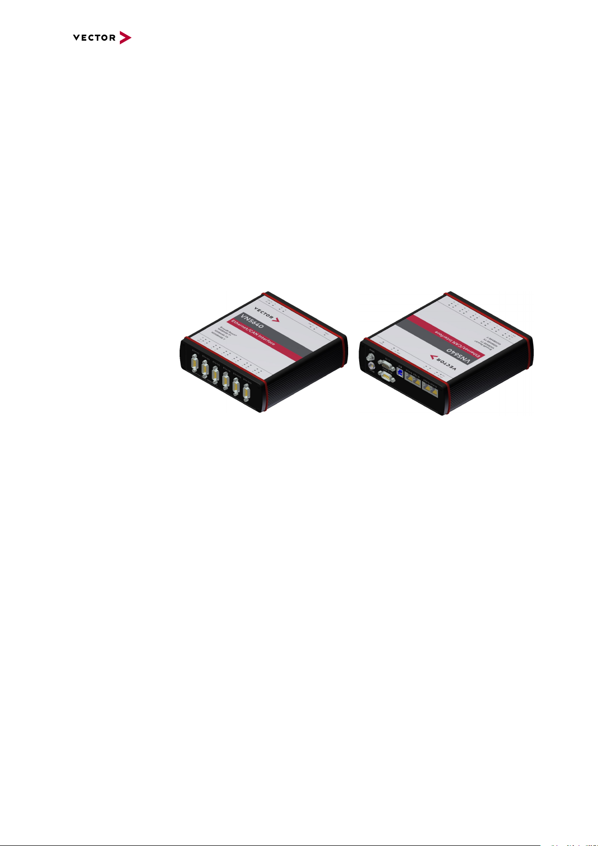
6.2 Introduction
About the VN5640 The VN5640 is a Vector network interface which supports the Ethernet physical layer
10BASE-T, 100BASE-T1 (OPEN Alliance BroadR-Reach), 100BASE-TX and
1000BASE-T. 100BASE-T1 is a physical layer especially used in automotive electronics.In addition, the alternative Interface Option 1000BASE-T1 supports
1000BASE-T1.
Figure 25: VN5640 Ethernet/CAN Interface
The VN5640 enables the transparent monitoring and logging of Ethernet data streams
and CAN events with minimal latency times and high resolution time stamps.With
this, the VN5640 enables a variety of applications such as simple bus analyses, complex remaining bus simulations as well as diagnostic and calibration (e.g. with CANalyzer.Ethernet/CANoe.Ethernet).
Highlights Features of the VN5640:
► Support of 12 independent Ethernet ports
► Support of 100BASE-T1 (OPEN Alliance BroadR-Reach)
► Support of standard Ethernet (10BASE-T/100BASE-TX/1000BASE-T)
► Support of 1000BASE-T1 (Interface Option 1000BASE-T1 only)
► Support of two independent CAN/CAN FD channels,
available as 1x D-SUB9
► Support of an IO interface for setting or sampling of analog/digital values
► Host connection via USB 3.0 or Ethernet (1000BASE-T)
► High resolution time stamps for Ethernet frames
► High resolution time stamps for CAN/CAN FD frames
► Software, hardware and IEEE 1588 time synchronization
of multiple Vector network interfaces
► Internal three-way-routing in/monitor/out
► Hardware filtering of Ethernet and CAN data
► Integrated Layer 2 switch for optimized remaining bus simulation
with several ports
VN5000 Manual Version 2.5 58
Page 59

► Hardware load generators for low jitter and full bandwidth
► Stand-alone mode capability ensures uninterrupted operation
► Robustness, power supply and temperature ranges
suitable for automotive and industrial applications
► Open interface for third-party tools
with the XL Driver Library (CAN and Ethernet)
6 VN5640
VN5000 Manual Version 2.5 59
Page 60

6.3 Main Connectors
3
1
2
1
2
Device connectors
Figure 26: Connectors on the USBside
► Sync (Binder)
The VN5640 has one sync connector (Binder type 711) which can be used for time
synchronization of different Vector devices (see section Time Synchronization on
page 135).
Pin Assignment
1 Not connected
2 Synchronization line
3 Ground
6 VN5640
► Power (ODU)
For power supply, the VN5640 has a two-pin ODU connector (MINI-SNAP size 1,
type GG1L0C-P02RP00-0000). Attach the enclosed power cable to power up the
unit (matching ODU connector type S11L0C-P02NPL0-6200).
Pin Assignment
1 Power supply (8V ... 50V)
2 Ground
Note
The VN5640 requires at least 5 V to power up. For continuous operation, use
8V or higher (typ. 12 V DC, max. 50 V). Temporary voltage drops (< 1 min)
down to 5V are allowed.
VN5000 Manual Version 2.5 60
Page 61

5
4
3
2
1
6
7
8
9
Digital Input 1
Not connected
Digital Output
Digital GND
Analog GND
Digital Input 0
Digital In/Out 1
Digital In/Out 0
Analog Input
Internal
Digital Input/Ouput
Isolation
455R
Ri
50R
50R
Vcc
GND_ISO
Passive
Network
From Processor
To Processor
GND_ISO
10k
To Processor
Digital GND
Vcc
Digital GND Digital GND
Digital Input 0/1
Isolation
20k
Vref
200k
OUT
IN-
IN+
33 V
370 pF
From Processor
Digital Output
Digital GND
Isolation
33 V
370 pF
interconnection of
digital in/out 0/1
6 VN5640
► IO 19 (D-SUB)
The VN5640 has a D-SUB9 connector (CH19) for dedicated digital input/output
tasks. The pin assignment is as follows:
Pin Assignment
1 Analog input
2 Digital input/output 0
3 Digital input/output 1
4 Digital input 0
5 Digital input 1
6 Analog GND
7 Not connected
8 Digital output
9 Digital GND
Figure 27: Digital input /output
Internal
interconnection of
digital input 0/1
Figure 28: Digital input 0/1
Internal
interconnection of
digital output
VN5000 Manual Version 2.5 61
Figure 29: Digital output
Page 62
Internal
To Processor
Analog GND
Vcc
Analog Input
100k
1M
33 V
370 pF
Analog GND
22 pF
ADC
15k
10k
Analog GND
OUT
IN+
IN-
Isolation
INOUT
interconnection of
analog input
6 VN5640
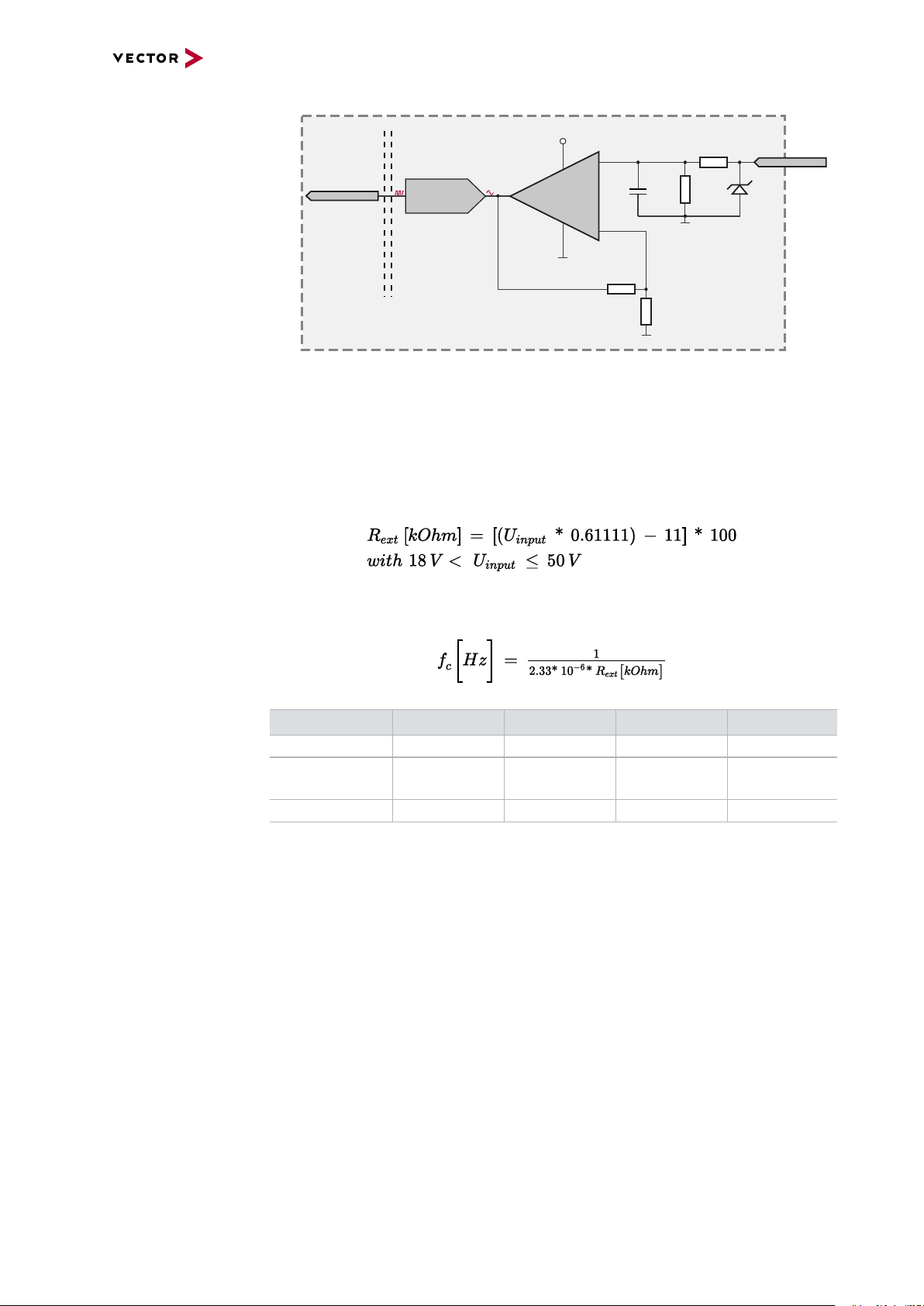
Figure 30: Analog input
Extended measuring
range of the
In normal operation, voltages up to 18 V can be applied and measured at the analog
input. The cutoff frequency fc(-3 dB) for AC voltages is approx. 7.2 kHz.
analog input
For measurements above 18 V (max. 50 V), an external series resistor has to be
applied to the analog input. The series resistor R
voltage U
to be measured and can be calculated as follows:
input
depends on the maximum input
ext
The cutoff frequency for AC voltages is also affected by the external series resistor:
Examples 24 V 32 V 36 V 48 V
R
ext
R
(E96) 374 kΩ
ext
367 kΩ 856 kΩ 1100 kΩ 1833 kΩ
(24.12 V)
866 kΩ
(32.17 V)
1100 kΩ
(36.00 V)
1870 kΩ
(48.60 V)
fc(-3 dB) 1148Hz 496Hz 390Hz 230Hz
VN5000 Manual Version 2.5 62
Page 63
6 VN5640
5
4
3
2
1
6
789
Not connected
Reserved
1051cap CAN High
1051cap GND
1051cap CAN Low
1051cap CAN Low
1051cap GND
1051cap CAN High
Not connected
CH17
CH18
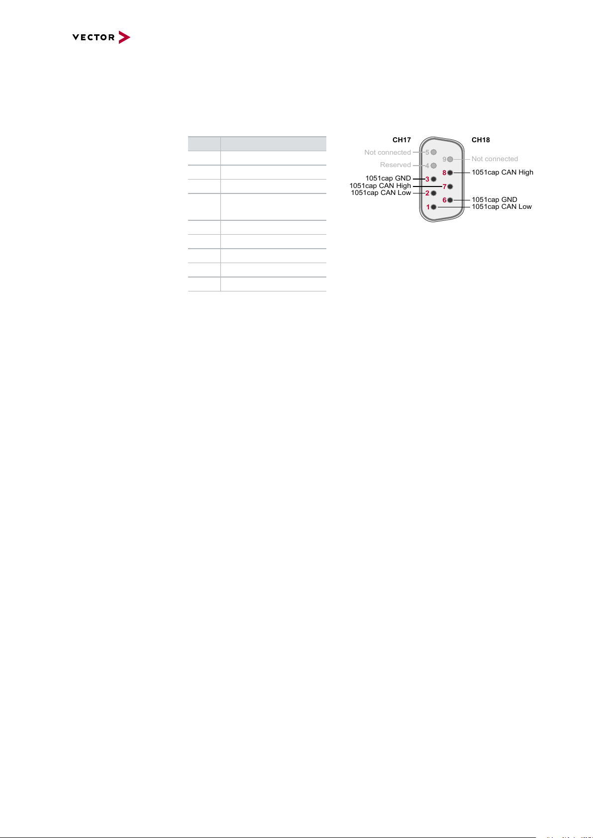
► CAN CH17/18 (D-SUB)
D-SUB connector with two CAN channels. Use the CANcable 2Y to access both
channels on separate D-SUB9 connectors (see accessories manual, part number
05075).
Pin Assignment
1 CH18 CAN Low
2 CH17 CAN Low
3 CH17 GND
4 Reserved.
Please do not use.
5 Not connected
6 CH18 GND
7 CH17 CAN High
8 CH18 CAN High
9 Not connected
► USB
Connect your PC and the VN5640 over USB to install and to use the device with
measurement applications (CANoe, CANalyzer). Use the USB 3.0 compliant
cable found in the delivery (USB extension cables may generate faults between
the PC and the device). Connect the device directly to a USB port at your PC or
use a USB hub with its own power supply (self-powered).
► Ethernet 13...16 (Ethernet)
Standard Ethernet connector for 10BASE-T, 100BASE-TX and 1000BASE-T.
VN5000 Manual Version 2.5 63
Page 64
6.4 LEDs
Top LEDs
6 VN5640
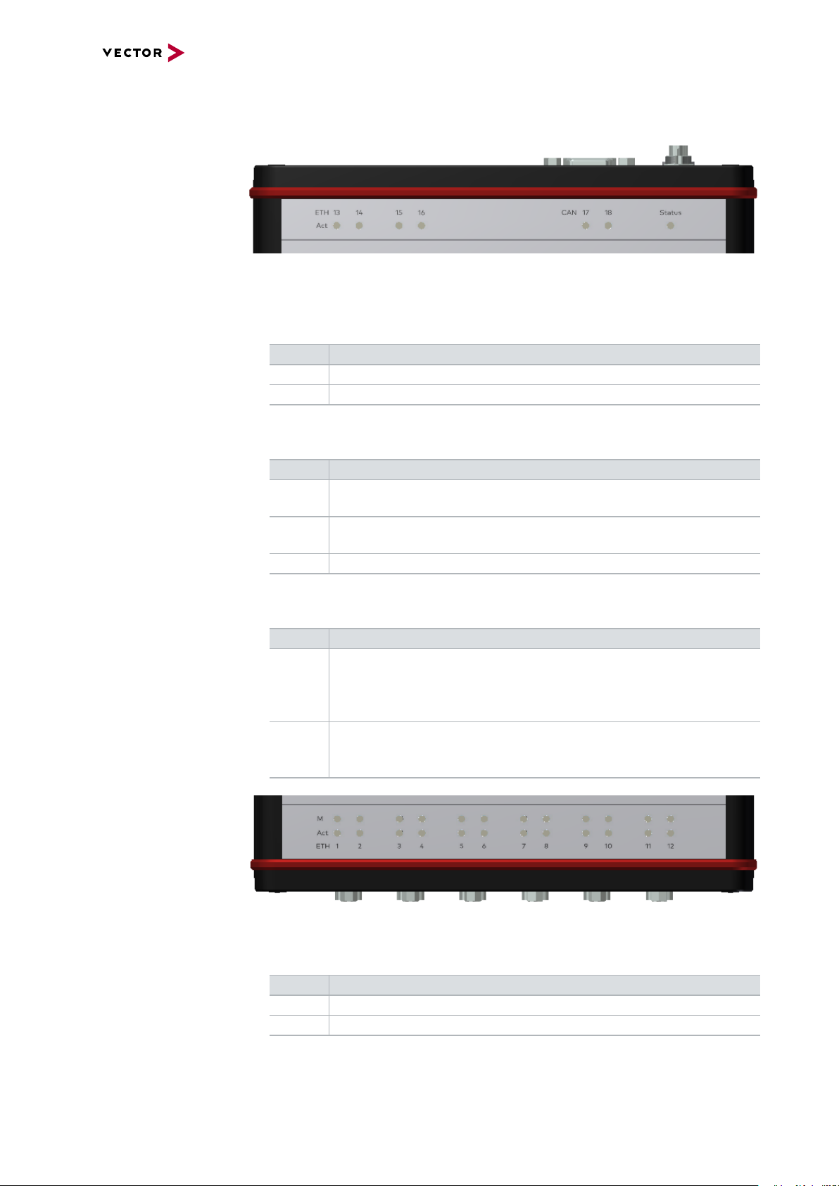
Figure 31: Top LEDs on VN5640
► Act (Ethernet Port 13...16)
LED illuminates if there is an Ethernet link or blinks if there is Ethernet activity at
the according port.
Color Description
Green 1000MBit.
Orange 100MBit.
► CAN (CH17/CH18)
Multicolored channel LEDs, each indicating the bus activity for CAN.
Color Description
Green Data frames have been sent or received correctly.
The flashing frequency varies according to the message rate.
Orange Error frames have been sent or received.
The flashing frequency varies according to the message rate.
Red Bus off.
Bottom LEDs
► Status
Multicolored LED indicating the status.
Color Description
Green Blinks 4x at power up and illuminates afterwards.
Blinks quicker during an update progress. Please wait for the automatic reboot of the device (approx. 60 seconds) after the update has
been finished.
Red An error has occurred. Please disconnect the power supply as well as
the USB cable. Re-connect the power supply and the USB cable and
try again.
Figure 32: Bottom LEDs on VN5640
► M (Ethernet Port 1...12)
Illuminates if the according port is configured as master.
Color Description
Green PHY is configured as master.
Off PHY is configured as slave.
VN5000 Manual Version 2.5 64
Page 65

6 VN5640
► Act (Ethernet Port 1...12)
LED illuminates if there is an Ethernet link or blinks if there is Ethernet activity at
the according port.
Color Description
Green 1000MBit.
Orange 100MBit.
Note
During a firmware update process, the LEDs of port 1...12 turns into a progress
bar.
VN5000 Manual Version 2.5 65
Page 66
6.5 Interface Option 100BASE-T1
5
4
3
2
1
6
7
8
9
N
P
Not connected
Not connected
Not connected
Not connected
P
N
Not connected
Port 1 Port 2
6.5.1 Connectors
Device connectors
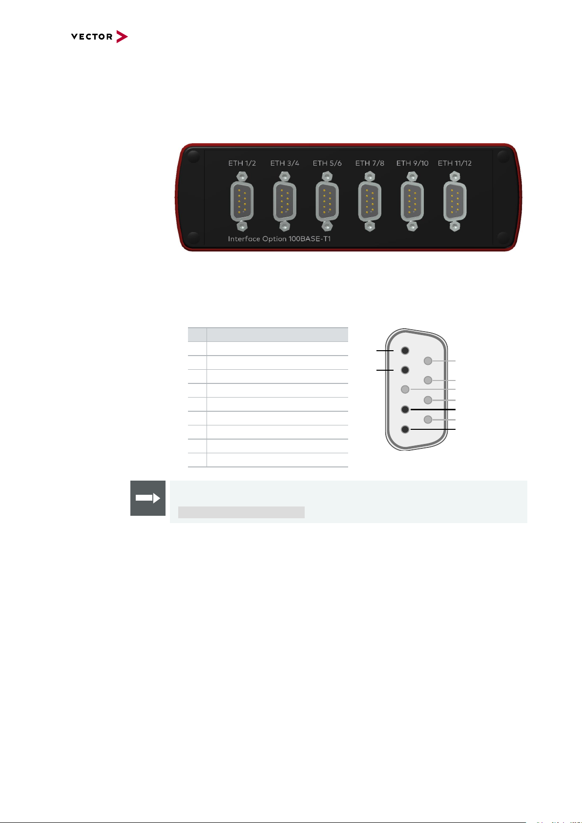
Figure 33: Ethernet CH1...CH12
► Ethernet Port 1...12 (D-SUB9)
D-SUB9 connector for 100BASE-T1. Use the BRcable 2Y to access both ports
on separate D-SUB9 connectors (see accessories manual, part number 05103).
6 VN5640
Pin Assignment
1 CH2 P
2 CH2 N
3 Not connected
4 CH1 P
5 CH1 N
6 Not connected
7 Not connected
8 Not connected
9 Not connected
Reference
The Ethernet configuration can be done in Vector Hardware Config (see section
Ethernet Device Configuration on page 116).
VN5000 Manual Version 2.5 66
Page 67

6.5.2 Technical Data
6.5.2.1 Overview
Ethernet ports 12x NXP TJA1101
CAN/CAN FD channels 2x NXP TJA1051
Analog input 10 bit
Digital input Range 0 V...32 V
Digital output Open Drain
Digital input/output Push/Pull mode (e.g. DoIP Activation Line)
Time stamps Resolution: 15.625 ns
PC interface USB 3.0 or Ethernet (1000BASE-T)
Input voltage Power-up: min. 5V
Power consumption Max. 15 W
Temperature range
(ambient temp. of the device)
Relative humidity
of ambient air
Dimensions (LxWxH) 186 mm x 172 mm x 55 mm
Weight 1300g
Operating system requirements Windows 7 SP1 (32 bit / 64 bit)
6 VN5640
(IEEE 100BASE-T1)
4x Atheros AR8031
(IEEE 100BASE-TX/1000BASE-T)
Input 0 V...18 V (Ri = 1.1 MΩ)
Voltage tolerance up to 30 V
Details on the extended measuring range
see on page 62.
Schmitt trigger high 2.8 V, low 2.3 V
Input frequencies up to 1 kHz
External supply up to 32 V
Output frequency up to 1 kHz
Current max. 500 mA
Short circuit / over voltage protected
or only Push-Mode (e.g. Wake-up Triggers)
Output high (no load): 13 V
Output high (load 346Ω): 5.3 V
Output low: 0V
Input range: 0V…16V
Input Schmitt trigger high: 3.4V
Input Schmitt trigger low: 2.5V
Rout: approx. 500Ω
Accuracy (in device): 1 µs
Accuracy software sync: typ. 50 µs
Accuracy hardware sync: typ. 1 µs
Continuous operation: 8 V … 50 V (typ. 12V)
Temporary voltage drop down (< 1 min) to 5 V
Operation: -40 °C ... +60 °C
Storage: -40 °C ... +85 °C
15 %...95 %, non-condensing
Windows 8.1 (32 bit / 64 bit)
Windows 10 (64 bit)
VN5000 Manual Version 2.5 67
Page 68

6.5.2.2 Electrical Isolation
Case
12345
6789
Ethernet
1...12
Ethernet
13...16
Shield
Supply/Data
Connected
Electrical
Isolation
USB
Shield
12345
6789
CAN 17/18
Shield
CH17
CH18
GND
ISO_CH18
GND
ISO_CH17
Sync
3 1
2
Shield
GND
ISO_SYNC
12345
6789
IO 19
GND
ISO_DIGITAL
GND
ISO_ANALOG
Logic
GND
Shield
Shield
Electrical isolation
of the connectors
6 VN5640
Note
Please note that shielded cables and the USBconnector on the device share the
same potential (see picture above) while the host shield is connected to GND. This
can lead to ground loops and to damages on the host because of currents when
using a 12 V notebook power supply without electrical isolation. Please always use
an electrical isolated power supply for the host.
VN5000 Manual Version 2.5 68
Page 69

Electrical isolation
7
2
3
7
8
2
1
3
6
D-SUB9
CAN High
Power
Ground
Ground
CAN Low
CAN GND
TJA1051
Signal isolator
DC/DC
CAN High
Power
Ground
Ground
CHA
CHB
CAN Low
CAN GND
TJA1051
Signal isolator
DC/DC
4
5
1
2
D-SUB9
Ethernet P
Power
Power
GND
GND
MII A
MII B
Ethernet N
GND
Shield
TJA1101
TJA1101
Ethernet P
CHA
CHB
Ethernet N
of CAN in detail
Electrical isolation
of Ethernet in detail
6 VN5640
VN5000 Manual Version 2.5 69
Page 70

6.5.3 Network Features
6 VN5640
Ports/channels
Device sync Hardware synchronization X
Infrastructure PC uplink USB3.0 / 1000BASE-T
Application area Measurement / analysis X
Port interconnection Layer 2 Switch X
1000BASE-T1 100BASE-T1 12
10/100/1000BASE-T(X) 4
1, 2.5, 5, 10G BASE-T CAN-FD 2
DoIP Activation / Wake-up Line X
Multiple digital / analog IO X
Software synchronization X
IEEE1588 (PTP) X
Power supply Ext. power supply
Simulation X
Test X
TAP X
Media conversion 4
Link transparency X
OPEN Alliance TC10 (Wake/Sleep) X
Physical bypass relays Ports interconnectable at the same time 12
Measure Mirroring port X
Uplink frame filter 16 rules
Error frame reporting X
VLAN tagging / untagging / routing X
Virtual ports 32
Test Onboard packet generator X
Error frame generation X
OPEN Alliance TC10 (Wake/Sleep) X
VN5000 Manual Version 2.5 70
Page 71

6.6 Interface Option 1000BASE-T1
12345
109876
5
4
3
2
1
6
7
8
9
N
P
Not connected
Not connected
Not connected
Not connected
P
N
Not connected
Port 1 Port 2
6.6.1 Connectors
Device connectors
Figure 34: Ethernet CH1...CH12
► Ethernet Port 1...6 (ix Industrial®)
ix Industrial® connectors for 100BASE-T1/1000BASE-T1 (e.g. Harting ix Industrial® type 10A-1). Each connector has two Ethernet ports (A and B). Use cables
of the Vector AEcable 2Y family to access both ports on separate connectors (different plug systems available).
6 VN5640
Pin Assignment
1 CH2 P
2 CH2 N
3 Not connected
4 Not connected
5 Not connected
6 CH1 P
7 CH1 N
8 Not connected
9 Not connected
10 Not connected
► Ethernet Port 7...12 (D-SUB9)
D-SUB9 connector for 100BASE-T1. Use the BRcable 2Y to access both ports
on separate D-SUB9 connectors (see accessories manual, part number 05103).
Pin Assignment
1 CH2 P
2 CH2 N
3 Not connected
4 CH1 P
5 CH1 N
6 Not connected
7 Not connected
8 Not connected
9 Not connected
VN5000 Manual Version 2.5 71
Page 72

6 VN5640
Reference
The Ethernet configuration can be done in Vector Hardware Config (see section
Ethernet Device Configuration on page 116).
VN5000 Manual Version 2.5 72
Page 73

6.6.2 Technical Data
6.6.2.1 Overview
Ethernet ports 6x Marvell 88Q2112 Rev.A2
CAN/CAN FD channels 2x NXP TJA1051
Analog input 10 bit
Digital input Range 0 V...32 V
Digital output Open Drain
Digital input/output Push/Pull mode (e.g. DoIP Activation Line)
Time stamps Resolution: 15.625 ns
PC interface USB 3.0 or Ethernet (1000BASE-T)
Input voltage Power-up: min. 5V
Power consumption Max. 15 W
Temperature range
(ambient temp. of the device)
Relative humidity
of ambient air
Dimensions (LxWxH) 186 mm x 172 mm x 55 mm
Weight 1300g
Operating system requirements Windows 7 SP1 (32 bit / 64 bit)
6 VN5640
(IEEE 100BASE-T1/1000BASE-T1)
6x Broadcom BCM89811
(IEEE 100BASE-T1)
4x Atheros AR8031
(IEEE 100BASE-TX/1000BASE-T)
Input 0 V...18 V (Ri = 1.1 MΩ)
Voltage tolerance up to 30 V
Details on the extended measuring range
see on page 62.
Schmitt trigger high 2.8 V, low 2.3 V
Input frequencies up to 1 kHz
External supply up to 32 V
Output frequency up to 1 kHz
Current max. 500 mA
Short circuit / over voltage protected
or only Push-Mode (e.g. Wake-up Triggers)
Output high (no load): 13 V
Output high (load 346Ω): 5.3 V
Output low: 0V
Input range: 0V…16V
Input Schmitt trigger high: 3.4V
Input Schmitt trigger low: 2.5V
Rout: approx. 500Ω
Accuracy (in device): 1 µs
Accuracy software sync: typ. 50 µs
Accuracy hardware sync: typ. 1 µs
Accuracy PTP sync (IEEE1588): typ. 1µs
Continuous operation: 8 V … 50 V (typ. 12V)
Temporary voltage drop down (< 1 min) to 5 V
Operation: -40 °C ... +60 °C
Storage: -40 °C ... +85 °C
15 %...95 %, non-condensing
Windows 8.1 (32 bit / 64 bit)
Windows 10 (64 bit)
VN5000 Manual Version 2.5 73
Page 74
6.6.2.2 Electrical Isolation
Case
Ethernet
7...12
Ethernet
13...16
Shield
Supply/Data
Connected
Electrical
Isolation
USB
Shield
1 2 3 45
6 7 8 9
CAN 17/18
Shield
CH17
CH18
GND
ISO_CH18
GND
ISO_CH17
Sync
3 1
2
Shield
GND
ISO_SYNC
3
IO 19
GND
ISO_DIGITAL
GND
ISO_ANA
LOG
Logic
GND
Shield
Shield
5 4 2 1
89 7 6
35 4 2 1
89 7 6
Ethernet
Shield
12345
109876
1...6
Electrical isolation
of the connectors
6 VN5640
Note
Please note that shielded cables and the USBconnector on the device share the
same potential (see picture above) while the host shield is connected to GND. This
can lead to ground loops and to damages on the host because of currents when
using a 12 V notebook power supply without electrical isolation. Please always use
an electrical isolated power supply for the host.
Note
The usage of an AEcable 2Y is recommended because it separates the interface's
shield potential from the ECU shield potential. This ensures that all compensating
currents over the shields are avoided. A capacitive coupling of the shields is implemented in the AEcable 2Y.
VN5000 Manual Version 2.5 74
Page 75
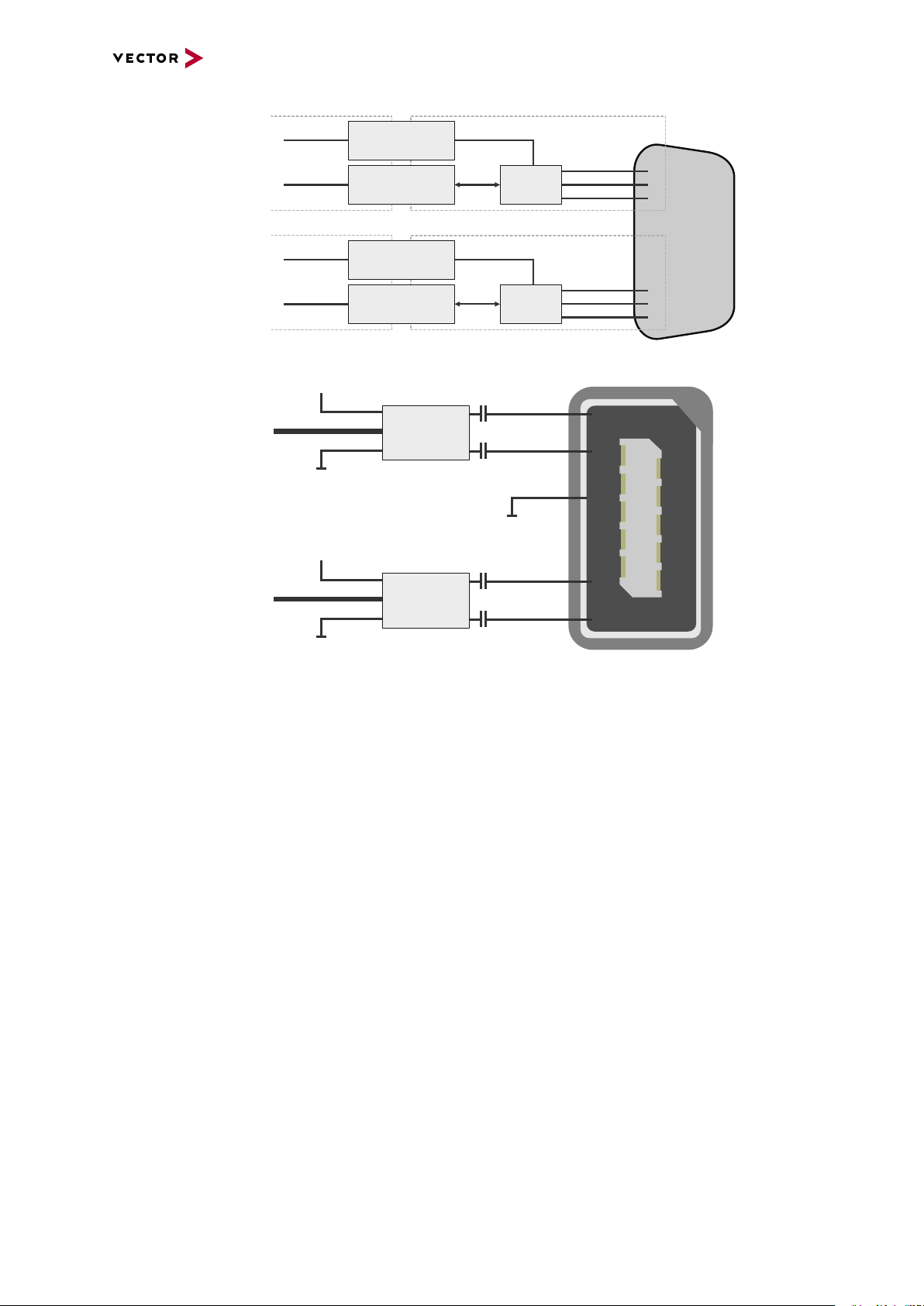
Electrical isolation
7
2
3
7
8
2
1
3
6
D-SUB9
CAN High
Power
Ground
Ground
CAN Low
CAN GND
TJA1051
Signal isolator
DC/DC
CAN High
Power
Ground
Ground
CHA
CHB
CAN Low
CAN GND
TJA1051
Signal isolator
DC/DC
5
6
1
2
iX
Ethernet P
Power
Power
GND
GND
MII A
MII B
Ethernet N
FE
Shield
88Q2112
88Q2112
Ethernet P
CHA
CHB
Ethernet N
of CAN in detail
Electrical isolation
of Ethernet in detail
6 VN5640
VN5000 Manual Version 2.5 75
Page 76

6.6.2.3 Network Features
6 VN5640
Ports/channels
Device sync Hardware synchronization X
Infrastructure PC uplink USB3.0 / 1000BASE-T
Application area Measurement / analysis X
Port interconnection Layer 2 Switch X
1000BASE-T1 6
100BASE-T1 12
10/100/1000BASE-T(X) 4
1, 2.5, 5, 10G BASE-T CAN-FD 2
DoIP Activation / Wake-up Line X
Multiple digital / analog IO X
Software synchronization X
IEEE1588 (PTP) X
Power supply Ext. power supply
Simulation X
Test X
TAP X
Media conversion 4
Link transparency X
OPEN Alliance TC10 (Wake/Sleep) Physical bypass relays Ports interconnectable at the same time 12
Measure Mirroring port X
Uplink frame filter 16 rules
Error frame reporting X
VLAN tagging / untagging / routing X
Virtual ports 32
Test Onboard packet generator X
Error frame generation X
OPEN Alliance TC10 (Wake/Sleep) -
VN5000 Manual Version 2.5 76
Page 77

6.7 Accessories
Note
Detailed information on the listed accessories can be found in the separate
accessories manual on our website.
6 VN5640
Cables and
connectors
► AEcable 2Y
► BRcable 2Y
► VNcable D-SUB9 HSD Z
► Ethernetcables
► CANcable1
► CANcableA
► CANcable TnT
► CANcable Y
► CANcable 2Y
► CANterm 120
► CANcable Set Pro
► SYNCcableXL
► SYNCcable50
► Multi SYNCbox external
► Multi SYNCbox internal
► Multi SYNCbox active
► Connection Cable Binder Type 711
► USB Cable 3.0
Power supply ► Vector Power Supply ODU MINI-SNAP
► Vehicle Input <> ODU MINI-SNAP
► ODU Connector / Bunch Plugs
Miscellaneous ► Fix Kit Large Device
VN5000 Manual Version 2.5 77
Page 78

7 VN5240
7 VN5240
In this chapter you find the following information:
7.1 Scope of Delivery 79
7.2 Introduction 79
7.3 Connectors 81
7.3.1 Front Side 81
7.3.2 Back Side 82
7.4 LEDs 83
7.5 Technical Data 84
7.5.1 Overview 84
7.5.2 Temperature Shutdown 84
7.5.3 Electrical Isolation 86
7.5.4 Network Features 88
7.6 Accessories 90
7.6.1 VSH Cable Guard 216 91
VN5000 Manual Version 2.5 78
Page 79
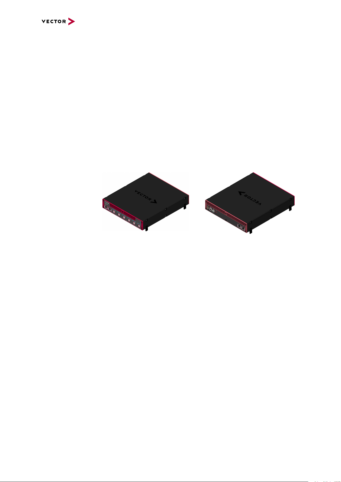
7 VN5240
7.1 Scope of Delivery
Contents The delivery includes:
► 1x VN5240 Ethernet Measurement Interface
► 1x Bunch Plugs (part number 05069)
► 1x Ethernet cable CAT6A (2m)
7.2 Introduction
About the VN5240 The VN5240 is an interface that has been specially designed for monitoring and ana-
lysis of Ethernet networks. For recording Ethernet data in the vehicle, the VN5240 is
ideal in combination with the VP6400 smart logging platform. The
interface is connected to the computer via Ethernet (10GBASE-T). The tapped datastreams can also be accessed very flexible via up to three mirroring ports.
Figure 35: VN5240 Ethernet Interface
Highlights Features of the VN5240:
► 12x user port 100BASE-T1/ 1000BASE-T1
► 2x infrastructure port 10/100/1000BASE-T(X)
► 2x infrastructure port 1G/2.5G/5G/10GBASE-T
usable:
- as uplink to host PC
- as an alternative user port (e.g. to analyze traffic of a 100BASE-
TX/10000BASE-T link)
► Host connection Ethernet (10GBASE-T)
► Onboard Ethernet TAPs to link between two Ethernet ports
► New hardware configuration concept for flexible configuration
► Usable without host-connection to interconnect ECUs
- Self-configuration after power-up
► Hardware filtering of Ethernet packets on protocol base
► Hardware synchronization to other Vector interfaces via
- IEEE 1588 (PTP)
- software synchronization (typ. 50µs accuracy)
- hardware synchronization (1µs accuracy)
► Multi-application support (different tools can share an Ethernet port at the same
time)
► Support of 3rd party tools with free XL Driver Library
► Provides high precision time stamped Ethernet frames (< 20 ns precision)
► Device is designed for in-vehicle applications:
- Robust housing with various mounting possibilities
VN5000 Manual Version 2.5 79
Page 80

7 VN5240
- Form-factor fits perfect two times in a standard 19-inch rack system
- Extended power supply range (8V…32V)
- Extended temperature-range (-40°C...+65°C)
- Low-power soft off mode (only 2mA power consumption)
- Onboard/configurable high frequency Ethernet bypass relays ensure a closed
TAP connection between two ECUs while the VN5240 is not powered
VN5000 Manual Version 2.5 80
Page 81
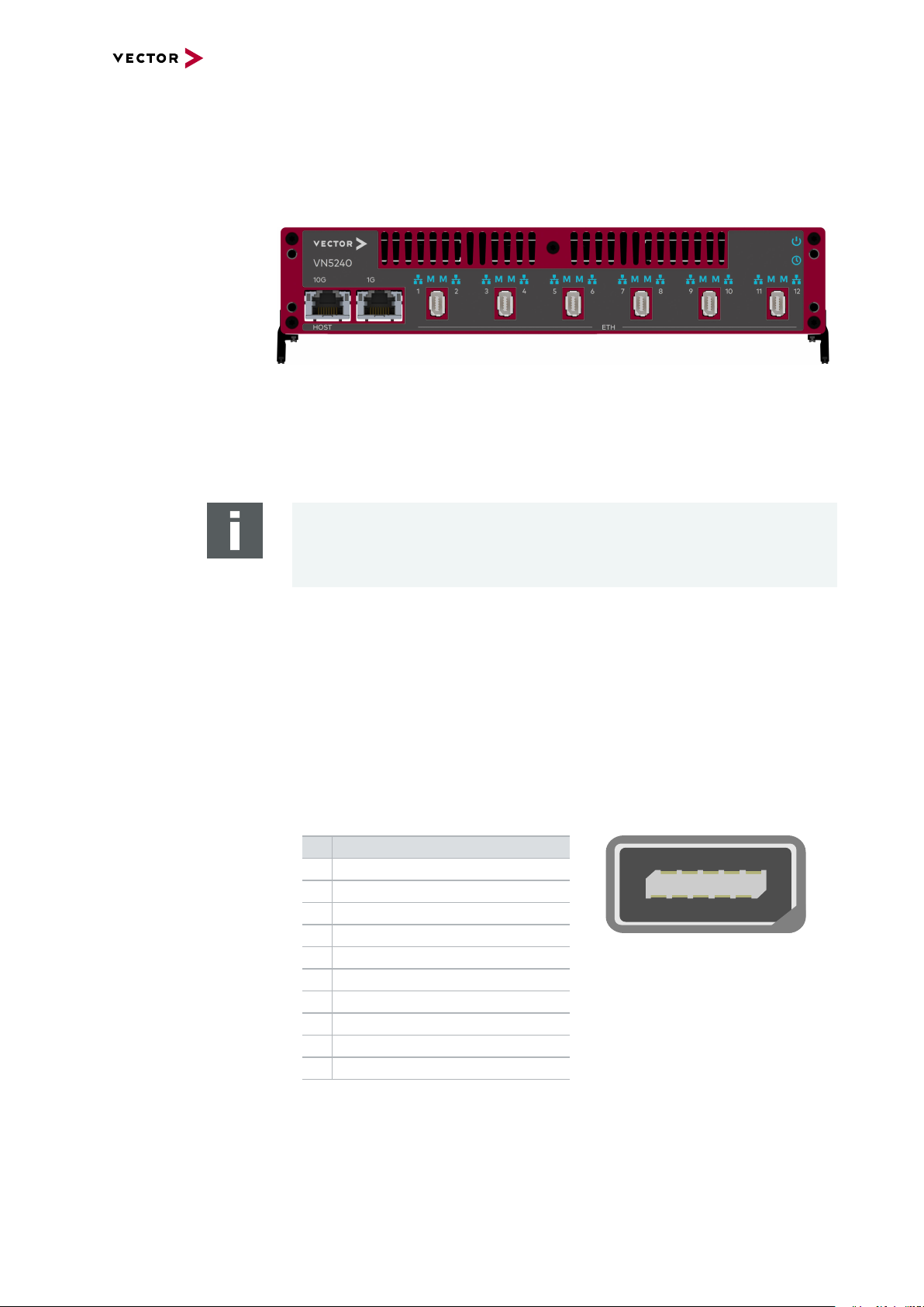
7.3 Connectors
12345
109876
7.3.1 Front Side
Device connectors
Figure 36: Connectors on the Ethernet side
► Host 10G (RJ45)
Connect your PC and the VN5240 via RJ45 to use the device with measurement
applications (e. g. CANoe, CANalyzer) in a network setup. Alternatively, you also
can configure 1G.
7 VN5240
Note
10Gbps Ethernet connections exhibit an increased sensitivity to EMI.
Data integrity is guaranteed by use of protocols which may reduce data throughput.
► 1G (RJ45)
Infrastructure port with different possible configurations:
- mirror port
- alternative analysis port
► Ethernet 1...12 (ix Industrial)
ix Industrial connectors for 100BASE-T1/1000BASE-T1 (e.g. Harting ix Industrial
type 10A-1). Each connector has two Ethernet ports (A and B). Use cables of the
Vector AEcable 2Y family to access both ports on separate connectors (different
plug systems available)
Pin Assignment
1 CH2 P
2 CH2 N
3 Not connected
4 Not connected
5 Not connected
6 CH1 P
7 CH1 N
8 Not connected
9 Not connected
10 Not connected
VN5000 Manual Version 2.5 81
Page 82

7.3.2 Back Side
1
2
3 1
2
Device connectors
7 VN5240
Figure 37: Connectors on the USB side
► Functional Earth (FE)
Optional connection of housing ground to system ground.
► Power (ODU)
For power supply, the VN5420 has a two-pin ODU connector (MINI-SNAP size 1,
type GF1L0C-P02RP00-0000). Attach the enclosed power cable to power up the
unit (matching ODU connector type S11L0C-P02NPL0-6200).
Pin Assignment
1 Power supply (8V ... 32V)
2 Ground
► Sync (Binder)
The VN5240 has a sync connector (Binder type 711) which can be used for time
synchronization of different Vector devices (see section Time Synchronization on
page 135).
Pin Assignment
1 Terminal 15
2 Synchronization line
3 Ground Sync
► Kensington Lock
Mounting of Nano Kensington (NanoSaver).
► Reset
If the device configuration is corrupted, start it with pushed reset button.
► 1G/10G (RJ45 connectors)
Infrastructure port with different possible configurations:
- mirror port
- alternative analysis port
VN5000 Manual Version 2.5 82
Page 83

7.4 LEDs
LEDs
7 VN5240
Figure 38: LEDs on VN5240
► Power
LED illuminates if the device is supplied with power.
► Sync
LED illuminates if the device is synchronized.
► RJ45
LEDs illuminate if there is an Ethernet link or blink if there is Ethernet activity.
Color (Left) Color (Right) Description
Orange - 100M
Green - 1G
- Orange 2.5G
- Green 5G
Orange Orange 10G
► (Ethernet Port 1...12)
LED illuminates if there is an Ethernet link or blinks if there is Ethernet activity at
the according port.
Color Description
Green 1000MBit.
Orange 100MBit.
►M(Ethernet Port 1...12)
Illuminates if the according port is configured as master.
State Description
On PHY is configured as master.
Off PHY is configured as slave.
VN5000 Manual Version 2.5 83
Page 84

7.5 Technical Data
7.5.1 Overview
Ethernet ports 12x Broadcom BCM89883
Time stamps Resolution: 15.625 ns
PC interface Ethernet (1/2.5/5/10GBASE-T)
Power supply External: 8V...32V (typ. 12VDC)
Power consumption Typ. 2A @ 12V
Temperature range Operation: -40 °C ... +65 °C
Relative humidity
of ambient air
Dimensions (LxWxH) Approx. 216mm x 258mm x 54mm
Weight Approx. 2.5kg
Operating system requirements Windows 10 (64 bit)
7 VN5240
(IEEE 100BASE-T1/ 1000BASE-T1)
2x Broadcom BCM54210
(IEEE 1000BASE-T/100BASE-TX)
2x Broadcom BCM84891
(IEEE 1/2.5/5/10GBASE-T)
Accuracy (in device): 1 µs
Accuracy software sync: typ. 50 µs
Accuracy hardware sync: typ. 1 µs
Accuracy PTP sync (IEEE1588): typ. 1µs
Max. 3.1A @ 12 V (65°C)
Standby: 2 mA @ 12V
Storage: -40 °C ... +85 °C
15 %...95 %, non-condensing
7.5.2 Temperature Shutdown
Temperature
limits
The units are temperature monitored to prevent damage to the unit. The devices
switch off automatically when the upper limit temperature is exceeded. This limit
value represents the theoretical maximum of the hardware. However, it is possible to
leave this range slightly without damaging the hardware.
For this purpose the temperature shutdown can be switched off actively.
If the maximum temperature is exceeded, it is indicated by a red status LED on the
device. Vector applications also display this (e.g. in the Write window of CANoe).
You can find the settings in the Vector Hardware Config tool.
VN5000 Manual Version 2.5 84
Page 85

Figure 39: Open configuration
7 VN5240
Figure 40: Setting limit for shutdown
VN5000 Manual Version 2.5 85
Page 86
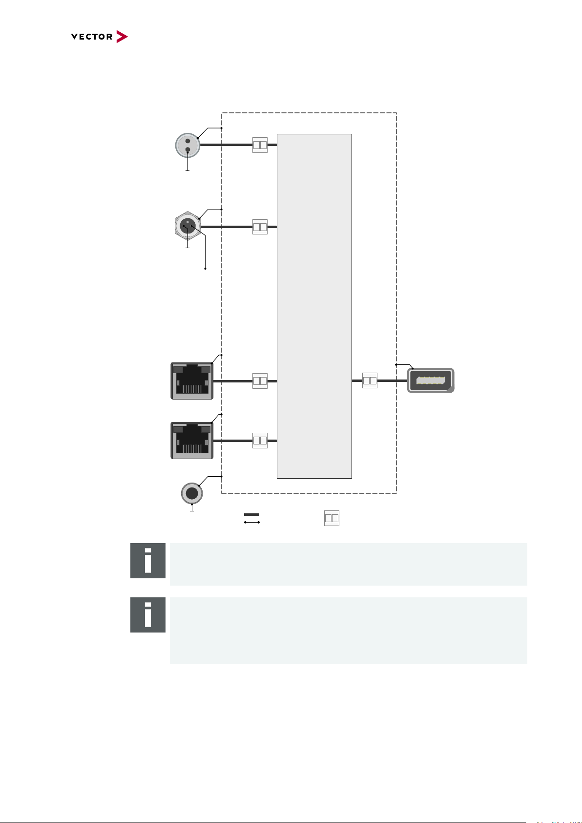
7.5.3 Electrical Isolation
Case
Supply/Data
Connected
Electrical
Isolation
Power
Sync
Shield
Shield
Shield
Shield
Shield
GND
ISO_SYNC
GND_PWR
Term_15
(related to
GND_PWR)
3 1
2
Ethernet
1G
Ethernet
10G
FE
Shield
12345
109876
Ethernet
Port 1..12
Logic
1
2
Electrical isolation
of the connectors
7 VN5240
Note
The FE plug must be connected to the chassis ground if the network interface is
used in a vehicle with shieled cables.
Note
The usage of an AEcable 2Y is recommended because it separates the interface's
shield potential from the ECU shield potential. This ensures that all compensating
currents over the shields are avoided. A capacitive coupling of the shields is implemented in the AEcable 2Y.
VN5000 Manual Version 2.5 86
Page 87

Electrical isolation
5
6
1
2
iX
Ethernet P
Power
Power
GND
GND
MII A
MII B
Ethernet N
FE
Shield
BCM89883
BCM89883
Ethernet P
CHA
CHB
Ethernet N
of Ethernet in detail
7 VN5240
VN5000 Manual Version 2.5 87
Page 88

7.5.4 Network Features
7 VN5240
Ports/channels
Device sync Hardware synchronization X
Infrastructure PC uplink 10GBASE-T
Application area Measurement / analysis X
Port interconnection Layer 2 Switch -
1000BASE-T1 / 100BASE-T1 12
10/100/1000BASE-T(X) 2
1, 2.5, 5, 10G BASE-T 2
CAN-FD DoIP Activation / Wake-up Line Multiple digital / analog IO -
Software synchronization X
IEEE1588 (PTP) X
Power supply Ext. power supply
Simulation Test -
TAP X
Media conversion 4
Link transparency X
OPEN Alliance TC10 (Wake/Sleep) Physical bypass relays X
Ports interconnectable at the same time 12
Measure Mirroring port X
Uplink frame filter 16 rules
Error frame reporting X
VLAN tagging / untagging / routing Virtual ports -
Test Onboard packet generator -
Error frame generation OPEN Alliance TC10 (Wake/Sleep) -
VN5000 Manual Version 2.5 88
Page 89

7.5.4.1 Physical Bypass Relay
VN5000
PHY1 PHY2
ECU1 ECU2
VN5000
PHY1 PHY2
ECU1 ECU2
General information If a Vector Ethernet Network Interface is connected as TAP between two
100/1000BASE-T1 nodes, the communication of the two terminals is permanently
interrupted when the interface is switched off or fails. By activating the physical
bypass on the Vector Ethernet Network Interface, this communication can still be
enabled. This physical bypass can be activated and deactivated via software, resulting in the following options or operation modes:
Operation Mode After Booting Before Shutdown
2-channel mode bypass inactive bypass inactive
physical bypass mode bypass inactive bypass active
passive mode bypass active bypass active
The terms bypass active or bypass inactive are explained in the following figures:
7 VN5240
Figure 41: Bypass inactive, Vector Ethernet Network Interface tunnels ECUs
Figure 42: Bypass active, Vector Ether net Network Interface is switched off
Note
If the physical bypass is active, the interface cannot read the data.
Note
When switching the relay, the link is briefly interrupted for 200ms.
VN5000 Manual Version 2.5 89
Page 90

7.6 Accessories
Note
Detailed information on the listed accessories can be found in the separate
accessories manual on our website.
7 VN5240
Cables and
connectors
Power supply ► Vector Power Supply ODU MINI-SNAP
Miscellaneous ► VSH Cable Guard 216
► AEcable 2Y
► Ethernetcables
► SYNCcableXL
► SYNCcable50
► Multi SYNCbox external
► Multi SYNCbox internal
► Multi SYNCbox active
► Connection Cable Binder Type 711
► ODU Connector / Bunch Plugs
► VSH Cable Guard 216 Clip
► VSH Connecting Kit 19"
► VSH Connecting Kit Horizontal
► VSH Connecting Kit Vertical
► VSH Equipment Foot Kit
► VSH Mounting Flange
VN5000 Manual Version 2.5 90
Page 91
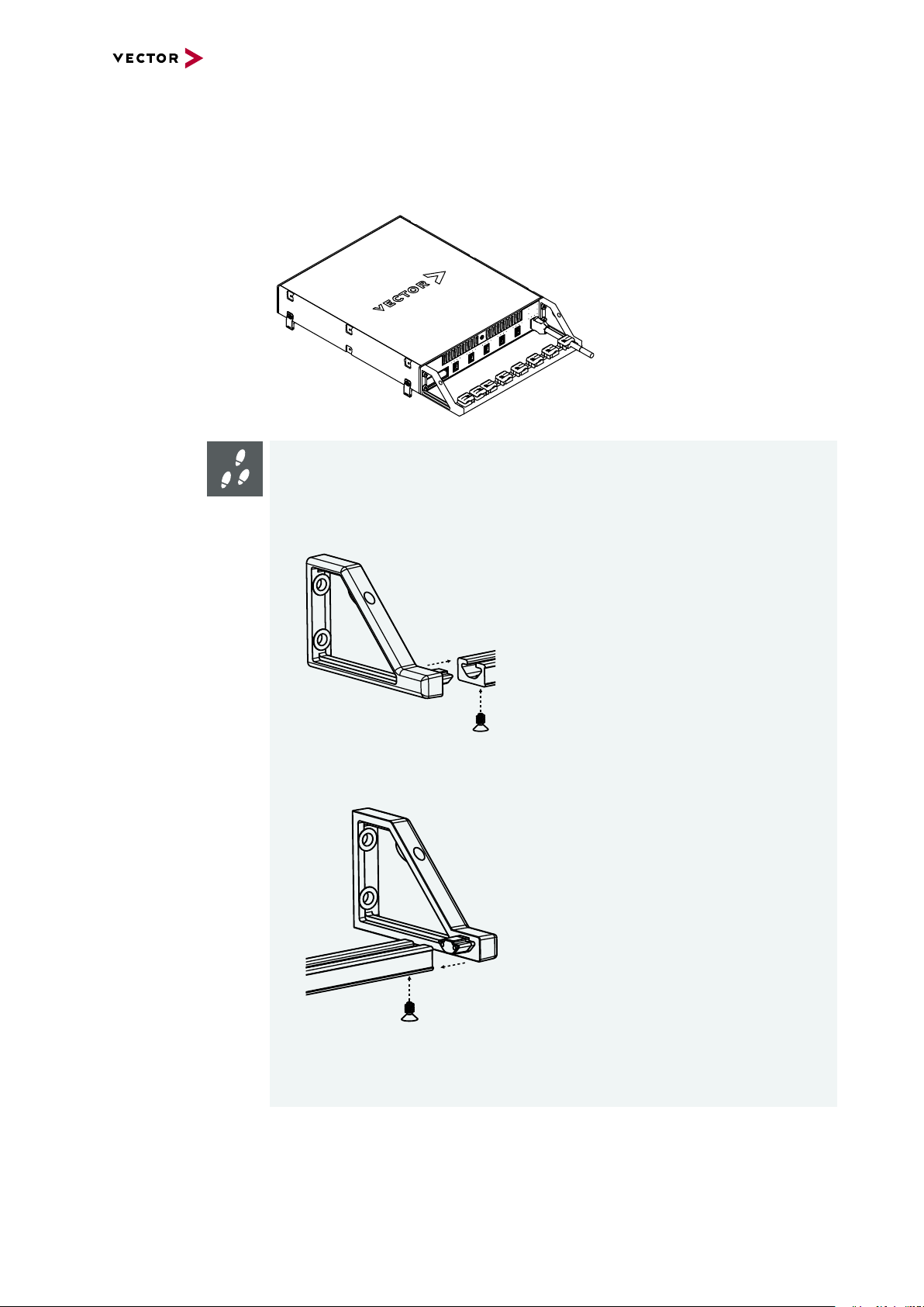
7.6.1 VSH Cable Guard 216
To protect the connectors of the VN device against mechanical damages, the VSH
Cable Guard 216 (part number 05149) can be used. The VSH Cable Guard 216 is part
of the standard delivery and available as accessory, too.
Step by Step Procedure
The following steps describe the mounting of the VSH Cable Guard 216:
7 VN5240
1. Insert the left frame into the cable rail and tighten the screw (Torx8) with a
torque of 1.4Nm.
2. Repeat the steps above with the right frame.
3. Carefully remove the decorative caps and the four screws on the front of the
VN device.
VN5000 Manual Version 2.5 91
Page 92

7 VN5240
4. Now attach the complete Cable Guard to the VN device and tighten it with the
enclosed hexagonal screws (3mm) and with a torque of 1.7Nm.
5. Repeat the steps on the other side.
6. Now insert the individual clamps into the Cable Guard. To do this, insert the
clamp with the shoe towards the device and then tighten the clamp clockwise.
VN5000 Manual Version 2.5 92
Page 93
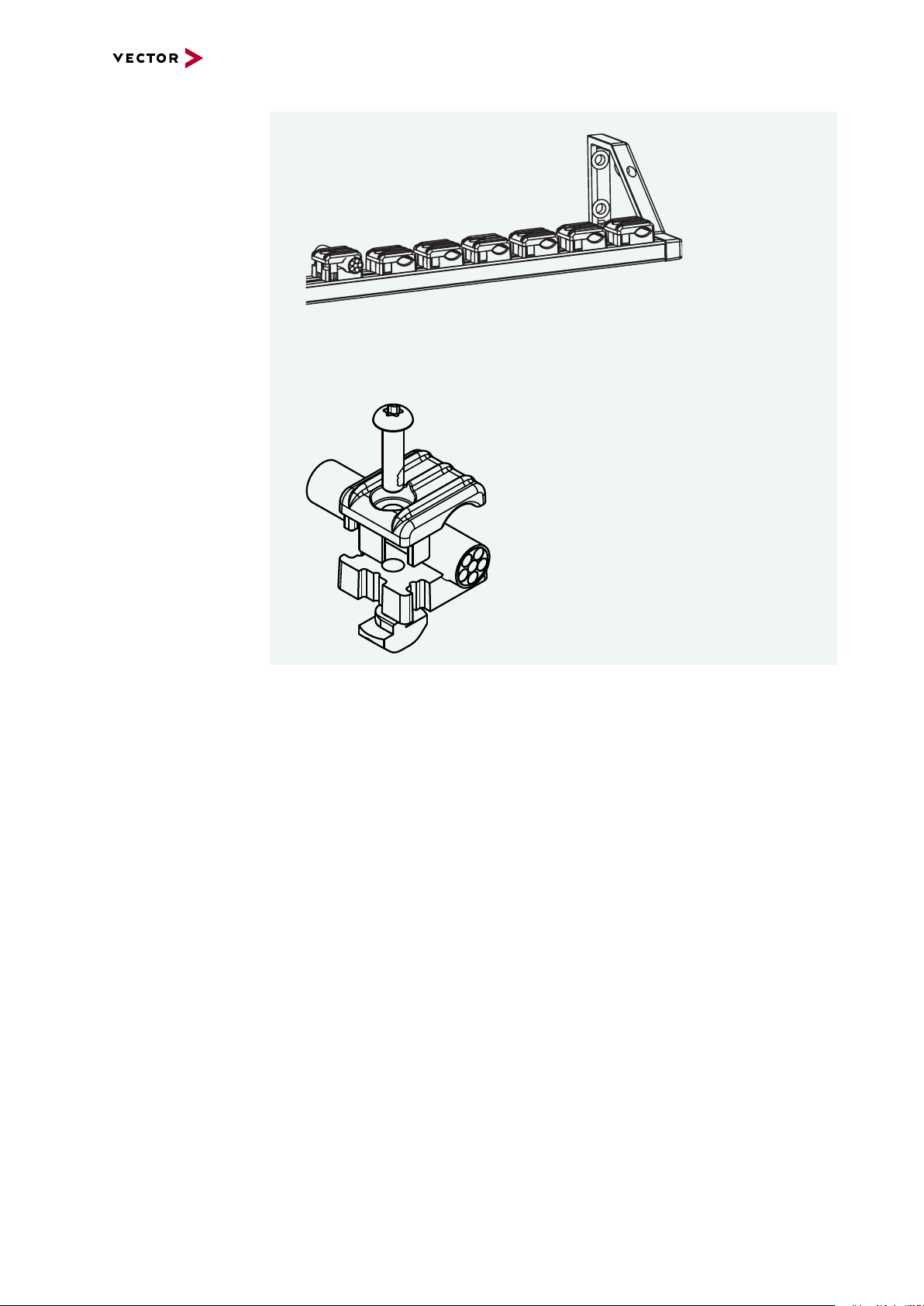
7 VN5240
7. Repeat the steps with all other clamps.
8. Finally, lead the individual cables through the clamps and tighten the individual
clamps depending on the cable (Torx10).
VN5000 Manual Version 2.5 93
Page 94

8 VN5650
8 VN5650
In this chapter you find the following information:
8.1 Scope of Delivery 95
8.2 Introduction 95
8.3 Connectors 97
8.3.1 Front Side 97
8.3.2 Back Side 98
8.4 LEDs 102
8.5 Technical Data 103
8.5.1 Overview 103
8.5.2 Temperature Shutdown 104
8.5.3 Electrical Isolation 105
8.5.4 Network Features 107
8.6 Accessories 109
8.6.1 VSH Cable Guard 216 110
VN5000 Manual Version 2.5 94
Page 95
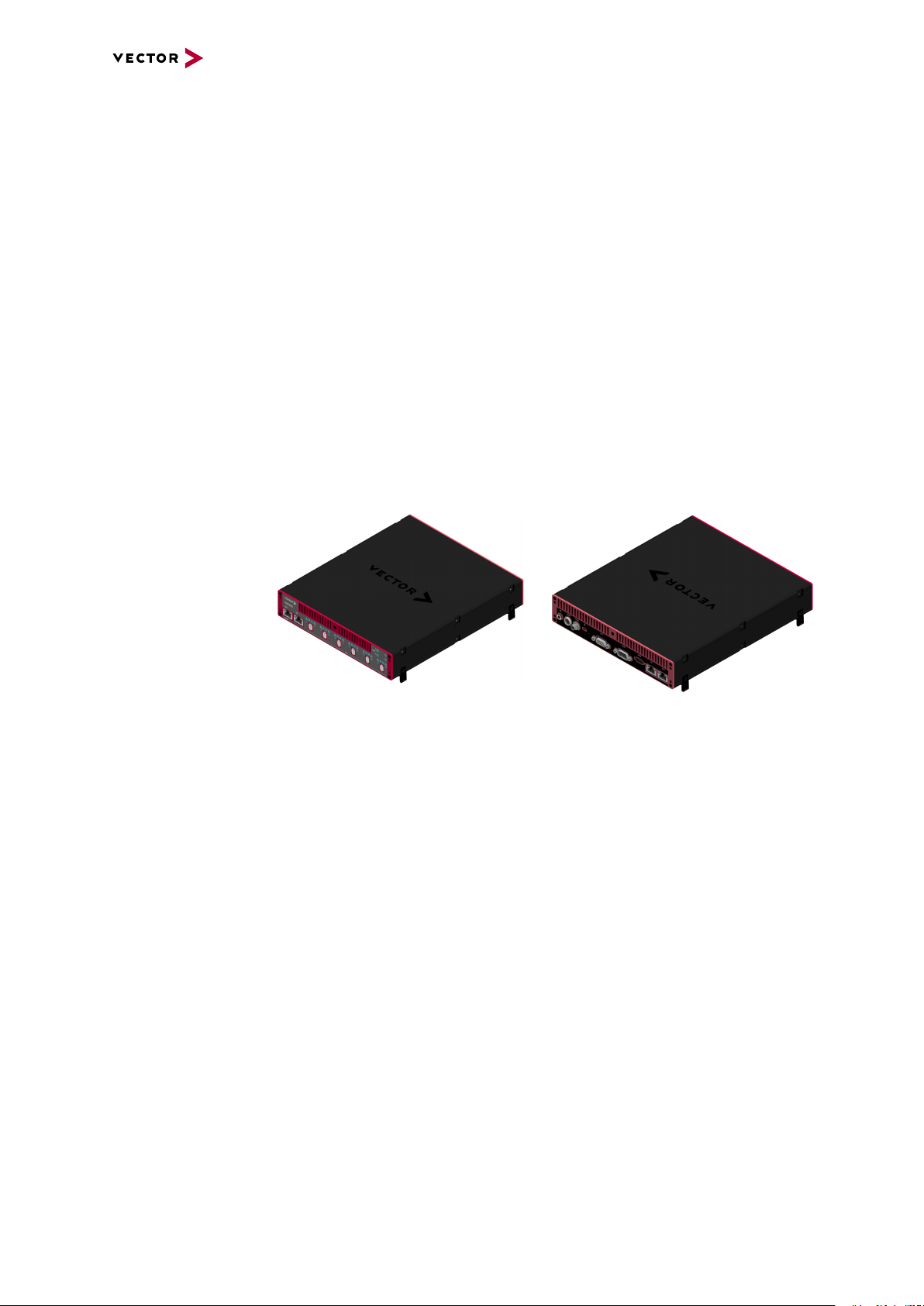
8 VN5650
8.1 Scope of Delivery
Contents The delivery includes:
► 1x VN5650 Ethernet/CAN Interface
► 1x Vector power supply ODU Connector / Bunch Plugs (part number 05069)
► 1x Ethernet cable CAT6A (2m)
► 1x USB Cable 3.1 Type A-C (Dual Screw Lock)
8.2 Introduction
About the VN5650 The VN5650 is a powerful Ethernet interface supporting 100/1000BASE-BASE-T1 on
12 ports. It is suitable for synchronous monitoring of Ethernet networks with other bus
systems. In addition, the VN5650 can provide optimal network access for residual
bus simulations and can be used for frame, load and fault generation during tests.
Thanks to its robust housing and the various mounting and stacking capabilities, the
device is ideally suited for use in vehicles. Ethernet (10GBASE-T) or USB 3.0 is used
as the interface to the computer.
Figure 43: VN5650 Ethernet Interface
Highlights Features of the VN5650:
► 12x user port 100BASE-T1/ 1000BASE-T1
► 2x infrastructure port 10/100/1000BASE-T(X)
► 2x infrastructure port 1G/2.5G/5G/10GBASE-T
usable:
- as uplink to host PC
- as an alternative user port (e.g. to analyze traffic of a 100BASE-
TX/10000BASE-T link)
- mirroring port
► 2x user channel CAN FD supporting up to 8 Mbit/s
► 1x Analog input
► 2x Digital input
► 1x Digital output (open collector)
► 2x Digital input/output, e.g. for DoIP Activation Line (ISO/DIS 13400-3)
► Host connection USB 3.1 Gen 1 or Ethernet (10GBASE-T)
► Onboard Ethernet TAPs to link between two Ethernet ports
► Onboard Vector Ethernet Switch IP supporting free segmentation
► New hardware configuration concept for flexible configuration
► Usable without host-connection to interconnect ECUs
- Self-configuration after power-up
► Hardware filtering of Ethernet packets on protocol base
VN5000 Manual Version 2.5 95
Page 96

8 VN5650
VN5650
VNm odul e60 4 AE1G
BCM8988 3
4 x 100BASE-T1/
1000BASE -T1
VNmodule 60 4AE1G VNmodule 60 4AE1G
2 x CAN
Analog/
Digital
IO
USB 3 .0
PWR SYNC
10G 1G
10G 1G
BCM8988 3 BCM8 9883
4 x 100BASE-T1/
1000BASE -T1
4 x 100BASE-T1/
1000BASE -T1
► Hardware synchronization to other Vector interfaces via
- IEEE 1588 (PTP)
- software synchronization (typ. 50µs accuracy)
- hardware synchronization (1µs accuracy)
► Multi-application support (different tools can share an Ethernet port at the same
time)
► Support of 3rd party tools with free XL Driver Library
► Provides high precision time stamped Ethernet/CAN frames (< 20 ns precision)
► Device is designed for in-vehicle applications:
- Robust housing with various mounting possibilities
- Form-factor fits perfect two times in a standard 19-inch rack system
- Extended power supply range (8V…32V)
- Extended temperature-range (-40°C...+65°C)
- Low-power stand-by mode (only 2mA power consumption)
- Onboard/configurable high frequency Ethernet bypass relays ensure a closed
TAP connection between two ECUs while the VN5650 is not powered
Figure 44: Ports overview
VN5000 Manual Version 2.5 96
Page 97

8.3 Connectors
12345
109876
8.3.1 Front Side
Device connectors
Figure 45: Connectors on the Ethernet side
► Host 10G (RJ45)
Connect your PC and the VN5650 via RJ45 to use the device with measurement
applications (e. g. CANoe, CANalyzer) in a network setup.
Note
10Gbps Ethernet connections exhibit an increased sensitivity to EMI.
Data integrity is guaranteed by use of protocols which may reduce data throughput.
8 VN5650
► 1G (RJ45)
Infrastructure port with different possible configurations:
- mirror port
- alternative analysis port
► Ethernet 1...12 (ix Industrial)
ix Industrial connectors for 100BASE-T1/1000BASE-T1 (e.g. Harting ix Industrial
type 10A-1). Each connector has two Ethernet ports (A and B). Use cables of the
Vector AEcable 2Y family to access both ports on separate connectors (different
plug systems available)
Pin Assignment
1 CH2 P
2 CH2 N
3 Not connected
4 Not connected
5 Not connected
6 CH1 P
7 CH1 N
8 Not connected
9 Not connected
10 Not connected
VN5000 Manual Version 2.5 97
Page 98

8.3.2 Back Side
1
2
3 1
2
Device connectors
8 VN5650
Figure 46: Connectors on the USB side
► Functional Earth (FE)
Optional connection of housing ground to system ground.
► Power (ODU)
For power supply, the VN5650 has a two-pin ODU connector (MINI-SNAP size 1,
type GF1L0C-P02RP00-0000). Attach the enclosed power cable to power up the
unit (matching ODU connector type S11L0C-P02NPL0-6200).
Pin Assignment
1 Power supply (8V ... 32V)
2 Ground
► Sync (Binder)
The VN5650 has a sync connector (Binder type 711) which can be used for time
synchronization of different Vector devices (see section Time Synchronization on
page 135).
Pin Assignment
1 Terminal 15
2 Synchronization line
3 Ground Sync
► Kensington Lock
Mounting of Nano Kensington (NanoSaver).
► Reset
If the device configuration is corrupted, start it with pushed reset button.
VN5000 Manual Version 2.5 98
Page 99

5
4
3
2
1
6
7
8
9
Digital Input 1
Not connected
Digital Output
Digital GND
Analog GND
Digital Input 0
Digital In/Out 1
Digital In/Out 0
Analog Input
Internal
Digital Input/Ouput
Isolation
455R
Ri
50R
50R
Vcc
GND_ISO
Passive
Network
From Processor
To Processor
GND_ISO
10k
To Processor
Digital GND
Vcc
Digital GND Digital GND
Digital Input 0/1
Isolation
20k
Vref
200k
OUT
IN-
IN+
33 V
370 pF
From Processor
Digital Output
Digital GND
Isolation
33 V
370 pF
interconnection of
digital in/out 0/1
8 VN5650
► IO (D-SUB)
The VN5650 has a D-SUB9 connector for dedicated digital input/output tasks. The
pin assignment is as follows:
Pin Assignment
1 Analog input
2 Digital input/output 0
3 Digital input/output 1
4 Digital input 0
5 Digital input 1
6 Analog GND
7 Not connected
8 Digital output
9 Digital GND
Figure 47: Digital input /output
Internal
interconnection of
digital input 0/1
Figure 48: Digital input 0/1
Internal
interconnection of
digital output
VN5000 Manual Version 2.5 99
Figure 49: Digital output
Page 100

Internal
To Processor
Analog GND
Vcc
Analog Input
100k
1M
33 V
370 pF
Analog GND
22 pF
ADC
15k
10k
Analog GND
OUT
IN+
IN-
Isolation
INOUT
interconnection of
analog input
8 VN5650
Figure 50: Analog input
Extended measuring
range of the
In normal operation, voltages up to 18 V can be applied and measured at the analog
input. The cutoff frequency fc(-3 dB) for AC voltages is approx. 7.2 kHz.
analog input
For measurements above 18 V (max. 50 V), an external series resistor has to be
applied to the analog input. The series resistor R
voltage U
to be measured and can be calculated as follows:
input
depends on the maximum input
ext
The cutoff frequency for AC voltages is also affected by the external series resistor:
Examples 24 V 32 V 36 V 48 V
R
ext
R
(E96) 374 kΩ
ext
367 kΩ 856 kΩ 1100 kΩ 1833 kΩ
(24.12 V)
866 kΩ
(32.17 V)
1100 kΩ
(36.00 V)
1870 kΩ
(48.60 V)
fc(-3 dB) 1148Hz 496Hz 390Hz 230Hz
VN5000 Manual Version 2.5 100
 Loading...