

Page 1
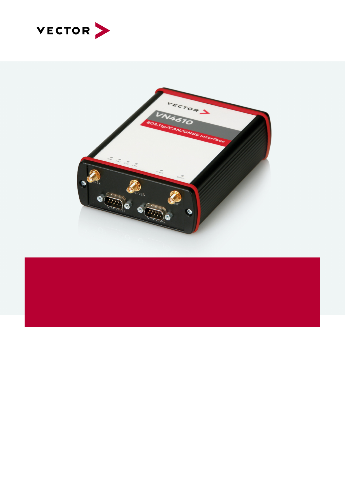
VN4610
Manual
Version 1.3|English
vector.com
Page 2

Imprint
Vector Informatik GmbH
Ingersheimer Straße 24
D-70499 Stuttgart
The information and data given in this user manual can be changed without prior notice. No part of this manual may be reproduced in any
form or by any means without the written permission of the publisher, regardless of which method or which instruments, electronic or
mechanical, are used. Alltechnicalinformation, drafts, etc. are liable to law of copyright protection.
© Copyright 2021, Vector Informatik GmbH. All rights reserved.
Page 3

Contents
Contents
1 Introduction 6
1.1 About this User Manual 7
1.1.1 Warranty 8
1.1.2 Registered Trademarks 8
1.2 Important Notes 9
1.2.1 Safety Instructions and Hazard Warnings 9
1.2.1.1 Proper Use and Intended Purpose 9
1.2.1.2 Hazards 10
1.2.2 Disclaimer 10
2 VN4610 802.11p/CAN/GNSS Interface 11
2.1 Scope of Delivery 12
2.2 Introduction 12
2.3 Accessories 13
3 Examples of Usage 14
3.1 General Use Cases 15
4 Device Description 16
4.1 Connectors Bus Side 17
4.2 Connectors USB Side 18
4.3 LEDs 21
4.4 Technical Data 22
5 Getting Started 23
5.1 Driver Installation 24
5.2 Loop Tests 26
5.2.1 CAN 27
6 Vector Hardware Configuration 29
6.1 General Information 30
6.2 Tool Description 31
6.2.1 Introduction 31
6.2.2 Tree View 32
7 Time Synchronization 35
7.1 General Information 36
VN4610 Manual Version 1.3 3
Page 4

Contents
7.2 Software Sync 38
7.2.1 General Information 38
7.2.2 Configuration 39
7.3 Hardware Sync 40
7.3.1 General Information 40
7.3.2 Configuration 42
7.4 Precision Time Protocol Sync 43
7.4.1 General Information 43
7.4.2 Supported Features 43
7.4.3 Network Topology 44
7.4.4 Configuration 45
7.5 GNSS Sync 46
7.5.1 General Information 46
7.5.2 Configuration 47
7.6 Protocol Combinations 48
7.7 Use Cases and Configuration Examples 49
7.7.1 GNSS Synchronization 49
7.7.2 4.2 IEEE1588 Synchronization 50
7.7.3 Hardware Synchronization 51
7.8 Compatibility 52
7.8.1 Vector Software 52
7.8.2 Device Drivers 52
7.9 Troubleshooting 53
8 Ethernet Host Connections 54
8.1 General Hints 55
8.2 Getting Started 56
8.2.1 Connecting the Device 56
8.2.2 Changing the IP Address 58
8.3 Windows Network Throttling 60
8.3.1 Issue 60
8.3.2 Solution 60
8.4 Jumbo Frames 61
8.4.1 Issue 61
8.4.2 Solution 61
8.5 Interrupt Moderation Rate 62
8.5.1 Issue 62
8.5.2 Solution 62
8.6 Known Issues with 3rd Party Hardware 63
VN4610 Manual Version 1.3 4
Page 5

Contents
8.6.1 Intel I218 / I219 Network Cards 63
VN4610 Manual Version 1.3 5
Page 6

1 Introduction
1 Introduction
In this chapter you find the following information:
1.1 About this User Manual 7
1.1.1 Warranty 8
1.1.2 Registered Trademarks 8
1.2 Important Notes 9
1.2.1 Safety Instructions and Hazard Warnings 9
1.2.2 Disclaimer 10
VN4610 Manual Version 1.3 6
Page 7
1 Introduction
1.1 About this User Manual
Conventions In the two following charts you will find the conventions used in the user manual
regarding utilized spellings and symbols.
Style Utilization
bold Blocks, surface elements, window- and dialog names of the soft-
ware. Accentuation of warnings and advices.
[OK]
File|Save
Source Code
Hyperlink Hyperlinks and references.
<CTRL>+<S> Notation for shortcuts.
Symbol Utilization
File name and source code.
This symbol calls your attention to warnings.
Push buttons in brackets
Notation for menus and menu entries
Here you can obtain supplemental information.
Here you can find additional information.
Here is an example that has been prepared for you.
Step-by-step instructions provide assistance at these points.
Instructions on editing files are found at these points.
This symbol warns you not to edit the specified file.
VN4610 Manual Version 1.3 7
Page 8

1.1.1 Warranty
1 Introduction
Restriction
of warranty
We reserve the right to change the contents of the documentation and the software
without notice. Vector Informatik GmbH assumes no liability for correct contents or
damages which are resulted from the usage of the documentation. We are grateful for
references to mistakes or for suggestions for improvement to be able to offer you
even more efficient products in the future.
1.1.2 Registered Trademarks
Registered
trademarks
All trademarks mentioned in this documentation and if necessary third party
registered are absolutely subject to the conditions of each valid label right and the
rights of particular registered proprietor. All trademarks, trade names or company
names are or can be trademarks or registered trademarks of their particular proprietors. All rights which are not expressly allowed are reserved. If an explicit label of
trademarks, which are used in this documentation, fails, should not mean that a name
is free of third party rights.
► Windows, Windows 7, Windows 8.1, Windows 10
are trademarks of the Microsoft Corporation.
VN4610 Manual Version 1.3 8
Page 9

1.2 Important Notes
1.2.1 Safety Instructions and Hazard Warnings
Caution!
In order to avoid personal injuries and damage to property, you have to read and
understand the following safety instructions and hazard warnings prior to installation and use of this interface. Keep this documentation (manual) always near the
interface.
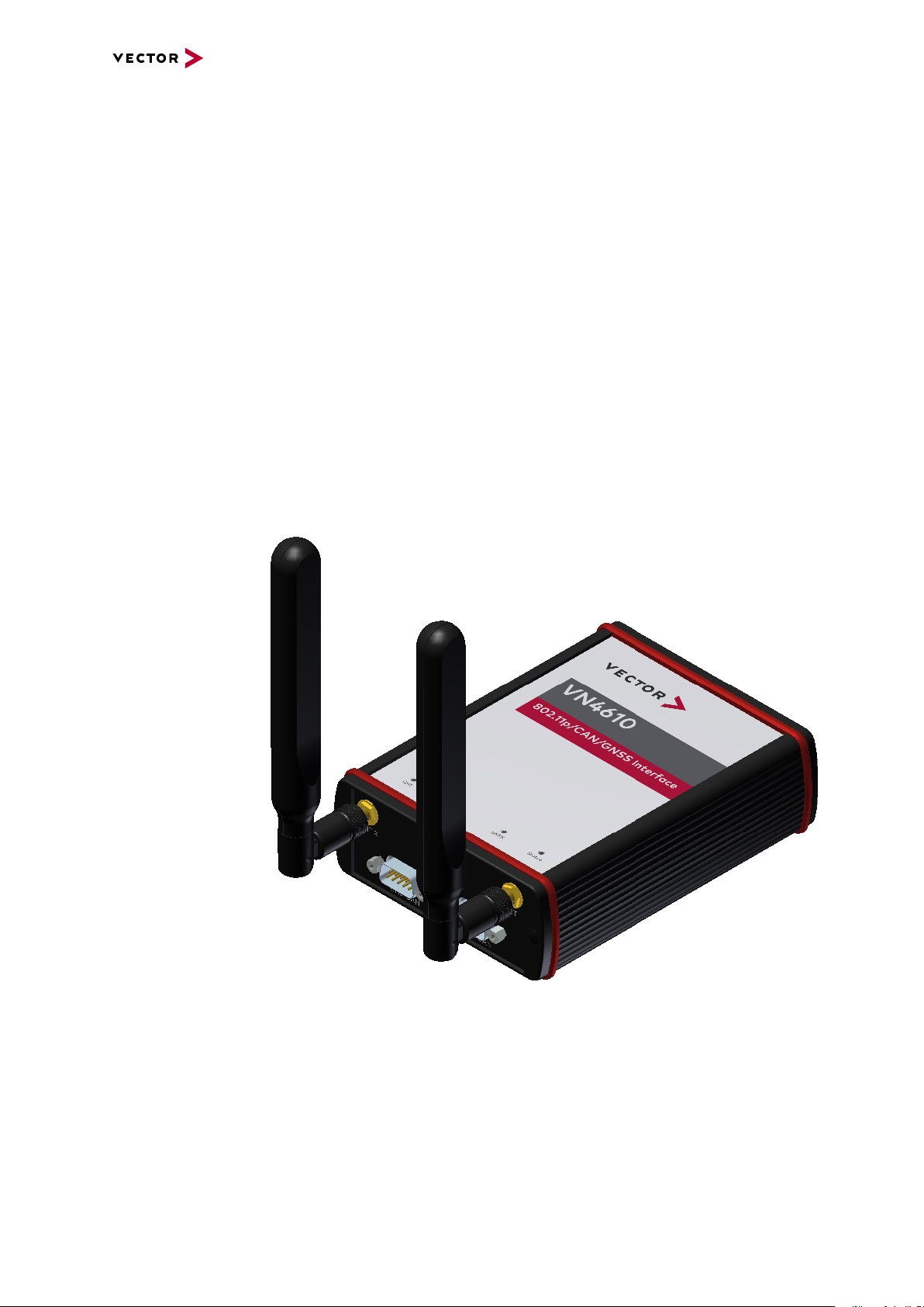
Caution!
Do not operate the device without antennas! To avoid physical damage to the
device, please attach the provided antennas to the device before operation!
1.2.1.1 Proper Use and Intended Purpose
1 Introduction
Caution!
The interface is designed for analyzing, controlling and otherwise influencing control systems and electronic control units. This includes, inter alia, bus systems like
CAN, LIN, K-Line, MOST, FlexRay, Ethernet, BroadR-Reach and/or ARINC 429.
The interface may only be operated in a closed state. In particular, printed circuits
must not be visible. The interface may only be operated (i) according to the instructions and descriptions of this manual; (ii) with the electric power supply designed
for the interface, e.g. USB-powered power supply; and (iii) with accessories manufactured or approved by Vector.
The interface is exclusively designed for use by skilled personnel as its operation
may result in serious personal injuries and damage to property. Therefore, only
those persons may operate the interface who (i) have understood the possible
effects of the actions which may be caused by the interface; (ii) are specifically
trained in the handling with the interface, bus systems and the system intended to
be influenced; and (iii) have sufficient experience in using the interface safely.
The knowledge necessary for the operation of the interface can be acquired in
work-shops and internal or external seminars offered by Vector. Additional and
interface specific information, such as „Known Issues“, are available in the „Vector
KnowledgeBase“on Vector´s website at www.vector.com. Please consult the
„Vector KnowledgeBase“for updated information prior to the operation of the interface.
VN4610 Manual Version 1.3 9
Page 10

1.2.1.2 Hazards
1 Introduction
Caution!
The interface may control and/or otherwise influence the behavior of control systems and electronic control units. Serious hazards for life, body and property may
arise, in particular, without limitation, by interventions in safety relevant systems
(e.g. by deactivating or otherwise manipulating the engine management, steering,
airbag and/or braking system) and/or if the interface is operated in public areas
(e.g. public traffic, airspace). Therefore, you must always ensure that the interface
is used in a safe manner. This includes, inter alia, the ability to put the system in
which the interface is used into a safe state at any time (e.g. by „emergency shutdown“), in particular, without limitation, in the event of errors or hazards.
Comply with all safety standards and public regulations which are relevant for the
operation of the system. Before you operate the system in public areas, it should
be tested on a site which is not accessible to the public and specifically prepared
for performing test drives in order to reduce hazards.
1.2.2 Disclaimer
Caution!
Claims based on defects and liability claims against Vector are excluded to the
extent damages or errors are caused by improper use of the interface or use not
according to its intended purpose. The same applies to damages or errors arising
from insufficient training or lack of experience of personnel using the interface.
VN4610 Manual Version 1.3 10
Page 11

2 VN4610 802.11p/CAN/GNSS Interface
2 VN4610 802.11p/CAN/GNSS Interface
In this chapter you find the following information:
2.1 Scope of Delivery 12
2.2 Introduction 12
2.3 Accessories 13
VN4610 Manual Version 1.3 11
Page 12
2 VN4610 802.11p/CAN/GNSS Interface
2.1 Scope of Delivery
Contents The delivery includes:
► 1x VN4610 802.11p/CAN/GNSS Interface
► 2x 5.9 GHz DSRC antenna (part no. 07204)
► 1x GNSS antenna (part no. 07205)
► 1x Power supply (part no. 05024)
► 1x USB 2.0 cable (part no. 05011)
2.2 Introduction
About the VN4610 The VN4610 is a powerful interface with USB PC connection for accessing IEEE
802.11p and CAN FD networks. The dedicated short range communication (DSRC) is
based on the IEEE802.11p standard, which transmits/receives frames in the 5.9 GHz
frequency range. The VN4610 supports the unfiltered receiving and sending of IEEE
802.11p frames used for the implementation of Car2x/V2x applications. It is possible
to synchronize the received radio frames with CAN FD messages. The built-in GNSS
receiver supplies the absolute UTC time and current position.
Figure 1: VN4610 802.11p/CAN Interface (bus side)
Overview of Advantages
► Sending/receiving frames according to IEEE 802.11p
► Two configurable IEEE 802.11p WLAN channels
► Unfiltered forwarding of IEEE 802.11p data packets to the application
► Adjustable communication parameters such as radio channel selection, band-
width, transmission power, modulation type and protocol format LPD/EPD
VN4610 Manual Version 1.3 12
Page 13

2 VN4610 802.11p/CAN/GNSS Interface
► Two CAN high-speed channels CAN (FD) capable
► GNSS receiver provides current position and time
► Precise time stamp based on GNSS time
► Time synchronisation with PTP according to IEEE 1588 standard (future Release)
► VN4610 and CANoe.Car2x/CANalyzer.Car2x are optimally matched to each
other
► Synchronization with several interfaces and with other bus systems (Ethernet,
CAN, LIN, FlexRay, ...)
► Robust housing, power supply and temperature range ideal for automotive and
industrial applications
► IO port with digital/analog in/out
► Ethernet with IEEE802.3: 100BASE-TX and 1000BASE-T
► Support of customer CAN/DAIO applications via XL-Driver Library (XL-API)
► Multi-application support (simultaneous operation of different applications on one
channel, e.g. CANoe and CANape)
► High time stamp accuracy
► Time synchronization of multiple devices and with other bus systems (CAN, LIN,
FlexRay, MOST, Ethernet)
► Software time synchronization
► Hardware time synchronization
► GNSS time synchronization to absolute UTC time
► Time synchronization with PTP according to IEEE 1588 standard
► Connection to host PC via USB 2.0
► LEDs indicating status and activities
► External power supply, galvanically isolated
2.3 Accessories
Reference
Information on available accessories can be found in the separate accessories
manual on our website.
VN4610 Manual Version 1.3 13
Page 14

3 Examples of Usage
3 Examples of Usage
In this chapter you find the following information:
3.1 General Use Cases 15
VN4610 Manual Version 1.3 14
Page 15
3 Examples of Usage
VN4610
USB/Ethernet
IO
CAN(FD)
Data transfer
Sync
HW Sync
VNXXXX
Interfaces
CANoe.Car2X
CANalyzer.Car2X
IEEE 802.11p
CAN(FD)
Data
DSRC
Application
Car2X
V2x
GNSS
GNSS
GNSS
IEEE 802.11p
3.1 General Use Cases
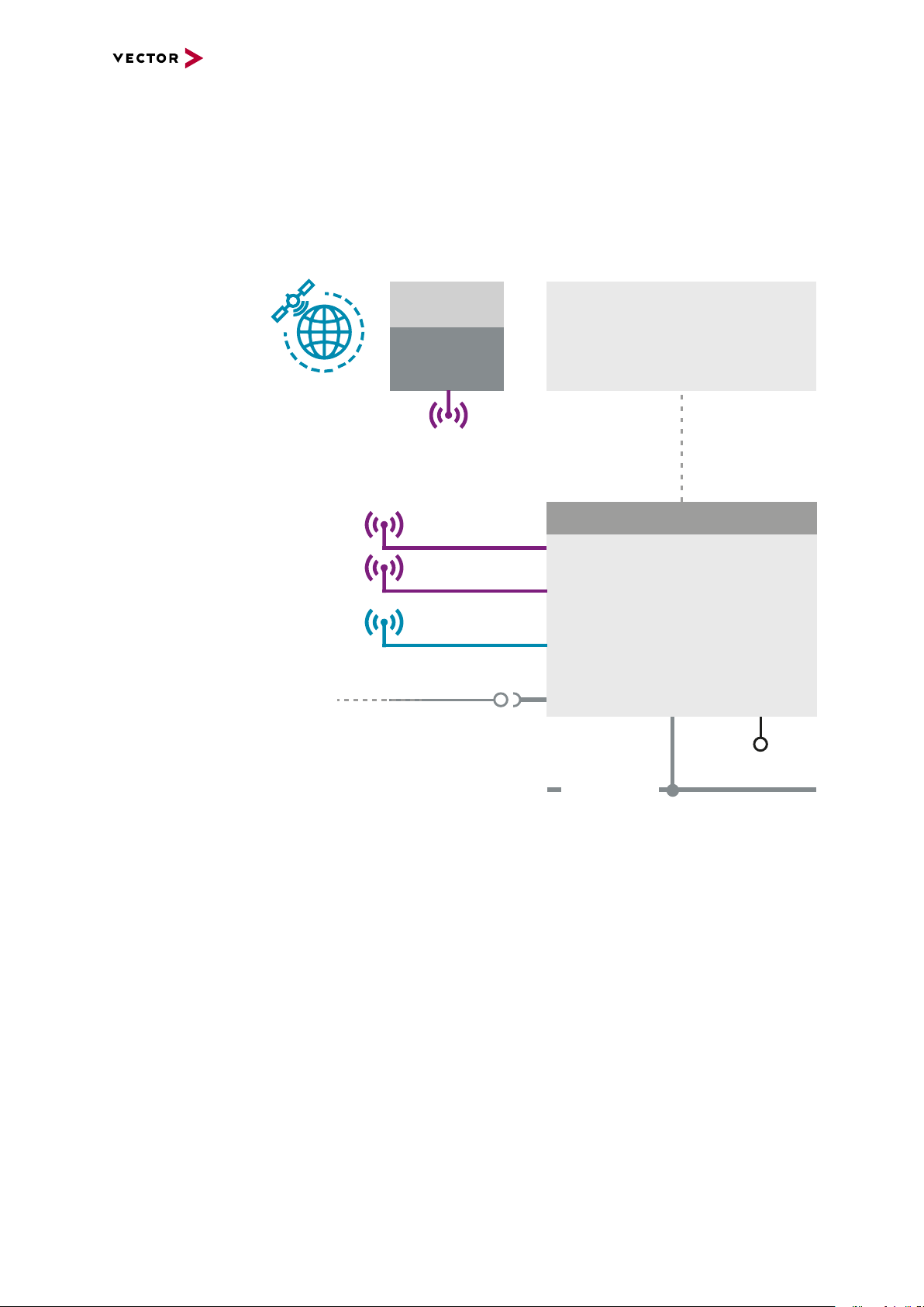
Analysis The VN4610 forwards all received radio frames of the two radio channels unfiltered to
the test tool for analysis. Therefore, frames can also be analyzed which would berejected by a ECU due to timing, geo information orprotocol errors caused by
Car2x/V2x. Since the time stampsof the messages on the bus channels are synchronized intime, latency measurements can also be carried out.
Simulation/
Stimulation
GNSS Receiver The VN4610 provides precise position, time and speed information that can be used
Time
synchronization
Figure 2: General use cases
CANoe.Car2x together with the VN4610 offers a perfectly coordinated solution for creating an environment stimulation for testing Car2x/V2x applications. The VN4610
sends the transmitted frames, whereby the communication parameters can be easily
and individually configured for the different tests.
by the application as test stimulus or for documentation. In addition, the absolute
GNSS timestamps can be used to synchronize recordings of distributed measurements for subsequent analysis. Additionally, the VN4610 can act as IEEE 1588
time master and provide the GNSS time in a network (in a future release).
The VN4610 enables precise time synchronization with PTP according to IEEE1588
standard. The device can be configured e.g. as PTP master with UTC time base,
which is provided by the built-in GNSS receiver.
VN4610 Manual Version 1.3 15
Page 16

4 Device Description
4 Device Description
In this chapter you find the following information:
4.1 Connectors Bus Side 17
4.2 Connectors USB Side 18
4.3 LEDs 21
4.4 Technical Data 22
VN4610 Manual Version 1.3 16
Page 17
4.1 Connectors Bus Side
5
4
3
2
1
6
789
Device connectors
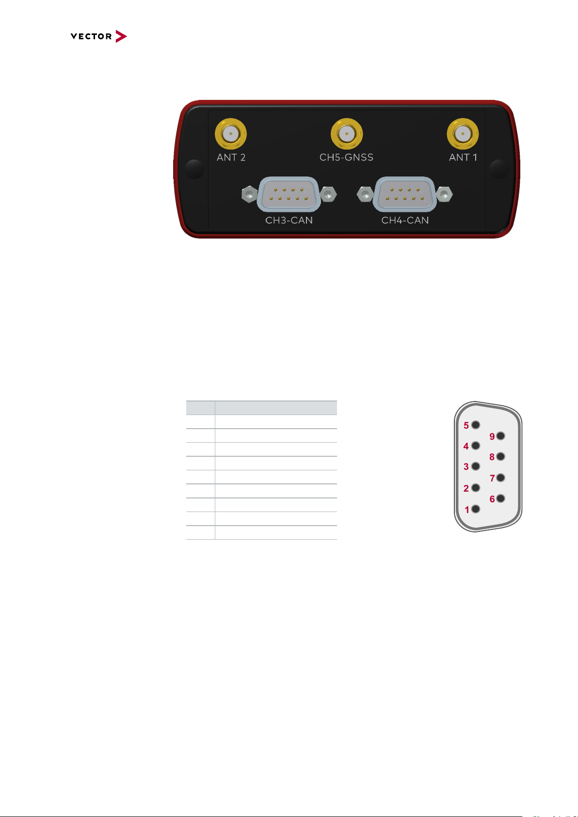
Figure 3: Connectors on the bus side
► Antenna 1/2 (CH1/CH2)
The VN4610 has two 802.11p channels which can be used to transmit and receive
data packages. Please attach the provided antennas before using these channels.
4 Device Description
► GNSS (CH5)
This channel can be used to receive GNSS time and position.
► D-SUB9 (CH3/CH4)
The VN4610 has two D-SUB9 connectors for CAN/CANFD. The channels are
electrically isolated. The pin assignment is as follows:
Pin Assignment
1 Not connected
2 1057G CAN Low
3 GND
4 Not connected
5 Not connected
6 Not connected
7 1057G CAN High
8 Not connected
9 Not connected
VN4610 Manual Version 1.3 17
Page 18
4.2 Connectors USB Side
1
Analog GND
1
2
3
4
5
9
8
7
6
6
Digital In 0
5
Digital Out
Digital GND
Analog In
4
Digital In 1
8
9
5 V Digital Out 7
To Processor
Digital GND
Vcc
Digital GND Digital GND
Digital Input 0/1
Isolation
20k
Vref
200k
OUT
IN-
IN+
33 V
370 pF
Device connectors
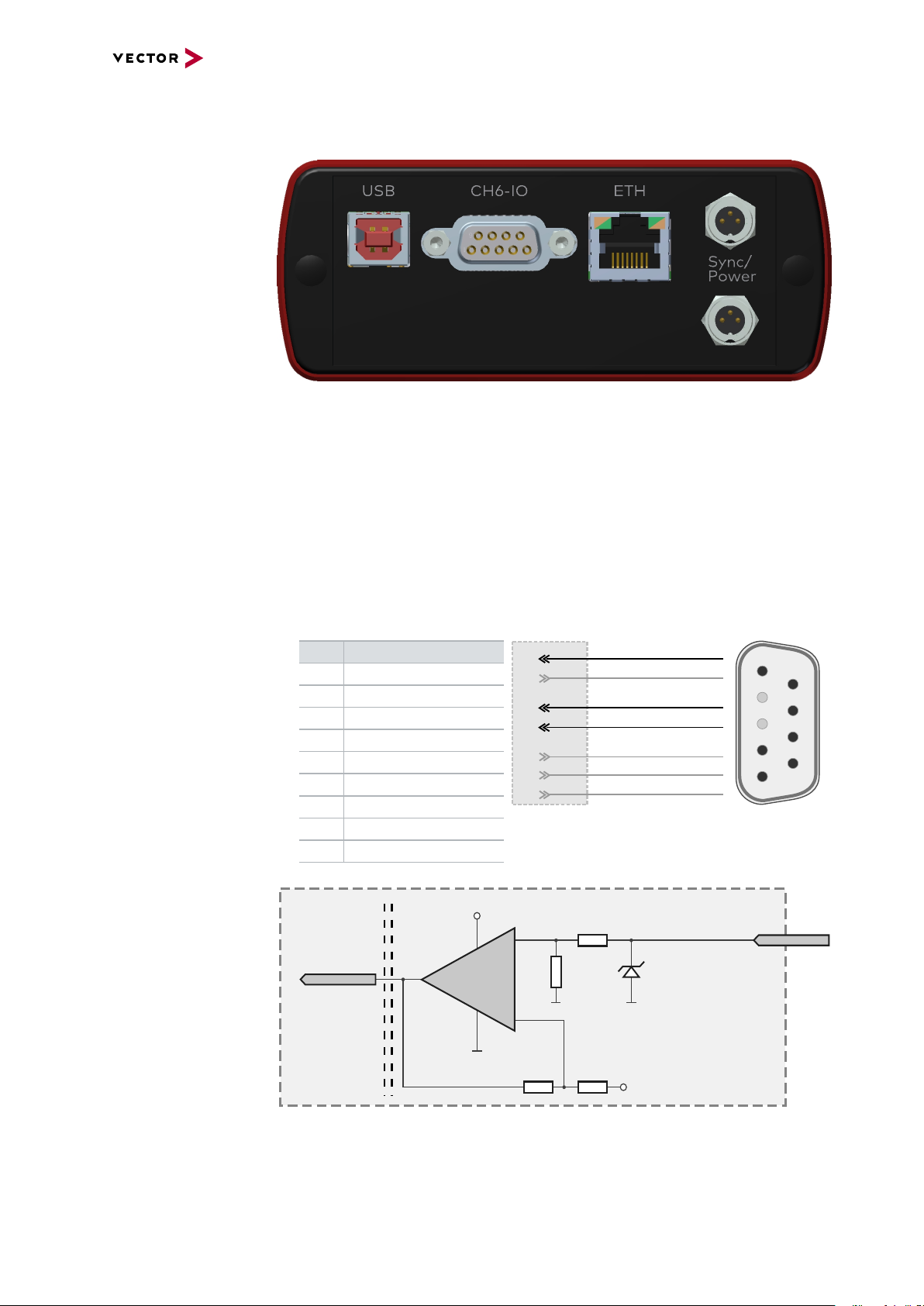
Figure 4: Connectors on the USB side
► USB
Connect your PC and the VN4610 over USB to install and to use the device with
measurement applications (CANoe, CANalyzer). Use the USB 2.0 compliant
cable found in the delivery (USB extension cables may generate faults between
the PC and the device). Connect the device directly to a USB port at your PC or
use a USB hub with its own power supply (self-powered).
4 Device Description
Internal
interconnection of
digital input 0/1
► D-SUB9 (CH6)
The VN4610 has a D-SUB9 connector for dedicated digital input/output tasks. The
pin assignment is as follows:
Pin Assignment
1 Analog input
2 Not connected
3 Not connected
4 Digital input 0
5 Digital input 1
6 Analog GND
7 5V digital output
8 Digital output
9 Digital GND
Figure 5: Digital input 0/1
VN4610 Manual Version 1.3 18
Page 19
Internal
From Processor
Digital Output
Digital GND
Isolation
33 V
370 pF
To Processor
Analog GND
Vcc
Analog Input
100k
1M
33 V
370 pF
Analog GND
22 pF
ADC
15k
10k
Analog GND
OUT
IN+
IN-
Isolation
INOUT
5 V Digital Output
100
From Processor
Digital GND
Digital GND
5V ISO IO
Digital GND
100 nF
interconnection of
digital output
Internal
interconnection of
analog input
4 Device Description
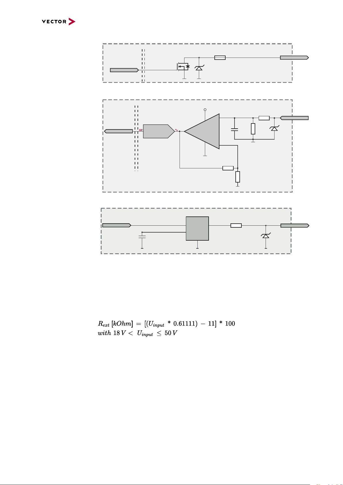
Figure 6: Digital output
Internal
interconnection of
5V digital output
Extended measuring
range of the analog
input
Figure 7: Analog input
Figure 8: 5V digital output
In normal operation, voltages up to 18 V can be applied and measured at the analog
input. The cutoff frequency fc(-3 dB) for AC voltages is approx. 7.2 kHz.
For measurements above 18 V (max. 50 V), an external series resistor has to be
applied to the analog input. The series resistor R
U
and can be calculated as follows:
input
depends on the input voltage
ext
VN4610 Manual Version 1.3 19
Page 20
4 Device Description
VCC
1
2
3
Power
1
2
3
Sync
GND
Sync
GND
Power/Sync
Power/Sync
SYNC
GND
Power
3
1
2
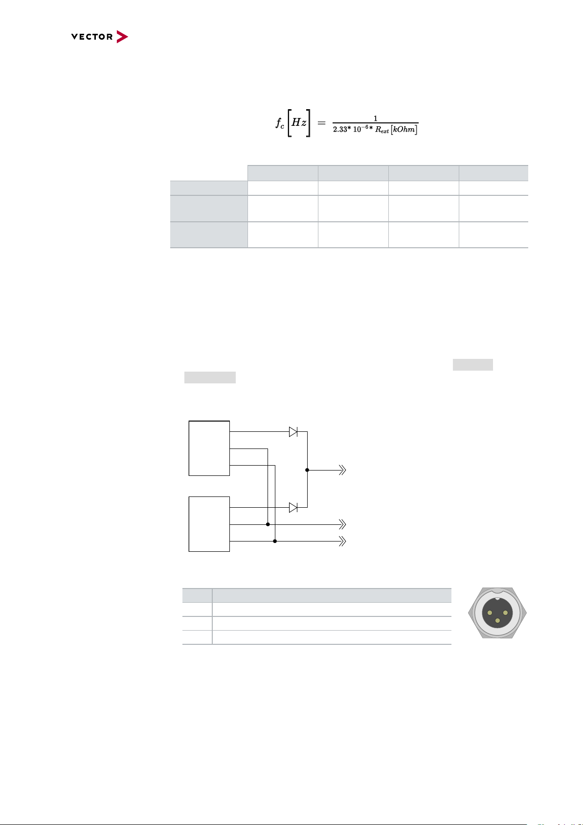
The cutoff frequency for AC voltages is also affected by the external series resistor:
Examples 24 V 32 V 36 V 48 V
R
ext
R
(E96) 374 kΩ
ext
367 kΩ 856 kΩ 1100 kΩ 1833 kΩ
(24.12 V)
866 kΩ
(32.17 V)
1100 kΩ
(36.00 V)
1870 kΩ
(48.60 V)
fc(-3 dB) 1148Hz 496Hz 390Hz 230Hz
Device connectors
(continued)
► Ethernet (RJ45)
Connect your PC and the VN4610 via this Ethernet port to install the device and
use it together with measurement applications (CANoe, CANalyzer).
► Power/Sync (Binder connector)
The VN4610 has two power/sync connectors (Binder type 711) which can be used
for time synchronization of different Vector devices (see section Time Synchronization on page 35) or for power. It does not matter which connector is used
to supply the device. For proper operation of the VN4610, an external power supply is required.
Figure 9: Internal wiring of the power/sync connector
Pin Assignment
1 Power supply (typ. 12 V)
2 Synchronization line
3 Ground
VN4610 Manual Version 1.3 20
Page 21

4.3 LEDs
4 Device Description
Figure 10: LEDs of the VN4610
► CH1/CH2
Multicolored channel LEDs indicating the WiFi activity.
Color Description
Green Data frames have been sent or receicved correctly.
Red Transmission errors during sending or receiving.
WiFi: T he flashing frequency depends on the bus load.
► CH3/CH4
Multicolored channel LED indicating the bus activity.
Color Description
Green Data frames have been sent or received correctly.
Orange CAN: Error frames have been sent or received.
Red CAN: Bus off.
CAN: The flashing frequency depends on the bus load.
► GNSS
Multicolored channel LED indicating the GNSS activity.
Color Description
Green ► On: SAT fix within the specified accuracy settings achieved.
► Flashing: SAT fix without reaching the specified accuracy settings.
Red ► On: No Satellite signal.
► Flashing: Satellite signal too weak.
► Status
Multicolored channel LED indicating the status..
Color Description
Green Device is ready for operation/running measurement.
Orange Initializing driver. Please wait.
Red Error. Device not working.
VN4610 Manual Version 1.3 21
Page 22

4.4 Technical Data
802.11p channels NXP SAF5100
GNSS channel uBlox NEO-M8U, supports GPS, GLONASS,
CAN/CAN FD channel 2x NXP TJA1057G
Ethernet channel IEEE 100BASE-TX/1000Base-T
Analog input 10 bit
Digital input Range 0 V...32 V
Digital output Open Drain
5V digital output 5V TTL output signal on D-SUB9 connector,
Time stamps Accuracy (within one device): 1 µs
PC interface USB 2.0 /
Time synchronization PTP according to IEEE1588-2008 standard
Average response time 250 μs
Input voltage 6 V … 50 V DC
Power consumption Approx. 7 W
Temperature range
(ambient temp. of the device)
Relative humidity
of ambient air
Dimensions (LxWxH) Approx. 111 mm x 157 mm x 45 mm
Weight Approx. 610 g
Housing Robust aluminium housing
Operating system
requirements
4 Device Description
depending on modulation type up to 27 Mbit/s
Beidou, Galileo; up to 3 systems at the same
time
CAN up to 2 Mbit/s.
CAN FD up to 8 Mbit/s.
Input 0 V...18 V (Ri = 1.1 MΩ)
Voltage tolerance up to 30 V
Schmitt trigger high 2.8 V, low 2.3 V
Input frequencies up to 1 kHz
External supply up to 32 V
Output frequency up to 1 kHz
Current max. 500 mA
Short circuit / over voltage protected
pin 7. GND reference of the signal is digital
GND on pin 9.
Accuracy software sync: typ. 50 µs
Accuracy hardware sync: typ. 1 µs
Ethernet IEEE 100Base-TX/1000Base-T
Operation: -40 °C ... +60 °C
Storage: -40 °C ... +85 °C
15 %...95 %, non-condensing
without antennas
Windows 7 SP1 (32 bit / 64 bit)
Windows 8.1 (32 bit / 64 bit)
Windows 10 (64 bit)
VN4610 Manual Version 1.3 22
Page 23

5 Getting Started
5 Getting Started
In this chapter you find the following information:
5.1 Driver Installation 24
5.2 Loop Tests 26
5.2.1 CAN 27
VN4610 Manual Version 1.3 23
Page 24
5.1 Driver Installation
Caution!
Do not operate the device without antennas! To avoid physical damage to the
device, please attach the provided antennas to the device before operation!
5 Getting Started
General
information
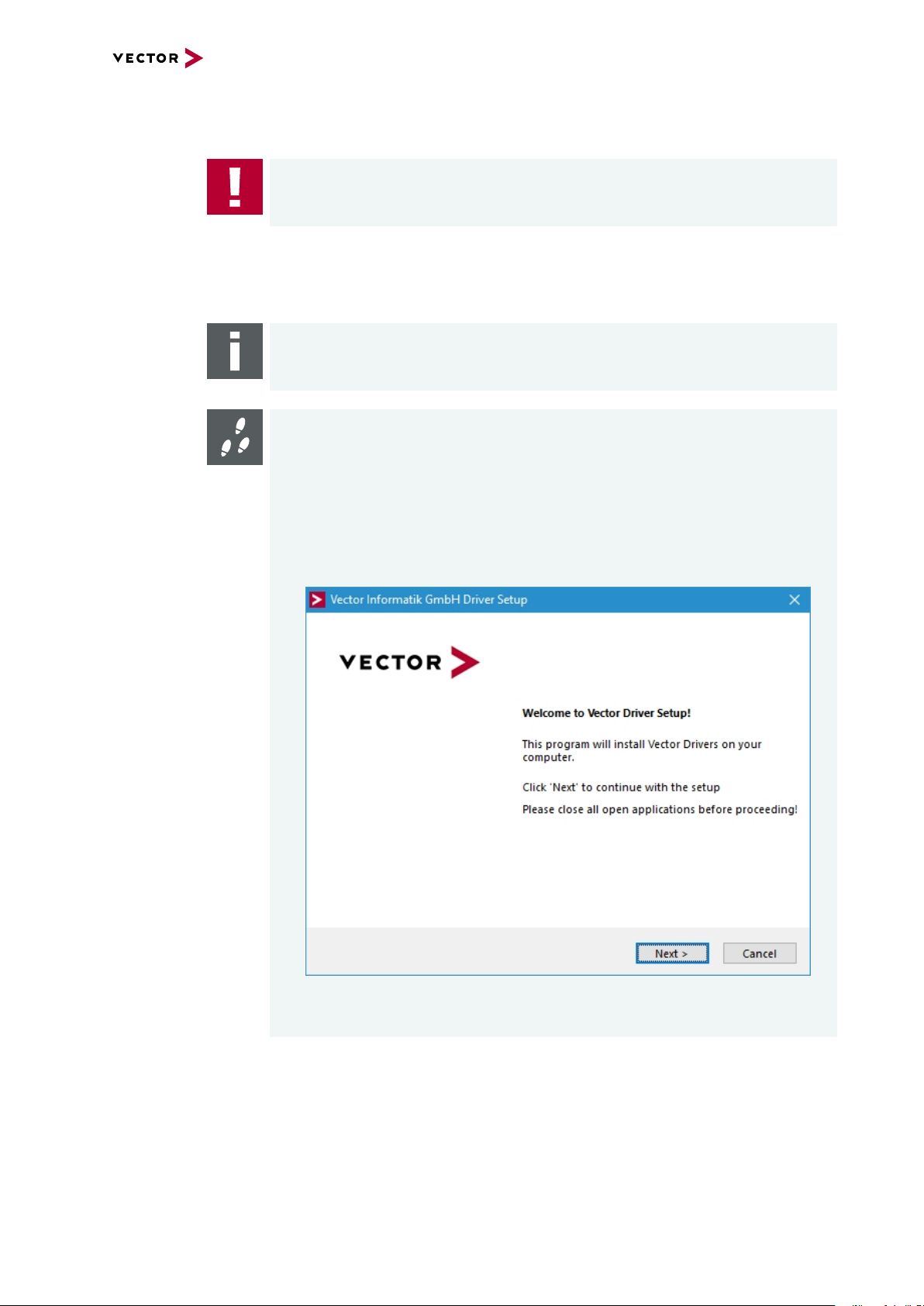
The Vector Driver Disk offers a driver setup which allows the installation or the
removal of Vector devices.
Note
Please note that you will need Administrator Rights for the following steps.
Step by Step Procedure
1. Execute the driver setup from the autostart menu or directly from
\Drivers\Setup.exe before the device is connected to the PC with the
included USB cable.
If you have already connected the device to the PC, the Windows found new
Hardware wizard appears. Close this wizard and then execute the driver setup.
2. Click [Next] in the driver setup dialog. The initialization process starts.
VN4610 Manual Version 1.3 24
Page 25

5 Getting Started
3. In the driver selection dialog, select your devices to be installed (or to be uninstalled).
4. Click [Install] to execute the driver installation, or [Uninstall] to remove existing drivers.
5. A confirmation dialog appears. Click [Close] to exit. After successful installation, the device is ready for operation and can be connected to the PC with the
included USB cable and powered by supplying external voltage (e.g. with an
appropriate cable offered by Vector).
VN4610 Manual Version 1.3 25
Page 26

5 Getting Started
5.2 Loop Tests
Operation test The test described here can be performed to check the functional integrity of the driver
and the device. This test is identical for Windows 7 / Windows 8.1 / Windows 10 and
independent of the used application.
VN4610 Manual Version 1.3 26
Page 27

5 Getting Started
5.2.1 CAN
Device test The operating test for CAN requires either two high-speed or two low-speed trans-
ceivers and can be executed as follows:
Step by Step Procedure
1. Connect two CAN channels with a suitable cable.
If two high-speed transceivers are being used, we recommend our
CANcable1 (CANcable0 for low-speed transceivers).
2. Start \Drivers\Common\Loop3.exe from the Vector Driver Disk.
This program accesses the Vector devices and transmits CAN messages.
3. Select the connected CAN channels of the device(s) to be tested.
VN4610 Manual Version 1.3 27
Page 28

5 Getting Started
4. Set the appropriate baudrate depending on the transceiver being used (highspeed max. 1,000,000 Bd, low-speed max. 125,000 Bd).
5. Click [Start].
6. You will see statistical data in the lower part of the window if the system has
been configured properly.
7. The test procedure can be terminated with the [Stop] button.
An OK should appear in the upper part of the window.
VN4610 Manual Version 1.3 28
Page 29

6 Vector Hardware Configuration
6 Vector Hardware Configuration
In this chapter you find the following information:
6.1 General Information 30
6.2 Tool Description 31
6.2.1 Introduction 31
6.2.2 Tree View 32
VN4610 Manual Version 1.3 29
Page 30

6.1 General Information
6 Vector Hardware Configuration
Executing Vector
Hardware Config
Control Panel
Windows 7
Control Panel
Windows 8.1
After the successful driver installation, you will find the configuration application
Vector Hardware in the Control Panel (see below). The tool gives you information
about the connected and installed Vector devices. There are also several settings that
can be changed.
Figure 11: Icon in Control Panel
► Category view
Windows Start | Control Panel | Hardware and Sound,
click Vector Hardware in the list.
► Symbols view
Windows Start | Control Panel,
click Vector Hardware in the list.
► Category view
<Windows key>+<X> | Control Panel | Hardware and Sound,
click Vector Hardware in the list.
► Symbols view
<Windows key>+<X> | Control Panel,
click Vector Hardware in the list.
Control Panel
Windows 10
► Category view
<Windows key>+<X> | Control Panel | Hardware and Sound,
click Vector Hardware in the list.
► Symbols view
<Windows key>+<X> | Control Panel,
click Vector Hardware in the list.
VN4610 Manual Version 1.3 30
Page 31

6.2 Tool Description
physical CH1
CAN
physical CH2
LIN
Vector Device 1
Vector Device 2
physical CH1
FlexRay
physical CH2
CAN
not assigned
l
ogical channel
CAN 1
Application
l
ogical channel
LIN 1
l
ogical channel
CAN 1
l
ogical channel
FlexRay 1
l
ogical channel
CAN 2
6.2.1 Introduction
Vector
Hardware Config
Figure 12: General view of Vector Hardware Config
6 Vector Hardware Configuration
Logical and physical
channels
Vector Hardware Config enables the channel configuration between installed Vector
devices and applications. Applications use so-called logical channels which are hardware independent and have to be assigned to real hardware channels.
Figure 13: Concept of channel assignments
VN4610 Manual Version 1.3 31
Figure 14: Channel assignment in Vector Hardware Config
Page 32

6.2.2 Tree View
6 Vector Hardware Configuration
Accessing
Vector devices
The tool is split into two windows. The left window has a tree view and lets you
access the installed Vector devices, the right window displays the details of the selection. The following nodes are available in the tree view:
Hardware The Hardware section lists the installed Vector devices. Each device item has phys-
ical channels which can be assigned to any number of logical channels (e.g.
CANalyzer CAN 1). A logical channel can be assigned to only one physical channel.
Figure 15: Hardware
Application In Application, all available applications are displayed in a tree view. According to
each application, the assignments of logical and physical channels are displayed in
the right part of the window. If no assignment exists, the information Not assigned
appears. The assignment can be edited via a right-click.
Figure 16: Application
VN4610 Manual Version 1.3 32
Page 33
6 Vector Hardware Configuration
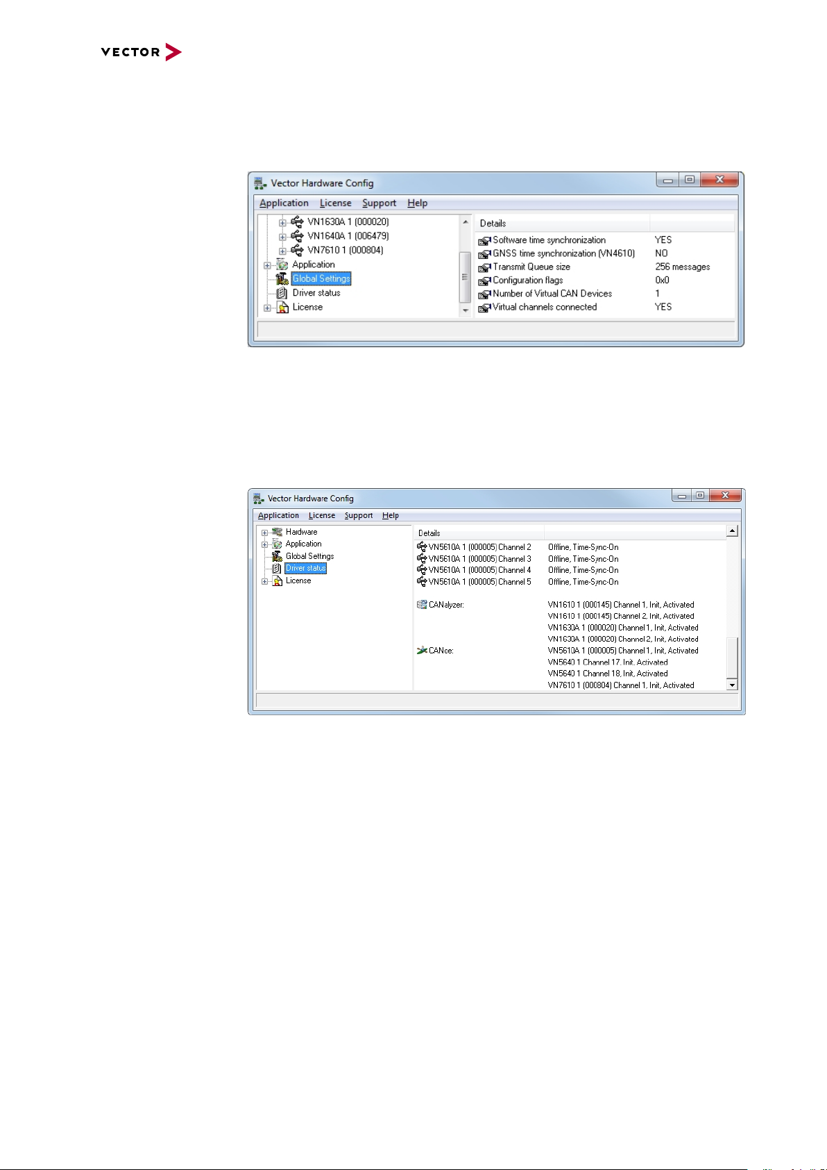
Global settings Global settings contains global device configuration possibilities, e.g. software time
synchronization, GNSS time synchronization, transmit queue size, configuration
flags or the number of virtual CAN devices.
Figure 17: Global settings
Driver status Driver status offers an overall status information of devices and applications cur-
rently in use. You can see whether the channels are connected to the bus (online/offline) and whether the time synchronization is activated or not (Time-Sync-On/TimeSync-Off).
Figure 18: Dr iver status
VN4610 Manual Version 1.3 33
Page 34

6 Vector Hardware Configuration
License The License section contains information on all current available licenses (Vector bus
devices, Vector License USB dongle devices).
Figure 19: License
Reference
You will find a detailed description of Vector Hardware Config in the online help
(Help | Contents).
VN4610 Manual Version 1.3 34
Page 35

7 Time Synchronization
7 Time Synchronization
In this chapter you find the following information:
7.1 General Information 36
7.2 Software Sync 38
7.2.1 General Information 38
7.2.2 Configuration 39
7.3 Hardware Sync 40
7.3.1 General Information 40
7.3.2 Configuration 42
7.4 Precision Time Protocol Sync 43
7.4.1 General Information 43
7.4.2 Supported Features 43
7.4.3 Network Topology 44
7.4.4 Configuration 45
7.5 GNSS Sync 46
7.5.1 General Information 46
7.5.2 Configuration 47
7.6 Protocol Combinations 48
7.7 Use Cases and Configuration Examples 49
7.7.1 GNSS Synchronization 49
7.7.2 4.2 IEEE1588 Synchronization 50
7.7.3 Hardware Synchronization 51
7.8 Compatibility 52
7.8.1 Vector Software 52
7.8.2 Device Drivers 52
7.9 Troubleshooting 53
VN4610 Manual Version 1.3 35
Page 36

7.1 General Information
CAN
Vector
CAN Interface
CH1
CH2
Time Stamp Clock
PC
CANalyzer/CANoe
USB
7 Time Synchronization
Time stamps
and events
Generating
time stamps
Time stamps are useful when analyzing incoming or outgoing data or event
sequences on a specific bus.
Figure 20: Time stamps of two CAN channels in CANalyzer
Each event which is sent or received by a Vector network interface has an accurate
time stamp. Time stamps are generated for each channel in the Vector network interface. The base for these time stamps is a common hardware clock in the device.
Figure 21: Common time stamp clock for each channel
If the measurement setup requires more than one Vector network interface, a synchronization of all connected interfaces and their hardware clocks is needed.
Due to manufacturing and temperature tolerances, the hardware clocks may vary in
speed, so time stamps of various Vector devices drift over time.
VN4610 Manual Version 1.3 36
Page 37

7 Time Synchronization
CAN
Ethernet
Vector
CH1 CH2
Time Stamp Clock
PC
Vector
Ethernet InterfaceCAN Interface
Time Stamp Clock
sec
0.000000
0.100376
0.200382
0.300372
0.400406
0.500593
0.600242
sec
0.000000
0.100383
0.200982
0.301456
0.402612
0.503885
0.604092
CANalyzer/CANoe
USB USB
Port 1 Port 2
Figure 22: Example of unsynchronized network interfaces. Independent time stamps drift apart
To compensate for these time stamp deviations between the Vector network interfaces, the time stamps can be either synchronized by software, hardware, PTP or
GNSS (see next section).
Note
The accuracy of the software, hardware, PTP or GNSS sync depends on the interface. Further information on specific values can be found in the technical data of
the respective devices.
VN4610 Manual Version 1.3 37
Page 38

7.2 Software Sync
CAN
Vector
CAN Interface
CH1 CH2
Time Stamp Clock
synchronization
by software (PC clock)
sec
0.000000
1.100356
1.200362
2.300362
2.400356
3.500353
3.600362
PC
sec
0.000000
1.100413
1.200421
2.300429
2.400419
3.500415
3.600420
PC clock
CANalyzer/CANoe
USB
Ethernet
Vector
Ethernet Interface
Port 1 Port 2
Time Stamp Clock
USB
7.2.1 General Information
7 Time Synchronization
Synchronization
by software
The software time synchronization is driver-based and available for all applications
without any restrictions. The time stamp deviations from different Vector network interfaces are calculated and synchronized to the common PC clock. For this purpose no
further hardware setup is required.
Figure 23: Time stamps of devices are synchronized to the PC clock
Note
Software time synchronization may lead to an increased latency for all connected
Vector network interfaces. If a use case requires low latency, deactivate this
option and use another synchronization mechanism.
VN4610 Manual Version 1.3 38
Page 39

7.2.2 Configuration
7 Time Synchronization
Vector
Hardware Config
Software sync
modes
Use the software synchronization if at least one device has no hardware sync connector and to configure all devices to legacy software synchronization.
The setting of the software time synchronization can be changed in the Vector Hard-
ware Config tool via a right-clicking on the device and by selecting Time sync
device configuration.
In section Protocol Mode | Software, select the required mode:
► Off
Synchronization mechanism is turned off.
► Legacy
Device is synchronized to PC performance counter. This setting is compatible
with the previous synchronization mechanism Software time synchronization.
Can be used in conjunction with device drivers older than 11.2.
► Master
Device operates as software synchronization time master.
► Slave
Device operates as software synchronization time slave.
Figure 24: Configuring software synchronization
VN4610 Manual Version 1.3 39
Page 40

7.3 Hardware Sync
VN1630A
VN5610A
VN1640A
Multi
SYNCbox
external
VN1640A
USB PC
PC
VN7570
SYNCcable XL
SYNCcable XL
SYNCcable XL
SYNCcable XL
USB PC
Vector Devices
USB PC
USB PC
USB PC
Power
VN5610A
VN8914
Power
VN5610A
VN1640A
Multi
SYNCbox
external
USB VN8914
USB PC
SYNCcable XL
SYNCcable XL
SYNCcable XL
Power
Power
7.3.1 General Information
7 Time Synchronization
Synchronization
by hardware
A more accurate time synchronization of multiple devices is provided by the hardware
synchronization. Two Vector network interfaces can therefore be connected with the
SYNCcableXL (see accessories manual, part number 05018).
In order to synchronize up to five devices at the same time, a distribution box is available (see accessories manual, part number 05085).
Figure 25: Example of a time synchronization with multipledevices
Figure 26: Example of a time synchronization with VN8914 and additional devices
At each falling edge on the sync line which is initiated by the driver, the Vector network interface generates a time stamp that is provided to the driver. This allows the
driver to calculate the deviations between the network interfaces and to synchronize
VN4610 Manual Version 1.3 40
Page 41

7 Time Synchronization
CANalyzer/CANoe
CAN
Vector
CAN Interface
CH2
Time Stamp Clock
USB
synchronization
by hardware (SYNCcable)
sec
0.000000
1.100375
1.200381
2.300371
2.400405
3.500592
3.600241
CH1
sec
0.000000
1.100376
1.200382
2.300372
2.400406
3.500593
3.600242
PC
USB
Ethernet
Vector
Master Time Stamp Clock
Ethernet Interface
Port 1 Port 2
the time stamps to a common time base (master clock) which can be defined by the
user.
Figure 27: Time stamps are synchronized to the master clock
VN4610 Manual Version 1.3 41
Page 42

7.3.2 Configuration
7 Time Synchronization
Vector
Hardware Config
Hardware sync
modes
Use hardware synchronization if at least one device is connected with USB or PCIe
to the PC and all devices are hardware sync capable. One device should be configured as master and all other devices as slaves. Therefore, all devices must be interconnected with SYNCcableXL and Multi SYNCbox external or SYNCbox active.
The setting of the hardware time synchronization can be changed in the Vector Hard-
ware Config tool via a right-clicking on the device and by selecting Time sync
device configuration.
In section Protocol Mode | Hardware, select the required mode:
► Off
Synchronization mechanism is turned off.
► Master
Device operates as synchronization master, sending sync pulses on the sync line.
► Slave
Device operates as synchronization slave, awaiting sync pulses on the sync line.
Figure 28: Configuring hardware synchronization
VN4610 Manual Version 1.3 42
Page 43

7 Time Synchronization
PTP PTP
VN5640
Network
Switch
PC
VN5640
Ethernet Host
Grandmaster
Ordinary Clock
Slave
Ordinary Clock
Ethernet Host
7.4 Precision Time Protocol Sync
7.4.1 General Information
Overview The Precision Time Protocol (PTP) is a protocol used to synchronize clocks through a
computer network. On a local area network, it achieves a synchronization accuracy in
the sub-microsecond range, making it suitable for measurement and control systems.
Vector network interfaces support time synchronization with IEEE1588-2008 standard. The following IEEE1588 features are supported.
Note
The PTP feature can only be used on the Ethernet host ports of these devices.
Therefore, it can only be used, if the device is connected via Ethernet host port to
the PC.
Figure 29: Setup example
7.4.2 Supported Features
IEEE1588 Features VN Device Support
Clock Types
Ordinary Clock Master X
Ordinary Clock Slave X
Synchronization
2-step clock X
E2E X
BMCA X
Transport
PTP over UDP with IPv4 X
PTP over UDP with IPv6 -
Multicast Master/Slave X
Unicast Master/Slave Synchronization accuracy
1 µs X
VN4610 Manual Version 1.3 43
Page 44

7 Time Synchronization
7.4.3 Network Topology
Network switches To achieve a maximum accuracy, PTP needs transparent clock support in network
equipment. Therefore, a PTP transparent clock capable network switch is strongly
suggested.
If no such network switch is available, we have experienced good results with the following network switches. Keep in mind that these switches do not support PTP transparent clocks and thus do not guarantee the promised synchronization accuracy.
► NETGEAR GS108Ev3
► TP-Link TL-SG105
► LogiLink NS0051A2.0
► Cisco SG110D-08
VN4610 Manual Version 1.3 44
Page 45

7.4.4 Configuration
7 Time Synchronization
Vector
Hardware Config
PTP sync
modes
Use the PTP synchronization if all devices are connected via Ethernet host port to
the PC and one device is configured as master and all other devices are configured
as slaves.
The setting of the PTP synchronization can be changed in the Vector Hardware Con-
fig tool via a right-clicking on the device and by selecting Time sync device con-
figuration.
In section Protocol Mode | PTP, select the required mode:
► Off
Synchronization mechanism is turned off.
► Master
Device operates as fixed IEEE1588 master.
► Slave
Device operates as fixed IEEE1588 slave.
► Auto
Devices uses the Best Master Clock Algorithm (BMCA) to determine operation
mode.
Repeat the steps above to configure each Vector network interface. Keep in mind that
only one IEEE1588 Master should be used at the same time and that IEEE1588
Slaves need at least one IEEE1588 Master.
Figure 30: Configuring PTP synchronization
VN4610 Manual Version 1.3 45
Page 46

7.5 GNSS Sync
Vector
802.11p Interface
Time Stamp Clock
GNSS
Master Time
7.5.1 General Information
7 Time Synchronization
Synchronization
by GNSS
This device supports time synchronization via GNSS, i.e. the internal time stamp
clock of the device is synchronized to the GNSS master time.
Figure 31: Time stamps are synchronized to GNSS master time
You can use this GNSS synchronization to provide the time to other Vector devices
by using PTP time synchronization, hardware time synchronization or software time
synchronization. In this case, the GNSS synchronized device has to be configured as
time master.
VN4610 Manual Version 1.3 46
Page 47

7.5.2 Configuration
7 Time Synchronization
Vector
Hardware Config
GNSS sync
modes
The setting of the GNSS time synchronization can be changed in the Vector Hard-
ware Config tool via a right-clicking on the device and by selecting Time sync
device configuration.
In section Protocol Mode | GNSS, select the required mode:
► Off
Synchronization mechanism is turned off.
► Slave
Device synchronizes to GNSS.
Figure 32: Configuring GNSS synchronization
VN4610 Manual Version 1.3 47
Page 48

7 Time Synchronization
SS
2nd
Device Level
2nd
Device Level
S
2nd
Device Level
GNSS
or
PTP
PTP SW Sync
HW Syn c
GNSS
M M
S
Root Device
M
S
S
M
7.6 Protocol Combinations
General information All described time synchronization protocols can be combined in several ways to sup-
port different use cases. The following example illustrates this in a generic way:
Setup
Figure 33: Combination example
Legend Symbol Description
Active Slave protocol on first device,
i.e. protocol which corrects the time on the device.
Possible active Slave protocols on second device,
i.e. protocol which corrects the time on the device
Possible active Master protocol on first device,
i.e. protocol which distributes the time to other devices.
Possible
combinations
The following table outlines the possible protocol combinations. See legend above.
For example, if the first device is synced to GNSS the second device can be synced
to the same time using PTP synchronization
Sync Role Slave Master Slave
Time
Synchronization
Protocol
* with external master or Vector device
Root Device 2ndDevice Level
Hardware Sync
None
Software Sync
PTP
Hardware Sync
GNSS
Software Sync
PTP
PTP * Hardware Sync
HW Sync Software Sync
SW Sync -
VN4610 Manual Version 1.3 48
Note
Only one slave protocol can be active on a device but a device can drive multiple
master protocols.
Page 49

7 Time Synchronization
GNSS
PTP
PTP PTP
GNSS
VN4610
UTC
VN5640
Network
Switch
PC
VN5640
UTC
UTC
7.7 Use Cases and Configuration Examples
7.7.1 GNSS Synchronization
TAI/UTC time Synchronizing Vector network interfaces to GNSS (TAI/UTC) time.
Setup
Figure 34: GNSS example
Configuration In this use-case the devices shall be configured in the following way:
Devices GNSS PTP Software Sync Hardware Sync
VN4610 Slave Master Off Off
VN5640 Off Slave Off Off
Check the synchronization status of all devices. Configuration shall be ok and all
devices shall be In-Sync.
VN4610 Manual Version 1.3 49
Page 50

7 Time Synchronization
PTP PTP
VN5640
Network
Switch
PC
VN5640
Ethernet Host
Grandmaster
Ordinary Clock
Slave
Ordinary Clock
Ethernet Host
7.7.2 4.2 IEEE1588 Synchronization
PTP master Synchronizing Vector network interfaces to a PTP master.
Setup
Figure 35: IEEE1588 example
Configuration In this use-case the devices shall be configured in the following way:
Devices GNSS PTP Software Sync Hardware Sync
VN5640 (1) Off Master Off Off
VN5640 (2) Off Slave Off Off
Check the synchronization status of all devices. Configuration shall be ok and all
devices shall be In-Sync.
VN4610 Manual Version 1.3 50
Page 51

7 Time Synchronization
SYNCout
SYNCout
SYNCin
DCin
Vector Devices
USB PC
Power
USB PC
Power
USB PC
Power
USB PC
Power
USB PC
Power
USB PC
Power
USB PC
Power
Power
Multi
SYNCbox
active
Multi
SYNCbox
external
Multi
SYNCbox
external
Multi
SYNCbox
external
SYNCcable XL (In)
USB PC
PC
SYNCcable XL
SYNCcable XL (Out)
SYNCcable XL (Out)
SYNCcable XL (Out)
7.7.3 Hardware Synchronization
Active sync Synchronizing more than five Vector network interfaces via MultiSYNCbox active.
Setup
Figure 36: Active sync example
Note
The hardware synchronization topology should be evenly balanced to achieve the
best synchronization results. This means all synchronization participants (except
the master) shall be interconnected on the same topology level.
Configuration In this use-case the devices shall be configured in the following way:
Devices GNSS PTP Software Sync Hardware Sync
VN7572 Off Off Off Master
all others Off Off Off Slave
Check the synchronization status of all devices. Configuration shall be ok and all
devices shall be In-Sync.
VN4610 Manual Version 1.3 51
Page 52
7.8 Compatibility
7.8.1 Vector Software
► CANoe 12.0 SP3 or higher
► CANape 18.0 or higher
7.8.2 Device Drivers
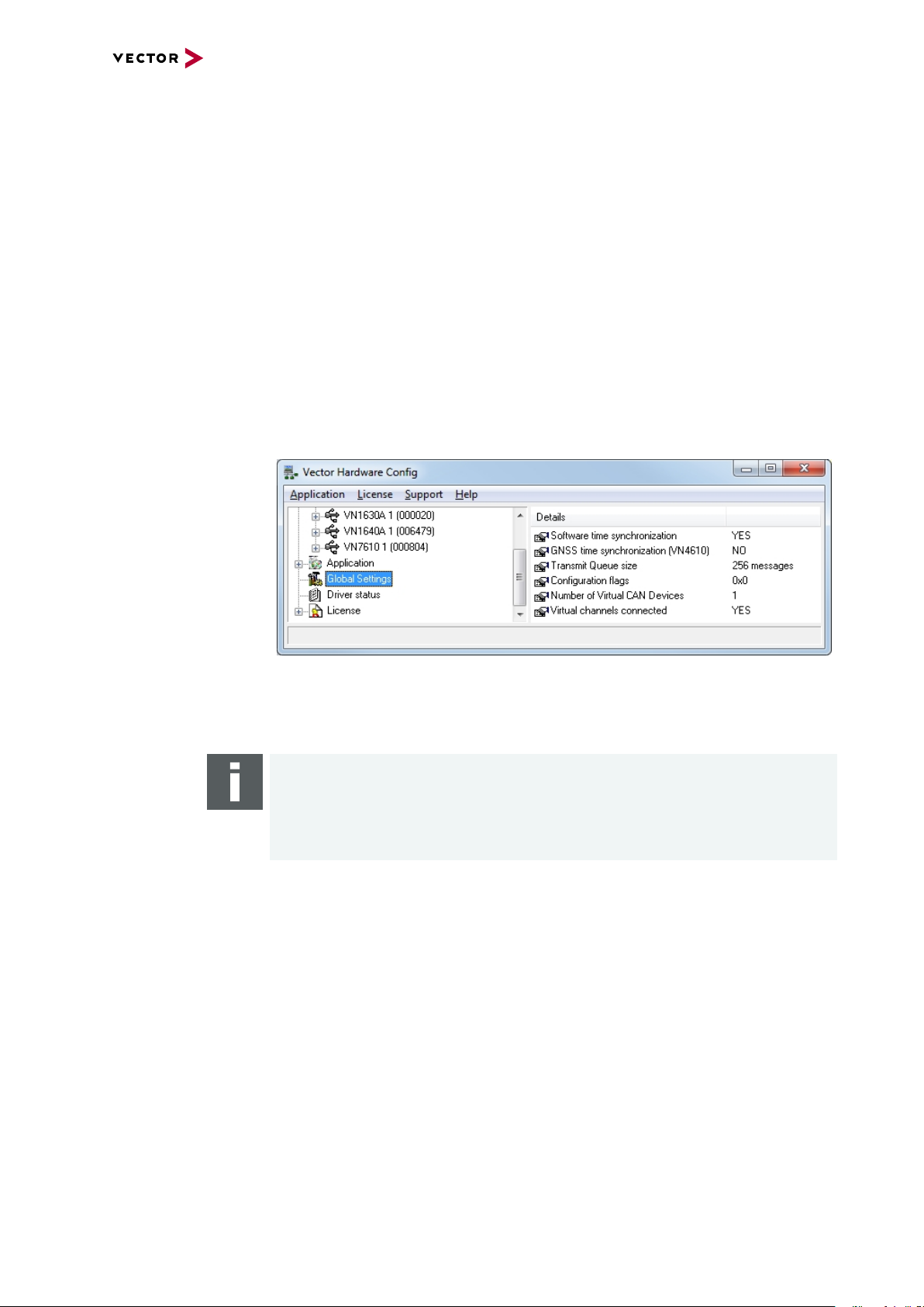
► For backwards compatibility, use software synchronization Legacy for all
devices.
► For devices with driver versions < 11.2, activate Global Settings | Software
time synchronization in Vector Hardware Config tool.
7 Time Synchronization
Figure 37: Global settings
Alternatively, disable all synchronization mechanisms and use application hardware
synchronization.
Note
The hardware synchronization must be supported by the application. For further
information please refer to the relevant application manual. Please note that the
software synchronization must be disabled, if application hardware synchronization is used.
VN4610 Manual Version 1.3 52
Page 53

7 Time Synchronization
7.9 Troubleshooting
Problem Possible Reason Solution
Vector Hardware Configuration does
not show the context menu to configure timesync on the device.
Error messages:
IEEE1588 sync not supported
(only with ETH connection)
Software sync not supported
(only with USB connection).
Old driver. Update device driver to
most recent driver.
► IEEE1588 Synchronization is only
available if the used Host Interface
is Ethernet.
► A device which uses USB con-
nection for Host Interface cannot
be configured for IEEE1588 synchronization (although the Ethernet
cable is connected physically in
addition to the USB cable).
► Software synchronization is only
available if the host interface used
is USB or PCIe.
► Disconnect the USB
cable from the device.
► Connect the Ethernet
Host cable to the
device.
► Power cycle the
device.
► Use another syn-
chronization protocol if
you want to keep the
USB Host connection.
► Disconnect the Eth-
ernet Host cable from
the device.
Synchronization cannot be established.
Red icon in Vector Hardware Configuration Tool (Status: Out of sync).
► A device that uses an Ethernet
port for the host interface cannot
be configured for software synchronization (although the Ethernet
cable is physically connected in
addition to the USB cable).
► Sync cluster not properly con-
figured.
► Slave configured but no Master
available.
► Hw Sync cable not properly con-
nected.
► No GNSS satellite signal available
(check GNSS LED).
► Used Ethernet Switch for
IEEE1588 introduces too much jitter.
► Connect the USB cable
to the device.
► Power cycle the
device.
► Use another syn-
chronization protocol if
you want to keep the
Ethernet Host connection.
VN4610 Manual Version 1.3 53
Page 54

8 Ethernet Host Connections
8 Ethernet Host Connections
In this chapter you find the following information:
8.1 General Hints 55
8.2 Getting Started 56
8.2.1 Connecting the Device 56
8.2.2 Changing the IP Address 58
8.3 Windows Network Throttling 60
8.3.1 Issue 60
8.3.2 Solution 60
8.4 Jumbo Frames 61
8.4.1 Issue 61
8.4.2 Solution 61
8.5 Interrupt Moderation Rate 62
8.5.1 Issue 62
8.5.2 Solution 62
8.6 Known Issues with 3rd Party Hardware 63
8.6.1 Intel I218 / I219 Network Cards 63
VN4610 Manual Version 1.3 54
Page 55

8 Ethernet Host Connections
8.1 General Hints
Network switches It is best to avoid network switches between your Vector network interface and your
PC. Best throughput and performance can be achieved by directly connecting your
Vector network interface to your PC.
VN4610 Manual Version 1.3 55
Page 56

8.2 Getting Started
8.2.1 Connecting the Device
Step by Step Procedure
If you want to connect your device to the PC via Ethernet, the device and the PC
have to be configured first.
1. In Windows, first check your TCP/IPv4 settings.
8 Ethernet Host Connections
Note
► Default subnet of device:
The devices are initially configured to the subnet 192.168.0.0\24.
The default IP address of the devices is 192.168.0.5
► Firewall settings:
The firewall may block the communication. The firewall requires exceptions
for the following ports:
- UDP 42600 (used by Scan network in Vector Hardware Config)
- TCP 4200, 4201 (necessary for establishing a connection to device)
VN4610 Manual Version 1.3 56
Page 57

8 Ethernet Host Connections
2. Connect the device to your PC via Ethernet. Ensure that no USB cable is connected.
3. Open Vector Hardware Config.
4. Click on Network Devices.
5. Click [Scan network]. The Ethernet device interface will be listed.
VN4610 Manual Version 1.3 57
Page 58
6. Click [Connect]. Now, the Ethernet interface is available via your network.
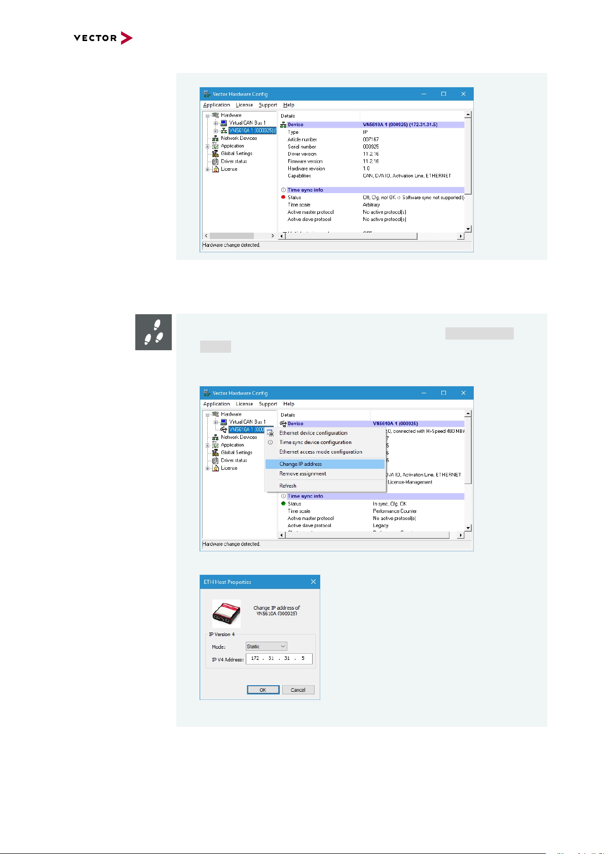
8.2.2 Changing the IP Address
Step by Step Procedure
1. Connect the device to your PC via Ethernet (see section Connecting the
Device on page 56) or via USB.
8 Ethernet Host Connections
2. In Vector Hardware Config, select an installed Ethernet interface with a right-
click and select Change IP address in the context menu.
3. Enter a suitable IP address according to your network settings and click [OK].
VN4610 Manual Version 1.3 58
Page 59

8 Ethernet Host Connections
Please follow the extra steps below if your device is connected via USB:
4. Remove the USB cable from your host and the device. Otherwise, the USB
connection is always preferred to the Ethernet connection.
5. Connect your host and the device via an Ethernet cable. The device will be listed as not available (red icon).
6. Connect the power supply to your device.
VN4610 Manual Version 1.3 59
Page 60

8.3 Windows Network Throttling
8.3.1 Issue
8 Ethernet Host Connections
Throttled network
traffic
8.3.2 Solution
Disabling
Network Throttling
Index
Ethernet network traffic is throttled on Windows PC when running a multimedia application like Windows Media Player or an internet browser. This results in increased
latency and less data throughput for Vector network interfaces, connected to the PC
via Ethernet.
In Windows operating systems, a network throttling mechanism has been existing
since 2007 which is activated as soon as the Multimedia Class Scheduler Service is
active.
In order to reduce CPU utilization by the network driver, the Network Driver Interface
Specification (NDIS) framework passes along a maximum number of packets per milliseconds. This number of packets is defined by the following registry key:
HKEY_LOCAL_MACHINE\SOFTWARE\
Microsoft\Windows NT\CurrentVersion\Multimedia\
SystemProfile\NetworkThrottlingIndex
Step by Step Procedure
Follow the steps below to disable the Network Throttling Index:
1. Open Registry Editor and navigate to the key SystemProfile.
2. Change the Value NetworkThrottlingIndex to 0xffffffff.
3. Reboot your PC.
VN4610 Manual Version 1.3 60
Page 61

8.4 Jumbo Frames
8.4.1 Issue
8 Ethernet Host Connections
Jumbo Frames not
supported
8.4.2 Solution
Activating
Jumbo Frames
For Vector network interfaces connected to a PC via Ethernet, Jumbo Frames must
be supported to achieve maximum data throughput.
Jumbo Frames allow larger Ethernet frame sizes compared to standard Ethernet
frames. Thus more user data can be transferred with a single Jumbo Frame. The data
throughput is improved by a smaller proportion of header data relative to the entire
packet.
If the data throughput should be maximized, activate Jumbo Frames. This is achieved
by directly connecting the Vector network interface to the PC or by using the correct
network switches.
Step by Step Procedure
Follow the steps below to enable Jumbo Frames:
1. Open Device Manager.
2. In the tree view, open node Network Adapters.
3. Select the NIC that is connected to the Vector network interface with a rightlick and select Properties.
4. Select tab Advanced.
5. Select the property Jumbo Packet and choose the highest possible option.
VN4610 Manual Version 1.3 61
Page 62

8 Ethernet Host Connections
8.5 Interrupt Moderation Rate
8.5.1 Issue
Increased latency Some network interface cards (NIC) have a property called Interrupt Moderation Rate
(IMR). If this property is enabled, the latency is increased while the data throughput is
improved.
8.5.2 Solution
Disabling IMR If latency should be low, disable Interrupt Moderation Rate.
Step by Step Procedure
Follow the steps below to enable Jumbo Frames:
1. Open Device Manager.
2. In the tree view, open node Network Adapters.
3. Select the NIC that is connected to the Vector network interface with a rightlick and select Properties.
4. Select tab Advanced.
5. Select the property Interrupt Moderation Rate and choose Disable.
Note
Depending on the network interface, this option may no be available.
VN4610 Manual Version 1.3 62
Page 63

8 Ethernet Host Connections
8.6 Known Issues with 3rd Party Hardware
8.6.1 Intel I218 / I219 Network Cards
Issue Intel I218 and I219 network cards have issues with jumbo frames.
Solution Disable Jumbo Frames.
VN4610 Manual Version 1.3 63
Page 64

vector.com
Visit our websitefor:
► News
► Products
► Demo software
► Support
► Trainingclasses
► Addresses
 Loading...