

Page 1
VN1500Interface Family
Manual
Version 1.3|English
Page 2

Imprint
Vector InformatikGmbH
Ingersheimer Straße 24
D-70499 Stuttgart
The information and data given in this user manual can be changed without prior notice. No part of this manual may be reproduced in any
form or by any means without the written permission of the publisher, regardless of which method or which instruments, electronic or
mechanical, are used. Alltechnicalinformation, drafts, etc. are liableto law of copyright protection.
© Copyright 2019, Vector Informatik GmbH. All rights reserved.
Page 3

Contents
Contents
1 Introduction 5
1.1 About this User Manual 6
1.1.1 Warranty 7
1.1.2 Registered Trademarks 7
1.2 Important Notes 8
1.2.1 Safety Instructions and Hazard Warnings 8
1.2.1.1 Proper Use and Intended Purpose 8
1.2.1.2 Hazards 9
1.2.1.3 Disclaimer 9
2 VN1500 Interface Family 10
2.1 Introduction 11
2.2 Accessories 11
2.3 VN1530 12
2.3.1 Main Features 12
2.3.2 Bus Configuration 13
2.3.3 Connectors Bus Side 14
2.3.4 LED 15
2.3.5 Device Preparation 16
2.3.5.1 Replacing Piggybacks 16
2.3.5.2 Device Installation 17
2.3.6 Technical Data 18
2.4 VN1531 19
2.4.1 Main Features 19
2.4.2 Onboard LIN Channels 20
2.4.3 Bus Configuration 21
2.4.4 Connectors Bus Side 22
2.4.5 LED 23
2.4.6 Device Preparation 24
2.4.6.1 Replacing Piggybacks 24
2.4.6.2 Device Installation 25
2.4.7 Technical Data 26
3 Getting Started 27
3.1 Driver Installation 28
3.2 Device Configuration 30
3.3 Loop Tests 31
3.3.1 CAN 31
VN1500 Interface Family Version 1.3 3
Page 4

Contents
4 Vector Hardware Configuration 33
4.1 General Information 34
4.2 Tool Description 35
4.2.1 Introduction 35
4.2.2 Tree View 36
5 Time Synchronization 39
5.1 General Information 40
5.2 Software Sync 42
5.3 Hardware Sync 43
VN1500 Interface Family Version 1.3 4
Page 5

1 Introduction
1 Introduction
In this chapter you find the following information:
1.1 About this User Manual 6
1.1.1 Warranty 7
1.1.2 Registered Trademarks 7
1.2 Important Notes 8
1.2.1 Safety Instructions and Hazard Warnings 8
VN1500 Interface Family Version 1.3 5
Page 6
1 Introduction
1.1 About this User Manual
Conventions In the two following charts you will find the conventions used in the user manual
regarding utilized spellings and symbols.
Style Utilization
bold Blocks, surface elements, window- and dialog names of the soft-
ware. Accentuation of warnings and advices.
[OK]
File|Save
Source Code
Hyperlink Hyperlinks and references.
<CTRL>+<S> Notation for shortcuts.
Symbol Utilization
File name and source code.
This symbol calls your attention to warnings.
Push buttons in brackets
Notation for menus and menu entries
Here you can obtain supplemental information.
Here you can find additional information.
Here is an example that has been prepared for you.
Step-by-step instructions provide assistance at these points.
Instructions on editing files are found at these points.
This symbol warns you not to edit the specified file.
VN1500 Interface Family Version 1.3 6
Page 7

1.1.1 Warranty
1 Introduction
Restriction
of warranty
We reserve the right to change the contents of the documentation and the software
without notice. Vector Informatik GmbH assumes no liability for correct contents or
damages which are resulted from the usage of the documentation. We are grateful for
references to mistakes or for suggestions for improvement to be able to offer you
even more efficient products in the future.
1.1.2 Registered Trademarks
Registered
trademarks
All trademarks mentioned in this documentation and if necessary third party
registered are absolutely subject to the conditions of each valid label right and the
rights of particular registered proprietor. All trademarks, trade names or company
names are or can be trademarks or registered trademarks of their particular proprietors. All rights which are not expressly allowed are reserved. If an explicit label of
trademarks, which are used in this documentation, fails, should not mean that a name
is free of third party rights.
► Windows, Windows 7, Windows 8.1, Windows 10
are trademarks of the Microsoft Corporation.
VN1500 Interface Family Version 1.3 7
Page 8

1.2 Important Notes
1.2.1 Safety Instructions and Hazard Warnings
Caution!
In order to avoid personal injuries and damage to property, you have to read and
understand the following safety instructions and hazard warnings prior to installation and use of this interface. Keep this documentation (manual) always near the
interface.
1.2.1.1 Proper Use and Intended Purpose
Caution!
The interface is designed for analyzing, controlling and otherwise influencing control systems and electronic control units. This includes, inter alia, bus systems like
CAN, LIN, K-Line, MOST, FlexRay, Ethernet, BroadR-Reach and/or ARINC 429.
1 Introduction
The interface may only be operated in a closed state. In particular, printed circuits
must not be visible. The interface may only be operated (i) according to the instructions and descriptions of this manual; (ii) with the electric power supply designed
for the interface, e.g. USB-powered power supply; and (iii) with accessories manufactured or approved by Vector.
The interface is exclusively designed for use by skilled personnel as its operation
may result in serious personal injuries and damage to property. Therefore, only
those persons may operate the interface who (i) have understood the possible
effects of the actions which may be caused by the interface; (ii) are specifically
trained in the handling with the interface, bus systems and the system intended to
be influenced; and (iii) have sufficient experience in using the interface safely.
The knowledge necessary for the operation of the interface can be acquired in
work-shops and internal or external seminars offered by Vector. Additional and
interface specific information, such as „Known Issues“, are available in the „Vector
KnowledgeBase“on Vector´s website at www.vector.com. Please consult the
„Vector KnowledgeBase“for updated information prior to the operation of the interface.
VN1500 Interface Family Version 1.3 8
Page 9

1.2.1.2 Hazards
1.2.1.3 Disclaimer
1 Introduction
Caution!
The interface may control and/or otherwise influence the behavior of control systems and electronic control units. Serious hazards for life, body and property may
arise, in particular, without limitation, by interventions in safety relevant systems
(e.g. by deactivating or otherwise manipulating the engine management, steering,
airbag and/or braking system) and/or if the interface is operated in public areas
(e.g. public traffic, airspace). Therefore, you must always ensure that the interface
is used in a safe manner. This includes, inter alia, the ability to put the system in
which the interface is used into a safe state at any time (e.g. by „emergency shutdown“), in particular, without limitation, in the event of errors or hazards.
Comply with all safety standards and public regulations which are relevant for the
operation of the system. Before you operate the system in public areas, it should
be tested on a site which is not accessible to the public and specifically prepared
for performing test drives in order to reduce hazards.
Caution!
Claims based on defects and liability claims against Vector are excluded to the
extent damages or errors are caused by improper use of the interface or use not
according to its intended purpose. The same applies to damages or errors arising
from insufficient training or lack of experience of personnel using the interface.
VN1500 Interface Family Version 1.3 9
Page 10

2 VN1500 Interface Family
2 VN1500 Interface Family
In this chapter you find the following information:
2.1 Introduction 11
2.2 Accessories 11
2.3 VN1530 12
2.4 VN1531 19
VN1500 Interface Family Version 1.3 10
Page 11
2.1 Introduction
2 VN1500 Interface Family
General
information
The devices of the VN1500 family offer a future-proof and powerful solution for development, simulation, test, measurement or calibration of CAN, LIN, K-Line, J1708 and
SENT networks via FPGA-based communication controllers. With this, new features
can be added in the field via software and FPGA updates.
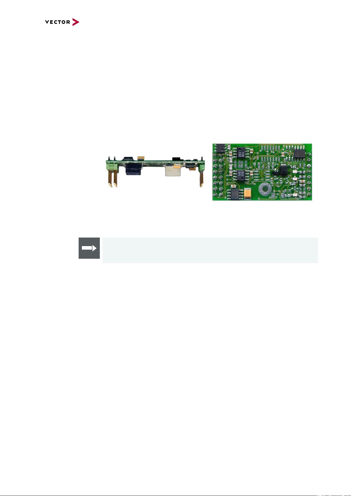
Depending on the VN1500 interface, built-in transceivers as well as exchangeable
CAN/LIN, J1708 and SENT transceivers can be used. The exchangeable transceivers are available as plug-in boards (Piggybacks) and are inserted in the VN1500.
A list of compatible Piggybacks can be found in the accessories manual on the Vector
Driver Disk.
Figure 1: Piggyback
2.2 Accessories
Reference
Information on available accessories can be found in the separate accessories
manual on the Vector Driver Disk in \Documentation\Accessories.
VN1500 Interface Family Version 1.3 11
Page 12
2.3 VN1530
2.3.1 Main Features
VN1530 features The main features of the VN1530 interface are:
► 4x onboard CAN (FD) channel
► 2x channel for CAN (FD), LIN, K-Line, J1708 and SENT,
configurable via Piggybacks
► Optimized PCIe architecture providing
- Very high receive and transmit performance
- Low latency
- Low host CPU load
► Operating temperature range: -40°C...+65°C
► Synchronization of multiple devices and other bus systems like CAN (FD), LIN,
FlexRay, MOST, Ethernet
- Software time synchronization
- Hardware time synchronization
2 VN1500 Interface Family
► Support of CAN Transport Protocol (TP) acceleration
► Support of up to sixteen VN1530 devices in one PC
- Device identification LED
► Licensor: provides Vector licenses
► Support of customer applications via the free XL-Driver Library (XL-API)
Figure 2: VN1530 CAN/LIN Interface
VN1500 Interface Family Version 1.3 12
Page 13
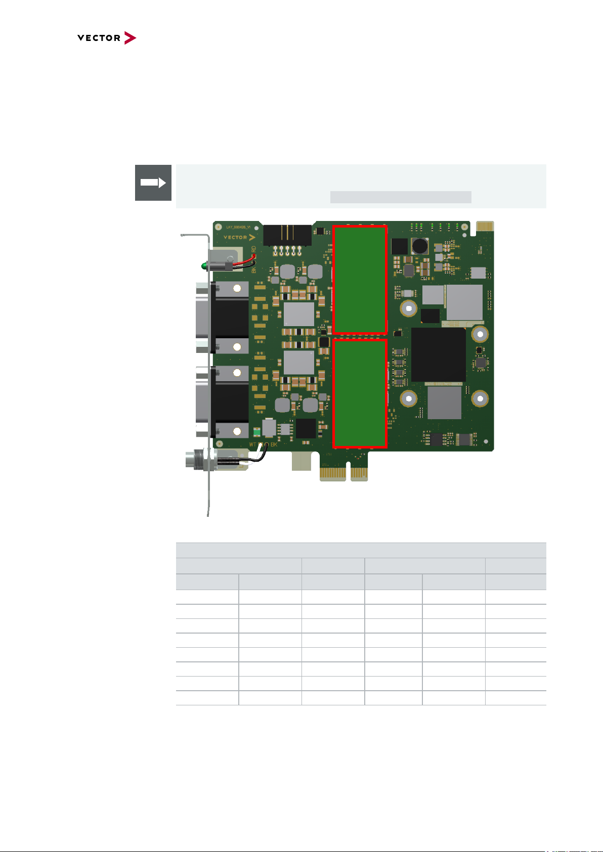
2.3.2 Bus Configuration
CH3
Piggyback 1
CH6
Piggyback 2
2 VN1500 Interface Family
Piggybacks for
CH3 and CH6
The VN1530 offers two Piggyback plug-in locations (CH3/CH6). Depending on
requirements, electrically decoupled CAN FD, CAN High-Speed, CAN Low-Speed,
LIN, J1708 or SENT transceivers may be used. In addition, four electrically decoupled
onboard CAN 1057G transceivers are available (CH1/CH2 and CH4/CH5).
Reference
A list of compatible Piggybacks can be found in the accessories manual on the
Vector Driver Disk or on the web: https://kb.vector.com/entry/219/.
Figure 3: Piggyback plug-in locations
Onboard Piggyback Onboard Piggyback
CH1 CH2 CH3 CH4 CH5 CH6
CAN CAN CAN CAN CAN CAN
CAN CAN CAN CAN CAN SENT
CAN CAN CAN CAN CAN LIN/K-Line
CAN CAN SENT CAN CAN LIN/K-Line
CAN CAN LIN CAN CAN LIN/K-Line
CAN CAN CAN CAN CAN CAN CAN SENT CAN CAN CAN CAN - CAN CAN LIN
J1708 should be handled like CAN.
Channel Configurations
VN1500 Interface Family Version 1.3 13
Page 14
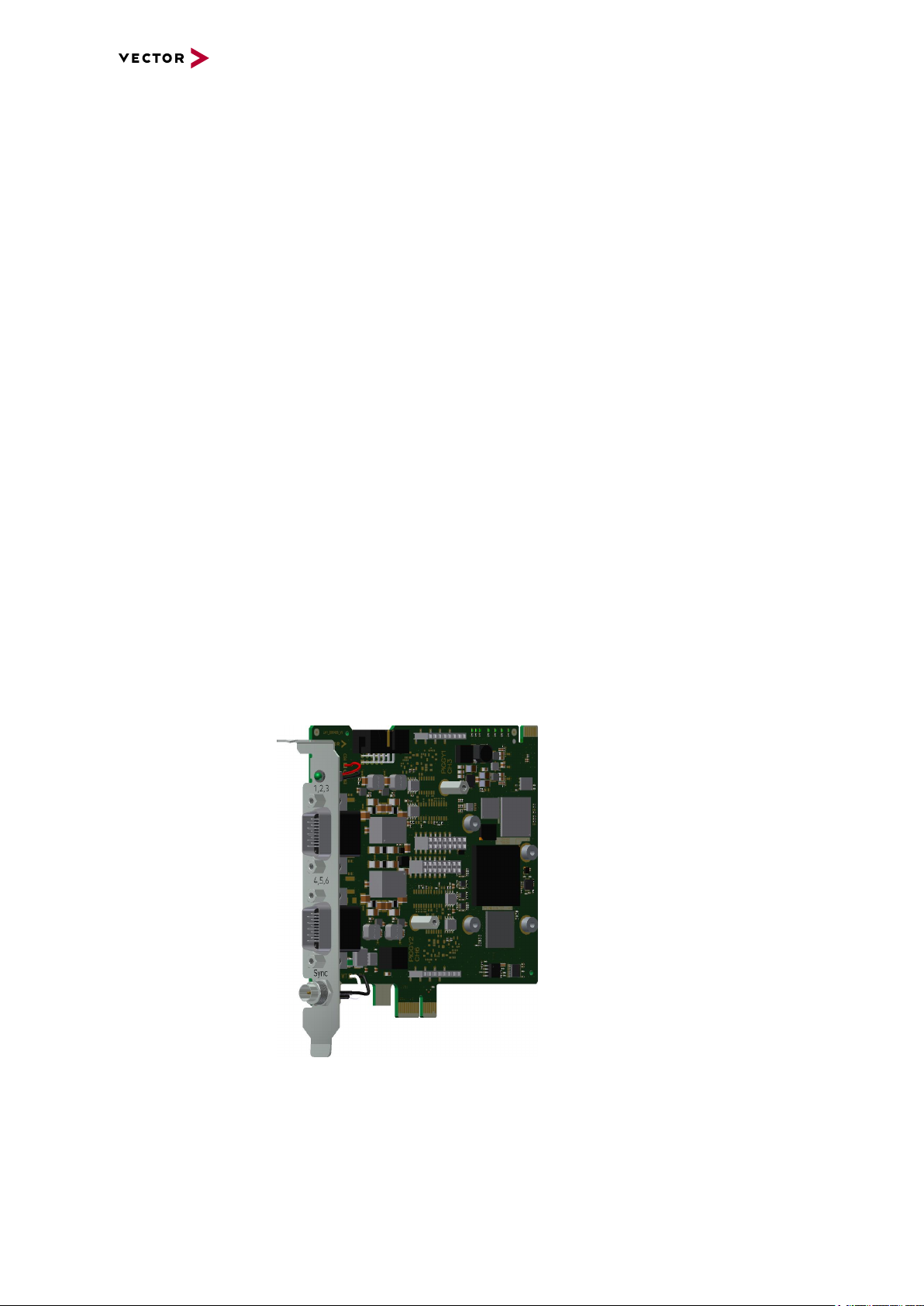
2.3.3 Connectors Bus Side
3
1
2
Device connectors
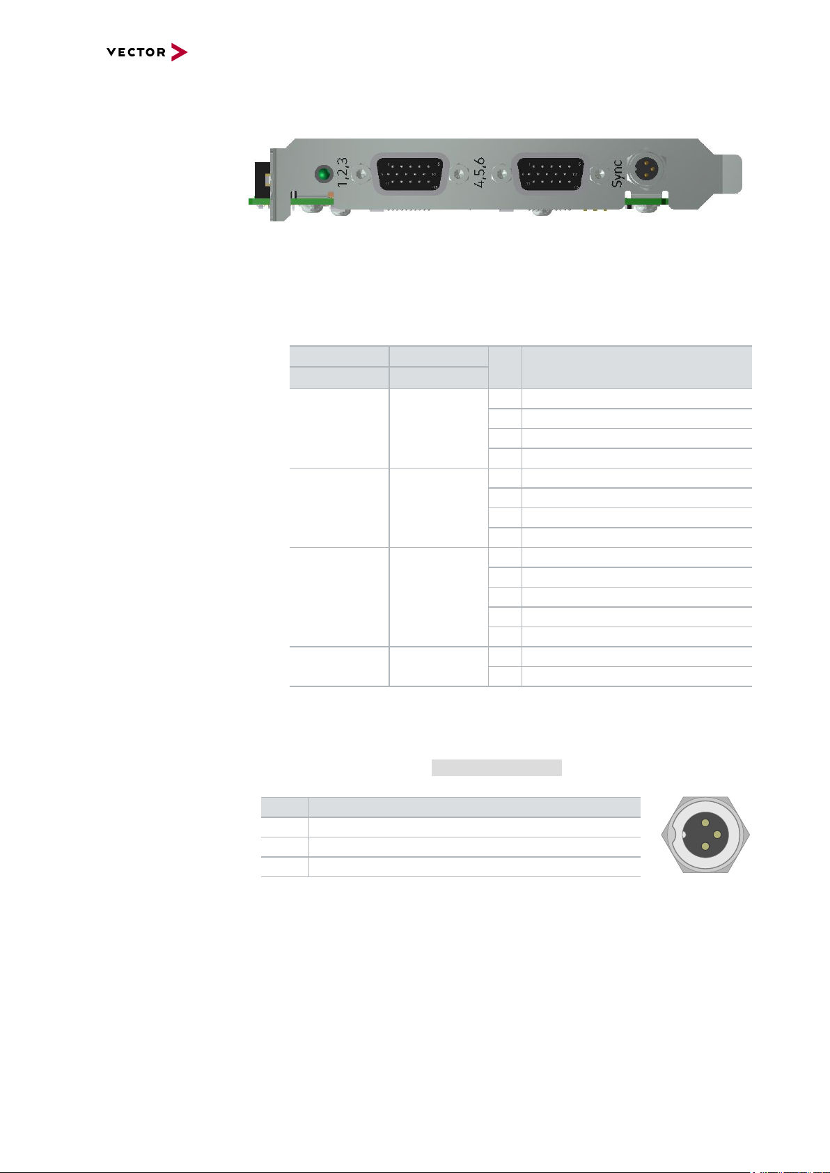
Figure 4: VN1530 with D-SUB15 connectors and sync
► 2x D-SUB15 (CH1...CH6)
The VN1530 has two D-SUB15HD connectors. Each connector provides two
onboardCAN/CAN FD channels as well as an optional channel via a CAN, LIN,
J1708 or SENT Piggyback. The pin assignment is as follows:
2 VN1500 Interface Family
Connector 1 Connector 2
Channel Channel
Pin Assignment
5 Vcc
1 4
10 GND
14 CAN Low
15 CAN High
3 CAN Low
2 5
4 CAN High
9 GND
13 Vcc
1 CAN Low /J1708 B*
6 CAN High/ LIN / J1708 A / SENT*
3 6
7 GND*
8 Vcc*
11 Special function / Pdis*
- -
* via CAN, LIN, J1708 or SENT Piggyback
2 Not connected
12 Not connected
► Binder connector (Sync)
This connector (Binder type 711) can be used for time synchronization of different
Vector devices (see section Time Synchronization on page 39). The sync con-
nector is not intended to connect a power supply.
Pin Assignment
1 Not connected
2 Synchronization line
3 Ground
VN1500 Interface Family Version 1.3 14
Page 15

13579
246810
2.3.4 LED
2 VN1500 Interface Family
► 10-pin connector (internal hardware sync)
The angled 10 pin onboard sync connector can be used for time synchronization of
different PCIe devices, e.g. VN1530, VN1531 or VN7572. For synchronization, a
ribbon cable with a 10-pin standard connector is required.
Pin Assignment
1 GND
2...8 Reserved. Do not connect.
9 Synchronization line (low active)
10 Internal sync supply (output 5 V, 35 mA)
Note
Forwarding a synchronization pulse from the external to the internal sync connector and vice versa is not possible. The only simultaneous usage of the internal
and external connector is if the device acts as a synchronization master which generates sync pulses.
Description The VN1530 has a LED that can be used for device identification when using multiple
VN1500 devices. The LED can be twinkled via Vector Hardware Config.
VN1500 Interface Family Version 1.3 15
Page 16

2.3.5 Device Preparation
CH3
Piggyback 1
CH6
Piggyback 2
2 VN1500 Interface Family
General
information
With the onboard transceivers, the device can be operated without additional Piggybacks. If you want to extend the channels for specific bus types (see section Bus Configuration on page 13), one or more Piggybacks have to be inserted before the device
installation.
Reference
Please find a list of compatible Piggybacks in section "Transceiver Compatibility"
of the accessories manual on the Vector Driver Disk in
\Documentation\Accessories.
2.3.5.1 Replacing Piggybacks
Caution!
Please follow these instructions if no Piggyback is inserted or if another Piggyback
needs to be inserted. When performing this operation be sure not to touch the top or
bottom of the boards (VN1530 main board or Piggybacks) to avoid damages due to
electrical discharges.
Step by Step Procedure
1. Detach the screw with the screw protection and remove the Piggyback carefully.
Figure 5: Piggyback plug-in locations
VN1500 Interface Family Version 1.3 16
Page 17

2. Insert the replacement Piggyback. The connectors must fit and must not be displaced laterally.
3. The Piggyback has to be fixed again with the screw and the screw protection.
2.3.5.2 Device Installation
Caution!
Turn off the main power supply and disconnect your computer’s power cord. Otherwise systems using an ATX power supply unit with soft power off may still be
powering the PCIe slot. This can damage your PCIe card when it is inserted into
the slot.
Caution!
Do not force the VN1530 into the slot. Make sure that the connectors of the card’s
PCIe connector are aligned with the bus connector on the motherboard before you
insert the card into the slot. If it does not fit properly, gently remove it and try again.
2 VN1500 Interface Family
Note
Please observe all safety precautions prescribed by your PC manufacturer for card
installation!
Step by Step Procedure
1. Install the drivers as described in section Driver Installation on page 28.
2. Turn off the computer and all peripheral devices.
3. Unplug the power cord from the wall outlet.
4. Touch a metal plate on your computer to ground yourself to discharge any static
electricity.
5. Remove the computer cover and the metal brackets from an unused slot.
6. Align the VN1530 with the PCIe slot and press it gently but firmly into the slot.
7. Replace the computer cover.
8. Plug in the power cord.
9. Turn on the computer.
VN1500 Interface Family Version 1.3 17
Page 18

2.3.6 Technical Data
CAN channels 4x CAN/CANFD onboard
LIN channels Max. 2 (configurable via Piggybacks),
K-Line channels Max. 1 at channel 6
J1708 channels Max. 2 at channel 3/6
SENT channels Max. 1 at channel 3/6
Time stamps Resolution: 8 ns
Power consumption 4.5 W
Temperature range
(ambient temperature of VN1530)
Relative humidity of ambient air 15 %...95 %, non-condensing
Dimensions (LxWxH) Approx. 132 mm x 127 mm x 22 mm
Weight Approx. 105g (without Piggybacks)
Operating system requirements Windows 7 SP1 (32 bit / 64 bit)
2 VN1500 Interface Family
- NXP TJA1057G
- electrically decoupled
2x configurable via CANpiggies
CAN: up to 2 Mbit/s
CAN FD: up to 8 Mbit/s
Up to 300 kbit/s, depending on the bus physics
(with LINpiggy 7269mag)
(configurable via Piggybacks)
(with SENSORpiggy SENT)
Accuracy (within one device): 1 µs
Accuracy software sync: typ. 10 µs
Accuracy hardware sync: typ. 1 µs
Operating: -40 °C...+65 °C
Shipping and storage: -40 °C...+85 °C
(with mounted Piggybacks)
Windows 8.1 (32 bit / 64 bit)
Windows 10 (64 bit)
VN1500 Interface Family Version 1.3 18
Page 19

2.4 VN1531
2.4.1 Main Features
VN1531 features The main features of the VN1531 interface are:
► 4x onboard LIN channel
- Stress functionality, supports disturbance of the LIN bus by dominant or
recessive disturbing bits
- Flash mode support
► 2x channel for CAN (FD), LIN, K-Line, J1708 and SENT,
configurable via Piggybacks
► Optimized PCIe architecture providing
- Very high receive and transmit performance
- Low latency
- Low host CPU load
2 VN1500 Interface Family
► Operating temperature range: -40°C...+65°C
► Synchronization of multiple devices and other bus systems like CAN (FD), LIN,
FlexRay, MOST, Ethernet
- Software time synchronization
- Hardware time synchronization
► Support of CAN Transport Protocol (TP) acceleration
► Support of up to sixteen VN1531 devices in one PC
- Device identification LED
► Licensor: provides Vector licenses
► Support of customer applications via the free XL-Driver Library (XL-API)
Figure 6: VN1531 LIN/CAN Interface
VN1500 Interface Family Version 1.3 19
Page 20

2.4.2 Onboard LIN Channels
2 VN1500 Interface Family
Bus-side
voltage supply
Properties The onboard LINchannels are designed for usage in 12V passenger car and 24V
Minimal baudrate Due to the dominant timeout (6…20 ms) of the transceiver, it may not be possible to
Stress functionality The stress functionality of the onboard LINchannels enable the disturbance of the LIN
The onboard LIN channels provide an internal supply voltage. Since the recessive
level on the bus depends on the supply voltage of the master, it is advisable to operate
the onboard LIN channel with an external supply voltage that is also used by the other
bus nodes. This prevents cross currents between the individual nodes on the LIN bus.
An externally applied supply voltage is used by the onboard LIN channels if it has a
higher level than the 12V internal supply voltage; if the external supply voltage has a
smaller level than the internal supply voltage, the internal supply voltage is used.
To force the onboard LIN channels to use the external supply voltage even if it has a
lower level than the internal supply voltage, the pin Pdis has to be connected to the
GND pin of the same channel.
truck LIN networks. They provide a time limitation to prevent constant dominant level
on the LIN bus (dominant timeout of the transceiver). The minimum switch off time of
the onboard LINchannels is 6 ms.
transmit a LIN header at very low baudrates. Therefore intended dominant sequences
longer than 6 ms are created using the onboard channel's integrated transistor circuitry.
bus by dominant or recessive disturbing bits. The disturbing bits can be any length.
Note
The recessive disturbing unit is protected by a 550mA fuse, the dominant disturbing unit by a 100mA fuse.
In case of dominant disturbing bits, the onboard LINchannels have a protection
against thermal overloads. The onboard LINchannels must be externally supplied
to use recessive disturbing mode.
Flash mode The flash mode enables higher data transmission rates which can be used for pro-
gramming microcontrollers e.g. during ECU production. This is possible by an
increased slew rate of the transceiver, which may also affect EMC properties.
VN1500 Interface Family Version 1.3 20
Page 21

2.4.3 Bus Configuration
CH3
Piggyback 1
CH6
Piggyback 2
2 VN1500 Interface Family
Piggybacks for
CH3 and CH6
The VN1531 offers two Piggyback plug-in locations (CH3/CH6). Depending on
requirements, electrically decoupled CAN FD, CAN High-Speed, CAN Low-Speed,
LIN, J1708 or SENT transceivers may be used. In addition, four electrically decoupled
onboard LIN 7269 transceivers are available (CH1/CH2 and CH4/CH5).
Reference
A list of compatible Piggybacks can be found in the accessories manual on the
Vector Driver Disk or on the web: https://kb.vector.com/entry/219/.
Figure 7: Piggyback plug-in locations
Onboard Piggyback Onboard Piggyback
CH1 CH2 CH3 CH4 CH5 CH6
LIN LIN LIN LIN LIN/K-Line LIN
LIN LIN LIN LIN LIN/K-Line CAN
LIN LIN LIN LIN LIN/K-Line SENT
LIN LIN CAN LIN LIN/K-Line CAN
LIN LIN CAN LIN LIN/K-Line SENT
LIN LIN LIN LIN LIN/K-Line LIN LIN - LIN LIN/K-Line CAN
LIN LIN - LIN LIN/K-Line SENT
J1708 should be handled like CAN.
Channel Configurations
VN1500 Interface Family Version 1.3 21
Page 22

2.4.4 Connectors Bus Side
3
1
2
Device connectors
Figure 8: VN1531 with D-SUB15 connectors and sync
► 2x D-SUB15 (CH1...CH6)
The VN1531 has two D-SUB15HD connectors. Each connector provides two
onboardLIN channels as well as an optional channel via a CAN, LIN, J1708 or
SENT Piggyback. The pin assignment is as follows:
2 VN1500 Interface Family
Connector 1 Connector 2
Channel Channel
Pin Assignment
5 Vcc
1 4
10 GND
14 Pdis
15 LIN
3 Pdis
2 5
4 LIN
9 GND
13 Vcc
1 CAN Low /J1708 B*
6 CAN High/ LIN / J1708 A / SENT*
3 6
7 GND*
8 Vcc*
11 Special function / Pdis*
- -
* via CAN, LIN, J1708 or SENT Piggyback
2 Not connected
12 Not connected
Caution!
Please note when using the LIN signal Pdis via VNcable 3Y:
While Pdis of the Piggyback channel is available on the corresponding D-SUB9
connector at pin 4, Pdis of the onboard channel is available on the corresponding
D-SUB9 connector at pin 2.
► Binder connector (Sync)
This connector (Binder type 711) can be used for time synchronization of different
Vector devices (see section Time Synchronization on page 39). The sync con-
nector is not intended to connect a power supply.
Pin Assignment
1 Not connected
2 Synchronization line
3 Ground
VN1500 Interface Family Version 1.3 22
Page 23

13579
246810
2.4.5 LED
2 VN1500 Interface Family
► 10-pin connector (internal hardware sync)
The angled 10 pin onboard sync connector can be used for time synchronization of
different PCIe devices, e.g. VN1530, VN1531 or VN7572. For synchronization, a
ribbon cable with a 10-pin standard connector is required.
Pin Assignment
1 GND
2...8 Reserved. Do not connect.
9 Synchronization line (low active)
10 Internal sync supply (output 5 V, 35 mA)
Note
Forwarding a synchronization pulse from the external to the internal sync connector and vice versa is not possible. The only simultaneous usage of the internal
and external connector is if the device acts as a synchronization master which generates sync pulses.
Description The VN1531 has a LED that can be used for device identification when using multiple
VN1500 devices. The LED can be twinkled via Vector Hardware Config.
VN1500 Interface Family Version 1.3 23
Page 24

2.4.6 Device Preparation
CH3
Piggyback 1
CH6
Piggyback 2
2 VN1500 Interface Family
General
information
With the onboard transceivers, the device can be operated without additional Piggybacks. If you want to extend the channels for specific bus types (see section Bus Configuration on page 21), one or more Piggybacks have to be inserted before the device
installation.
Reference
Please find a list of compatible Piggybacks in section "Transceiver Compatibility"
of the accessories manual on the Vector Driver Disk in
\Documentation\Accessories.
2.4.6.1 Replacing Piggybacks
Caution!
Please follow these instructions if no Piggyback is inserted or if another Piggyback
needs to be inserted. When performing this operation be sure not to touch the top or
bottom of the boards (VN1531 main board or Piggybacks) to avoid damages due to
electrical discharges.
Step by Step Procedure
1. Detach the screw with the screw protection and remove the Piggyback carefully.
Figure 9: Piggyback plug-in locations
VN1500 Interface Family Version 1.3 24
Page 25

2. Insert the replacement Piggyback. The connectors must fit and must not be displaced laterally.
3. The Piggyback has to be fixed again with the screw and the screw protection.
2.4.6.2 Device Installation
Caution!
Turn off the main power supply and disconnect your computer’s power cord. Otherwise systems using an ATX power supply unit with soft power off may still be
powering the PCIe slot. This can damage your PCIe card when it is inserted into
the slot.
Caution!
Do not force the VN1531 into the slot. Make sure that the connectors of the card’s
PCIe connector are aligned with the bus connector on the motherboard before you
insert the card into the slot. If it does not fit properly, gently remove it and try again.
2 VN1500 Interface Family
Note
Please observe all safety precautions prescribed by your PC manufacturer for card
installation!
Step by Step Procedure
1. Install the drivers as described in section Driver Installation on page 28.
2. Turn off the computer and all peripheral devices.
3. Unplug the power cord from the wall outlet.
4. Touch a metal plate on your computer to ground yourself to discharge any static
electricity.
5. Remove the computer cover and the metal brackets from an unused slot.
6. Align the VN1531 with the PCIe slot and press it gently but firmly into the slot.
7. Replace the computer cover.
8. Plug in the power cord.
9. Turn on the computer.
VN1500 Interface Family Version 1.3 25
Page 26

2.4.7 Technical Data
LIN channels - Piggyback channels:
2 VN1500 Interface Family
- 2x configurable via LINpiggies
- for technical specification please refer
to the corresponding manual
- Onboard channels:
- 4x LIN
- support of LIN V2.1
- transceiver: TLE7269
- electrically decoupled
- Operation modes:
- Normal mode: 20 kbit/s
- Flash mode, depending on the bus
physics:
- up to 300 kBit/s at 12 V
- up to 115.2 kBit/s at 24 V
- External supply voltage:
- normal operation (incl. recessive dis-
turbing mode): 8V ... 36V
- extended range: 0V ... 36V
- Bus termination:
- Master mode: 1kOhm
- Slave mode: typ. 30kOhm
CAN channels Max. 2 (configurable via Piggybacks)
CAN: up to 2 Mbit/s
CAN FD: up to 8 Mbit/s
K-Line channels Max. 1 at channel 5
(with onboard LIN transceiver TLE7269)
J1708 channels Max. 2 at channel 3/6
(configurable via Piggybacks)
SENT channels Max. 1 at channel 6
(with SENSORpiggy SENT)
Time stamps Resolution: 8 ns
Accuracy (within one device): 1 µs
Accuracy software sync: typ. 10 µs
Accuracy hardware sync: typ. 1 µs
Power consumption 4.5 W
Temperature range
(ambient temperature of VN1531)
Relative humidity of ambient air 15 %...95 %, non-condensing
Dimensions (LxWxH) Approx. 132 mm x 127 mm x 22 mm
Weight Approx. 108g (without Piggybacks)
Operating system requirements Windows 7 SP1 (32 bit / 64 bit)
Operating: -40 °C...+65 °C
Shipping and storage: -40 °C...+85 °C
(with mounted Piggybacks)
Windows 8.1 (32 bit / 64 bit)
Windows 10 (64 bit)
VN1500 Interface Family Version 1.3 26
Page 27

3 Getting Started
3 Getting Started
In this chapter you find the following information:
3.1 Driver Installation 28
3.2 Device Configuration 30
3.3 Loop Tests 31
3.3.1 CAN 31
VN1500 Interface Family Version 1.3 27
Page 28

3.1 Driver Installation
3 Getting Started
General
information
The Vector Driver Disk offers a driver setup which allows the installation or the
removal of Vector devices.
Note
Please note that you will need Administrator Rights for the following steps.
Step by Step Procedure
1. Execute the driver setup from the autostart menu or directly from
\Drivers\Setup.exe before the card is inserted into the PC.
If you have already inserted the card, the Windows found new Hardware wiz-
ard appears. Close this wizard and then execute the driver setup.
2. Click [Next] in the driver setup dialog. The initialization process starts.
VN1500 Interface Family Version 1.3 28
Page 29

3 Getting Started
3. In the driver selection dialog, select your devices to be installed (or to be uninstalled).
4. Click [Install] to execute the driver installation, or [Uninstall] to remove exist-
ing drivers.
5. A confirmation dialog appears. Click [Close] to exit. After successful installation, the card is ready for operation and can be inserted into the PC.
Note:Please find further details on PCI/PXI or PCIe card installation in this
manual.
VN1500 Interface Family Version 1.3 29
Page 30

3 Getting Started
3.2 Device Configuration
Configuration Before the installed device can be used in an application, it must be properly con-
figured for the needed use case. This configuration is done with the Vector Hardware
Config tool which comes with the driver installation. The tool can be found in Win-
dows | Start | Settings | Control Panel | Vector Hardware and manages all
installed Vector devices.
Reference
Further details on Vector Hardware Config can be found in the installation instruc-
tions (see section Vector Hardware Configuration on page 33).
VN1500 Interface Family Version 1.3 30
Page 31

3 Getting Started
3.3 Loop Tests
Operation test The test described here can be performed to check the functional integrity of the driver
and the device. This test is identical for Windows 7 / Windows 8.1 / Windows 10 and
independent of the used application.
3.3.1 CAN
Device test The operating test for CAN requires either two high-speed or two low-speed trans-
ceivers and can be executed as follows:
Step by Step Procedure
1. Connect two CAN channels with a suitable cable.
If two high-speed transceivers are being used, we recommend our
CANcable1 (CANcable0 for low-speed transceivers).
2. Start \Drivers\Common\Loop3.exe from the Vector Driver Disk.
This program accesses the Vector devices and transmits CAN messages.
3. Select the connected CAN channels of the device(s) to be tested.
VN1500 Interface Family Version 1.3 31
Page 32

3 Getting Started
4. Set the appropriate baudrate depending on the transceiver being used (highspeed max. 1,000,000 Bd, low-speed max. 125,000 Bd).
5. Click [Start].
6. You will see statistical data in the lower part of the window if the system has
been configured properly.
7. The test procedure can be terminated with the [Stop] button.
An OK should appear in the upper part of the window.
VN1500 Interface Family Version 1.3 32
Page 33

4 Vector Hardware Configuration
4 Vector Hardware Configuration
In this chapter you find the following information:
4.1 General Information 34
4.2 Tool Description 35
4.2.1 Introduction 35
4.2.2 Tree View 36
VN1500 Interface Family Version 1.3 33
Page 34

4.1 General Information
4 Vector Hardware Configuration
Executing Vector
Hardware Config
Control Panel
Windows 7
Control Panel
Windows 8.1
After the successful driver installation you will find the configuration application
Vector Hardware in the Control Panel (see below). The tool gives you information
about the connected and installed Vector devices. There are also several settings that
can be changed.
Figure 10: Icon in Control Panel
► Category view
Windows Start | Control Panel | Hardware and Sound,
click Vector Hardware in the list.
► Symbols view
Windows Start | Control Panel,
click Vector Hardware in the list.
► Category view
<Windows key>+<X> | Control Panel | Hardware and Sound,
click Vector Hardware in the list.
► Symbols view
<Windows key>+<X> | Control Panel,
click Vector Hardware in the list.
Control Panel
Windows 10
► Category view
<Windows key>+<X> | Control Panel | Hardware and Sound,
click Vector Hardware in the list.
► Symbols view
<Windows key>+<X> | Control Panel,
click Vector Hardware in the list.
VN1500 Interface Family Version 1.3 34
Page 35

4.2 Tool Description
physical CH1
CAN
physical CH2
LIN
Vector Device 1
Vector Device 2
physical CH1
FlexRay
physical CH2
CAN
not assigned
l
ogical channel
CAN 1
Application
l
ogical channel
LIN 1
l
ogical channel
CAN 1
l
ogical channel
FlexRay 1
l
ogical channel
CAN 2
4.2.1 Introduction
Vector
Hardware Config
Figure 11: General view of Vector Hardware Config
4 Vector Hardware Configuration
Logical and physical
channels
Vector Hardware Config enables the channel configuration between installed Vector
devices and applications. Applications use so-called logical channels which are hardware independent and have to be assigned to real hardware channels.
Figure 12: Concept of channel assignments
VN1500 Interface Family Version 1.3 35
Figure 13: Channel assignment in Vector Hardware Config
Page 36

4.2.2 Tree View
4 Vector Hardware Configuration
Accessing
Vector devices
The tool is split into two windows. The left window has a tree view and lets you
access the installed Vector devices, the right window displays the details of the selection. The following nodes are available in the tree view:
Hardware The Hardware section lists the installed Vector devices. Each device item has phys-
ical channels which can be assigned to any number of logical channels (e.g.
CANalyzer CAN 1). A logical channel can be assigned to only one physical channel.
Figure 14: Hardware
Application In Application, all available applications are displayed in a tree view. According to
each application, the assignments of logical and physical channels are displayed in
the right part of the window. If no assignment exists, the information Not assigned
appears. The assignment can be edited via a right-click.
Figure 15: Application
VN1500 Interface Family Version 1.3 36
Page 37

4 Vector Hardware Configuration
Global settings Global settings contains global device configuration possibilities, e.g. software time
synchronization, GNSS time synchronization, transmit queue size, configuration
flags or the number of virtual CAN devices.
Figure 16: Global settings
Driver status Driver status offers an overall status information of devices and applications cur-
rently in use. You can see whether the channels are connected to the bus (online/offline) and whether the time synchronization is activated or not (Time-Sync-On/TimeSync-Off).
Figure 17: Dr iver status
VN1500 Interface Family Version 1.3 37
Page 38

4 Vector Hardware Configuration
License The License section contains information on all current available licenses (Vector bus
devices, Vector License USB dongle devices).
Figure 18: License
Reference
You will find a detailed description of Vector Hardware Config in the online help
(Help | Contents).
VN1500 Interface Family Version 1.3 38
Page 39

5 Time Synchronization
5 Time Synchronization
In this chapter you find the following information:
5.1 General Information 40
5.2 Software Sync 42
5.3 Hardware Sync 43
VN1500 Interface Family Version 1.3 39
Page 40

5.1 General Information
CAN
Vector
CAN Interface
CH1
CH2
Time Stamp Clock
PC
CANalyzer/CANoe
USB
5 Time Synchronization
Time stamps
and events
Generating
time stamps
Time stamps are useful when analyzing incoming or outgoing data or event
sequences on a specific bus.
Figure 19: Time stamps of two CAN channels in CANalyzer
Each event which is sent or received by a Vector network interface has an accurate
time stamp. Time stamps are generated for each channel in the Vector network interface. The base for these time stamps is a common hardware clock in the device.
Figure 20: Common time stamp clockfor each channel
If the measurement setup requires more than one Vector network interface, a synchronization of all connected interfaces and their hardware clocks is needed.
Due to manufacturing and temperature tolerances, the hardware clocks may vary in
speed, so time stamps of various Vector devices drift over time.
VN1500 Interface Family Version 1.3 40
Page 41

5 Time Synchronization
CAN
FlexRay
Vector
CAN Interface
CH1
CH2
Time Stamp Clock
PC
Vector
FR Interface
CHA
CHB
Time Stamp Clock
sec
0.000000
0.100376
0.200382
0.300372
0.400406
0.500593
0.600242
sec
0.000000
0.1003
83
0.200
982
0.30
1456
0.40
2612
0.50
3885
0.60
4092
CANalyzer/CANoe
USB
USB
Figure 21: Example of unsynchronized network interfaces. Independent time stamps drift apar t
To compensate for these time stamp deviations between the Vector network interfaces, the time stamps can be either synchronized by software or by hardware (see
next section).
Note
The accuracy of the software and hardware sync depends on the interface. Further
information on specific values can be found in the technical data of the respective
devices.
VN1500 Interface Family Version 1.3 41
Page 42

5.2 Software Sync
CAN
FlexRay
Vector
CAN Interface
CH1
CH2
Time Stamp Clock
Vector
FR Interface
CHA
CHB
Time Stamp Clock
synchronization
by software (PC clock)
sec
0.000000
1.100
356
1.200
362
2.300
362
2.400
356
3.500
353
3.600
362
PC
sec
0.000000
1.100
413
1.200
421
2.300
429
2.400
419
3.500
415
3.600
420
PC clock
CANalyzer/CANoe
USB
USB
5 Time Synchronization
Synchronization
by software
The software time synchronization is driver-based and available for all applications
without any restrictions. The time stamp deviations from different Vector network interfaces are calculated and synchronized to the common PC clock. For this purpose no
further hardware setup is required.
Figure 22: Time stamps of devices are synchronized to the PC clock
The setting of the software time synchronization can be changed in the Vector Hard-
ware Config tool in General information | Settings | Software time synchronization.
Figure 23: Switching on the software synchronization
► YES
The software time synchronization is active.
► NO
The software time synchronization is not active. Use this setting only if the Vector
network interfaces are being synchronized over the sync line or if only a single
device is used.
VN1500 Interface Family Version 1.3 42
Page 43

5.3 Hardware Sync
VN1630A
VN5610A
VN1640A
Multi
SYNCbox
external
VN1640A
USB PC
PC
VN7570
SYNCcable XL
SYNCcable XL
SYNCcable XL
SYNCcable XL
USB PC
Vector Devices
USB PC
USB PC
USB PC
Power
VN5610A
VN8912A
Power
VN5610A
VN1640A
Multi
SYNCbox
external
VN1640A
USB VN8912A
USB PC
SYNCcable XL
SYNCcable XL
SYNCcable XL
SYNCcable XL
Power
Power
5 Time Synchronization
Synchronization
by hardware
A more accurate time synchronization of multiple devices is provided by the hardware
synchronization which has to be supported by the application (e.g. CANalyzer,
CANoe). Two Vector network interfaces can therefore be connected with the
SYNCcableXL (see accessories manual, part number 05018).
In order to synchronize up to five devices at the same time, a distribution box is available (see accessories manual, part number 05085).
Figure 24: Example of a time synchronization with multiple devices
Figure 25: Example of a time synchronization with VN8912A and additional devices
At each falling edge on the sync line which is initiated by the application, the Vector
network interface generates a time stamp that is provided to the application. This
VN1500 Interface Family Version 1.3 43
Page 44

5 Time Synchronization
CANalyzer/CANoe
CAN
FlexRay
Vector
CAN Interface
CH2
Time Stamp Clock
USB
Vector
FR Interface
CHB
Master Time Stamp Clock
synchronization
by hardware (SYNCcable)
sec
0.000000
1.10037
5
1.20038
1
2.30037
1
2.40040
5
3.50059
2
3.60024
1
CH1
CHA
sec
0.000000
1.100376
1.200382
2.300372
2.400406
3.500593
3.600242
PC
USB
allows the application to calculate the deviations between the network interfaces and
to synchronize the time stamps to a common time base (master clock) which is
defined by the application.
Figure 26: Time stamps are synchronized to the master clock
Note
The hardware synchronization must be supported by the application. For further
information please refer to the relevant application manual. Please note that the
software synchronization must be disabled (see Vector Hardware Config | Gen-
eral information | Settings | Software time synchronization) if the hardware
synchronization is used.
VN1500 Interface Family Version 1.3 44
Page 45

Get More Information
Visit our website for:
► News
► Products
► Demo software
► Support
► Training classes
► Addresses
www.vector.com
 Loading...