

Page 1
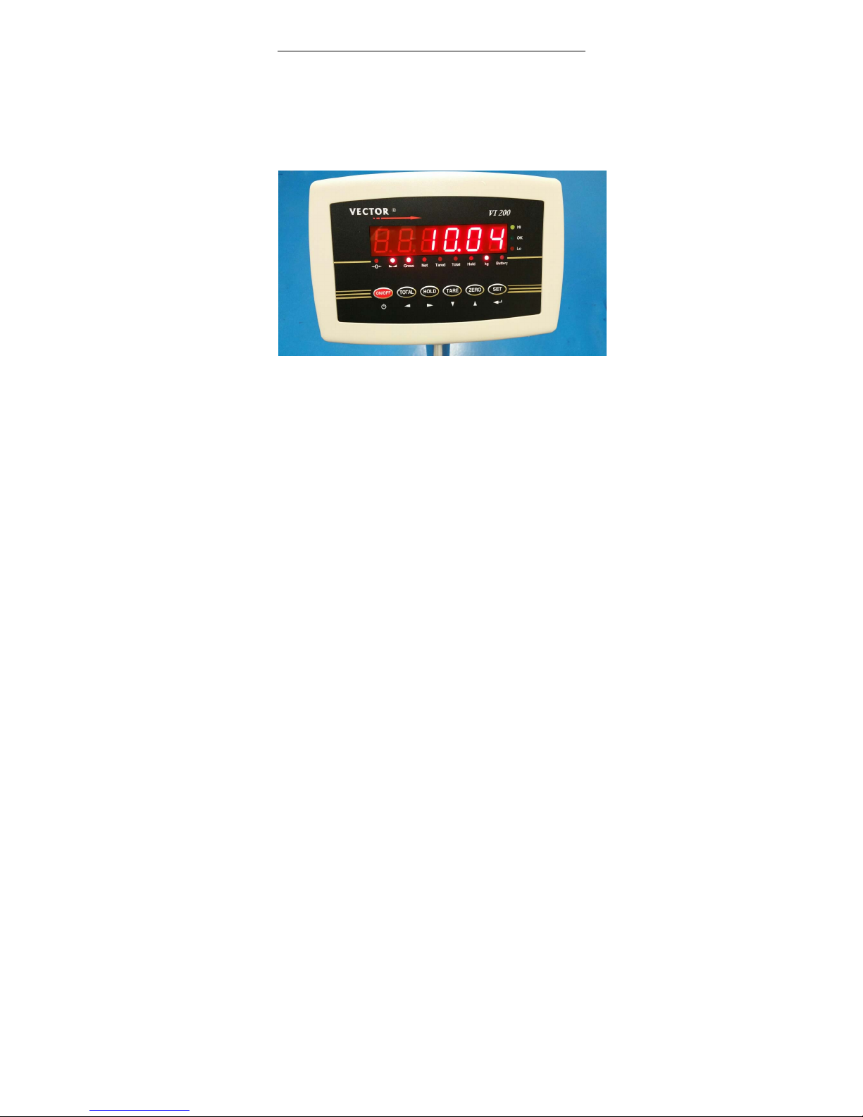
Weighing Indicator
User manual
Page 2
User Manual
Page 1 of 27
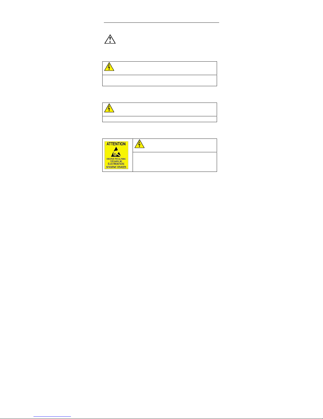
safety instruction
For safety operation pls. follow the safety instruction.
WA RN I NG
set. Calibrate, inspect and fix the the weighing indicator is prohibited by Non
professional staff
WA RN I NG
Pls. make sure the weighing display well earthing
WA RN I NG
The indicator is electrostatic sensitive device, pls. power off
during electrical connections, internal components touched by
hand is prohibited, and please take the anti-static measure
Page 3

User Manual
Page 2 of 27
LIST
1. Summary ..................................................................................................... 3
1.1 Main function .................................................................................... 3
1.2 Technical parameter .......................................................................... 3
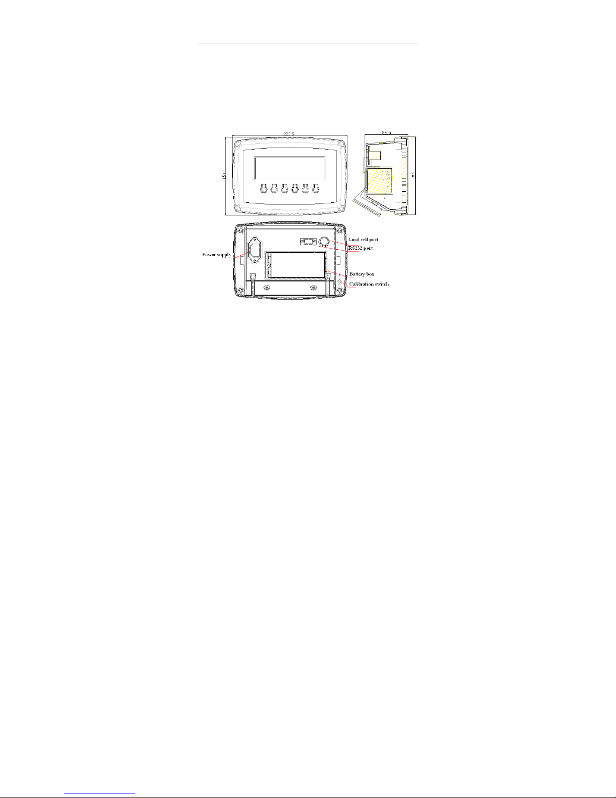
1.3 Outline and installation picture ......................................................... 4
1.4 Battery ............................................................................................... 5
2. Installation and Calibration ......................................................................... 5
2.1 connection indicator with load cell ................................................... 5
2.2 communication interface ................................................................... 6
3. Basic operation ............................................................................................ 6
3.1 Key and display ................................................................................. 6
3.2 Power on .......................................................................................... 10
3.3 Zero setting ...................................................................................... 10
3.4 TARE ............................................................................................... 10
3.5 HOLD .............................................................................................. 10
3.6 TOTAL ............................................................................................ 11
3.7 10 times high resolutions .............................................................. 12
3.8 Up and Low limit alarm .................................................................. 12
3.9 Print function ................................................................................... 13
4 Calibration & parameter setting ................................................................. 13
4.1 Enter calibration .............................................................................. 13
4.2. Step of calibration operation: ......................................................... 14
4.3 Application parameter setting .......................................................... 16
4.4 Communication setting ................................................................... 17
4.5 Application setting .......................................................................... 18
4.6 Exit setting ...................................................................................... 20
5.Output data format ..................................................................................... 20
5.1 Computer continuous sending format ............................................. 20
5.2 Big display continuous sending format ........................................... 21
5.3 Serial interface reception command: ............................................ 22
5.4 Print output format .......................................................................... 23
5.5 Print the accumulated output format ............................................... 23
6. Maintenance .............................................................................................. 24
6.1 Regular Error and maintain method ................................................ 24
6.2 Daily maintenance ........................................................................... 25
6.3 Restore default parameters .............................................................. 26
Page 4

User Manual
Page 3 of 27
1. Summary
1.1Mainfunction
》General weighing: zero tare
》Animal weighing: Peak-hold. Data-hold, Auto-hold
》Accumulation
》Optional by RS232
》Low battery remind
》Power off automatically
1.2Technicalparameter
》Stimulating voltage:+3.3 VDC
》A/D converting speed: 10 SPS
》Load signal range: 0~12.8mV
》load capacity: it can connect 4 pcs 350
Ω load cell at most
》weight unit: kg.
》
Resolution: 3000e
》Interval: 1/2/5/10/20/50
》Display: 6-digits LED/LCD,word height: 20.3mm
》key: ON/OFF TOTAL HOLD TARE ZERO SET
》Interface:RS232C Baud rate optional 1200/2400/4800/9600
Page 5
User Manual
Page 4 of 27
》Operation temperature: -10~40℃
》
Storage temperature: -20~+60℃
》optional power: 4V/4Ah rechargeable battery
110/220VAC
1.3Outlineandinstallationpicture
Page 6

User Manual
Page 5 of 27
1.4Battery
1. when you use the internal battery first time,you should charge the battery
10-12 hours, to prevent low voltage resulted from self leakage of battery.
2. when the red battery light is on and flashes,it means low battery You
should charge battery in time.
3. Charge time: 10-12 hours And it works 45 hours
4. When the battery light turns green, it means fully charged
5. If you don’t use the battery long time, take out the battery to protect the
indicator from battery leakage
6. In order to keep the battery in best using condition, it is suggest that you
fully discharge the battery every month, the method is that using the
indicator till it is automatically power off.
2. Installation and Calibration
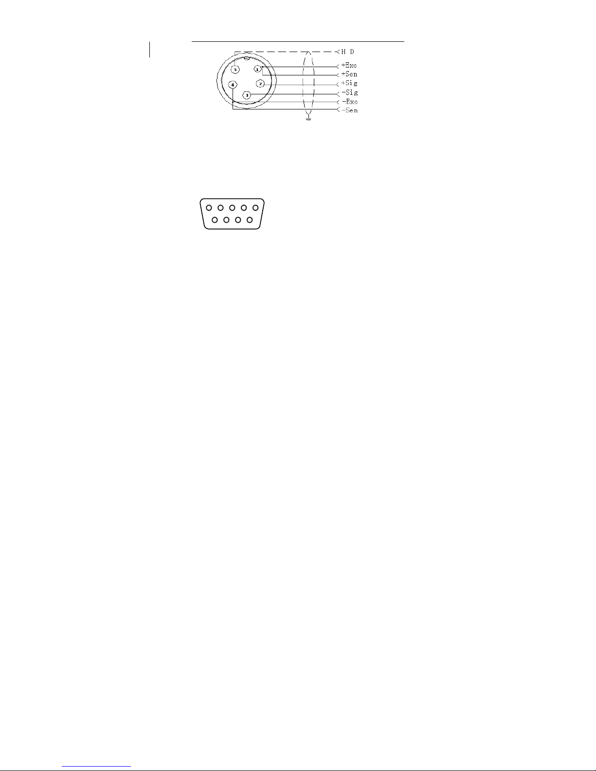
2.1connectionindicatorwithloa d cell
it can connect four pcs 350Ωload cell at most, both four and six line load
cell are ok. To make it simple, we use quick connector
Or standard plug. As belows
Page 7
User Manual
Page 6 of 27
Quick connector connection
2.2communicationinterface
PIN2-------TXD
5 4 3 2 1 PIN3------RXD
PIN5 --------GND
9 8 7 6
3. Basic operation
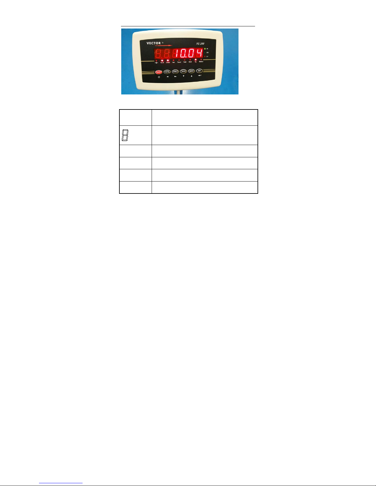
3.1Keyanddisplay
Page 8
User Manual
Page 7 of 27
Weighing indicator display instruction
LED display instruction
Weighing data display
Kg Weight unit kg
HOLD Hold the data
Tare Display tare status
Net Display net weight
Page 9
User Manual
Page 8 of 27
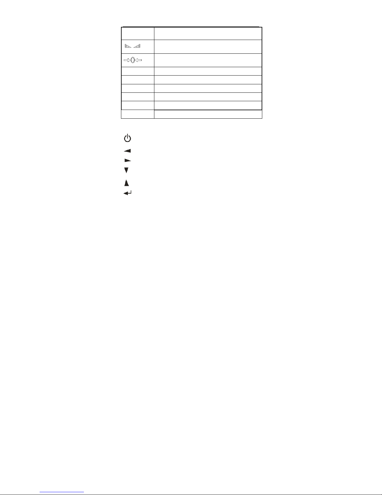
Gross Display gross weight
Display data keep still
zero, indicating zero weight
Battery Using battery
Hi Over Limit
OK Within Limit
Lo Below Limit
Total Accumulation
Count Counting function
Key’s function
ON/OFF, EXIT AND SAVE SETTING
LEFT
RIGHT
DOWN
UP
CONFIRM, GO TO NEXT STEP
Page 10

User Manual
Page 9 of 27
Key symbol Key name Key function
SET
Work together with “on/off” enter and exit
calibration
ZERO
Clear weight within zero range
TAR E
1.At Gross mode, tare the loaded weight
2.At Net mode, display gross weight after
deduct tare
HOLD
Enter and exit “hold” mold
TOTAL accumulating operation
ON/OFF
Press it for 2 seconds to power on or power
off
Page 11

User Manual
Page 10 of 27
3.2Poweron
Power on and indicator perform self-checking and go to weighing mode.
3.3Zerosetting
Within zero range, press “zero”, indicator weighing is cleared. When
Indicator is not stable, zero is unworkable.
3.4TAR E
At the gross weight mode, if the weight is stable, pls. press ”Tare” key , the
indicator will take the loaded weight as tare, and show net weight,
At this time the gross mode will change to net mode. The “ net” and “tare”
light is on, and the net weight is zero
3.5HOLD
C11=0 “hold” function unworkable
C11=1 PEAK HOLD
Press” HOLD” key, the Hold light is on, and show the Maximum data on the
Page 12

User Manual
Page 11 of 27
weighing indicator. Press “ HOLD” key again to exit the hold function
C11=2 Data-hold
Press” HOLD” key, the Hold light is on, and show the data on the weighing
indicator. Press “ HOLD” key again to exit the hold function
C11=3 Auto-hold
If the weight on the scales above 20d and keep stable, the indicator will show
the data for 6 seconds and the “ hold” light Is on , after 6 seconds the
indicator back to general weighing, and the “ hold” light is off
C11=4 Special Animal weighing function
Press” Hold” key, the indicator will show” LOC” for 3 seconds, the “ hold”
light is on, During the 3 seconds, the indicator will catch the average weight
and show it.
Press” HOLD” key again to exit it
3.6TOT AL
Accumulation operation
At Zero mode, load weight till stable, Press “TOTAL” key go to
accumulating
Mode,” total” light on, display” n001”, and then display loaded weight;
unload weight , back to zero, load weight again till stable. Press ”TOTAL”,
display”n002”
Then show the loaded weight. Repeat it maximum 999 times.
Page 13

User Manual
Page 12 of 27
Check the total weight operation:
Press “SET” hold it then press “TOTAL” At the same time, display ”n**”,
(accumulating times) then display total weight.
There are 8 data totally. It shows the first 4 digital. then the last 4 digital
For example, the first 4 digital is”0012”, the last 4 digital is”34,56”
It means the actual weight is “1234.56”
At TOTAL (accumulate) mode, Press “TOTAL” key the indicator
show“ clrn”, it means don’t clear the total Weight, Press “
key
confirm it and exit ; if clear total weight, Press “ ” “ ”
“clrn” change to “clry” it means clear total weight display. Press “
”to
clear the the total weight and exit accumulating mode.
3.710timeshighresolutions
Press “ SET” and “TARE” key at the same time, you will get 10 times high
resolutions. And it back to normal weighing after 3 seconds.
3.8UpandLowlimitalarm
Pls. set C13= Up limit, C14=Low Limit, when the weight is over up limit,
the “HI” light will on, and indicator will make a sound to alarm.; when the
Page 14

User Manual
Page 13 of 27
weight is below than the low limit, the “LO” light will on.. when the weight
is within the limit, the “OK” light is ok.
3.9Printfunction
When the data is stable, connection with printer, it will be printed after
press“
”1 second.
Note:print the gross weight when at tare mode , if the net weight is zero.
Can not print.
4 Calibration & parameter
setting
4.1Entercalibration
There have two methods to enter the setting menu:
1. when the switch” CAL” is off, Press”
” then press” at the
same time, hold it, you will enter C08-C39 setting.
2. Take out the sealing screw on the back of indicator, then press
Page 15

User Manual
Page 14 of 27
down the “span” Press still and then press at the same time ,
you will enter C01-C39 setting.
4.2.Stepofcalibrationoperation:
According to the second method which can enter setting menu, C01-C39
C01 UNIT
[C01 ] Press
[C1 1] unit is kg
Press
, go to next step
C02 Set decimal digits
[C02 ] Press
option:0/1/2/3/4
[C2 0] no decimal point
[C2 1] one decimal point
[C2 2] two decimal point
[C2 3] three decimal point
Press
, go to next step
C03 Division setting
Page 16

User Manual
Page 15 of 27
[C03 ] Press
[C3 1] d=1
[C3 2] d=2
[C3 5] d=5
[C3 10] d=10
[C3 20] d=20
[C3 50] d=50
Press
, go to next step
C04 Maximum capacity
For example:max weighing 100kg:
set [0100.00]
Press
, go to next step
C05 Zero calibration
option:0=non-calibration zero 1=need calibration zero
calibration zero please choose 1 and ensure scale is empty and “stable” light
is on. countdown[CAL 10]~[CAL 0], then the indicator will
show[0.00](example for two decimal point).
C06 Loading calibration
[C06], Press
, show [C06 0], press , change to [C06 1],
Press
, show [SPAn ],
Basic on max capacity setting, add suitable weight on scale. close to the max
capacity, heavier than 10% max at least.
For example: the weight is 80kg
Page 17

User Manual
Page 16 of 27
As bellows:
[0080.00]
[CAL 9]
……
[0080.00]
[CALEnd]
count down over, indicator shows loaded weight , loading calibration finish.
If you want to set application parameter. Press
If you want to exit.
Press
C07 Default parameters setting
[C07 0] non-restore default parameters
[C07 1] restore default parameters
Note: after the above parameters setting finish, please do not set default
parameters often, avoid the original setting parameters lost.
4.3Applicationparametersetting
C08 warning tone
[C8 1] open warning tone
[C8 0] close warning tone
C09 Power off automatically
[C9 0] Non-power off
[C9 10] keep still within 10 min. power off automatically
[C9 30] keep still within 30 min. power off automatically
[C9 60] keep still within 60 min. power off automatically
Page 18

User Manual
Page 17 of 27
C10 Power saving setting
[C10 0] close backlight
[C10 1] close backlight after 1 minute
[C10 2] always backlight
C11 Hold
[C11 0] No Hold function
[C11 1] Peck hold
[C11 2] Data hold
[C11 3] Auto-hold
[C11 4] Animal weighing
C12 Hold time ( if you choose C11=4, you can set the time )
[C12 3] 3 seconds
[C12 5] 5 seconds
C13 Upper limit alarm value
C14 Low limit alarm value
C15 Check inner code
4.4Communicationsetting
C18 Serial interface setting
[C18 0] No sending
[C18 1] Big display
[C18 2] Print format output
[C18 3] Command mode(Z =zero T=tare R=Reply weight
[C18 4] continuous sending
C19 BAUD RATE
[C19 0] 1200bit/s
Page 19

User Manual
Page 18 of 27
[C19 1] 2400bit/s
[C19 2] 4800bit/s
[C19 3] 9600bit/s
4.5Applicationsetting
C20 Manually Zero
[C20 00] no Manually Zero
[C20 01] Manually Zero range ±1% Max. capacity
[C20 02] Manually Zero range ±2% Max. capacity
[C20 04] Manually Zero range ±4% Max. capacity
[C20 10] Manually Zero range ±10% Max. capacity
[C20 20] Manually Zero range ±20% Max. capacity
[C20100] Manually Zero range ±100% Max. capacity
C21 Initially zero
[C21 0] No initially zero
[C21 1] Initially zero range±1% Max. capacity
[C21 2] Initially zero range±2% Max. capacity
[C21 5] Initially zero range±5% Max. capacity
[C21 10] Initially zero range±10% Max. capacity
[C21 20] Initially zero range±20% Max. capacity
C22 Zero tracking range
[C22 0.0] No zero tracking
[C22 0.5] ±0.5d
[C22 1.0] ±1.0d
[C22 2.0] ±2.0d
[C22 3.0] ±3.0d
Page 20

User Manual
Page 19 of 27
[C22 4.0] ±4.0d
[C22 5.0] ±5.0d
C23 Zero tracking time
[C23 0] No zero tracking
[C23 1] 1 second
[C23 2] 2 seconds
[C23 3] 3 seconds
C24 Overload range
[C24 09] Over 9d than max. capacity
C25 Negative display
[C25 00] Less than -9d
[C25 10] Less -10% Max. capacity
[C25 20] Less -20% Max. capacity
[C25 50] Less -50% Max. capacity
[C25100] Less -100% Max. capacity
C26 Standstill time
[C26 0] Quick
[C26 1] Medium
[C26 2] Slow
C27 Standstill range
[C27 1] ±1d
[C27 2] ±2d
[C27 5] ±5d
[C27 10] ±10d
C28 Dynamic filter
[C28 0] close dynamic filter
[C28 1] Low dynamic filter
[C28 3] Medium dynamic filter
Page 21

User Manual
Page 20 of 27
[C28 5] High dynamic filter
C29 Noisy filter
[C29 0] Close noisy filter
[C29 1] Low noisy filter
[C29 2] Medium filter
[C29 3] High filter
4.6Exitsetting
For example [C10 1], Press , confirm it then press to exit and
save it
5.Output data format
5.1Computercontinuoussendingformat
, ,
CR LF
S 1 S 2 S 3 Data
S 4
S1: weight status, ST= standstill, US= not standstill, OL= overload
Page 22

User Manual
Page 21 of 27
S2: weight mode, GS=gross mode, NT=net mode
S3: weight of positive and negative, “+” or ” –“
S4: measurement unit, “kg” or “lb”
Data: weight value, including decimal point
CR:
carriage return
LF: line feed
5.2Bigdisplaycontinuoussendingformat
Output continuous format
S
T
X
S
W
A
S
W
B
S
W C XXXXXXXX X XXX
C
R
C
K
S
1 2 3 4 5 6
State A
Bits0,1,2
0 1 2 Decimal point position
1 0 0 XXXXXX0
0 1 0 XXXXXXX
1 1 0
XXXXX.X
0 0 1
XXXX.XX
1 0 1
XXX.XXX
Bits3,4 Division
0 1 X1
1 0 X2
Page 23

User Manual
Page 22 of 27
State B
BitsS function
Bits0
gross=0, net=1
Bits1
symbol:positive =0,negative =1
Bits2
overload(or lower zero)=1
Bits3 dynamic=1
Bits4
unit:lb=0, kg=1
Bits5 Constant 1
Bits6 Constant 0
State C
Bit2 Bit1 Bit0 unit
0 0 0 Kg or lb
0 0 1 g
0 1 0 t
Bit 3 printing=1
Bit 4
Extend
display=1
Bit 5 Constant 1
Bit 6 Constant 0
5.3Serialinterfacereceptioncommand:
RS232COM serial interface can receive simple ASCII command.
Command word and role as follows:
Page 24

User Manual
Page 23 of 27
Command name role
T
Tare off command Save and clear tare
Z
Zero command Zero the gross weight
P
Print command Print the weight
R
Read gross/ net
weight
Read gross/net weight
5.4Printoutputformat
NO. 004 (NO.)
G.W: 8.88kg (gross,example for two decimal point)
T.W: 2.88kg (tare)
N.W: 6.00kg (net)
5.5Printtheaccumulatedoutputformat
NO. 004 (NO.)
Total: 003 (accumulate times,example for 3 times is 003)
Total.W: 2.88kg (accumulate weight)
Page 25

User Manual
Page 24 of 27
6. Maintenance
6.1RegularErrorandmaintainmethod
Error Reason instruction Solution
Display
UUUUUU
1. the loaded weight
excess overload range of
max. capacity
2. wrong connection
with load cell or no
connection with it.
3. load cell unworkable
1.decrease loaded weight
2. check load cell
connection
3. checking load cell:check
input and output resistance
to judge it is good or not.
Display nnnnnn
1. calibration is no good
2 、 cell single line is
connect a wrong line.
3、the cell is bad.
1. check scale is resisted or
not, foot is kept level or not.
2. check load cell
connection.
3. checking load cell:check
input and output resistance
to judge it is good or not.
ERR1
during calibration, no
input added weight or
input weight exceed
max capacity.
Input the correct weight
Page 26

User Manual
Page 25 of 27
ERR2
during calibration, the
added weights not
enough
Added weight at least
10%of Max. capacity,
Recommend the weights is
60-80% the Max. capacity
ERR3
during calibration, input
single is negative.
1..Check connection is
correct or not.
Check load cell is damaged
or not.
3. renew calibration, if still
wrong. pls replace the PCB
ERR4
During calibration,
single is unstable
Ensure added weight and
scale is stable, start
calibration
ERR5 EEPROM check error change PCB.
6.2Dailymaintenance
1. In order to ensure indicator display clearly and prolong use life, the
indicator should not be placed directly on sunlight.
2. Load cell and indicator should be well connected , the system should
have a good ground, away from strong electric field, magnetic field.
3. Do not use indicator outside in rainy, better keep it power off.
4. Power off firstly while plug and unplug
Page 27

User Manual
Page 26 of 27
6.3Restoredef a u lt parameters
Enter setting menu, set C07= 1,press then press exit saving
setting, all parameters will be back to default setting.
Note:Pls. do not restore default parameter easily if you are not professional
and have not scale calibration.
Default parameter form
parameter instruction Default value
C01
Calibration unit
1
C02
decimal digits
0
C03
Division value
1
C04
Max capacity
10000
C05
Empty scales calibration
0
C06
Capacity calibration
0
C07
restore the default parameters
0
C08
War nin g to ne
1
C09
Automatic power off
0
C10
Power saving mode
0
C11
Hold function
0
C12
Animal weighing mode
0
C13
Upper limit warning
000000
C14 Lower limit warning 000000
C15 Inner code display
Page 28

User Manual
Page 27 of 27
C16 Date
C17 Time
C18 Serial interface data output methord 0
C19 Serial interface Baud rate 3=9600
C20 Manual zero setting 2
C21 Initical zero setting 10
C22 Automatic zero tracking range 0.5
C23 Automatic zero tracking time 1
C24 Verload range 9
C25 Negative display range 10
C26 Standstill time 1
C27 Standstill range 2
C28 Dynamic filter 0
C29 Noisy filter 2
C30~C40 Reseverd menu
 Loading...