

Page 1
VH6501CAN Disturbance Interface
Manual
Version 1.0|English
Page 2

Imprint
Vector Informatik GmbH
Ingersheimer Straße 24
D-70499 Stuttgart
The information and data given in this user manual can be changed without prior notice. No part of this manual may be reproduced in any
form or by any means without the written permission of the publisher, regardless of which method or which instruments, electronic or
mechanical, are used. All technical information, drafts, etc. ar e liable to law of copyright protection.
© Copyright 2017, Vector Informatik GmbH. All rights reserved.
Page 3
Contents
Contents
1 Introduction 4
1.1 About this User Manual 5
1.1.1 Certification 6
1.1.2 Warranty 6
1.1.3 Registered Trademarks 6
1.2 Important Notes 7
1.2.1 Safety Instructions and Hazard Warnings 7
1.2.1.1 Proper Use and Intended Purpose 7
1.2.1.2 Hazards 8
1.2.1.3 Disclaimer 8
2 Device Description 9
2.1 Scope of Delivery 10
2.2 Introduction 10
2.3 Accessories 10
2.4 Connectors Bus Side 11
2.5 Connectors USB Side 14
2.6 LEDs 17
2.7 Technical Data 19
3 Getting Started 21
3.1 Driver Installation 22
3.2 Device Configuration 24
4 Vector Hardware Configuration 25
4.1 General Information 26
4.2 Tool Description 27
4.2.1 Introduction 27
4.2.2 Tree View 28
5 Time Synchronization 31
5.1 General Information 32
5.2 Software Sync 34
5.3 Hardware Sync 35
VH6501 Manual Version 1.0 3
Page 4
1 Introduction
1 Introduction
In this chapter you find the following information:
1.1 About this User Manual 5
1.1.1 Certification 6
1.1.2 Warranty 6
1.1.3 Registered Trademarks 6
1.2 Important Notes 7
1.2.1 Safety Instructions and Hazard Warnings 7
VH6501 Manual Version 1.0 4
Page 5
1 Introduction
1.1 About this User Manual
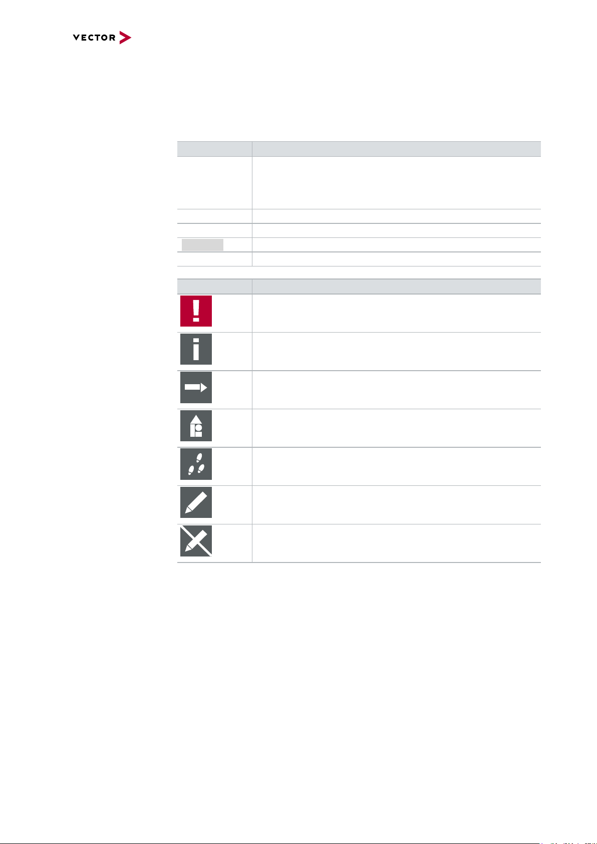
Conventions In the two following charts you will find the conventions used in the user manual
regarding utilized spellings and symbols.
Style Utilization
bold Blocks, surface elements, window- and dialog names of the soft-
ware. Accentuation of warnings and advices.
[OK]
File|Save
Microsoft Legally protected proper names and side notes.
Source Code
Hyperlink Hyperlinks and references.
<CTRL>+<S> Notation for shortcuts.
Symbol Utilization
File name and source code.
This symbol calls your attention to warnings.
Push buttons in brackets
Notation for menus and menu entries
Here you can obtain supplemental information.
Here you can find additional information.
Here is an example that has been prepared for you.
Step-by-step instructions provide assistance at these points.
Instructions on editing files are found at these points.
This symbol warns you not to edit the specified file.
VH6501 Manual Version 1.0 5
Page 6

1.1.1 Certification
1 Introduction
Certified Quality
Management System
Vector Informatik GmbH has ISO 9001:2008 certification. The ISO standard is a globally recognized standard.
1.1.2 Warranty
Restriction
of warranty
We reserve the right to change the contents of the documentation and the software
without notice. Vector Informatik GmbH assumes no liability for correct contents or
damages which are resulted from the usage of the documentation. We are grateful for
references to mistakes or for suggestions for improvement to be able to offer you
even more efficient products in the future.
1.1.3 Registered Trademarks
Registered
trademarks
All trademarks mentioned in this documentation and if necessary third party
registered are absolutely subject to the conditions of each valid label right and the
rights of particular registered proprietor. All trademarks, trade names or company
names are or can be trademarks or registered trademarks of their particular proprietors. All rights which are not expressly allowed are reserved. If an explicit label of
trademarks, which are used in this documentation, fails, should not mean that a name
is free of third party rights.
> Windows, Windows 7, Windows 8.1, Windows 10
are trademarks of the Microsoft Corporation.
VH6501 Manual Version 1.0 6
Page 7

1.2 Important Notes
1.2.1 Safety Instructions and Hazard Warnings
Caution!
In order to avoid personal injuries and damage to property, you have to read and
understand the following safety instructions and hazard warnings prior to installation
and use of this interface. Keep this documentation (manual) always near the interface.
1.2.1.1 Proper Use and Intended Purpose
Caution!
The interface is designed for analyzing, controlling and otherwise influencing control
systems and electronic control units. This includes, inter alia, bus systems like
CAN, LIN, K-Line, MOST, FlexRay, Ethernet, BroadR-Reach and/or ARINC 429.
1 Introduction
The interface may only be operated in a closed state. In particular, printed circuits
must not be visible. The interface may only be operated (i) according to the instructions and descriptions of this manual; (ii) with the electric power supply designed for
the interface, e.g. USB-powered power supply; and (iii) with accessories manufactured or approved by Vector.
The interface is exclusively designed for use by skilled personnel as its operation
may result in serious personal injuries and damage to property. Therefore, only
those persons may operate the interface who (i) have understood the possible
effects of the actions which may be caused by the interface; (ii) are specifically
trained in the handling with the interface, bus systems and the system intended to
be influenced; and (iii) have sufficient experience in using the interface safely.
The knowledge necessary for the operation of the interface can be acquired in workshops and internal or external seminars offered by Vector. Additional and interface
specific information, such as „Known Issues“, are available in the „Vector KnowledgeBase“on Vector´s website at www.vector.com. Please consult the „Vector
KnowledgeBase“for updated information prior to the operation of the interface.
VH6501 Manual Version 1.0 7
Page 8

1.2.1.2 Hazards
1.2.1.3 Disclaimer
1 Introduction
Caution!
The interface may control and/or otherwise influence the behavior of control systems and electronic control units. Serious hazards for life, body and property may
arise, in particular, without limitation, by interventions in safety relevant systems
(e.g. by deactivating or otherwise manipulating the engine management, steering,
airbag and/or braking system) and/or if the interface is operated in public areas (e.g.
public traffic, airspace). Therefore, you must always ensure that the interface is
used in a safe manner. This includes, inter alia, the ability to put the system in
which the interface is used into a safe state at any time (e.g. by „emergency shutdown“), in particular, without limitation, in the event of errors or hazards.
Comply with all safety standards and public regulations which are relevant for the
operation of the system. Before you operate the system in public areas, it should be
tested on a site which is not accessible to the public and specifically prepared for
performing test drives in order to reduce hazards.
Caution!
Claims based on defects and liability claims against Vector are excluded to the
extent damages or errors are caused by improper use of the interface or use not
according to its intended purpose. The same applies to damages or errors arising
from insufficient training or lack of experience of personnel using the interface.
VH6501 Manual Version 1.0 8
Page 9
2 Device Description
2 Device Description
In this chapter you find the following information:
2.1 Scope of Delivery 10
2.2 Introduction 10
2.3 Accessories 10
2.4 Connectors Bus Side 11
2.5 Connectors USB Side 14
2.6 LEDs 17
2.7 Technical Data 19
VH6501 Manual Version 1.0 9
Page 10
2 Device Description
2.1 Scope of Delivery
Contents The delivery includes:
> VH6501 Interface
> Vector Power Supply 12 V / 1.25 A (part number 05024)
> USB2.0 cable (part number 05011)
2.2 Introduction
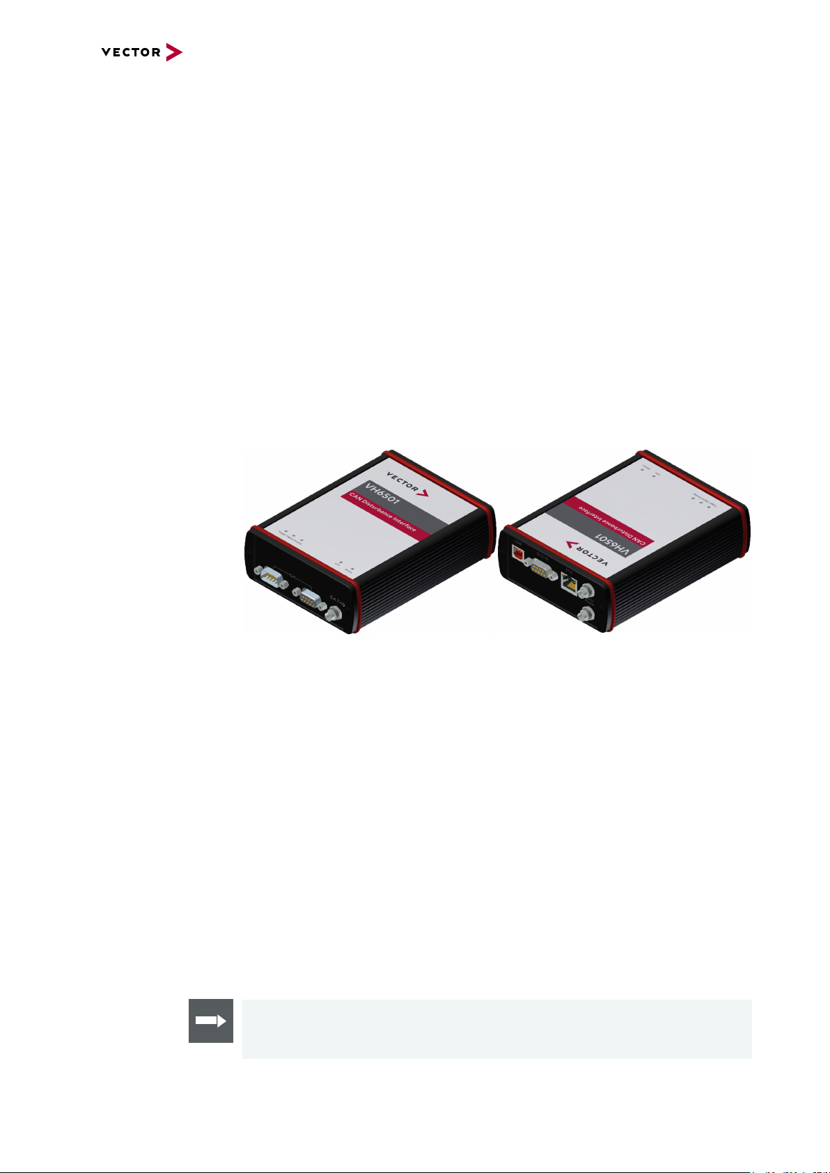
About the VH6501 With the VH6501, you can cause specific and reproducible disturbances on the CAN
bus, its physical properties and the logical level (recessive or dominant).
The VH6501 offers the following capabilities:
> Forcing freely definable sequences of recessive or dominant disturbance pulses
> Disturbance of specific frames via trigger
> Manipulation of the bit fields of CAN/CAN FD frames
Figure 1: VH6501
The main features of the VH6501 interface are:
> Full-featured CAN network interface
(can be used by several applications at the same time)
> Disturbance functionalities for CAN/CAN FD
(CANoe only)
> External trigger
> Second channel for dedicated digital-analog input/output tasks
> 5x LED indicating activities and status
> Software time sync
> Hardware time sync (via SYNCcableXL)
2.3 Accessories
Reference
Information on available accessories can be found in the separate accessories
manual on the Vector Driver Disk in \Documentation\Accessories.
VH6501 Manual Version 1.0 10
Page 11
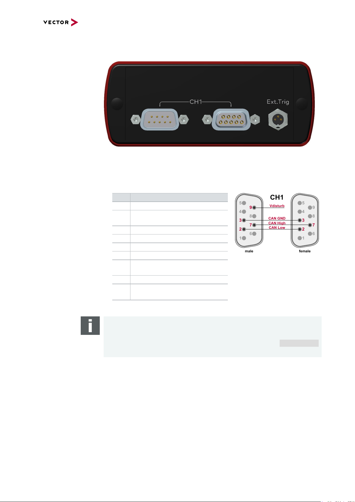
2.4 Connectors Bus Side
CAN GND
CH1
5
4
3
2
1
6
7
8
9
5
4
3
2
1
6
7
8
9
CAN High
CAN Low
Vdisturb
male
female
Front side
Figure 2: VH6501 with D-SUB9 connectors
> CH1 (2x D-SUB9)
The VH6501 has a female and a male D-SUB9 connector. The pin assignment of
both connectors is identical. Both connectors are interconnected.
2 Device Description
Pin Assignment
1 Not connected
2 CAN Low
CAN High*
3 CAN GND
4 Not connected
5 Not connected
6 Not connected
7 CAN High
CAN Low*
8 Not connected
9 V
disturb
-27V...+27V
(male only)
* CAN High and CAN Low can be electronically swapped at the female connector
Note
V
can be used to simulate external disturbances and electrical shorts by apply-
disturb
ing voltage between -27V...+27V against CAN GND (pin 3). If not required, pin 9
can be left unconnected. Further information can be found in section Technical Data
on page 19.
VH6501 Manual Version 1.0 11
Page 12
2 Device Description
PC
CAN
CH1
VH6501
Time Stamp Clock
USB
CAN
ECU
CAN
ECU
CAN
ECU
CAN
ECU
H
L
CANoe
CAN
CAN
CH1
VH6501
Time Stamp Clock
USB
CAN
ECU
CAN
ECU
CAN
ECU
CAN
ECU
CAN
PC
CANoe
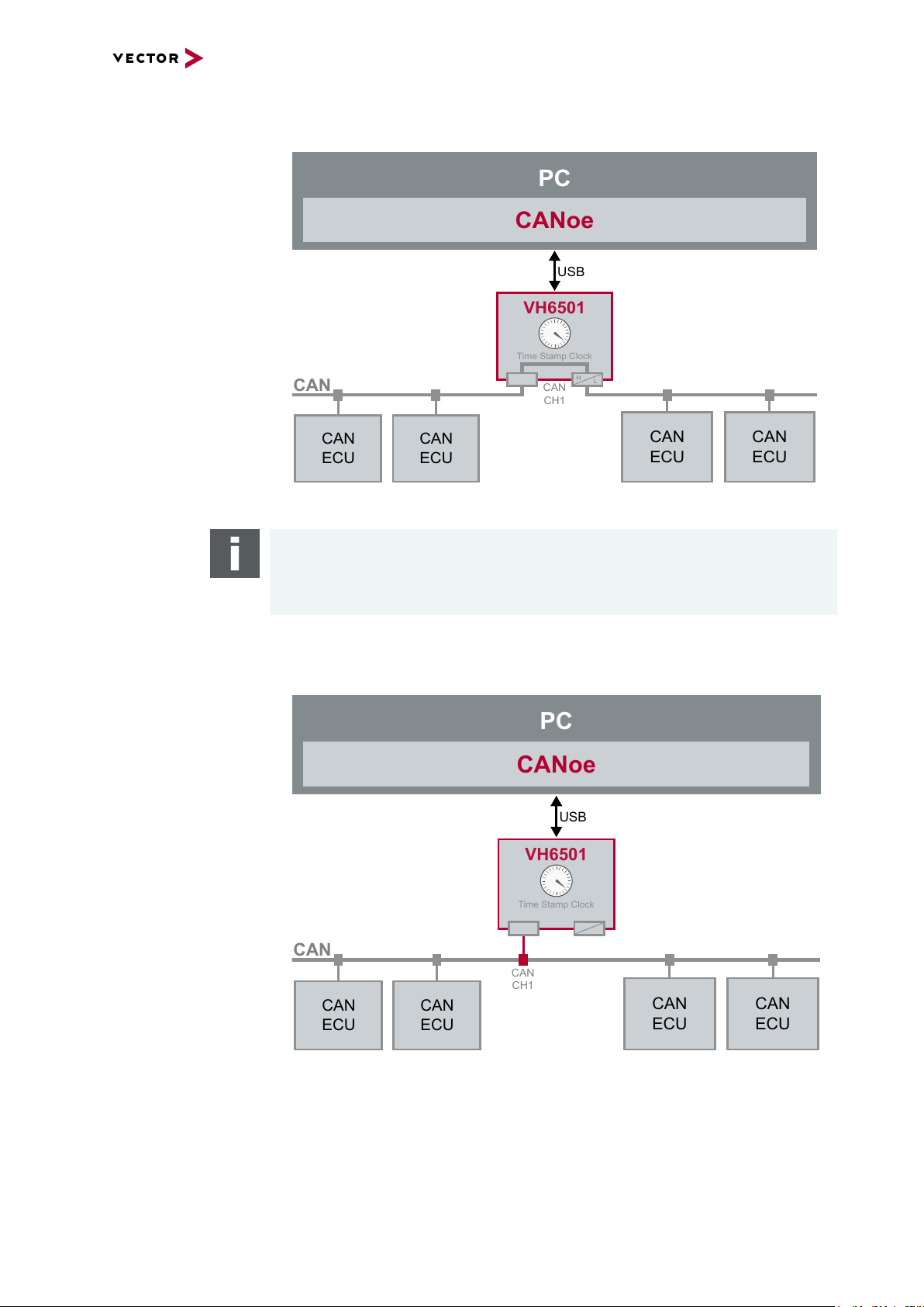
By connecting the device via both terminals, you can use the VH6501 as a bypass
interface that does not change the topology of the existing CAN network:
Figure 3: VH6501 as bypass interface
Note
The female and male connector are not split or isolated by the device, i.e. disturbances and triggers on the bus always affect both sides. The VH6501 cannot be
used as a gateway.
By connecting the device to an existing CAN network via one terminal, you can
use the VH6501 as network interface. This setup adds a new stub to the existing
CAN network.
Figure 4: VH6501 as network interface
VH6501 Manual Version 1.0 12
Page 13

2 Device Description
3 1
2
> External Trigger
This connector (Binder type 711) can be used to trigger other devices, e.g. an
oscilloscope.
Pin Assignment
1 Not connected
2 Trigger output
- 0V (low)
- 5V (high)
- 50 Ohm
- adjustable edge and pulse duration via CANoe
3 GND
VH6501 Manual Version 1.0 13
Page 14

2.5 Connectors USB Side
1
Analog GND
1
2
3
4
5
9
8
7
6
6
Digital In 0
5
Digital Out
Digital GND
Analog In
4
Digital In 1
8
9
Back side
Figure 5: Connectors on the USBside
Device connectors > USB
Connect your PC and the VH6501 via USB to install and to use the device. Use
the USB2.0 compliant cable found in the delivery (USB extension cables may generate faults between the PC and the device).
2 Device Description
Note
On USB connection, the powered device executes a calibration process as well
as a self diagnosis on the transceiver and the digital disturbance unit. This process takes approx. 1second.
> CH2-IO (D-SUB9)
Use this D-SUB9 connector for dedicated digital-analog input/output tasks. The
pin assignment for CH2 is as follows:
Pin Assignment
1 Analog In
2 Not connected
3 Not connected
4 Digital In 0 / Trigger In*
5 Digital In 1 / Trigger In*
6 Analog GND
7 Not connected
8 Digital Out
9 Digital GND
* You can use these pinsas external trigger to send user-defined or frame-based sequences. Furthermor e, it ispossible to use the digitalinputs as additionaltrigger enable for CANoe trigger conditions.An external trigger cannot be used if a trigger enable is configured. Use either Digital In 0 or
Digital In 1 as trigger/trigger enable. Parallel usage of both inputs isnot supported.
Reference
Details on the internal interconnection of the input/ouput pins can be found on
the next page.
VH6501 Manual Version 1.0 14
Page 15

2 Device Description
To Processor
Digital GND
Vcc
Digital GND Digital GND
Digital Input 0/1
Isolation
20k
Vref
200k
OUT
IN-
IN+
33 V
370 pF
From Processor
Digital Output
Digital GND
Isolation
33 V
370 pF
To Processor
Analog GND
Vcc
Analog Input
100k
1M
33 V
370 pF
Analog GND
22 pF
ADC
15k
10k
Analog GND
OUT
IN+
IN-
Isolation
INOUT
Details on CH2 The internal interconnection of the input/ouput pins is as follows:
Internal
interconnection of
digital input 0/1
Figure 6: Digital input 0/1
Internal
interconnection of
digital output
Internal
interconnection of
analog input
Figure 7: Digital output
Figure 8: Analog input
VH6501 Manual Version 1.0 15
Page 16

2 Device Description
VCC
1
2
3
Power
1
2
3
Sync
GND
Sync
GND
Power/Sync
Power/Sync
SYNC
GND
Power
3
1
2
Extended measuring
range of the
In normal operation, voltages up to 18 V can be applied and measured at the analog input. The cutoff frequency fc(-3 dB) for AC voltages is approx. 7.2 kHz.
analog input
For measurements above 18 V (max. 50 V), an external series resistor has to be
applied to the analog input. The series resistor R
input voltage U
to be measured and can be calculated as follows:
input
depends on the maximum
ext
The cutoff frequency for AC voltages is also affected by the external series resistor:
Examples 24 V 32 V 36 V 48 V
R
ext
R
(E96) 374 kΩ
ext
367 kΩ 856 kΩ 1100 kΩ 1833 kΩ
(24.12 V)
866 kΩ
(32.17 V)
1100 kΩ
(36.00 V)
1870 kΩ
(48.60 V)
fc(-3 dB) 1148 Hz 496 Hz 390 Hz 230 Hz
Device connectors
(continued)
> Host (Ethernet)
Host connector (100BASE-TX and 1000BASE-T). Reserved for future purposes.
> 2x Power/Sync (Binder connectors)
The VH6501 has two power/sync connectors (Binder type 711) which can be used
for time synchronization of different Vector devices (see section Time Synchronization on page 31) or for power. It does not matter which connector is used
to supply the device.
Figure 9: Internal wiring of the power/sync connector
Pin Assignment
1 Power supply (6 V … <60 V DC, typ. 12 V)
2 Synchronization line
3 Ground
VH6501 Manual Version 1.0 16
Page 17

2.6 LEDs
2 Device Description
Figure 10: Top LEDs on VH6501
> Trigger
Multicolored LED which indicates the trigger state.
Color Description
Off No active trigger.
Green Waiting for (multiple) trigger. This state remains until the last trigger
has been released in the application.
Red Self test error. Please try to reboot the device. If the error still remains,
please contact our support.
> Digital
Multicolored LED which indicates the state of the digital disturbances.
Color Description
Off No digital disturbance/sequence transmission.
Green Digital output in progress. For short sequences, this state remains at
least for 0.5s. For long sequences, this state remains as long as the
output is in progress.
Red At start-up: Calibration error. Please try to reboot the device. If the
error still remains, please contact our support.
At runtime: Error in digital disturbance/sequence transmission. Transmission is stopped due to high current, electrical short or overvoltage
of the transceiver. Please check your hardware setup and your CANoe
configuration.
> Analog
Multicolored LED which indicates the state of the analog disturbances.
Color Description
Off No analog disturbances.
Green Analog output in progress.
Red Error while analog disturbances selected. Possible reasons: high cur-
rent at electrical shorts or overvoltage at transceiver/resistors.
Affected resistors and electrical shorts will be automatically removed.
Please check your hardware setup and your CANoe configuration.
VH6501 Manual Version 1.0 17
Page 18

> CH1
Multicolored channel LEDs which indicates the bus activity for CAN.
Color Description
Green Data frames have been transmitted or received correctly.
Orange CAN: Error frames have been transmitted or received.
Red CAN: Bus off.
CAN: The flashing frequency depends on the bus load.
> Status
Multicolored LED indicating the device status.
Color Description
Green On: Running measurement.
Flashing: Device is ready for operation.
Orange On: Device executes update.
Flashing: Device start up.
Red Error. Device not working.
2 Device Description
VH6501 Manual Version 1.0 18
Page 19

2.7 Technical Data
CAN/CAN FD channel 1x D-SUB9 (TJA1057 Piggyback)
Analog input 10 bit
Digital input Range 0 V...32 V
Digital output Open Drain
Time stamps Resolution: 8 ns
PC interface USB 2.0
External power supply 6 V... <60 V DC
Power consumption Typical 7W
Temperature range
(ambient temp. of the device)
Relative humidity
of ambient air
Dimensions (LxWxH) Approx. 155 mm x 111 mm x 45 mm
Weight Approx. 600 g
Operating system requirements Windows 7 SP1 (32 bit / 64 bit)
Software requirements CANoe version 10.0 SP2 (or higher)
2 Device Description
CAN2.0: 2 MBit/s
CAN FD: up to 8 MBit/s
Input 0 V...18 V
Voltage tolerance up to 50 V
(with series resistor)
Sampling rate up to 1 kHz
Schmitt trigger high 2.7 V, low 2.2 V
Hysteresis 0.5 V
Input frequencies up to 1 kHz
External supply up to 32 V
Current max. 500 mA
Short circuit / over voltage protected
Accuracy (in device): 1 µs
Accuracy software sync: typ. 50 µs
Accuracy hardware sync: typ. 1 µs
Power-up: 9 V DC
Operation: -40 °C ... +60 °C
Storage: -40 °C ... +85 °C
15 %...95 %, non-condensing
Windows 8.1 (32 bit / 64 bit)
Windows 10 (64 bit)
VH6501 Manual Version 1.0 19
Page 20

2 Device Description
GND
RCAN High to Vbat/GND
disabled/
500 Ohm ...
23655 Ohm
Vdisturb GND
CCAN High to CAN Low
disabled/
100 pF ...
10 nF
E-Switch
E-Swap
CAN High
CAN Low
CAN High
CAN Low
or CAN Low
or CAN High
DSUB-9
male
DSUB-9
female
GND
GND
RCAN High to CAN Low
disabled/
500 Ohm ...
23655 Ohm
R
CAN Low to Vbat/GND
disabled/
500 Ohm ...
23655 Ohm
E-Switch
E-Switch
Vdisturb
Vdisturb Vdisturb
Changeable resistors
and capacitor
The following block diagram depicts the resistors and the capacitor which can be controlled via CANoe. In addition, CAN High and CANLow can be swapped at the
female connector if required.
Resistor values Ohm
500 525 570 605 735 800
905 1000 1495 1660 1965 2260
2485 3240 3720 4130 4945 9180
14505 23655
Capacitor values pF
100 126 133 223 440 460
485 510 566 600 643 688
762 825 909 1000 1303 1499
1803 2200 3197 4700 10000
Caution!
The VH6501 has an internal protection against incorrect resistor/voltage combination that could lead to electronic damages. If V
resistor is <=1kOhm, the affected resistor will be disabled .
Note
The internal protection does work as long as CAN High and CANLow are not externally fed.
Note
According to the technical specification of the TJA1057 transceiver, the range of the
voltage difference of CAN High andCAN Low is -27V ... 27V.
is >30V and the value of a
disturb
VH6501 Manual Version 1.0 20
Page 21

3 Getting Started
3 Getting Started
In this chapter you find the following information:
3.1 Driver Installation 22
3.2 Device Configuration 24
VH6501 Manual Version 1.0 21
Page 22

3.1 Driver Installation
3 Getting Started
General
information
The Vector Driver Disk offers a driver setup which allows the installation or the
removal of Vector devices.
Note
Please note that you will need Administrator Rights for the following steps.
Step by Step Procedure
1. Execute the driver setup from the autostart menu or directly from
\Drivers\Setup.exe before the device is connected to the PC with the
included USB cable.
If you have already connected the device to the PC, the Windows found new
Hardware wizard appears. Close this wizard and then execute the driver setup.
2. Click [Next] in the driver setup dialog. The initialization process starts.
VH6501 Manual Version 1.0 22
Page 23

3 Getting Started
3. In the driver selection dialog, select your devices to be installed (or to be uninstalled).
4. Click [Install] to execute the driver installation, or [Uninstall] to remove exist-
ing drivers.
5. A confirmation dialog appears. Click [Close] to exit. After successful instal-
lation, the device is ready for operation and can be connected to the PC with
the included USB cable and powered by supplying external voltage (e.g. with
an appropriate cable offered by Vector).
6. Install or update your CANoe to version 10.0 SP2 or higher.
VH6501 Manual Version 1.0 23
Page 24

3 Getting Started
3.2 Device Configuration
Configuration Before the installed device can be used in an application, it must be properly con-
figured for the needed use case. This configuration is done with the Vector Hardware
Config tool which comes with the driver installation. The tool can be found in Win-
dows | Start | Settings | Control Panel | Vector Hardware and manages all
installed Vector devices.
Reference
Further details on Vector Hardware Config can be found in the installation instruc-
tions (see section Vector Hardware Configuration on page 25).
Reference
Further details on the configuration with CANoe can be found in the according online
help.
VH6501 Manual Version 1.0 24
Page 25

4 Vector Hardware Configuration
4 Vector Hardware Configuration
In this chapter you find the following information:
4.1 General Information 26
4.2 Tool Description 27
4.2.1 Introduction 27
4.2.2 Tree View 28
VH6501 Manual Version 1.0 25
Page 26

4.1 General Information
4 Vector Hardware Configuration
Executing Vector
Hardware Config
Control Panel
Windows 7
Control Panel
Windows 8.1
After the successful driver installation you will find the configuration application
Vector Hardware in the Control Panel (see below). The tool gives you information
about the connected and installed Vector devices. There are also several settings that
can be changed.
Figure 11: Icon in Control Panel
> Category view
Windows Start | Control Panel | Hardware and Sound,
click Vector Hardware in the list.
> Symbols view
Windows Start | Control Panel,
click Vector Hardware in the list.
> Category view
<Windows key>+<X> | Control Panel | Hardware and Sound,
click Vector Hardware in the list.
> Symbols view
<Windows key>+<X> | Control Panel,
click Vector Hardware in the list.
Control Panel
Windows 10
> Category view
<Windows key>+<X> | Control Panel | Hardware and Sound,
click Vector Hardware in the list.
> Symbols view
<Windows key>+<X> | Control Panel,
click Vector Hardware in the list.
VH6501 Manual Version 1.0 26
Page 27

4.2 Tool Description
physical CH1
CAN
physical CH2
LIN
Vector Device 1
Vector Device 2
physical CH1
FlexRay
physical CH2
CAN
not assigned
l
ogical channel
CAN 1
Application
l
ogical channel
LIN 1
l
ogical channel
CAN 1
l
ogical channel
FlexRay 1
l
ogical channel
CAN 2
4.2.1 Introduction
Vector
Hardware Config
Figure 12: General view of Vector Hardware Config
4 Vector Hardware Configuration
Logical and physical
channels
Vector Hardware Config enables the channel configuration between installed Vector
devices and applications. Applications use so-called logical channels which are hardware independent and have to be assigned to real hardware channels.
Figure 13: Concept of channel assignments
VH6501 Manual Version 1.0 27
Figure 14: Channel assignment in Vector Hardware Config
Page 28

4.2.2 Tree View
4 Vector Hardware Configuration
Accessing
Vector devices
The tool is split into two windows. The left window has a tree view and lets you
access the installed Vector devices, the right window displays the details of the selection. The following nodes are available in the tree view:
Hardware The Hardware section lists the installed Vector devices. Each device item has phys-
ical channels which can be assigned to any number of logical channels (e.g.
CANalyzer CAN 1). A logical channel can be assigned to only one physical channel.
Figure 15: Hardware
Application In Application, all available applications are displayed in a tree view. According to
each application, the assignments of logical and physical channels are displayed in
the right part of the window. If no assignment exists, the information Not assigned
appears. The assignment can be edited via a right-click.
Figure 16: Application
VH6501 Manual Version 1.0 28
Page 29

4 Vector Hardware Configuration
Global settings Global settings contains global device configuration possibilities, e.g. software time
synchronization, transmit queue size, configuration flags or the number of virtual CAN
devices.
Figure 17: Global settings
Driver status Driver status offers an overall status information of devices and applications cur-
rently in use. You can see whether the channels are connected to the bus (online/offline) and whether the time synchronization is activated or not (Time-Sync-On/TimeSync-Off).
Figure 18: Dr iver status
VH6501 Manual Version 1.0 29
Page 30

4 Vector Hardware Configuration
License The License section contains information on all current available licenses (Vector bus
devices, Vector License USB dongle devices).
Figure 19: License
Reference
You will find a detailed description of Vector Hardware Config in the online help
(Help | Contents).
VH6501 Manual Version 1.0 30
Page 31

5 Time Synchronization
5 Time Synchronization
In this chapter you find the following information:
5.1 General Information 32
5.2 Software Sync 34
5.3 Hardware Sync 35
VH6501 Manual Version 1.0 31
Page 32

5.1 General Information
CAN
Vector
CAN Interface
CH1
CH2
Time Stamp Clock
PC
CANalyzer/CANoe
USB
5 Time Synchronization
Time stamps
and events
Generating
time stamps
Time stamps are useful when analyzing incoming or outgoing data or event
sequences on a specific bus.
Figure 20: Time stamps of two CAN channels in CANalyzer
Each event which is sent or received by a Vector network interface has an accurate
time stamp. Time stamps are generated for each channel in the Vector network interface. The base for these time stamps is a common hardware clock in the device.
Figure 21: Common time stamp clock for each channel
If the measurement setup requires more than one Vector network interface, a synchronization of all connected interfaces and their hardware clocks is needed.
Due to manufacturing and temperature tolerances, the hardware clocks may vary in
speed, so time stamps of various Vector devices drift over time.
VH6501 Manual Version 1.0 32
Page 33

5 Time Synchronization
CAN
FlexRay
Vector
CAN Interface
CH1
CH2
Time Stamp Clock
PC
Vector
FR Interface
CHA
CHB
Time Stamp Clock
sec
0.000000
0.100376
0.200382
0.300372
0.400406
0.500593
0.600242
sec
0.000000
0.1003
83
0.200
982
0.30
1456
0.40
2612
0.50
3885
0.60
4092
CANalyzer/CANoe
USB
USB
Figure 22: Example of unsynchronized network interfaces. Independent time stamps drift apart
To compensate for these time stamp deviations between the Vector network interfaces, the time stamps can be either synchronized by software or by hardware (see
next section).
Note
The accuracy of the software and hardware sync depends on the interface. Further
information on specific values can be found in the technical data of the respective
devices.
VH6501 Manual Version 1.0 33
Page 34

5.2 Software Sync
CAN
FlexRay
Vector
CAN Interface
CH1
CH2
Time Stamp Clock
Vector
FR Interface
CHA
CHB
Time Stamp Clock
synchronization
by software (PC clock)
sec
0.000000
1.100
356
1.200
362
2.300
362
2.400
356
3.500
353
3.600
362
PC
sec
0.000000
1.100
413
1.200
421
2.300
429
2.400
419
3.500
415
3.600
420
PC clock
CANalyzer/CANoe
USB
USB
5 Time Synchronization
Synchronization
by software
The software time synchronization is driver-based and available for all applications
without any restrictions. The time stamp deviations from different Vector network interfaces are calculated and synchronized to the common PC clock. For this purpose no
further hardware setup is required.
Figure 23: Time stamps of devices are synchronized to the PC clock
The setting of the software time synchronization can be changed in the Vector Hard-
ware Config tool in General information | Settings | Software time synchronization.
Figure 24: Switching on the software synchronization
> YES
The software time synchronization is active.
> NO
The software time synchronization is not active. Use this setting only if the Vector
network interfaces are being synchronized over the sync line or if only a single
device is used.
VH6501 Manual Version 1.0 34
Page 35

5.3 Hardware Sync
VN1630A
VN5610A
VN1640A
Multi
SYNCbox
external
VN1640A
USB PC
PC
VN7570
SYNCcable XL
SYNCcable XL
SYNCcable XL
SYNCcable XL
USB PC
Vector Devices
USB PC
USB PC
USB PC
VN5610A
VN8912A
Power
VN5610A
VN1640A
Multi
SYNCbox
external
VN1640A
USB VN8912A
USB PC
SYNCcable XL
SYNCcable XL
SYNCcable XL
SYNCcable XL
Power
Power
5 Time Synchronization
Synchronization
by hardware
A more accurate time synchronization of multiple devices is provided by the hardware
synchronization which has to be supported by the application (e.g. CANalyzer,
CANoe). Two Vector network interfaces can therefore be connected with the
SYNCcableXL (see accessories manual, part number 05018).
In order to synchronize up to five devices at the same time, a distribution box is available (see accessories manual, part number 05085).
Figure 25: Example of a time synchronization with multipledevices
Figure 26: Example of a time synchronization with VN8912A and additional devices
At each falling edge on the sync line which is initiated by the application, the Vector
network interface generates a time stamp that is provided to the application. This
VH6501 Manual Version 1.0 35
Page 36

5 Time Synchronization
CANalyzer/CANoe
CAN
FlexRay
Vector
CAN Interface
CH2
Time Stamp Clock
USB
Vector
FR Interface
CHB
Master Time Stamp Clock
synchronization
by hardware (SYNCcable)
sec
0.000000
1.10037
5
1.20038
1
2.30037
1
2.40040
5
3.50059
2
3.60024
1
CH1
CHA
sec
0.000000
1.100376
1.200382
2.300372
2.400406
3.500593
3.600242
PC
USB
allows the application to calculate the deviations between the network interfaces and
to synchronize the time stamps to a common time base (master clock) which is
defined by the application.
Figure 27: Time stamps are synchronized to the master clock
Note
The hardware synchronization must be supported by the application. For further
information please refer to the relevant application manual. Please note that the software synchronization must be disabled (see Vector Hardware Config | General
information | Settings | Software time synchronization) if the hardware synchronization is used.
VH6501 Manual Version 1.0 36
Page 37

Get More Information
Visit our website for:
> News
> Products
> Demo software
> Support
> Training classes
> Addresses
www.vector.com
 Loading...