

Page 1

VC-EVCC
Technical Reference
Version 1.1.0
Authors
Vector Informatik GmbH
Status
Released
Page 2

Technical Reference VC-EVCC
© 2021 Vector Informatik GmbH Version 1.1.0 2
based on template version 6.0.2
Document Information
History
Author
Date
Version
Remarks
dim
2020-12-14
0.1.0
Initial document
(based on VC-VCCU TechRef Version 9.2.0)
dim
2021-01-13
0.2.0
Updated after first review (by rpl)
dim/rpl/ssm
2021-01-14
1.0.0
Finalized for OR
dim
2021-03-31
1.1.0
Chapter 4.7 Remark about HSOUT added
Reference Documents
No.
Source
Title
[1]
DIN
DIN 70121:2014-12
[2]
DIN
DIN EN 61851-23 - Konduktive Ladesysteme für Elektrofahrzeuge
- Teil 23 Gleichstromladestationen für Elektrofahrzeuge (IEC 61851-23:2014)
[3]
DIN
DIN EN 61851-23 Berichtigung 1 - Konduktive Ladesysteme für
Elektrofahrzeuge - Teil 23 Gleichstromladestationen für
Elektrofahrzeuge (IEC 61851-23:2014/COR1:2016)
[4]
Vector
User Manual VC-EVCC (available within SOP)
[5]
ISO
ISO 15118-2:2014(E)
[6]
VDV
VDV 261 specification
[7]
SAE
SAE J3068 Electric Vehicle Power Transfer System Using a Three-Phase
Capable Coupler
Page 3

Technical Reference VC-EVCC
© 2021 Vector Informatik GmbH Version 1.1.0 3
based on template version 6.0.2
Safety Instructions
Caution
To avoid personal injuries and damage to property you have to read and understand
the following safety instructions and hazard warnings prior to installation and use of this
ECU. Keep this documentation always near the ECU.
Proper Use and Intended Purpose
Caution
The ECU may only be operated according to the instructions and descriptions of this
manual. The ECU is exclusively designed for use by skilled personnel as its operation
may result in serious personal injuries and damage to property. Therefore, only those
persons may operate the ECU who have understood the possible effects of the actions
which may be caused by the ECU. Users have to be specifically trained in the handling
(e.g. calibration) with the ECU, the applied embedded software and the system
intended to be influenced. Users must have sufficient experience in using the ECU
safely.
Hazard Warnings
Caution
The ECU may control and/or otherwise influence the behavior of control systems and
electronic control units. Serious hazards for life, body and property may arise, in
particular without limitation, by interventions in safety relevant systems (e.g. by
deactivation or otherwise manipulating the engine management, steering, airbag and/or
braking system) and/or if the ECU is operated in public areas (public traffic). Therefore,
you must always ensure that the ECU is used in a safe manner. This includes inter alia
the ability to put the system in which the ECU is used into a safe state at any time (e.g.
by “emergency shutdown”), in particular without limitation in the event of errors or
hazards. Furthermore, all technical safety and public law directives which are relevant
for the system in which the ECU is used must apply. Provided that serious hazards for
life, body and property may occur and before the use in public areas the system in
which the ECU is used must be tested according to recognized rules of engineering in
a non-public area.
Page 4

Technical Reference VC-EVCC
© 2021 Vector Informatik GmbH Version 1.1.0 4
based on template version 6.0.2
Contents
1 General .......................................................................................................................... 7
2 System Architecture ..................................................................................................... 8
2.1 Supported Peripherals ....................................................................................... 8
3 ECU ................................................................................................................................ 9
3.1 ECU Overview ................................................................................................... 9
3.2 Key ECU Characteristics .................................................................................. 10
4 Functional Overview ................................................................................................... 11
4.1 Power Line Communication ............................................................................. 11
4.1.1 Low Level Communication with EVSE ............................................. 11
4.1.2 AC Charging with Low Level Communication ................................... 11
4.1.3 DC Charging with High Level Communication .................................. 12
4.2 Stop Button ...................................................................................................... 12
4.3 StopCharge CAN Signal .................................................................................. 13
4.4 Generic Switch Input ........................................................................................ 13
4.5 Clamp 15 Signal Input ...................................................................................... 13
4.6 Status LEDs ..................................................................................................... 13
4.7 High Side Outputs ............................................................................................ 13
4.8 Reprogramming of the ECU Software .............................................................. 14
4.9 Self-Diagnostics and Fault Memory.................................................................. 14
4.10 ECU State Handling ......................................................................................... 14
4.11 Coupler Present Detection ............................................................................... 15
4.12 Locking / Unlocking the Combo2 and Combo1 Coupler ................................... 15
4.13 Temperature Monitoring ................................................................................... 15
4.14 Configuration of Software ................................................................................. 15
4.15 Value Added Services (VAS) ............................................................................ 16
4.16 Charging Arbitration ......................................................................................... 16
4.17 3-Phase Charging ............................................................................................ 16
4.18 Charging Schedules ......................................................................................... 16
4.19 Plug and Charge .............................................................................................. 16
4.20 Functional Safety ............................................................................................. 16
5 Industrialization .......................................................................................................... 17
6 Delivery Content ......................................................................................................... 18
6.1 ECU ................................................................................................................. 18
6.2 Packaging ........................................................................................................ 18
6.3 Software .......................................................................................................... 19
Page 5

Technical Reference VC-EVCC
© 2021 Vector Informatik GmbH Version 1.1.0 5
based on template version 6.0.2
6.4 Technical Documents ....................................................................................... 19
6.5 Quality Documents ........................................................................................... 19
7 Glossary and Abbreviations ...................................................................................... 20
8 Contact ........................................................................................................................ 21
Page 6

Technical Reference VC-EVCC
© 2021 Vector Informatik GmbH Version 1.1.0 6
based on template version 6.0.2
Illustrations
Figure 1-1 VC-EVCC (Representative Image) ............................................................. 7
Figure 2-1 System Overview Inlet Charging ................................................................. 8
Figure 3-1 VC-EVCC Interfaces ................................................................................... 9
Figure 6-1 VC-EVCC packed in Cardboard Package ................................................. 18
Tables
Table 1-1 Delivery Content ......................................................................................... 7
Table 3-1 VC-EVCC Key Characteristics .................................................................. 10
Table 4-1 Low Level Communication – Duty Cycle of CP PWM ............................... 11
Page 7
Technical Reference VC-EVCC
© 2021 Vector Informatik GmbH Version 1.1.0 7
based on template version 6.0.2
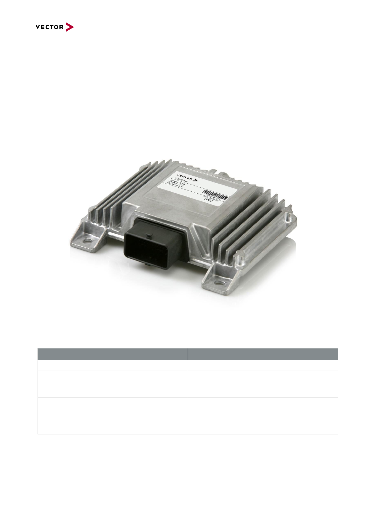
1 General
The Vector Controller - Electric Vehicle Communication Controller (VC-EVCC) is a generic
ECU for 24V environments.
It realizes electrical charging according to DIN SPEC 70121 see [1] and ISO 15118 see [5]
for power line communication (PLC) with the infrastructure.
The hardware is the VP-EVCC with an integrated flash bootloader. VC-EVCC includes a
modern MICROSAR stack with all relevant application modules to realize electrical charging
communication.
Figure 1-1 VC-EVCC (Representative Image)
The following parts are included in the delivery:
Part
Description
VC-EVCC
ECU with integrated software
Documentation
Customer receives a Technical Reference (this
document) as well as a User Manual and
Charging Sequence Diagrams, see chapter 6.4
Remaining Bus Simulation
CANoe bus simulation for the VC-EVCC for bus
test and evaluation purposes
CAN database description (dbc)
Diagnostic description file (cdd)
Table 1-1 Delivery Content
Page 8

Technical Reference VC-EVCC
© 2021 Vector Informatik GmbH Version 1.1.0 8
based on template version 6.0.2
2 System Architecture
The VC-EVCC is designed to be integrated into the vehicle with the following system
architecture.
Figure 2-1 System Overview Inlet Charging
2.1 Supported Peripherals
The supported peripherals for inlet charging depend on the charging standard:
> Charging standard CCS-1 (Combo 1 Inlet):
> Phoenix CCS Type 1 Inlet EV-T1GBIE12-1AC series (inlet w. lock)
> Phoenix CHARX T1HBI12 series (inlet w. lock)
> Charging standard CCS-2 (Combo 2 Inlet):
> Amphenol HVCO-CF6-ATR8-SF series (inlet) & C-NEVDC12V_ELOCK (lock)
> Phoenix CCS Type 2 Inlet EV-T2GBIE12-1AC series (inlet w. lock)
> Phoenix CCS Type 2 Inlet EV-T2GBIE12-3AC series (inlet w. lock)
> Phoenix CHARX T2HBI12 series (inlet w. lock)
> REMA REV-2C series (inlet) & REMA CCS Actuator (lock)
> Inlet manufacturers are continuously developing inlets and adapting them to the new
requirements. For this reason, the range of available inlets is also changing. Once
other inlets are used than mentioned above, please contact the Vector support in order
to check the compatibility with the VC-EVCC.
Page 9

Technical Reference VC-EVCC
© 2021 Vector Informatik GmbH Version 1.1.0 9
based on template version 6.0.2
3 ECU
This chapter contains an overview about the VC-EVCC. A detailed description of the
electronics and housing can be found in the User Manual of the VC-EVCC.
3.1 ECU Overview
The following diagram and tables give an abstract overview of the interfaces of the hardware.
Note
There are many different configuration options for the hardware of the VC-EVCC. The
following figure shows the configuration of the VC-EVCC.
Figure 3-1 VC-EVCC Interfaces
Page 10

Technical Reference VC-EVCC
© 2021 Vector Informatik GmbH Version 1.1.0 10
based on template version 6.0.2
3.2 Key ECU Characteristics
Parameter
Description
CPU
SPC564B74L7, 120MHz
Memory
3,0 MB Code-Flash, 4x16 kB Data-Flash, 192
kB RAM
Voltage range
8V … 32V (ISO 16750, Code E)
Overvoltage 2 min
48V
Connector
Molex CMC36 Hybrid Sealed (36 Pins)
Communication
3x CAN 2.0B (incl. shielding)
1x PLC – Power Line Communication based on
IEC61851
I/O
Extensive Inputs and Outputs typically needed
for in vehicle powerline charging systems
Temperature Range
-35°C … +85°C (ISO 16750, Code H)
Typical Current Consumption without loads
150mA
Quiescent Current
203µA
Weight
560 g
IP protection
IP6K6K / IP6K7 / IP6K9K (not valid for
unsealed housing
Functional Safety
Safety targets according to ASIL B
Table 3-1 VC-EVCC Key Characteristics
Page 11

Technical Reference VC-EVCC
© 2021 Vector Informatik GmbH Version 1.1.0 11
based on template version 6.0.2
4 Functional Overview
4.1 Power Line Communication
4.1.1 Low Level Communication with EVSE
According to [2] and [3] a low-level communication via PWM on the CP pin is supported.
The following PWM duty cycles are valid:
Duty Cycle of CP PWM
Description
0% <= DC < 3%
No charging allowed
3% <= DC <= 7%
Usage of high-level protocol according to ISO
15118 and DIN 70121. Charging without this
high-level protocol is not possible.
7% < DC < 8%
No charging allowed
8% < DC < 10%
Max current consumption is 6A
10% <= DC <= 85%
Available current = Duty Cycle * 0,6A
85% < DC <= 96%
Available current = (Duty Cycle – 64) * 2,5A
96% < DC <= 97%
Max current consumption is 80A
97% < DC <= 100%
No charging allowed
Table 4-1 Low Level Communication – Duty Cycle of CP PWM
4.1.2 AC Charging with Low Level Communication
With the low-level communication, AC charging can be performed in the following sequence:
> Lock coupler after plugged into inlet
> Establish communication to EVSE via CP
> Get charging clearance from vehicle
> Start charging
> Continuous monitoring of charging progress
> Vehicle state monitoring; Stop button monitoring; Temperature monitoring; EVSE
communication; Self-diagnostic of actuators/sensors
> Stop charging
> Release coupler after a pressed stop button or a CAN signal
Note
For detailed information, please refer to the AC Charging diagram.
Page 12

Technical Reference VC-EVCC
© 2021 Vector Informatik GmbH Version 1.1.0 12
based on template version 6.0.2
4.1.3 DC Charging with High Level Communication
According to [1] and [5], high level communication for DC charging is supported. The
supported charging profile is EIM (External Identification Means).
The DC charging is done in the following sequence:
> Lock coupler after plugged into inlet
> Get charging clearance from vehicle
> Session setup with EVSE
> Parameter exchange with EVSE (charging mechanism, schedule tables…)
> Isolation measurement with EVSE
> Start pre-charge
> Start charging
> Continuously monitoring of charging progress
> Vehicle state monitoring; Stop button monitoring; Temperature monitoring; EVSE
communication; Self-diagnostic of actuators/sensors
> Stop charging
> Release coupler after a pressed button or StopCharge CAN signal
Note
For detailed information, please refer to the DC Charging diagram.
4.2 Stop Button
The button is monitored continuously when the VC-EVCC is active. If the button is
pressed, the charging is stopped.
Alternatively, the VC-EVCC checks a CAN signal for charge abortion information.
Page 13

Technical Reference VC-EVCC
© 2021 Vector Informatik GmbH Version 1.1.0 13
based on template version 6.0.2
Caution
The voltage levels at the inlet power supply pins are not checked by the VC-EVCC prior
to unlocking the coupler. This must be done by the other system components and
controlled by the CAN signal which sets the signal
VCVCCU_Vehicle_PlugUnlockPermission.
Please refer to the UserManual_VC-EVCC for details (chapter TBD) [4].
4.3 StopCharge CAN Signal
The StopCharge CAN Signal is monitored continuously when the VC-EVCC is active and
the feature is activated. If the StopCharge CAN Signal is set to pressed, the charging is
stopped.
4.4 Generic Switch Input
An additional digital input to connect an additional button. Besides, the generic input is used
for the charging arbitration.
4.5 Clamp 15 Signal Input
For a discrete wakeup of the ECU instead of a CAN network wakeup the Clamp 15 signal
input may be used to wake the ECU and keep it awake. Clamp 15 has to be available during
the whole OppCharge sequence.
4.6 Status LEDs
The charging status can be displayed via three LEDs which can be controlled via CAN
messages by an external ECU. For more details please refer to the User Manual of the VC-
EVCC.
4.7 High Side Outputs
Three High Side Outputs are available for general purposes which can be controlled via
CAN signals by an external ECU. For more details, please refer to the User Manual of the
VC-EVCC.
Caution
If the VC-EVCC suffers from an unintentional GND contact loss, the freewheeling diode
inside HSOUT4 may lead to an unexpected flow of current from HSOUT4 via its
external load to GND.
As this may lead to undefined behavior of the external load (e.g. a BMS relay), the
usage of HSOUT4 must be considered with care.
If in doubt, please contact the Vector support.
Page 14

Technical Reference VC-EVCC
© 2021 Vector Informatik GmbH Version 1.1.0 14
based on template version 6.0.2
Caution
If the High Side Outputs of the VC-EVCC are used, measures must be taken to ensure
a load current greater than 15mA (HSOUT0, HSOUT1) respectively 330mA (HSOUT4).
An appropriate load resistor must be calculated depending on the supply voltage.
Otherwise, the VC-EVCC will detect an OpenLoad error which leads to a switch-off of
the respective High Side Output.
4.8 Reprogramming of the ECU Software
Reprogramming will be done via diagnostic CAN (CAN0). Therefore, the ISO 14229 UDS
protocol will be used. The following reprogramming features are supported:
Download of one logic block of application and basic software
Download of one logic block of Ethernet transceiver firmware
Download of CWG software
Security via CRC (no signature)
Updater for the flash bootloader itself is not supported
4.9 Self-Diagnostics and Fault Memory
The VC-EVCC continuously monitors all relevant inputs and outputs. The information is
available in the self-diagnostic messages of the outputs.
In addition to that the self-diagnostic also includes faults during charging or in case of internal
faults.
Furthermore, the VC-EVCC includes a fault memory that can store several DTCs.
4.10 ECU State Handling
An ECU wakeup is performed due to following reasons:
Clamp 15 signal
CAN wakeup
Stop button pressed
Vehicle coupler connected
Control Pilot Pin active
Wake up from real time clock
Page 15

Technical Reference VC-EVCC
© 2021 Vector Informatik GmbH Version 1.1.0 15
based on template version 6.0.2
If the ECU is active there are the following awake reasons possible to stay active:
Clamp 15 signal
Control Pilot activity
CAN active
Active Diagnostic session
Active OppCharge charging session
In all other cases, the VC-EVCC will go to sleep.
4.11 Coupler Present Detection
For the coupler present detection, the proximity pin (PP) or the PWM signal of the control
pilot line (CP) is used.
4.12 Locking / Unlocking the Combo2 and Combo1 Coupler
The locking / unlocking of the Combo2 and Combo1 coupler is done with a motor, controlled
by an H-Bridge.
The coupler will be locked when:
> A vehicle coupler is detected and
> A CAN lock signal is received
> If the coupler was unlocked but not removed after a certain time
The locking is performed after a specified time the coupler was detected.
The coupler will be unlocked when:
> An unlock message is received on CAN and
> The charging stop button is pressed or
> [in case of Combo1] the S3Switch is pressed or
> The StopCharge CAN Signal is pressed
4.13 Temperature Monitoring
The supported Combo2 and Combo1 vehicle inlets have up to 3 temperature sensors:
> One sensor is used for AC charging
> Two sensors are used for DC charging
4.14 Configuration of Software
The VC-EVCC allows configurations of the firmware on the diagnostic channel:
Baudrate adjustment between 250 kBaud, 500 kBaud and 1 MBaud on the J1939 CAN
Automatic switch of high side output to wakeup other ECUs
Page 16

Technical Reference VC-EVCC
© 2021 Vector Informatik GmbH Version 1.1.0 16
based on template version 6.0.2
Charging stop user interaction via charging stop button or dedicated CAN message
Configurable message cycle times of several messages
Security Key Constant
4.15 Value Added Services (VAS)
Value added service are additional service which are not part of the V2G communication
and not mandatory for charging. The VC-EVCC supports VAS according to ISO 15118-2 [5]
and VDV 261 [6].
4.16 Charging Arbitration
The charging arbitration enables the operation of two VC-EVCCs on the same CAN channel.
It targets use cases which require two charging inlets (two VC-EVCCs) per vehicle but only
one charging inlet is used for charging at a time.
For charging arbitration, the VC-EVCC provides the following configurations on the
diagnostic channel:
> Configuration of Primary Source Address
> Configuration of Secondary Source Address
> Activation/Deactivation of Charging Arbitration
For more details, please refer to the User Manual of the VC-EVCC [4].
4.17 3-Phase Charging
The VC-EVCC supports 3-Phase Charging ‘LIN over CP’ according to SAE J3068 [7].
4.18 Charging Schedules
The VC-EVCC supports Charging Schedules according to ISO15118 [5].
4.19 Plug and Charge
The VC-EVCC supports Plug and Charge (‘PnC’) according to ISO15118-2 [5].
4.20 Functional Safety
The VC-EVCC is developed to fulfill functional safety according to ASIL_B.
Page 17

Technical Reference VC-EVCC
© 2021 Vector Informatik GmbH Version 1.1.0 17
based on template version 6.0.2
5 Industrialization
This section describes the elements of the VC-EVCC industrialization, which are installed
and released by Vector:
> Production engineering
> Production requirements
> Quality requirements
> Control plan
> P-FMEA
> D-FMEA
> Production installation
> Series Production line for electronic parts
> Automated Optical Inspection (AOI)
> In Circuit Test (ICT)
> Production line for mechanical assembly
> Leakage test
> Generic End of Line Test (EOL)
> Production Specification
> The common part of production is described in the Production Specification and is
released by Vector.
Note
The documents listed in this chapter are for internal documentation of processes only.
They are not released for external use or delivery to Customer.
Page 18

Technical Reference VC-EVCC
© 2021 Vector Informatik GmbH Version 1.1.0 18
based on template version 6.0.2
6 Delivery Content
The VC-EVCC hardware is packed in a single packaging and shipped as off-the-shelf
product from Vector warehouse. The standard delivery for software and documents takes
place via download link as ZIP file from the Vector homepage.
6.1 ECU
Based on the offer and order the customer will receive an off-the-shelf product:
> VC-EVCC Series (No.:89524)
> VC-EVCC Evaluation (No.:89523)
The ECUs are stored inside the cardboard package. The goods will be extracted from the
stock as per ordered quantity and packed individually within our logistics department in
Stuttgart.
6.2 Packaging
The VC-EVCC is packed in a single box (non ESD) with the following description:
> Approximate sizing of a single package: 250 mm x 191 mm x 64 mm (L x W x H,
approximately)
> Approximate weight: 0,74 kg (approximately, Cardboard 0,18 kg + ECU 0,56 kg)
Figure 6-1 VC-EVCC packed in Cardboard Package
Several ECUs in one shipment are packed in overpacks, e.g.:
> 5 ECUs: Approximately 450 x 320 x 320 mm, 5 kg
> 10 ECUs: Approximately 560 x 360 x 310 mm, 10 kg
> 25 ECUs: Approximately 800 x 600 x 400 mm, 25 kg
Page 19

Technical Reference VC-EVCC
© 2021 Vector Informatik GmbH Version 1.1.0 19
based on template version 6.0.2
6.3 Software
> VC-EVCC for vFlash package (.vflashpack)
> CANoe project (.cfg)
> CAN J1939 communication matrix (.dbc)
> Diagnosis CAN communication matrix (.dbc)
> Diagnosis description file for CANdela Studio (.cdd)
6.4 Technical Documents
> Release Notes VC-EVCC (.pdf)
> Technical Reference VC-EVCC (.pdf)
> User Manual VC-EVCC (.pdf)
> Safety Manual VC-EVCC (.pdf)
> Charging Sequence Description AC/DC (.pdf)
> Envelope model 3D (STEP)
> VC-EVCC technical drawing (2D)
> VV-Report VP-EVCC (.pdf) *
6.5 Quality Documents
> No additional quality documents will be provided
*will be provided if required
Page 20

Technical Reference VC-EVCC
© 2021 Vector Informatik GmbH Version 1.1.0 20
based on template version 6.0.2
7 Glossary and Abbreviations
Term
Description
AC
Alternating Current
AOI
Automated Optical Inspection
BMS
Battery Management System
CAN
Controller Area Network
CCS
Combined Charging Standard
.cdd
CANdela Diagnostic Description File
CP
Control Pilot
CPU
Central Processing Unit
CRC
Cyclic Redundancy Check
CWG
CAN-WiFi-Gateway
DC
Direct Current
DCB
Disconnecting Circuit Breaker
ECU
Electronic Control Unit
EMC
Electromagnetic Compatibility
EV
Electric Vehicle
EVSE
Electric Vehicle Supply Equipment
(D- / P-) FMEA
(Design / Process) Failure Mode and Effects Analysis
ICT
In Circuit Test
LED
Light Emitting Diode
PLC
Power Line Communication
PE
Physical Earth
PP
Proximity Pin / Plug Present
PWM
Pulse-Width Modulation
RAM
Random Access Memory
RESS
Rechargeable Energy Storage System
UDS
Unified Diagnostic Services
V2G
Vehicle-to-Grid
VAS
Value Added Services
VC-EVCC
Vector Controller – Electric Vehicle Communication Controller
VDV
Verband Deutscher Verkehrsunternehmen
Page 21

Technical Reference VC-EVCC
© 2021 Vector Informatik GmbH Version 1.1.0 21
based on template version 6.0.2
8 Contact
Visit our website for more information on
> News
> Products
> Demo software
> Support
> Training data
> Addresses
www.vector.com
 Loading...