

Page 1
Network Printer
V4.1 and above
Installation & Commissioning
Manual
MVEC-03 Issue 3.0 July 2008
Page 2

Page 3

Vector printer Installation and Commissioning Manual. 3
CONTENTS.
Page
Introduction…………………………………………………..……………………………………...…..3
ESD Precaution…….………………………...…………………………..………………………..…..3
Installation (Retro-fit)…………………………….…………………………………………….....…4
Replacing the paper roll ………………..……………………………………………………...….4
Powering up the printer ……………..……………………………………………………...…….5
Printer indications …………………………………………………………………...…………..5
Paper feed………………………………………………………………………………...……...5
Print options………………………………………..…………………………………………...………5
Other Printouts ………………………………………………………………………………….........6
Trouble shooting………………………………….….……….…….……………………………..….6
Drawing S1620 Connection Diagram..……………………...………………………….……..7
Technical Specification………………………………………………………………...………..….8
Page 4

Vector printer Installation and Commissioning Manual. 4
INTRODUCTION
The Vector printer is an add-on option for the Vector analogue addressable fire alarm system .
The printer is integrated into a control panel lid and operates on a network basis. Therefore it can
be used to produce print outs for any panel on the network. The Printer can be configured to
record all events from a network or just from a local panel only . Up to 16 printers can be
connected to any individual network.
The thermal printer produces hig h speed clear prints. No ink ribbon is required, only a thermal
paper roll.
The printer will record all fire events, fault events , alarm log , fault log and user log, control panel
parameters and disablements. The printer is also used to log engineer tests and produce a
maintenance report.
The printer is complete with a paper feed button and ‘paper out’ indicator. Two printer options are
available via an on board dual in line switch.
1) system wide or local printing.
2) suppress fault printing or print all faults.
ESD Precaution
Electronic components are vulnerable to damage by Electrostatic Discharges (ESD). An ESD
wrist strap, suitably grounded, should be worn at all times when handling pcbs. These wrist straps
are designed to prevent the build up of static charges, not only within a persons body, but on
many other materials.
ESD damage is not always evident immediately, faults can manifest themselves at anytime in the
future.
All pcbs should be stored in static shielded bags (silvered) for safe keeping, when not mounted in
the control panel. Do not use “black” or “pink” bags and never allow pcbs to come in contact with
bubble wrap or expanded polystyrene (packing chips).
Page 5
Vector printer Installation and Commissioning Manual. 5
INSTALLATION.
Installing the printer (retro-fit)
Under normal circumstances the printer will be factory fitted to the control panel. If for any reason
the printer is being replaced or retro-fitted to the control panel:-
Firstly remove the existing control panel lid. Disconnect the key-switch and earth link cables from
the back box, Once removed lift away the lid and fit the new lid in a similar manner, Terminate
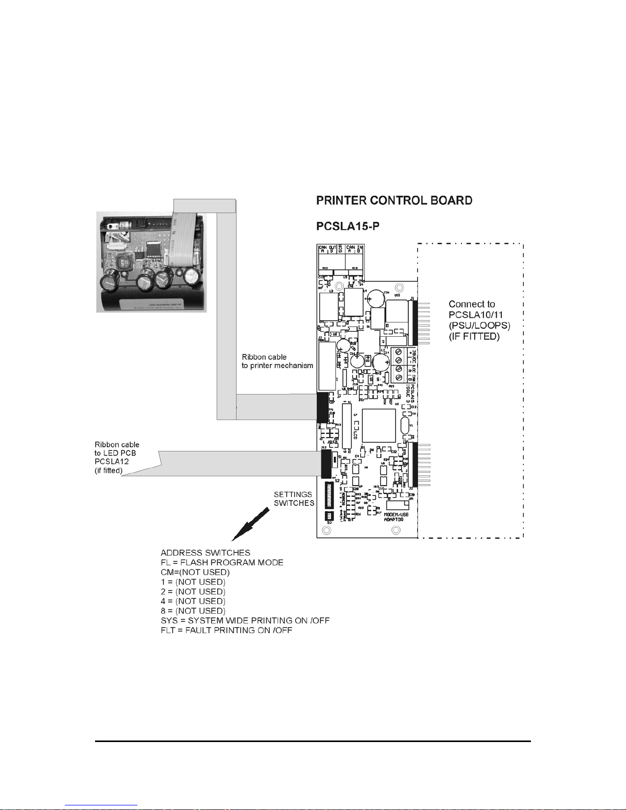
cables in line with the Drawing S1620 (see back of manual).
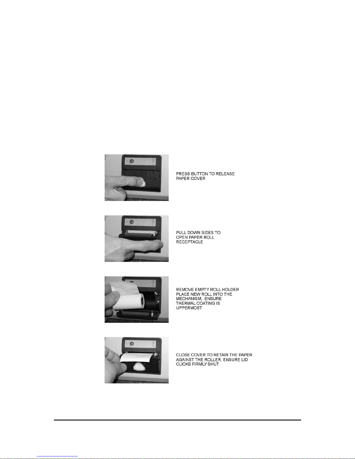
Replacing the paper roll
The printer requires special thermal paper which can be obtained from the suppliers. To fit the
paper roll:-
Page 6

Vector printer Installation and Commissioning Manual. 6
INSTRUCTIONS
Powering up the printer
Once all the settings are checked the cabling connected and the paper roll installed, the printer
may be powered up (along with the control panel) . The printer will record a message:-
Vector M system (or local) Printer V4.0
Panel xx
Fault printing disabled
This message reflects the switch settings.
In order to reduce traff ic on the communications bus, the text m essages reside in a mem ory on
the printer interface. These are automatically updated by the system.
After a short time the printer may record a message saying :-
Device names updated, panel xx.
This message will be printed each time a name is changed in any panel on the network either by
download or manual editing . If communications are not b eing re ceive d b y the printer the mess age
will read :-
Comms disconnected
Network wide events will be printed, but device text is only printed for the local panel. A ’Network
Wide’ printer will not print individual device text messages.
Indications
Printer Supply
Green light will be illuminated when power is at the printer interface.
No paper
A yellow LED on the printer mechanism will pulse if paper is not present in the printer rollers.
NOTE:- the mechanism will not attempt to print if paper is not fitted.
Paper feed button
Pressing this button will advance the paper. .
Print options
In the Vector control panel menu, item no 7. PRINT OPTIONS, four options are available:-
1. PRINT ALARM LOG. Prints all alarms and evacuations in the form,
FIRE ADD 013 OPT ZONE 03 11:39 13/04.
alarm address type zone time date dd/mm
2. PRINT FAULT LOG . Prints all faults in the form.
UNASSIGNED ADD 013 OPT 11:39 13/04.
fault address type time date dd/mm
3.PRINT USER LOG. Prints type, time and date of user actions
.
Page 7

Vector printer Installation and Commissioning Manual. 7
Print options cont’d
4. PRINT DEVICE PARAMETERS. Prints device information in the form
001 OPT ZONE 01 G****
address type zone groups
SMOKE DETECTOR GROUND FLOOR
text message.
This print will report all devices assigned to the panel selected.
With one option above chosen, select the required panel and loop number on the network by scroll-
ing the panel number from 00 to 15, and scrolling the loop number 1 - 4. The selection should default
to the local panel. Press button 5 to print . Press menu button to exit.
Other printouts
The printer will print all alarms and faults (if selected) in real time in the form:-
**********FIRE**********
FIRE PANEL 00 LOOP 01 ZONE 04
TYPE MAN ADDRESS 020 22:48 04/01
MANUAL CALL POINT TEXT MESSAGE HERE
Test mode . When test mode is used the printer will record the devices tested:-
TEST ADD 020 MAN ZONE 04 22:43 04/01
TEST ADD 019 OPT ZONE 04 22:41 04/01
Maintenance check. When this engineering mode is used, the printer will record devices with an ana-
log value above the threshold selected, They are printed as the display is manually scrolled.
Maintenance P00 OPT Ana 34
Maintenance P00 ION Ana 32
P00 refers to the panel number , Ana 34 refers to the analog value returned by the device.
Troubleshooting
The printer will not print :- is there paper available, is the printer address correct. Are dil switch op-
tions set correctly. Is panel V4.0 or above, is paper correctly installed.?
(i.e. coating upwards).
Comms disconnected:- Is PCB connected correctly.
‘Printer supply’ led out:- Check supply fuse
Page 8
Vector printer Installation and Commissioning Manual. 8
Drawing S1620 showing printer connection details
Page 9
Vector printer Installation and Commissioning Manual. 9
TECHNICAL SPECIFICATION
Specification.
Power supply 27.6 V DC ± 2V (15 Watts Max )
supply fuse 1 Amp quick blow nanofuse Replace only with similar type
Power consumption 42 milliamps in quiescent
Power consumption 500 milliamps peak during printing
Printing method High speed thermal
Paper Thermal coated 58mm x 25 metre roll
THM582512
Signalling CAN 2.0 data bus
Max 16 printers per network
Dimensions (lid mount) 90mm x 60mm x20mm pod on door front
Dimensions (stand alone) 320mm high x 160mm wide x 85mm deep Weight 2.4 Kg
Cabling FP200 or equivalent (maximum capacitance
1µF, maximum inductance 1 millihe n ry)
Cable glands must be used.
Page 10

 Loading...