

Page 1
INSTALLATION MANUAL
SWING GATE
AUTOMATION
Page 2

CENTURIONSYSTEMShasbeen manufacturingautomaticgate systems since 1987, andis committed to
providingreliable,costeffectivesolutionsin thefieldof accessautomation.
CENTURIONstrivestogiveserviceand backup second to none. Ourengineersareavailableto give sales
support,installationtraining,andanswersto technicalorinstallationproblems.
Theequipmentisinstalledworldwideandis availablethroughanetworkof distributors.
CENTURIONisanISO9001 - 2000 registered company,continually looking at updating its products in line
withworldtrendstoensurethatitsproductswillprovidecustomersatisfaction.
Furtherinformationis availableonour websitewww.centsys.co.za
©CENTURIONSYSTEMS (PTY) LTD
CenturionSystems(Pty)Ltd. reservestheright tomakechangesto theproductsdescribed inthismanualwithout noticeandwithout obligation
of Centurion Systems (Pty) Ltd. to notify any persons of any such revisions or changes. Additionally, Centurion Systems (Pty) Ltd. makesno
representationsorwarrantieswithrespectto thismanual.
Nopart ofthisdocument maybe copied, storedin aretrievalsystem ortransmittedin anyformor byany meanselectronic,mechanical,optical
orphotographic,withouttheexpressprior writtenconsentofCenturionSystems(Pty) Ltd.
Company Profile
Company Profile
Pag e 2
Page 3

Page 3
Table of Contents
Table of Contents
Important Safety Instructions...........................................................4
General Description..................................................................5
Icons Used In This Booklet.............................................................5
Specifications . . . . ...................................................................6
Package Contents....................................................................9
Required Tools & Equipment ..........................................................13
Site Considerations .................................................................14
Cabling Requirements...............................................................17
Operator Installation.................................................................18
Inward swing gates..................................................................22
Outward swing gates ................................................................24
Electrical Set-up....................................................................26
Control box Installation...............................................................26
Additional Features. .................................................................28
Menu navigation map................................................................29
Controller Features ..................................................................31
Factory Defaults Schedule............................................................39
Description of terminal functions.......................................................41
LED Indicator Lights.................................................................43
Buzzer Feedback...................................................................43
Charger & pillar ligh connections.......................................................44
Determine Gate Swing Angle..........................................................45
Wiring Diagram for Motor M (MTR M) ...................................................46
Wiring Diagram for Motor S (MTR S) ....................................................47
Wiring Diagram for Safeties...........................................................48
Wiring Diagram for Other Inputs........................................................50
Allowable Wind Loading..............................................................52
Installation Handover................................................................53
Page 4
Important Safety Instructions
Important Safety Instructions
Page 4
To ensure the safety of people,it is important that you readall the following
instructions. Incorrect installation or incorrect use of the product could
causeseriousharmto people.
Theinstaller, being eitherprofessionalor DIY, isthelast person onthesite that canensurethat the operatorissafely
installed,andthat thewholesystemcanbeoperatedsafely.
MOVING GATE CAN CAUSE
SERIOUS INJURY OR DEATH
KEEP CLEAR. GATE MAY MOVE AT
ANY TIME. DO NOT ALLOW
CHILDREN TO PLAY IN AREA OR
OPERATE GATE .
WAR NI NG
ATTENTION
WARNINGS FOR THE INSTALLER
1. CAREFULLYREAD AND FOLLOWALL INSTRUCTIONS 14. Safety devicesmust be fitted to the installation to guard
beforebeginningtoinstalltheproduct. against mechanical movement risks such as crushing,
draggingandshearing.
2. All installation, repair, and service work to this product
mustbedone byasuitably qualifiedperson. 15. It is recommended that at least one warning indicator
lightbefitted toeverysystem.
3. Do not activate your gate opener unless you can see it
and can determine that its area of travel is clear of 16. Always fit the warning signs visibly to the inside and
people,pets,or otherobstructions. outsideofthe gate.
4. NO ONEMAY CROSS THEPATHOF A MOVING GATE. 17. The installer must explain and demonstrate the manual
Always keep people and objects away from the gate operationof thegate incase ofan emergency,and must
anditsarea oftravel. handtheUser/Warningsguideover totheuser.
5. NEVER LET CHILDRENOPERATE OR PLAYWITH THE 18. Explain these safety instructions to all persons
GATE CONTROLS, and do not allow children or pets authorized to use this gate, and be sure that they
nearthegate area. understand the hazards associated with automated
gates.
6. Securealleasilyaccessedgate openercontrolsin order
topreventunauthorizeduse ofthegate. 19. Do not leave packing materials (plastic, polystyrene,
etc.) within reach of children as such materials are
7. Do not in any way modify the components of the
potentialsourcesofdanger.
automatedsystem.
20. Dispose of all waste products like packaging materials,
8. Do not install the equipment in an explosive
wornoutbatteries,etc,accordingtolocal regulations.
atmosphere:the presenceof flammablegasor fumesis
aseriousdanger tosafety. 21. Always check the obstruction detection system, and
safetydevicesforcorrectoperation.
9. Beforeattemptingany workon thesystem, cutelectrical
poweranddisconnectthe batteries. 22. CenturionSystems does not acceptany liability caused
byimproperuse oftheproduct,orfor useotherthan that
10. Themainspower supply of theautomated system must
forwhichthe automatedsystemwasintended.
be fitted with an all-pole switch with contact opening
distanceof3mm orgreater. Useof a5A thermalbreaker 23. This product was designed and built strictly for the use
withall-polecircuitbreak isrecommended. indicated in this documentation. Any other use, not
expresslyindicatedhere, couldcompromisethe service
11. Make sure that an earth leakage circuit breaker with a
life/operation of the product and/or be a source of
thresholdof30mAisfittedupstreamof thesystem.
danger.
12. Nevershort circuitthe battery anddo nottryto recharge
24. Everything not expressly specified in these instructions
the batteries with power supply units other than that
isnotpermitted.
suppliedwiththeproduct,orbyCenturion Systems.
13. Make sure that the earthing system is correctly
constructed, and that all metal parts of the system are
suitablyearthed.
Page 5

Page 5
The Vector operator has been designed to safely and cost-effectively automate a wide variety of swing
gates, from single light domestic swing gates to heavy industrial double swing gates.
The fail-safe and fully redundant position and collision detection system has been designed and tested
to set the standard in safety of operation and to provide an unparalleled level of reliability and durability
in operation.
The gate travel limits are managed by a sealed double-redundant opto-electronic system that has been
designed not only to ensure ultra-reliable operation, but also to ensure precise position and trajectory
control. This enables very accurate and reliable collision detection to ensure safe operation even under
trying conditions.
A novel, adaptive, parabolic ramping algorithm also ensures smooth and quiet gate starting and
stopping irrespective of the gate condition, even after many years in service.
The Vector control card has been designed to be easy and intuitive to use with helpful instructions on
the status of the operation during and after the installation. It also has a built-in diagnostic procedure
that can verify every aspect of the control card on site.
Some of the advanced features offered by the Vector controller are:
• Fully automated single button limit-setup for single and double swing gates.
• Full graphics LCD display to simplify the installation process with easily understood icons indicating
the controller state.
• Intuitive user interface with built-in diagnostics to speed up and simplify the installation process.
• Separate safety inputs for sensitive edges or beams on both the closing and opening directions of
the gate.
• Advanced closed-loop speed control to maintain safe and reliable operation on inclined gates
under windy conditions.
• Selectable and adjustable auto-close with pushbutton override.
• Pedestrian (Partial) opening with automatic closure.
• Positive close mode.
• Advanced and proven lightning/surge protection.
• Solenoid lock drive output up to 2A.
• A status LED output to indicate the gate status remotely.
• Leaf delay selectable for either gate leaf.
Lightning Protection
The Vector electronic controller utilizes the same proven surge protection philosophy that is used in all
Centurion products. While this does not guarantee that the unit will not be damaged in the event of a
lightning strike or power surge, it greatly reduces the likelihood of such damage occurring. The earth
return for the surge protection is provided via the mains power supply earth. In order to ensure that the
surge protection is effective, it is essential that the unit is properly earthed.
General Description
General Description
Indicates tips and other information that could be useful during the installation.
Notes indicate variations and other aspects that should be considered during the installation.
Cautions are critical aspects that must be adhered to, to prevent personal injury.
Icons Used In This Booklet
Icons Used In This Booklet
Page 6
Page 6
Overall Dimensions
1400mm Extended
1400mm Extended
1000mm Retracted
1000mm Retracted
400mm Stroke
400mm Stroke
Model V400
100
95mm
All dimensions shown in millimetres
Model V500
1600mm Extended
1600mm Extended
1100mm Retracted
1100mm Retracted
100
95mm
All dimensions shown in millimetres
500mm Stroke
500mm Stroke
Figure 1 O verall Dimensions
Specifications
Specifications
Page 7
Power Configurations:
Extention/retraction
(no load):
Max. Output Force:
Max. Operations (day):
Max. Number of
continuous Operations:
Standby Operations:
Standby period:
½ day
1 day
2 days
Typical Gate Opening/
Closing Time:
Operating Temp. Range:
Housing Protection:
Mass of Operator:
Operator Stroke:
DC Current Draw (Max):
Nominal Input Voltage:
12V DC
15A
27mm/sec
250kgf
V400: 5.5kg
V500: 5.9kg
V400: 400mm
V500: 500mm
V400: <14 Sec
V500: <17.5 Sec
-20°C to +60°C
IP55
Unlimited
Battery 40AH <900 cycles
Battery 40AH <880 cycles
Battery 40AH <840 cycles
Battery 7AH <115 cycles
Battery 7AH <85 cycles
Battery 7AH <7 cycles
NA
Battery 40AH <850 cycles
Battery 40AH <770 cycles
Battery 40AH <620 cycles
100*
12V DC
15A
27mm/sec
250kgf
200
Unlimited
V400: <14 Sec
V500: <17.5 Sec
V400: 5.5kg
V500: 5.9kg
V400: 400mm
V500: 500mm
-20°C to +60°C
IP55
7AH, 12V, CP84E
(Domestic)
7AH, 12V, CP84SM
(Light Industrial)
Standby period:
½ day
1 day
2 days
D ouble kit inc controller only
Battery 7AH <140 cycles
Battery 40AH <880 cycles
Battery 40AH <840 cycles
Battery 7AH <75 cycles
D ouble kit inc controller and 2 sets sa fety beam s
Operator V400/V500
*
Limited by the charging rate
Higher capacity battery can also be used must be housed separately e.g. 40AH.
Page 7
12V Single or Double
15A (fused)
18V DC
48mA
2A DC
3A (PTC)
Current Sense & Redundant Optical
Redundant Optical
-20°C to +60°C
Max. Motor Current Per Channel:
Max. Input Voltage:
Standby Current Draw:
Max. Solenoid Current Draw:
Max. Aux Output Current:
Collision Detection:
Position & Trajectory:
Temperature Range:
Control Card
Page 8
Page 8
Allowable Gate Mass
Maximum allowable gate mass for V400 operator:
Gate swing angle Up to Up to Up to Up to Up to Up to
1.5m 2m 2.5m 3m(#1) 3.5m(#1) 4m(#1)
90° 500kg 500kg 500kg 360kg 260kg 200kg
100° 500kg 500kg 388kg 160kg 190kg 150kg
110° 500kg 306kg 198kg 130kg
120° 180kg 100kg 65kg
(#1 - an electric lock must be fitted to secure gate in closed position)
NOT RECOMMENDED
Maximum allowable gate mass for V500 operator:
Gate swing angle Up to Up to Up to Up to Up to Up to
1.5m 2m 2.5m 3m(#1) 3.5m(#1) 4m(#1)
90° 750kg 750kg 750kg 550kg 410kg 310kg
100° 750kg 750kg 600kg 420kg 310kg 230kg
110° 750kg 500kg 320kg 220kg
120° 310kg 170kg 110kg
(#1 - an electric lock must be fitted to secure gate in closed position)
NOT RECOMMENDED
Allowable Wind Loading
For wind loading tables see page 52.
7AH, 12V, CP84SM
(Light Industrial)
Boxed Shipping Weight
(Excluding Batteries):
Protection Level:
2.7kg
7AH, 12V, CP84E
(Domestic)
7AH, 12V, CP84SM
(Light Industrial)
IP55
2.6kg
IP55
Power Supply, Wall Box and Control Card Assembly
Power Supply
Nominal Input Voltage:
AC Current Draw (Max):
Temperature Range:
Max. Continuous
Charging Current:
170mA60mA
220V AC ±10% @ 50Hz220V AC ±10% @ 50Hz
-20°C to +60°C
-20°C to +60°C
0,8A @ 13,8V 2,5A @ 13,8V
7AH, 12V, CP84E
(Domestic)
Page 9
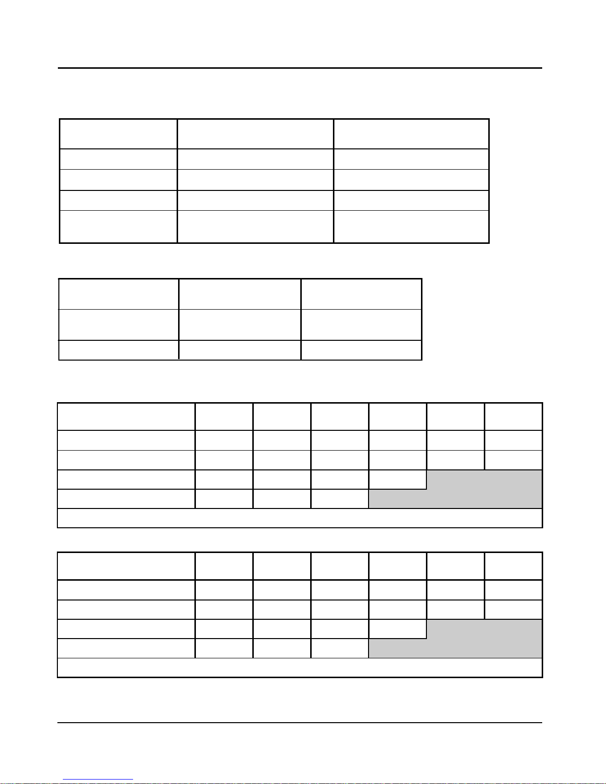
Item Description Qty. Part No.
1 Vector gate operator 1 1050M00000
2 Wall bracket (standard) 1 1050M20000
3 Wall bracket pin 1 DOMCEN0069
4 Gate Bracket 1 1050M27000
5 Gate bracket pin 1 1050M05000
6 Origin body 1 1050M0161M
7 Gate operator keys 1 GTKEYTG01
8 Gate warning decal 2 LABELGATE1
9 Cap screw M6 x 25 1 B124106025
10 14mm snap ring 1 F1400SNAPR
11 12mm snap ring 1 F1200SNAPR
12 M6 nut 1 N120206000
Figure 2 Standard P ackage C ontents
Page 9
11
1
2
3
5
4
6
8
7
10
12
9
Package Contents
Package Contents
For standard V400 and V500 operators
(VEC40000V2 & VEC50000V2)
Page 10
Page 10
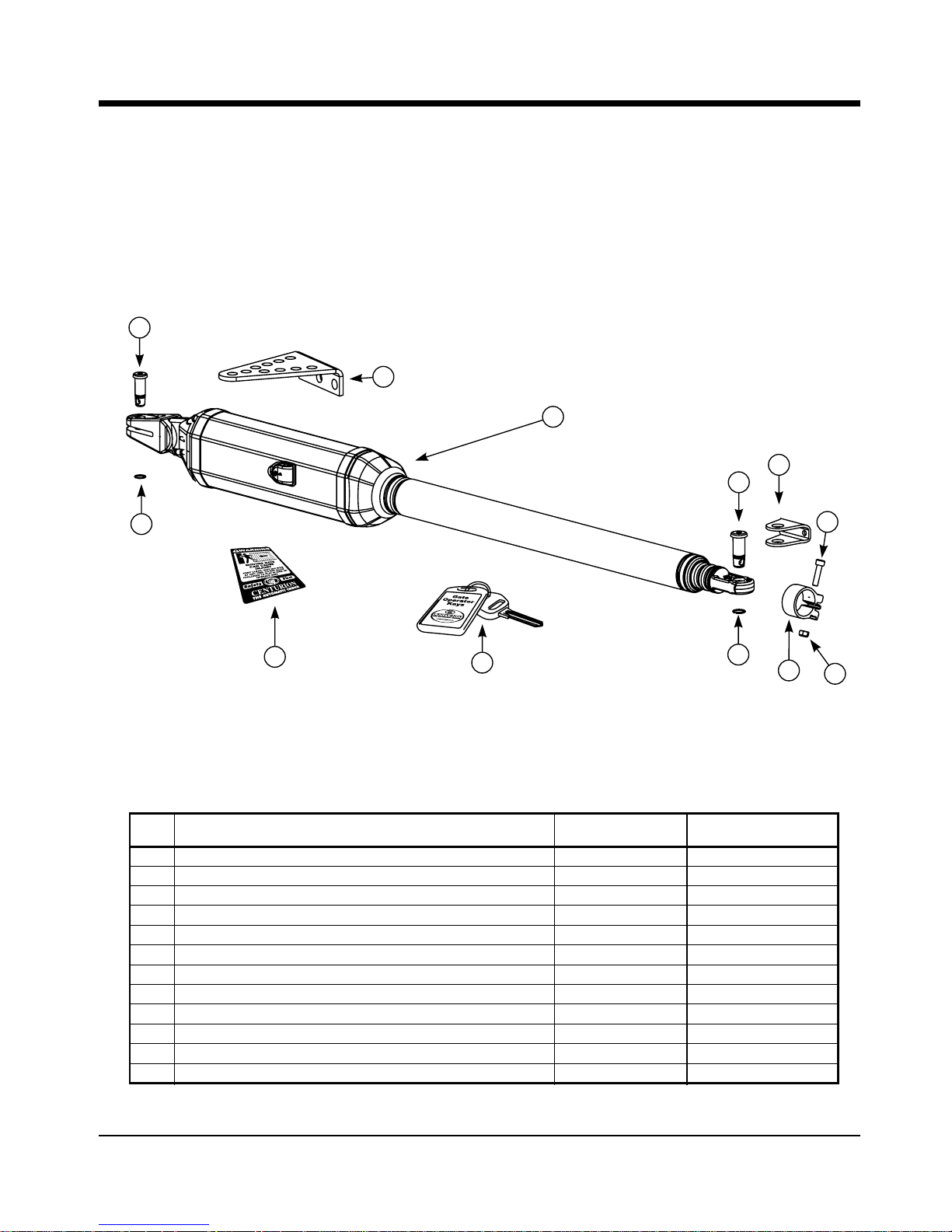
Control box including charger & controller (Domestic)
VECCAD00V2 / (Light Industrial) VECCAD01V2
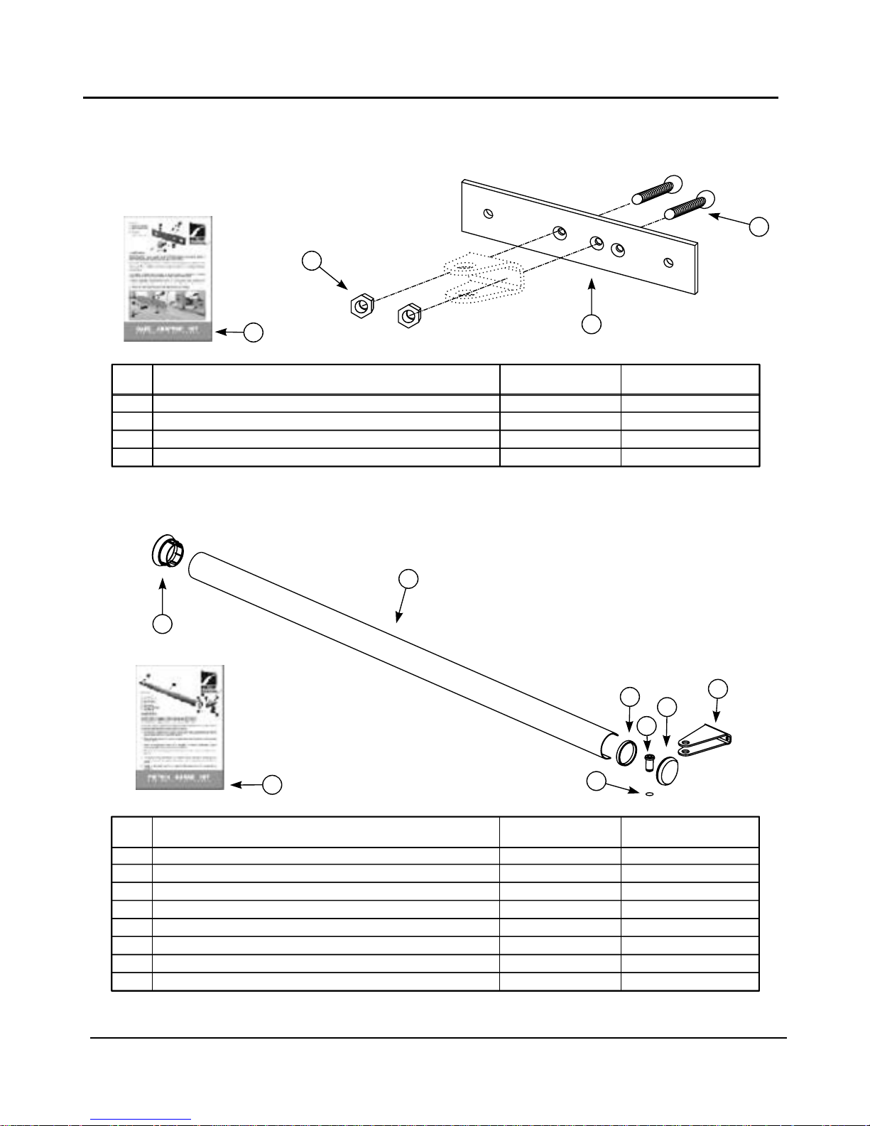
Figure 3 Optional A ccesso ries continued.
Item Description Qty. Part No.
1 Wall adaptor plate 2 1050M34000
2 M10x20 Countersunk screw 2 B123201025
3 M10 Hexnuts 2 N120110000
4 Vector wall adaptor kit packing leaflet 1 DOC1050D06
Wall adaptor kit (optional) VECWAK00V1
3
1
2
4
1
2
7
4
5
6
3
1
2
3
4
5
6
7
1
1
1
1
1
2
1
1
1
1
1
1
VECC-D00V2
CP84E V2
Misc parts
DOC1050D01
TBA
TX4NV2433
CP4C
Vector Control Card Version 2 built in Rx
CP84E Charger
Wall box
User Guide
Installation Manual
NOVA 4 button transmitters
12V 7.0AH Battery (User supplied - not part of kit)
Item
Description Qty QtyDomestic
VECC-D01V2
CP84SM2A0
Misc parts
DOC1050D01
TBA
CP4C
Light Ind
Page 11
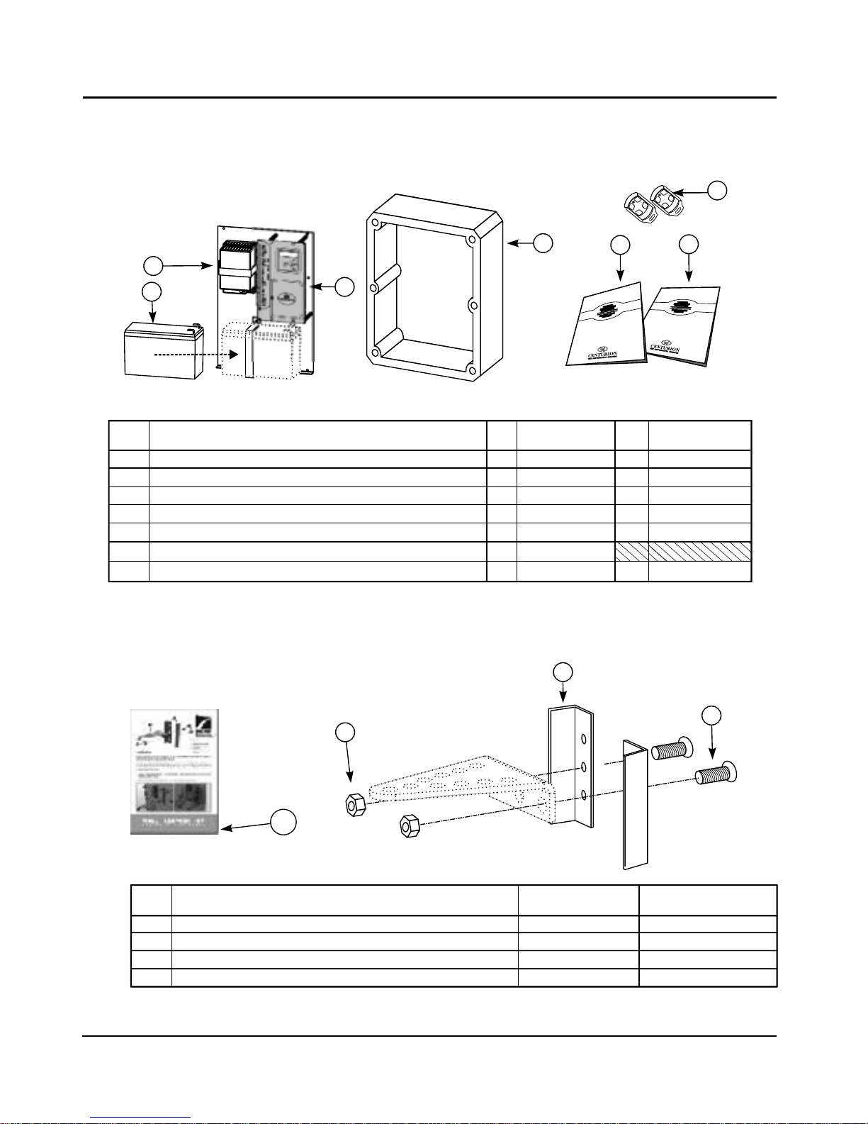
Item Description Qty. Part No.
1 Wall bracket (high security) 1 1050M3000D
2 Padlock 2 M-PLTRI263
4 Vector high security kit packing leaflet 1 DOC1050D05
High security kit (optional) VECHSK00V1
Page 11
1
2
3
Item Description Qty. Part No.
1 Vector securing plate (short) 1 1050M3200D
2 Vector securing plate (long) 1 1050M3300D
3 M10x20 Bolt 2 B121210020
4 M10 Hexnut 2 N120110000
5 Vector mechano kit packing leaflet 1 DOC1050D08
Mechano kit (optional) VECMAK00V1
1
2
3
4
5
Page 12
Page 12
Item Description Qty. Part No.
1 Gate bracket spreader plate 1 1050M03500
2 M6x12 Countersunk screw 2 B123206010
3 M6 Hexnuts 2 N1202060SS
4 Vector gate adaptor kit packing leflet 1 DOC1050D07
Gate adaptor kit (optional) VECGAK00V1
1
2
3
4
Item Description Qty. Part No.
1 Piston guard 1 1050M0321P
2 Guard retainer 1 DOMCEN0070
3 Guard sleeve 1 DOMCEN0070
4 Guard cap 1 DOMCEN0070
5 Guard pin 1 1050M35000
6 Guard gate bracket 1 1050M2400D
7 14mm snap ring 1 F1400SNAPR
8 Piston guard kit packing leaflet 1 DOC1050D04
Figure 3 Optional A ccesso ries
Piston guard kit (optional) VEC4PG00V1
1
2
3
4
5
7
6
8
Page 13
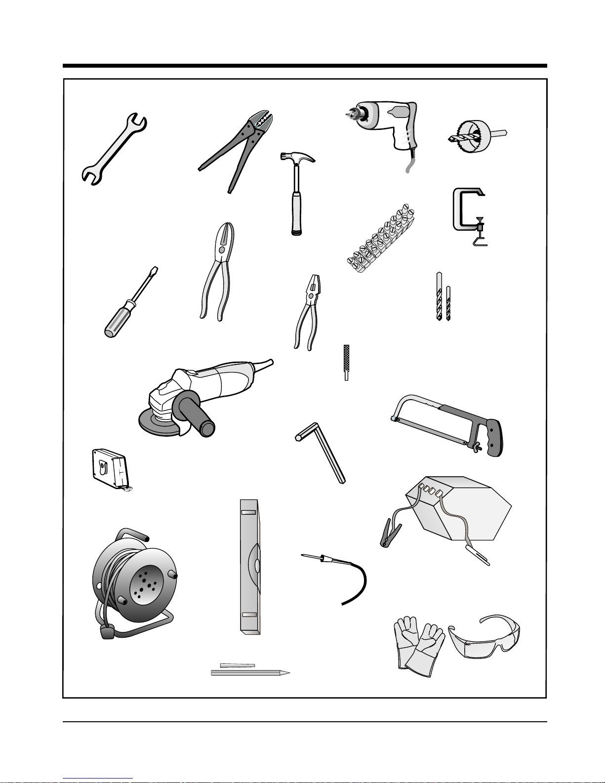
Required Tools & Equipment
Required Tools & Equipment
Figure 4 R equired Tools and E quipm ent
Spanner
17mm, 15m m
Preferably Socket Set
Screw Drivers
6mm Philips
3.5 Flat
Crimping Tool
and Pin Lugs
Pliers
Side Cutters
Hammer
2 X G-Clam ps
Electric
Drilling
M achine
M easuring Tape
H acksaw
Angle
Grinder
Spirit
Level
Marking pen/Chalk
5m m A llen Key
20mm Hole Saw
Connector block
Safety Equipm ent
G oggles, gloves, etc.
Welding M achine
(including consum ables
& safety equipm ent)
Soldering Iron
M asonry Bits - 12m m
10mm For Wall M ount Brackets
Steel Bits 6.5mm/10.5m m
6mm Pin Punch
Extension Cord
SFW
Page 13
Page 14
Site Considerations
Site Considerations
Page 14
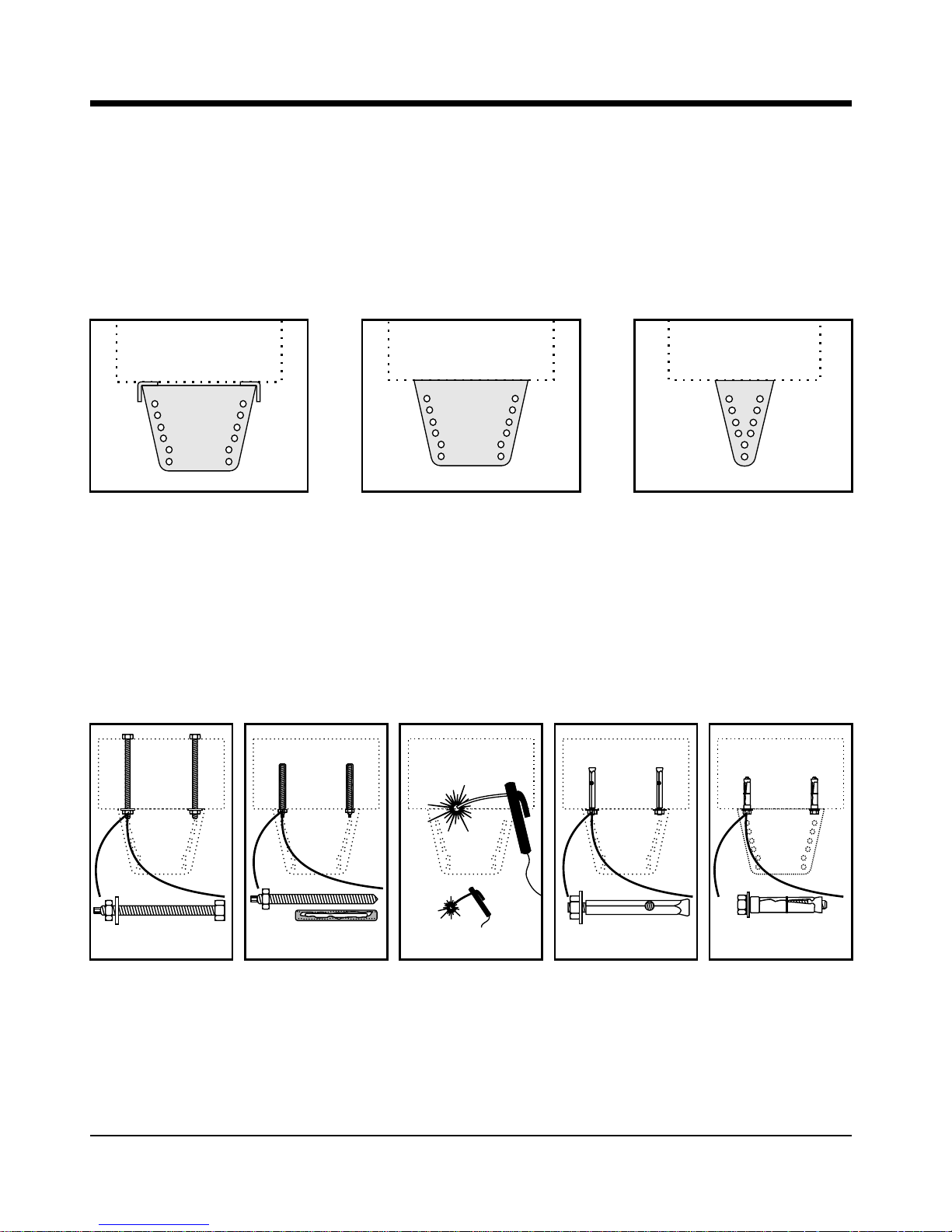
Inordertoensureareliableand durableinstallationthoughtshould begivento:
Strengthofthepillar
For reliable operation it is important to ensure that the way the operator is secured to the wall takes into
accountthestrengthofthepillar, thesizeofthegate,andhowfrequentlythe gatewouldbeused:
PILLARPILLAR
PILLAR
This mounting works well for
heavy gates shorter than
about 2m in single household domestic applications.
Alternatively it should be
considered for use on pillars
of low or unknown strength.
This mounting means is
typically used on light to
medium weight domestic
gates that are about 1.5m
long, and that is mounted on
pillars of average strength.
This mounting is highly
recommended for all light
industrial gates, or for heavy
gates of any length.
Alternatively it should be
considered for use on pillars
of low or unknown strength.
Standard bracketHigh security kit
High security kit
together with a
Wall adaptor kit
BEST WORKS WELL GOOD
Asimportantasthebracketishow thebracketissecured tothepillar:
Applications:
• Prefabricated
walling
• For heavy gates
operating
frequently
PILLAR PILLAR
STEEL
PILLAR
PILLAR PILLAR
Applications:
• Masonry pillars
• Frequent use
Applications:
• Lighter gates
• Domestic
Applications:
• Light gates
• Domestic
Applications:
• Very light
• Very domestic
Through wall
Chemical
anchors
Welding
Sleeve
anchors
RAWL Bolts
BEST WORKS WELL WORKS WELL OK
NOT
RECOMMENDED
Page 15
Page 15
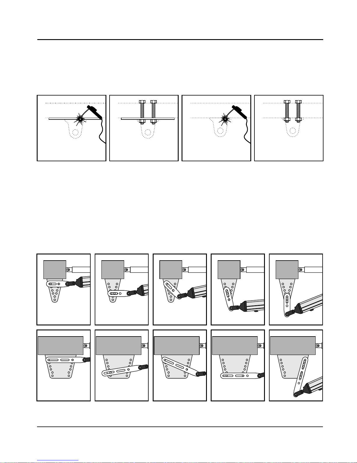
Strengthofthegateand gatebracket
The gate adaptor kit both strengthens the connection to the gate, and also allows for more flexibility when
mountingthebrackettothegate:
TheMechanokit
This kit is useful when fitting VECTORS to existing installations, and also makes adjustments easier when
doingnewinstallations.
Applications:
• Light industrial
• Heavy gates
• Frequent use
Applications:
• Domestic
• Medium gates
• Frequent use
Applications:
• Domestic
• Light gates
• Infrequent use
Welding
Gate adaptor kit
Through bolts
Gate adaptor kit
Welding
Through bolts
(High tensile)
FAIRGOODVERY GOODBEST
Tex screws and mild steel bolts are not recommended
Page 16
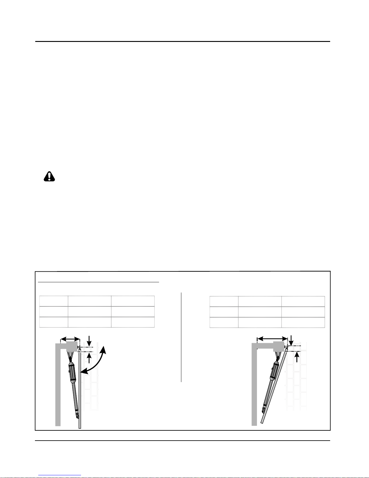
Figure 5 Minimum Installation Requirem en ts
Installthegateoperatoronlyif:
1. Itwillnotposea hazardtothe public.
2. Thereissufficientclearanceto aroadwayand/or publicthoroughfares.
3. Theinstallationwillmeetall municipaland/orlocal authorityrequirementsonce completed.
4. Thegatemass,lengthand applicationiswithin theoperatorspecifications (seepage8).
5. Thewindloadingspecificationsare notexceeded(see page42).
6. Thegateisingood workingorder,vertically hungandswings freely.
7. Itcanbeinstalledtohave sufficient clearance between moving parts whenopeningandclosingtoreducethe
riskof personalinjuryand entrapment.
8. Pushbuttons or key switches, when required, must be positioned so that the gate is in line of sight of the
operator.
Generalconsiderationsfortheinstallation:
1. Always recommend the fitment of additional safety equipment such as safety edges and safety beams, for
additionalprotection againstentrapmentor othermechanicalrisks.
2. Checkthatnopipesor electricalcablesare intheway oftheintendedinstallation.
3. Checkthatenoughspaceis availableforthe gateoperatorwith thegateintherequiredopenposition.
(Seediagram below).
4. Checkthestrengthofthe mountingpillarand fitawall adaptorkit whereneeded.
5. Iftheswinggateleaf islongerthan 2.5m,ensure thatalockcanbefitted.
6. Neverfittheoperatorontheoutsideofthegate,wherethepublichasaccesstoit. (Followtheinstructionsfor
anoutward openingswinggate, ifrequired.)
7. Forgreater securityconsiderfittinganoptionalhighsecuritykit.
8. Consider where the gate bracket will be mounted. It might simplify the installation to fit the optional gate
adaptorkit.
Page 16
There must be 2 sets of beams. One across the driveway when the gate is closed and one when the gate is open.
Gate opening
90° or less
Pillar (Max.) *
Wall (Min.) #
Wall (Min.) *
Gate opening
110°
Gate opening 90° or less
Operator
V400
150mm
150mm 250mm
V500
335mm
Wall (Min.) # Pillar (Max.)*
Gate opening 110°
Operator
V400
150mm
150mm 145mm
V500
210mm
Wall (Min.) # Pillar (Max.)*
Minimum Installation Requirements
(Tables are based on gates shorter than 2.5m.
• For gates 2.5m to 3.0m long, reduce the maximum pillar thickness by 20mm.
• For gates 3.0m to 3.5m long, reduce the maximum pillar thickness by 40mm.
• For gates 3.5m to 4.0m long, reduce the maximum pillar thickness by 60mm.)
# - The typical minimum wall clearance required to fit the operator.
* - The maximum allowable pillar thickness on which to fit the operator.
Pillar (Max.) #
Page 17
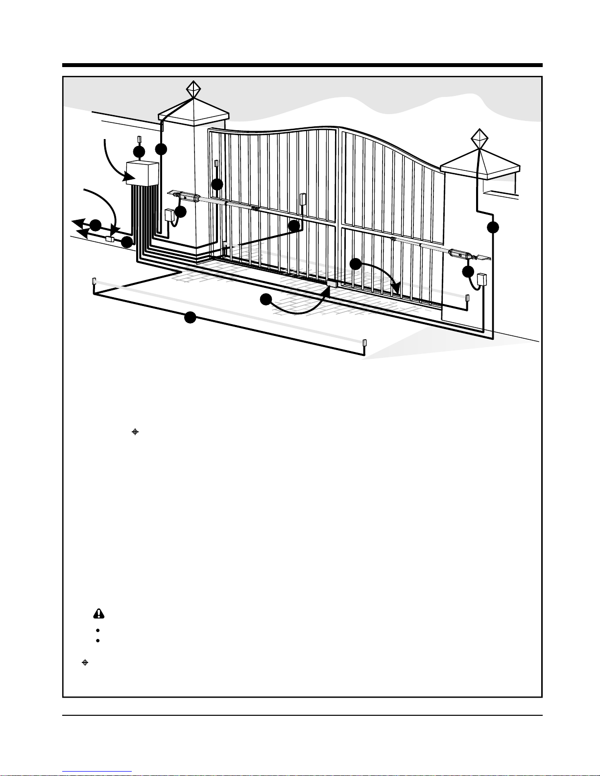
Cabling Requirements
Cabling Requirements
Figure 6 C abling Requirem en ts
Page 17
1. 220V AC mains cable via mains isolator Or
switch (3 core LNE 0,5mm²)*,
Optional keypad (if required, 3 core
2
Or
0,5mm multi-stranded).
Low voltage 16V AC battery charger
6. Optional infrared beams or safety edge
2
supply (2 core 1,5mm²).
(if required, 3 core 0,5mm multistranded or 4 core 0.5mm² for CE
2. Intercom cable (n1 + 6 core) to house.
compliance.)
3. MOTOR M (MTR M) or MOTOR S
7. Optional intercom cable (n2+2 core
(MTR S) cable (if required minimum,
0,5mm²multi-stranded) to gate station
2
2 core 2mm + 4 core 0,5mm² multistranded) ¥
8. Optional electric lock. (2 core 0.5mm²)
See page 8.
4. Optional radio receiver cable (3 core
2
0,5mm multi-stranded, optional) # 9. Optional pillar light cable (3 core, size
according to power reg.)
5. Optional pedestrian key switch (if
2
required, 2 core 0,5mm multi-stranded).
†
To dw elling
Mains
iso lator
sw itch
C ontro l
box
4
5
7
6
n1 = number of cores required by intercom. n2 = number of cores required by intercom.
2
LEGEND
1
8
9
9
3
3
6
†
Mains isolator must be fitted less than 1m from controller
* Increase cable thickness if pillar lights are to be installed.
Screened cable is always recommended to provide better protection against lightning earth one end of screening.
Domestic charger only.
# For optimum range an external receiver can be mounted on the wall.
¥ Centurion has available customer VECTOR cable order reference: CABLEVEC68
Page 18

1. Determinegate opening angle and directionof
operator(inwardoroutward).
Alternatively the swing angle can be determined more accurately with the process
detailedonpage37.
120°
100°
110°
90°
80°
70°
60°
OPEN
CLOSED
E
L
G
N
A
G
N
I
W
S
E
T
A
M
I
T
S
E
2. Determine a suitable height for the wall
bracket.
Wall Bracket
85m m
Gate Bracket
Minimum 125m m
3. Determinewhere to put the bracket according
toAandBvaluesinthetablesonpages23and
25.
B
A
120°
110°
100°
90°
80°
70°
60°
Gate opening angle
0°
120°
110°
100°
90°
80°
70°
60°
Gate opening angle
0°
For tables see page 23 or 25
.
or
or
USE MECHANO KIT CUT THE BRACKET
CAUTION:
Take care to shorten
the wall bracket to
prevent interference
with the operator
Operator Installation
Operator Installation
Page 18
The gate bracket must fit to a sturdy point on
the gate.
Consider using the optional gate adaptor kit.
OPERATOR MUST NOT FOUL AGAINST BRACKET
Page 19

4. Secure the bracket to the wall with the most
appropriate means.
See page 14 for site considerations.
5. Fitthegatebrackettotheoperator.
1 OR 2 TURNS
6. Fit the motor end of the operator to the wall
bracket.
7. Open the gate fully and temporarily clamp the
gatebrackettothegate.
Determine the gate bracket position
Page 19
The gate bracket must fit to a sturdy point on
the gate.
Consider using the optional gate adaptor kit.
Start with the operator fully retracted.
Turn out the actuator tube one or two turns.
Page 20

or
or
8. Unlock the operator and swing the gate
closed.
9. Remove the pin and the operator from the
bracket,checkthat there are at leastoneortwo
turnsof theactuatorbeforeitisfullyextended.
10. Secure the gate bracket using the most
appropriate means.
11. Fitoperator, wallbracketpinsandsnaprings.
Fasten gate bracket to gate
Page 20
See page 14 for site considerations.
If it becomes obvious that the operator does not
have enough stroke, reduce either the A or B
distances by moving the wall bracket.
Be sure not to make the A and B values less than
allowed for in the installation tables on page 23.
In general:
• Large B distances give good security and
good closing push force.
• Small A and small B will increase the speed.
or
As an alternative to the snap ring, fit a
padlock.
Page 21

or
13.Unlock the operator and open the gate fully
14. Slide the origin clamp along the actuator
tube, right up to the operator.
Secure in place with an allen key tighten
properly.
15.Attachwarningdecalstothegateasshown.
2
1
Adjust origin clamp
(NB - Not required for outward swinging gates)
Page 21
open
12. Fitoperator, gatebracketpinsandsnaprings
As an alternative to the snap ring, fit a
padlock.
The mechanical part of the installation is now complete.
Page 22

Figure 7 Position Inw ard Opening Gates
Page 22
Operator Installation
Operator Installation
B
A
Inward Swing Gate Setup
B
A
For gates opening 90° or less:
For gates opening m ore than 90°:
Ensurethatthe gate does notexceed the
gatem assspecifications on page 8.
For bestsecurity(butslow er operation)
installwithlarge B value
For fast operation (but less security)
installwithsmallA andsm allB values
GATE OPEN
GATE OPEN
GATE CLOSED
Page 23

Alternative positions
A and B must each be greater than
Gate swing A+B should Up to Up to Up to Up to Up to Up to
angle not exceed 1.5m 2m 2.5m 3m 3.5m 4m
60° - 90° or less 465mm
100° 400mm
110° 340mm
120° 285mm
Recommended positions
(Only for a 2.5m gate or shorter)
A value B value
90° or less 220 220
100° 190 190
110° 150 150
120° 135 135
Alternative positions
Gate swing A+B should Up to Up to Up to Up to Up to Up to
angle not exceed 1.5m 2m 2.5m 3m 3.5m 4m
60° - 90° or less 380mm
100° 325mm
110° 275mm
120° 230mm
A and B must each be greater than
Recommended positions
(Only for a 2.5m gate or shorter)
A value B value
90° or less 150 150
100° 155 155
110° 125 125
120° 110 110
120°
100°
110°
90°
80°
70°
60°
Gate opening angle
0°
120°
100°
110°
90°
80°
70°
60°
Gate opening angle
0°
1400mm Extended
1400mm Extended
1000mm Retracted
1000mm Retracted
1600mm Extended
1600mm Extended
1100mm Retracted
1100mm Retracted
For V400 (400mm operator)
For V500 (500mm operator)
100mm 100mm 100mm
120mm
140mm 160mm
NOT RECOMMENDED
100mm 100mm 100mm
120mm
140mm 160mm
NOT RECOMMENDED
NOTE:
100m m for A or B w ould ensure a 10mm clearance betw een the operator and gate if the gate is 50mm thick
NOTE:
100m m for A or B w ould ensure a 10mm clearance betw een the operator and gate if the gate is 50mm thick
Page 23
Gate swing
angle
Gate swing
angle
Page 24

Outward Swing Gate Setup
B
A
make up bracket
to suit
For gates opening 90° or less:
B
A
make up bracket
to suit
For gates opening m ore than 90°:
Figure 8 Position Outward Opening Gates
Page 24
Ensurethatthe gate does notexceed the
gatem assspecifications on page 8.
Outward opening swing gates m usthave
physical end stops fitted inthe open
position.
Originclam ps m ust N O T be
fitted.
For bestsecurity(butslow er operation)
installwithlarge B value
For fast operation (but less security)
installwithsmallA andsm allB values
GATE CLOSED
GATE OPEN
GATE OPEN
End stop see
Caution Note
CAUTION:
Page 25

Page 25
Alternative positions
A and B must each be greater than
Gate swing A+B should Up to Up to Up to Up to Up to Up to
angle not exceed 1.5m 2m 2.5m 3m 3.5m 4m
60° - 90° or less 465mm
100° 400mm
110° 340mm
120° 285mm
Recommended positions
(Only for a 2.5m gate or shorter)
A value B value
90° or less 220 220
100° 190 190
110° 150 150
120° 135 135
Alternative positions
Gate swing A+B should Up to Up to Up to Up to Up to Up to
angle not exceed 1.5m 2m 2.5m 3m 3.5m 4m
60° - 90° or less 380mm
100° 325mm
110° 275mm
120° 230mm
A and B must each be greater than
Recommended positions
(Only for a 2.5m gate or shorter)
A value B value
90° or less 150 150
100° 155 155
110° 125 125
120° 110 110
120°
100°
110°
90°
80°
70°
60°
Gate opening angle
0°
120°
100°
110°
90°
80°
70°
60°
Gate opening angle
0°
1400mm Extended
1400mm Extended
1000mm Retracted
1000mm Retracted
1600mm Extended
1600mm Extended
1100mm Retracted
1100mm Retracted
For V400 (400mm operator)
For V500 (500mm operator)
100mm 100mm 100mm
120mm
140mm 160mm
NOT RECOMMENDED
100mm 100mm 100mm
120mm
140mm 160mm
NOT RECOMMENDED
NOTE:
100m m for A or B w ould ensure a 10mm clearance betw een the operator and gate if the gate is 50mm thick
NOTE:
100m m for A or B w ould ensure a 10mm clearance betw een the operator and gate if the gate is 50mm thick
Gate swing
angle
Gate swing
angle
Page 26

Electrical Set-up
Electrical Set-up
WARNING
1. Alwayscheckthattheisolatorin the mains supplytothegateisinthe OFF position,beforedoingany
work.
2. Ensure that all low voltage systems (Less than 42.4V) are suitably protected from damage, by
disconnectingallsourcesof powersuchas chargersandbatteriesbeforedoing anywork.
3. Allelectricalworkmustbe carried out accordingto the requirements of all applicable local electrical
codes. (Itisrecommendedthatalicensedelectricalcontractorperformsuchwork.)
Page 26
1. Secure the control box to wall using the most
appropriatemeans.
Secure control box to wall
p 1
CONTROL BOX
PREFERABLY MOUNTED
AT EYE LEVEL
Be sure to position the wall box so as not to
cause any hazards during and after the
installation.
Preferably mount the wall box:
• Out of direct sunlight
• At a comfortable working height
• Away from garden sprinklers etc.
• To allow easy access even when the
gate is open
2. Connect all the cables as required to the
controlcard.Seepage46andpage47.
3. When wiring each operator back to the
controller housing, it is recommended to
mount a small junction box adjacent each
operator. Terminate the cable provided on the
operatorinto this junction boxand then routea
new cable from the junction box to the
controllerhousing.
Connect all wiring
For wiring diagram see page 46/47
Page 27

Page 27
Light
Light
Batt +
Batt MTR M+
MTR M MTR S+
MTR S -
Com
FRX
LIT
LED
Com
Aux 12V
Com Saf
Sol
4. Check that the charger and battery are
connectedtothecontroller.
Ensurethebatterypolarityiscorrect.
5. Switchonthemainssupply(viaisolator).
6. Ensurethat both the controller and charger are
effectively earthed for improved lightning
protection.
Settingthelimits
7. Check that the origin has been correctly set.
(Seepage 21)
open
8. Checkthatthegateis closedandtheoperatoris
locked.
9. Push and hold the SETUP button ( ) for 3
seconds. Select the “limits” menu by pressing
the ENTER button ( ). The Limit setup
wizard will now begin. Follow the on-screen
instructions to complete the setup procedure.
SSens1
SSens2
M Sens1
M Sens2
Sens+
Sens-
Safe CLS
Safe OPN
Com
LCK/STP
TRG
PED
33333
Exit Go
Up/Dn
Exit Go
Up/Dn
Exit Go
Up/Dn
Exit Go
Up/Dn
Exit Go
Up/Dn
Exit Go
Up/Dn
Exit Go
Up/Dn
Exit Go
Up/Dn
Exit Go
Up/Dn
AutoCloseAutoCloseAutoCloseAutoCloseAutoClose
Page 28

Figure 10 provides the full menu of features that can be setup on the system. Explanation of each
feature is provided in the section “CONTROLLER FEATURES”.
When setting up the VECTOR system via the LCD display, all the steps that have to be followed are
clearly provided via the display. It is only necessary to note the following:
? To get into setup mode, press the (oblong) button for 3 seconds and follow the instructions
provided from there.
? The buttons provided on the controller for navigating the system, are not marked because at each
step during the setup, the function given to each button is provided on the display.
? When not in setup mode, ie normal mode, the (round) button is used as a TEST button for
operating the system. The up/down buttons are not used unless the diagnostic screens have been
selected to appear in normal mode, in which case these buttons allow switching from one screen
to the next.
For each feature, a factory default setting has been programmed into the controller. The defaults have
been determined to suit a typical domestic swing gate installation. It is only necessary to change a
feature where the default does not suit the installation being carried out. When selecting any feature in
the menu, details of the current setting stored in the controller are displayed.
Page 28
Figure 9 View of C ontroller
S Sens1
S Sens2
M Sens1
M Sens2
Sens+
Sens-
Safe CLS
Safe OPN
Com
LCK/STP
TRG
PED
Com
FRX
33333
Exit Go
Up/Dn
Exit Go
Up/Dn
Exit Go
Up/Dn
Exit Go
Up/Dn
Exit Go
Up/Dn
Exit Go
Up/Dn
Exit Go
Up/Dn
Exit Go
Up/Dn
Exit Go
Up/Dn
AutoCloseAutoCloseAutoCloseAutoCloseAutoClose
Menu Level
Menu Level
How to set up additional features
on the Vector Controller
How to set up additional features
on the Vector Controller
Page 29

Menu Navigation Map
Menu Navigation Map
Page 29
Figure 10 Part A of “M enu Navigation M ap”
SETTING LIMITS: 1
SAFETY: 2
AUTOCLOSE: 3
MODES OF OPERATION: 4
RUN PROFILE: 5
IR BEAMS: 6
Setup Wizard
MTRM Collision Force: 2.1
MTRS Collision Force: 2.2
Collision Count: 2.3
Autoclose Status: 3.1
Autoclose Time: 3.2
Autoclose Override Time: 3.3
Autoclose Advanced Options: 3.4
Operating Mode
Positive Close: 5.1
Leaf Delay: 5.2
Pre-Open Delay: 5.3
Pre-Close Delay: 5.4
Opening Speed: 5.5
Closing Speed: 5.6
Ramp up Distance: 5.7
Ramp down Distance: 5.8
Crawl Distance: 5.9
Torque Limit: 5.10
MTRM Opening Collision Force
MTRM Closing Collision Force
MTRS Opening Collision Force
MTRS Closing Collision Force
Autoclose on Open: 3.4.1
Autoclose on Partly Open: 3.4.2
Autoclose on Partly Closed: 3.4.3
Standard Mode
Condominium Mode
Reversing Mode
Positive Close Status: 5.1.1
Positive Close Type: 5.1.2
Positive Close Short Stop Value: 5.1.3
Positive Close Push Force: 5.1.4
Leaf Delay Status: 5.2.1
Leaf Delay Value: 5.2.2
Short Stop
MTRM Only
MTRS Only
MTRM & MTRS
PIRAC Control: 6.1
SAF Output Status: 6.2
IRBO = IRBC
IR Beam Alarms: 6.3
PIRAC Status: 6.1.1
Stop On Open: 6.1.2
Ambush Alarm: 6.3.1
Break in Alarm Status: 6.3.2
Stop On Open Status: 6.1.2.1
Stop Distance: 6.1.2.2
Ambush Alarm Status: 6.3.1.1
IRB Broken time: 6.3.1.2
Page 30

Page 30
Figure 10 Part B of “M enu Navigation M ap”
Pedestrian Open Position: 7.1
Pedestrian Autoclose Time: 7.2
Pedestrian Pre-Open Delay: 7.3
Pedestrian Pre-Close Delay: 7.4
Lock Enabled Status: 8.1
Lock Type: 8.2
Release Time: 8.3
Pre-Release Time: 8.4
Lock Location: 8.5
Lock Drive (AC/DC): 8.6
Courtesy Light Time: 9.1
Light Profile: 9.2
Operating Standard: 10.1
Reset Options: 10.2
Diagnostic Screen Status: 10.3
Test Button Disabled Status: 10.4
Press Master Button
If m enu locke d
ADD Remotes: 11.1
DELETE Remotes: 11.2
EDIT Remotes: 11.3
Remotes Menu Locked Status: 11.4
Courtesy Light
Pre Flash A
Pre Flash B
Pre Flash C
Factory Default: 10.2.1
Delete All Remotes: 10.2.2
Reset All: 10.2.3
Delete Remote By ID: 11.2.1
Delete Remote Button: 11.2.2
Delete Remote By Button: 11.2.3
Delete All Remotes: 11.2.4
PEDESTRIAN: 7
GATE LOCK: 8
COURTESY LIGHT: 9
GENERAL: 10
REMOTES: 11
§ Refer to Table 1 on page 39 for Schedule of Factory Defaults for each feature.
Page 31

Page 31
§ Refer to Table 1 on page 39 for Schedule of Factory Defaults for each feature described below.
Controller Features
Controller Features
SAFETY (COLLISION FORCE) - MENU 2
MTRM/S COLLISION FORCE
If the gate is obstructed, the internal collision circuitry will activate. The response of the
system to a collision will vary, depending on the Operating Standard (eg CE, UL325)
selected. Responses can vary from one or both gates stopping, to one or both gates
reversing. The collision force can be set from Min to Max in 5 discrete steps.
A sixth step will disable collision sensing entirely, allowing MAXIMUM force to be
achieved. Under this condition, the motors will continue running until they stall, at which
point a collision will be detected. NB:This level should only be used if additional safety
measures are taken. (e.g.: Infrared beams, sensitive edge etc.)
Collision force can be set independently per motor, as well as per direction of travel.
COLLISION COUNT
A counter monitors the number of collisions that the gate experiences before both gates
reach the fully closed position. If the value exceeds the value set in the MULTIPLE
COLLISION COUNTER the controller shuts down until the next valid trigger is received.
As indication, the STATUS LED will flash 4 times every second. The multiple collision fault
indication will continue to flash indefinitely or until a valid trigger has been received.
AUTO-CLOSE – MENU 3
AUTO-CLOSE STATUS
The Auto-close feature when turned on, has the function of automatically closing the gate
after a preset auto-close time. The AUTO-CLOSE feature is automatically turned on when
the controller is set for CONDOMINIUM mode of operation.
AUTO-CLOSE TIME
The auto-close time can be set anywhere from 1 to 255 seconds.
AUTO-CLOSE OVERRIDE
It is possible for the user to temporarily turn off auto-close when the mode of operation is
STANDARD or REVERSING. To activate AUTO-CLOSE OVERRIDE, the TRG input must
be activated and maintained for a period longer than the time set for the AUTO-CLOSE
OVERRIDE TIME, after which the input can be cleared ie press and hold the button of
the remote that operates the gate.
The gate response will be to start opening on the first TRG trigger, and then to stop as
soon as the AUTO-CLOSE OVERRIDE feature is activated. On clearing of the TRG input,
the gate will continue opening until fully open. The AUTO-CLOSE feature is now off and
the gate will remain open indefinitely.
The next signal received on TRG will clear the AUTO-CLOSE OVERRIDE feature, close
the gate, and set the AUTO-CLOSE feature back to normal.
AUTO-CLOSE ADVANCED OPTIONS
The conditions under which the gate will auto close can be set within the Advanced
Autoclose options menu.
1
2
Page 32

Page 32
3
4
Page 33

If “Short Stop” is correctly set, PCM will cut off
when gates reach closed position, in line
Line of gates when closed
M gate closes
slightly behind
S Gate (Leaf delay)
S Gate closes first
Mechanical lip
1
*
M Gate continues to close
“Short Stop”
S Gate stops slightly before closed position
2
*
*
Mechanical lip on
M Gate engages with S Gate
With PCM, M Gate continues closing,
pushing the S Gate with it
3
4
Page 33
Page 34

Page 34
5
Inside
closing beam
O utside
closing beam
TYPIC A L C LO SIN G B EAM INSTALLATIO N
G ates w ill not close
Page 35

Page 35
Outside closing beam
Inside closing beam
Opening beam
IRBO = IRBC
(Combine inside closing beam with opening beam = save on one beam )
Intruder breaks beam while loitering at gate
==
Alarm
Adjustable
beam broken time
==
Alarm
++
Intruder blocks
beam
Page 36

Page 36
7
8
6
Page 37

Page 37
9
Page 38

Page 38
10
Page 39

Factory Defaults Schedule
Factory Defaults Schedule
Page 39
Table 1 Factory Defaults Schedule
PARAMETER DESCRIPTION
UNIT
MIN
DEFAULT
MAX
South African Standard Profile
Auto-Close Enabled
Auto-Close Time
Mode of Operation
Motor M Opening Force
PCM Enabled
Leaf Delay Enabled
Motor M Closing Force
PCM Type
Leaf Delay
Motor S Opening Force
PCM Stop Short Distance
Motor S Closing Force
PCM Force
Max. No. Collisions
Collision Alarm Output
Auto-Close Override Time
Auto-Close from Fully Open
Auto-Close from Partly Open
Auto-Close from Partly Closed
YES/NO
mm:ss
S,R,C
Level
YES/NO
YES/NO
Level
M,S,M & S,SS
mm
Level
mm
Level
% (A)
Collisions
B,C,P,S,L
s
00:00*
1
NO
NO
1
1
1
1
1
3*
0
1
Max (6)
YES
YES
Max (6)
Max (6)
40
Max (6)
15
255
2*
0:15
Standard
3
NO
NO
3
Master Only
10*
250*
3
5
3
3
4
Buzzer
3
04:00*
15*
NO
NO
YES
YES
YES/NO
YES/NO
YES/NO
* -Settings are fixed across standards
** -Settings are not configurable via the GUI
Table continue on next page.
Opening Speed
Closing Speed
Ramp Up Distance
Ramp Down Distance
Crawl Distance
Torque Limit
mm/s
mm
(A)
10
10
20
20
5
4
Max
Max
400
400
400
15
30
30
30
30
10
11
mm/s
mm
mm
Pre-Close Delay Time
Pre-Open Delay Time
s
s
00
0
196
196
Page 40

Page 40
PARAMETER DESCRIPTION
UNIT
MIN
DEFAULT
MAX
PED Open Distance
Gate Lock Enabled
PIRAC Enabled
IRB Ambush Alarm Enabled
IRBO Starts Wire-Less**
Courtesy Light Time
Diagnostic Screen Enabled
Remote Menu Locked
Gate Lock Type
SAF Common Enabled
IRB Ambush Alarm Hold-Off Time
IRBC Starts Wire-Less**
Courtesy Light Profile
Test Push-Button Enabled
Helix Mode Disabled**
Gate Lock Pre-Release Time
SAF Common Tests which Beams
IRB Break-In Alarm Enabled
LCK Starts Wire-Less**
Gate Lock Release Time
IRBO acts as IRBC
IRB Alarms Output
Gate Lock Location
Gate Lock Drive Type
PED Auto-Close Time
PED Pre-Open Delay Time
PED Pre-Close Delay Time
% (Full Open)
YES/NO
YES/NO
YES/NO
YES/NO
YES/NO
Minutes
YES/NO
YES/NO
B,C,P,S,L
h:mm:ss
YES/NO
YES/NO
M,S
Crt,A,B,C
YES/NO
YES/NO
s
s
C,O,C & O
C,O,C & O
YES/NO
YES/NO
AC,DC
NO
NO
NO
1
0:00:04*
NO
NO
24.0*
YES
YES
YES
255
YES
YES
9:59:59*
24.0*
NO
NO
YES
YES
0:02:00
NO
NO
Striker
NO
1
YES
Courtesy
YES
YES
0.0
IRBC Only
NO
YES
1.0
0.1*
0.1*
NO
BUZZER
Close Only
AC
30
100
240
240
240
10
0
0
0
0
2
5
s
s
s
* -Settings are fixed across standards
** -Settings are not configurable via the GUI
South African Standard Profile Continue
Table 1 Factory Defaults Schedule
Page 41

Page 41
Description of Terminal Functions
Description of Terminal Functions
Page 42

Page 42
Page 43

Page 43
LED Indicator Lights
LED Indicator Lights
The controller is fitted with diagnostic lights (LEDs) that assist with the set-up and maintenance of the gate.
Table 2providesa descriptionandpurpose oftheindicator lights.Referto figure11below forlocation.
During Normal Operation
ON
OFF
SLOW REGULAR FLASH = Gate is opening
FAST REGULAR FLASH = Gate is closing
1 FLASH EVERY 2 SECONDS = Courtesy light latched on
2 FLASHES EVERY 2 SECONDS = Mains failure
3 FLASHES EVERY 2 SECONDS = Battery low
4 FLASHES EVERY 2 SECONDS = Collision shutdown
ON
OFF
ON
OFF
ON
OFF
ON
OFF
ON
OFF
ON
OFF
ON
OFF
NAME STATUS
S Sens2
M Sens1
M Sens2
Light
Light
Batt +
Batt -
Sens+
Sens-
Safe CLS
Safe OPN
Com
LCK/STP
TRG
PED
Com
FRX
LIT
LED
Com
Aux 12V
Safe Com
Sol
Table 2 D escription of LED indicators
Figure 11 LED positions
= Gate open
= Gate closed
= Signal present
= No signal
= Opening Safeties clear
= Opening Safeties obstructed
= Closing Safeties clear
= Closing Safeties obstructed
= Signal present
= No signal
= Signal present
= No signal
= System ready to operate
= System locked
= Signal present
= No signal
STATUS
LED
TRG
Saf OPE
Saf CLO
FRX
PED
LCK/STP
LIT
Buzzer Feedback
The VECTOR 2 controller is equipped with an onboard buzzer which is used for various features and
functions on the controller. One of the functions it provides is audible diagnostic feedback as detailed
in the table below:
Multiple collision condition
Battery low condition
Holiday lock-out enabled
Buzzer emits a pulsed tone for a 5 second duration,
after the controller is activated in a battery low
condition.
Buzzer emits a continuous pulsed tone as soon as
a multiple collision shutdown is activated. The tone
will cease as soon as a valid trigger input is activated.
Buzzer emits a pulsed tone for a 5 second duration
when the controller is activated with this feature
enabled.
PARAMETER DESCRIPTION
Page 44

Charger and Pillar Light Connections
Charger and Pillar Light Connections
Page 44
Thefollowingprotectionfusesareprovidedonthesystem:
Fuse Protection
Item
MAIN CONTROLLER
Motor Circuit - fuse per channel
Light circuit
Auxiliary supply
CHARGER
Mains input
Type
Automotive Fuse (25X7)
5X20mm
Electronic fuse - not replaceable
5X20mm
Rating
15A
3A Fast Blow
3A
250mA Fast Blow
S Sens1
S Sens2
MSens1
MSens2
Light
Light
Batt +
Batt MTR M+
MTR M MTR S+
MTR S -
Sens+
Sens-
Safe CLS
Safe OPN
Com
LCK/STP
TRG
PED
Com
FRX
LIT
LED
Com
Aux 12V
Safe Com
Sol
220V AC
Mains in
E
N
L
L
Protection fuse on
mains input to
charger (rating:
250mA slow blow)
Auxiliary supply
Pillar
light
NEUTRAL
LIVE
N
N
L
L
E
E
N
N
L
L
E
E
N
N
L
L
E
E
N
N
L
L
E
E
N
N
L
L
E
E
N
N
L
L
E
E
N
N
L
L
E
E
N
N
L
L
E
E
N
N
L
L
E
E
N
N
L
L
E
E
N
N
L
L
E
E
N
N
L
L
E
E
N
N
L
L
E
E
N
N
L
L
E
E
N
N
L
L
E
E
Figure 12 C harger and pillar light connections
Page 45

Usethisproceduretoaccuratelydeterminethegateopeningangle:
Determine Gate Swing Angle
Determine Gate Swing Angle
USE GATE SW ING ANGLE OF
90 Degrees
100 Degrees
110 Degrees
120 Degrees
60 Degrees
70 Degrees
80 Degrees
1 351mm
1 474mm
1 587mm
1 687mm
1 000mm
VALUE Z FRO M ...
1 075mm
1 218mm
1 587mm
1 687mm
1 732mm
1 075mm
...TO
1 218mm
1 351mm
1 475mm
Step 3
1m
Open the gate and measure a
distance along the gate a
distance of 1m from the
centreline of the gate hinge.
Make a mark on the ground.
Measure the distance on the
ground between the two marks
(Z). Using this Z value, read off
the gate opening angle from the
table below.
Step 2
1m
Close the gate and measure a distance
of 1m from the centreline of the gate hinge.
Make a mark on the ground.
Step 1
Page 45
Page 46

Figure 13 Wiring Diagram for Motor M
MASTER
SLAVE
BLACK
BLACK
RED
RED
BLUE
BLUE
PURPLE
PURPLE
BLACK
BLACK
RED
RED
BLUE
BLUE
PURPLE
PURPLE
S Sens1
S Sens2
M Sens1
M Sens2
Light
Light
Batt +
Batt MTR M+
MTR M MTR S+
MTR S -
Sens+
Sens-
Safe CLS
Safe OPN
Com
LCK/STP
TRG
PED
Com
FRX
LIT
LED
Com
Aux 12V
Safe Com
Sol
THIN PURPLE
THIN RED / GREY
THICK BLUE
THICK BLACK
THIN BLUE / ORANGE
THIN BLACK
MOTOR M (MTR M)
MOTOR M (MTR M)
Page 46
Wiring Diagram for MOTOR M
(MTR M) Operator
Wiring Diagram for MOTOR M
(MTR M) Operator
Page 47

Figure 14 Wiring Diagram for Motor S
15
15
15
15
S Sens1
S Sens2
MSens1
M Sense2
Sens+
Sens-
Saf CLO
Saf OPE
Com
LCK/STP
TRG
PED
Com
FRX
LIT
LED
Com
Aux 12V
Com Saf
Sol
Light
Light
Batt +
Bat -
MTR M+
MTR —
MTR S+
MTR S-
BLACK
BLACK
RED
RED
BLUE
BLUE
PURPLE
PURPLE
PURPLE
PURPLE
BLUE
BLUE
S Sens1
S Sens2
M Sens1
M Sens2
Light
Light
Batt +
Batt MTR M+
MTRMMTR S+
MTRS-
Sens+
Sens-
Safe CLS
Safe OPN
Com
LCK/STP
TRG
PED
Com
FRX
LIT
LED
Com
Aux 12V
Safe Com
Sol
THIN PURPLE
THIN RED / GREY
THICK BLUE
THICK BLACK
THIN BLUE / ORANGE
THIN BLACK
MOTOR S (MTR S)
MOTOR S (MTR S)
Page 47
Wiring Diagram for MOTOR S
(MTR S) Operator
Wiring Diagram for MOTOR S
(MTR S) Operator
Page 48

COM
NC
NO
O PEN ING
BEA M
+12V/24V
COM
NC
NO
IRB RECEIVER
- 12V/24V
12V or 24V
IRB Tx
CLO SIN G
BEA M
+12V/24V
IRB RECEIVER
- 12V/24V
12V or 24V
IRB Tx
Wiring Diagram for Safety Beams
Wiring Diagram for Safety Beams
(for CE compliance)
(for CE compliance)
Page 48
Page 49

Page 49
S Sens1
S Sens2
M Sens1
M Sens2
Light
Light
Batt +
Batt MTR M+
MTR M MTR S+
MTR S -
Sens+
Sens-
Safe CLS
Safe OPN
Com
LCK/STP
TRG
PED
Com
FRX
LIT
LED
Com
Aux 12V
Safe Com
Sol
Page 50

Wiring diagram for other inputs
Wiring diagram for other inputs
NEG
+12V/24V
COM
NC
NO
RADIO RECEIVER
REMOTE CONTROL CIRCUITRY
NEG
+12V
COM
NC
NO
LOOP
LOOP DETECTOR
FREE EXIT CIRCUITRY
HOLIDAY LOCKOUT
KEYSWITCH
(normally CLOSED)
PILLAR LIGHT
PUSHBUTTON
(normally OPEN)
PEDESTRIAN
KEYSWITCH
(normally OPEN)
SOLENOID
LED
STATUS
LED
Page 50
*
*
Only applicable if external radio receiver is being used
Page 51

Page 51
SOLENOID
OR STRIKE
LOCK
S Sens1
S Sens2
M Sens1
M Sens2
Light
Light
Batt +
Batt MTR M+
MTR M MTR S+
MTR S -
Sens+
Sens-
Safe CLS
Safe OPN
Com
LCK/STP
TRG
PED
Com
FRX
LIT
LED
Com
Aux 12V
Safe Com
Sol
Page 52

Page 52
Wind speeds for which operator will still operate the gate (for V400 or V500 operators)
For a 25% covered gate: (Palisades, etc.) x 1.8m high
Value of Gate lengths:
A or B dimension Up to Up to Up to Up to Up to Up to
once installed. #1 1.5m 2m 2.5m 3m(#2) 3.5m(#2) 4m(#2)
100mm 94km/h 66km/h 48km/h 44km/h 41km/h 37km/h
140mm 119km/h 85km/h 65km/h 57km/h 51km/h 46km/h
180mm 138km/h 101km/h 78km/h 67km/h 60km/h 53km/h
220mm 156km/h 114km/h 89km/h 76km/h 67km/h 60km/h
260mm 171km/h 126km/h 99km/h 84km/h 74km/h 65km/h
300mm 186km/h 137km/h 108km/h 91km/h 80km/h 71km/h
340mm 199km/h 147km/h 116km/h 98km/h 86km/h 76km/h
(#1 See page 18 or 20 for installation details) (#2 - an electric lock must be fitted)
Wind speeds for which operator will still operate the gate (for V400 or V500 operators)
For a 100% covered gate: (Fully clad gates, etc.) x 1.8m high
Value of Gate lengths:
A or B dimension Up to Up to Up to Up to Up to Up to
once installed. #1 1.5m 2m 2.5m 3m(#2) 3.5m(#2) 4m(#2)
100mm 47km/h 33km/h 24km/h 22km/h 20km/h 19km/h
140mm 59km/h 43km/h 32km/h 28km/h 26km/h 23km/h
180mm 69km/h 50km/h 39km/h 34km/h 30km/h 27km/h
220mm 78km/h 57km/h 44km/h 38km/h 34km/h 30km/h
260mm 86km/h 63km/h 49km/h 42km/h 37km/h 33km/h
300mm 93km/h 68km/h 54km/h 46km/h 40km/h 35km/h
340mm 100km/h 74km/h 58km/h 49km/h 43km/h 38km/h
(#1 See page 18 or 20 for installation details) (#2 - an electric lock must be fitted)
Allowable Wind Loading
Allowable Wind Loading
Page 53

Page 53
Installation Handover
Installation Handover
Once the installation has been successfully completed and tested, it is important for the installer to
explaintheoperation and safetyrequirementsofthesystem.
NEVERASSUMETHEUSERKNOWS HOW TO SAFELYOPERATEANAUTOMATEDGATE.Evenifthe
user has used one before, it does not mean he knows how to SAFELY operate it. Make sure that the user
fullyunderstandsthefollowingsafetyrequirementsbefore finallyhandingoverthe site.
Ensurethattheuserfullyunderstands:
!
Howtooperatethemanualreleasemechanism. (Bydemonstration)
!
Howtheobstructiondetectionandallothersafetyfeatureswork. (Bydemonstration)
!
All the safety considerations associated with operating an automated gate, and that he
understands that he is responsible for explaining these safety instructions to all other users of
theautomatedsystem:
1. Do not activate your gate operator unless you can see it and can determine that its area of
travelisclearofpeoplepets,orotherobstructions.
2. NO ONE MAY CROSS THE PATH OF A MOVING GATE. Always keep people and objects
awayfromthegateanditsarea oftravel.
3. NEVER LET CHILDREN OPERATE OR PLAY WITH THE GATE CONTROLS, and do not
allowchildrenorpetsnearthegate area.
4. Be careful with moving partsandavoidcloseproximity to areas where fingers or handscould
bepinched.
5. Secure all easilyaccessed gate operator controls in order toprevent unauthorized use of the
gate.
6. Keep the automated gate system properly maintained, and ensure that all working areas are
freeofdebrisandotherobjectsthatcouldaffectthegate operationandsafety.
7. On a monthly basis, check the obstruction detection system and safety devices for correct
operation.
8. Allrepairandservice worktothisproduct mustbedonebyasuitablyqualifiedperson.
9. This product was designed and builtstrictly for theuse indicated in this documentation. Any
other use, not expressly indicated here, could compromise the good condition/operation of
theproductand/orbeasourceof danger.
10.Centurion Systems (Pty) Ltd does not accept any liability caused by improper use, of the
product,orforuseotherthanthat forwhichtheautomated systemwasdesigned.
11.Ensure that the customer is in possession of the User Guide and also complete the installationdetailsinthebackofthe UserGuide.
Page 54

Sharecall 0860-CENTURION
(Sharecall number applicable when dialed from within South Africa only)
(Omit (0) when dialing from outside South Africa)
or visit www.centsys.co.za
for details of your nearest agent
For technical support, contact:
South A frican B ranches and Regional D istributors:
O ther C ountries:
Johannesburg Central/West Rand.........................................011-699-2400
Johannesburg East-Rand ...............................................011-397-6401
Durban.............................................................. 031-701-9583
Nelspruit ........................................................... 013-752-8074/5
Pretoria..............................................................012-349-1745
Cape Town ...........................................................021-552-9425
Port Elizabeth .......................................................041-581-6994/5
East London ..........................................................043-743-4923
Bloemfontein .........................................................051-448-1714
Kimberly.............................................................053-832-3231
Vereeniging ..........................................................016-422-5667
Please refer to our website: www.centsys.co.za
Centurion Systems (Pty) Ltd Head Office:
Tel: +27 (0)11-699-2400, Fax: +27 (0)11-704-3412 or (0)11-462-6669
148 Epsom Avenue, North Riding
P.O. Box 506, Cramerview, 2060
South Africa
Latest Revision: 10.10.2008
Docum ent Ref.: 1050.D .01.0009_14
M aster address page: 0000.D.01.0004_5
© 2007 Centurion System s (Pty) Ltd.
Product C ode: DO C 1050D01
Product C ode: DC P70R 507
 Loading...