

Page 1
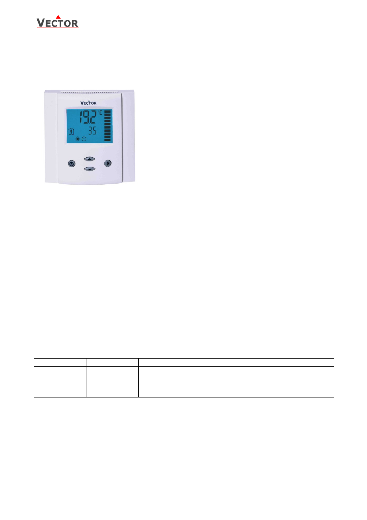
TLC-FCR-2 Intelligent Fan Coil controller
Features
Deluxe Version:
TLC-FCR-2 Engineering Manual
• Low power energy consumption: < 1W per unit
• Relays switching for outputs each up to 300W
• Temperature control for 2 or 4-pipe fan coil systems.
• Large temperature range from –40°C to 70°C (-40°F to 158°F).
• Choose between one 3-point actuator and two binary
heating/cooling stages
• Automatic fan control for three stage fans.
• Cost saving option with Economy functionality and set point
limitations
• Control for single stage heating, cooling and fan only operation
modes
• Password protected programmable user and control parameters
o Setpoint range limitation
o Access control for setpoints, fan speeds and mode
change
o Access control for heat/cool change and time programs
o Select your display contents
o Selectable behavior after return from power failure
• Temperature display in Celsius or Fahrenheit
• Clock and time schedule functions
• Blue backlight for LCD
• Infrared remote controller option:
With special features for Boost and delayed switching on or off
Applications
• Air Only Systems:
o Constant Air Volume systems with thr ee stage fans for single or dual duct systems
• Air/Water Systems:
o Fan Coil units for 2-pipe or 4-pipe systems
o radiator control, chilled ceiling
• Simple individual room control for hotel rooms, meeting rooms, etc.
General Description
The TLC-FCR-2 is a stand-alone electronic fan coil controller with one control loop. The TLC-FCR-2 features 1 NTC
temperature sensor input and four binary outputs (Relays).
A detailed parameterization is possible with the use of a simple configuration routine. The TLC-FCR-2 can be
configured using the standard operation terminal. No special tools or software is required.
Ordering
Item Name Item code Variant Features
TLC-FCR-2
TLC-FCR-2-W01
TLC-FCR-2-D
TLC-FCR-2-D-W01
40-10 0017
40-10 0017-01
40-10 0018
40-10 0018-01
Standard
Cooling only
Deluxe
Cooling only
Fan coil controller with:
1 TI int
3 DO (Relay) Fan control
2 DO (Relay) Binary valve control
Selection of valve actuators and fans
Binary auxiliary devices: E.g. fans, on/off valves, etc. Do not directly connect devices that exceed 2(1.2)A. Observe
startup current on inductive loads! Do not connect more than one fan coil unit to one controller.
Doc: 70-00-0081, Date: 20081219 © 2008 Vector Controls Ltd. Page 1
Page 2
TLC-FCR-2 Engineering Manual
Technical Specification
Power Supply Operating Voltage 210 – 240 V AC 50/60 Hz
Power Consumption Max 1W, 1.5 VA
Electrical Connection Terminal Connectors
Deluxe type only:
Signal Inputs Temperature Inputs
Signal Outputs Digital Switching Outputs
Environment Operation
Transport & Storage
Standards
General Dimensions (H x W x D) Front part: 21 x 88 x 88mm (0.8 x 3.5 x 3.5 in.)
Weight (including package) 260g
Power backup for real time clock
Range
Resolution
Accuracy
Switching type
AC Switching power
Climatic Conditions
Temperature
Humidity
Climatic Conditions
Temperature
Humidity
Mechanical Conditions
conform according to
EMC Standard 89/336/EEC
EMEI Standard 73/23/EEC
Product standards
Automatic electrical controls for
household and similar use
Special requirement on
temperature dependent controls
Degree of Protection IP30 to EN 60 529
Safety Class II (IEC 60536)
Mechanical Design and Installation
The unit consists of three parts:
1. The mounting plate made of galvanized steel.
2. The power case made of fire proof ABS plastic.
3. The front part made of white fire proof ABS plastic.
Installation
1. Arrange the wires to be connected and cut them to equal length.
2. Connect them to the terminals of th e power case according to wiring diagram
3. Clip the power case to the mounting plat e, pull the connection cable through the large central opening of the
mounting plate. Insert the power case into the flush mounting box. Carefully arrange power wires.
4. Install the mounting plate to the flush mounting box. Make sure that the nipple with the front holding screw is
facing to the ground. Make sure the screw heads do not stand out more than 5 mm of the surface of the
mounting plate.
5. Connect the connection cable to the plug located on the back of the front part.
6. Slide the two latches located on the to p of the front part into the hooks of the mounting plate.
7. Lower the front part until located flat on the wall and the mounting plate is not visible anymore. Make sure
the connection cable does not get into the way.
8. Tighten the front holding screw to secure the front par t to the mounting plate.
Mounting location
• On an easy accessible interior wall, approx. 1.5 m above the floor in an area of average temperature.
• Avoid direct sunlight or other heat sources, e.g. the area above radiators and heat emitting electrical
equipment.
• Avoid locations behind doors, outside walls and below or above air discharge grills and diffusers.
• Location of mounting is less critical if external temperature sensors are used.
Min 48h if charged for 24h
RT Internal
-40°C…70°C (-40°F to 158°F)
0.1°C (0.1°F)
0.5°C (1°F)
DO1…DO5
Relays
2(1.2) A, 250VAC (max fan power 300W)
To IEC 721-3-3
class 3 K5
0°C …50°C (32°F…122°F)
<95% R.H. non-condensing
To IEC 721-3-2 and IEC 721-3-1
class 3 K3 and class 1 K3
-25°C…0°C (-13°F…158°F)
<95% R.H. non-condensing
class 2M2
EN 61 000-6-1/ EN 61 000-6-3
EN 60 730 –1
EN 60 730 – 2 - 9
Power case: 60 x 50 x 30mm (2.4 x 2.0 x 1.2 in.)
Doc: 70-00-0081, Date: 20081219 © 2008 Vector Controls Ltd. Page 2
Page 3
L
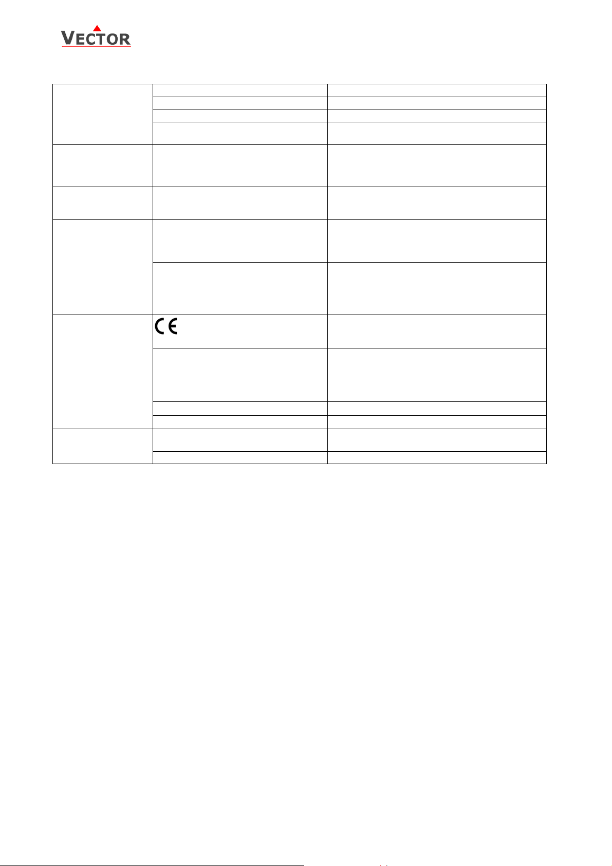
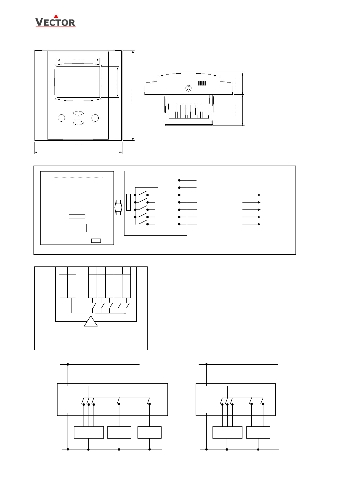
Dimensions
Wiring Diagram
43 (1.7)
88 (3.5)
TLC-FCR-2 Engineering Manual
Space required in flush mounting box:
(H x W x D)
60 x 50 x 30mm (2.4 x 2.0 x 1.2 in.)
30 (1.2)
88 (3.5)
30 (1.2) 21 (0.8)
Distance for mounting screws:
Horizontal and vertical:
45 to 63mm (1.8 to 2.5 in.)
Front part
Plug
CPU
RT
Connection terminals
1
0V AC 2 220V AC
3
Fan Low 4 Fan Med 5 Fan High 6 Open / H 7 Close / C
!
Attention: Switching power is
TLC-FCR-2
Attention: Switching power
is limited to 230VAC, 300W
1
N
2
~
3
DO1
4
DO2
5
DO3
6
DO4
7
DO5
Legend
1: 0V AC Neutral Power Supply
2: 230V AC Power Supply
3: DO1 = Fan Speed Low
4: DO2 = Fan Speed Medium
5: DO3 = Fan Speed High
6: DO4 = Heat for binary actuators
OPEN for 3-point actuators
7: DO5 = Cool for binary actuators
CLOSE for 3-point actuators
N
Fan Low
Fan Medium
Fan High
Heat, OPEN
Cool, CLOSE
Connection Diagram
230V AC L
230V AC L
2
2
1
3 4 5
FAN
1-3
6 7
HEAT
COO
1
3 4 5
FAN
1-3
6 7
3-point
actuator
0V AC N
Subject to alteration
Doc: 70-00-0081, Date: 20081219 © 2008 Vector Controls Ltd. Page 3
0V AC N
Page 4

6
TLC-FCR-2 Engineering Manual
Display and Operation
The operation terminal uses an LCD display and four operation buttons.
1
Legend:
1. 4-digit display of current value, time,
control parameter or set point.
2. Unit of displayed value, °C, °F, % or none
3. Indication of fan speeds
4. 4-digit display of current value, time, control
parameter or set point.
5. Operation modes:
6. Symbols:
Heating Active Cooling Active Schedule Set Fan Active Manual Override Frost Protection
7. Buttons for operating the controller
POWER button: Pressing the button less than 2 sec toggles Economy and comfort modes. Pressing
the button for more than 2 seconds switches the unit off.
UP and DOWN buttons: change setpoints and parameters
OPTION button: used for changing fan speed and accessing advanced setup. Acts as Enter in
parameter changing menu.
8. While the fan is in operation, the Fan symbol will be indicated and the active Fan speed is displayed in the
vertical scale. Activation of heating or cooling coil is indicated by the blinking of the respective symbol in the
lower left corner of the display.
Power Failure
All the parameters and set points are memorized and don’t need to be reentered. Depending on UP05 the unit will
remain switched off, switch on automatically or return to the operation mode it was in before the power failure.
The deluxe version includes a real time clock with a 48h backup battery powered through a super capacitor. The time
does not need to be re-entered after a power failure.
Frost Protection
The controller will enter frost protection mode if the room temperature drops below 5° C (41°F). All heating outputs will
be fully opened. Frost protection mode will be left once the temperature reaches 10°C (50°F). Frost protection display
will remain until a button is pressed. Frost protection can be enabled/disabled using user parameter UP-09
Comfort mode, Economy mode, , OFF Energy Hold Off
5
Operation Modes
• Comfort: The unit is in full operat ion mode. All th e control fu nctions are o perating acco rding to their setpoints .
The unit displays occupied mode.
• Economy: The set point is shifted according to parameters FC-04. The heating parameter is shifted down and
cooling parameter up. The unit displays unoccupied mode. Fan speeds are li mited to low fan speed. Economy
operation may be disabled with UP-06.
• Energy Hold Off (EHO): The unit is switched off. All outputs are off. The t emperature will still be monitored in
order to activate the unit in case of frost. (If frost protection is enabled). Off and current time is displayed.
Activation of operation modes
• Via operation termina l
• Clock: (Deluxe version only) Operatio n mod es may automa tically be switched according to daytime and
weekday. The clock symbol will be indicated if time programs are activated.
• Infrared Remote Controller: (Deluxe version only) use OPR-1 to control the unit remotely
Note: Time programs will not operate, if time is not set.
2
3
4
7
Doc: 70-00-0081, Date: 20081219 © 2008 Vector Controls Ltd. Page 4
Page 5

TLC-FCR-2 Engineering Manual
Clock Operation and Time Schedules (Deluxe Version)
TLC-FCR-2-D contains a real time clock. Up to 16 mode changes (not defined, Off, Economy, Comfort, University mode)
based on weekdays and time may be programmed. See chapter operation on how to program switch times.
The different scheduled mode changes have these effects:
Name on display Function Override reset
no Switching event not used
OFF Operation mode changes to off mode Reset is active
ECO Operation mode changes to economy mode Reset is not active
ON Operation mode changes to comfort mode Re se t is not active
UNI Operation mode does not change Reset is not active
UNI: University mode: This switching mode is used for rooms such as lecture rooms and auditoriums that might be
occupied during a certain time. During this time the reset is not active. The unit will not start itself when UNI mode is
active. It still needs to be manually activated. This is to avoid unnecessary heating or cooling of such rooms while they
are not occupied.
Override reset function: The override reset applies when the unit is manual ly swit ched on, whil e in s cheduled o ff mo de.
The unit will switch automatically off when the reset time defined in UP13 expires. Setting UP13 to 0, disables the
override reset.
A blinking clock indicates that the time needs to be set. Time programs will not operate if the time is not defined. See
chapter operation, advanced settings for instructions on how to set the time.
Error messages
The TLC-FCR-2 may display the following error condition:
Err1: Temperature sensor faulty. The connection to the temperature sensor may be interrupted or the temperature
FP: Frost protection is active.
sensor is damaged. The controller may only be used in manual mod e.
Doc: 70-00-0081, Date: 20081219 © 2008 Vector Controls Ltd. Page 5
Page 6

TLC-FCR-2 Engineering Manual
Operation of the Terminal Unit
Switching ON
The unit is switched on by pressing the POWER button. It will start up in comfort mode.
Changing between COMFORT and ECONOMY
Pressing the POWER button for less than 2 seconds toggles between ECONOMY and COMFORT modes. Economy mode
may be disabled with UP06.
Switching OFF
Pressing the POWER button for more than 2 seconds, will switch the unit off. OFF and current time will be displayed in
the LCD.
Standard display
This display mode is active if no UP/DOWN or OPTION button has been pressed during the previous 30 seconds. The
contents of the large and small digits may be chosen with parameters UP-10 and UP-11.
Pressing UP/DOWN button will show the temperature setpoint in the small digits and room temperature in the large
digits.
Changing of set points
Press UP/DOWN buttons to change temperature setpoint. Changing of set points may be disabled with UP-01.
Fan speed override
Manually change fan speeds by pressing the OPTION button for less than 3 seconds. Repea tedly pressing the OPTION
button will toggle through these fan speed selections: Fan LOW → Fan MEDIUM → FAN HIGH → FAN Auto. Any
selection other than FAN Auto will display the manual override sign. Manual override of fan speeds may be disabled
with UP-02
Accessing advanced settings
Pressing the option button for more than three seconds will start the advanced setup menu. The basic version will only
show heat/cool setup. The deluxe version will allow access to the time setting function.
The large LCD digits display SEL. The advanced setup menu accesses these settings: Hea t / Cool change, Clock setup,
Time schedule. The menu may be left by pressing the POWER button or by not pressing a button for more than 5
minutes.
• Heat / Cool / Fan only change. Pressing the OPTION button toggles Heating – Cooling – Fan only mode.
Access to Heat/Cool change may be disabled with UP-03
Clock Setup and Time Schedule (only available on Deluxe versions)
• Clock Setup. The current time is displayed in the small digits. Pressing the OPTION button will enter the clock
setup. The minutes are blinking and may be changed with the UP/DOWN buttons. Pressing OPTION saves the
minutes and steps to the hours. The hours are blinking. Pressing the OPTION button again will step to the
weekday. DAY1-7 is displayed. Day 1 stands for the first working day (Monday) of a 5-day working week.
(See schedule). Select the day according to current w eekday. Pressing Option again saves the settings and
moves back to the SELECT menu.
• Time Schedules: press the option button while Pro is displayed in the small digi ts. Pro1 is now shown in the
large digits, while the number 1 is blink ing. Select time program by using UP/DOWN buttons. There are a
total of 4 time programs with each 4 switching times available. Enter the time program by pressing the
OPTION button.
1. Activate or deactivate the time program. Choose ON or OFF with the UP/DOWN buttons
2. Select weekday(s) = d1-7, d1-5, d6-7, day1, day2, day3, day4, day5, day6, day7
The next steps define the switching mode and time. The bar indicator on the right side shows programming
progress. There are four switch times for each program.
3. Select desired operation mode. (no, OFF, ECO, ON, UNI), press OPTION to continue
no = disables this switching time
OFF = switches unit Off, enables reset timer
ECO = sets operation mode to On and Economy, disables reset timer
ON = sets operation mode to On and Comfort, disables reset timer
UNI = Does not change operation mode, only disables reset timer
4. Select switching time 00:00 to 23:45 in 15-minute steps; press OPTION to continue.
5. Repeat steps 3 and 4 for each switching time.
Access to time schedules may be disabled with UP-04
Doc: 70-00-0081, Date: 20081219 © 2008 Vector Controls Ltd. Page 6
Page 7

d e f g h j
k l
TLC-FCR-2 Engineering Manual
Operation with OPR-1
The deluxe version may be alternatively operated with an infrared remote
controller.
1. Mode indication, Auto, Dry, Cool, Fan, Heat
2. 2-digit display of setpoint
3. Fan indication
4. 4-digit display of current time or delayed switching time
5. Economy button: Toggles Economy/Comfort mode
6. Mode button, changes operation modes
7. UP/DOWN Button: Set point adjustment buttons
8. FAN Button: Changes fan speed, low – medium – high or Auto
9. Boost button, activates full output for 5 Minutes
10. Time related buttons: Timer, Hour, Minute
11. POWER Button: Operation mode ON – OFF
c
AUTO
24
CLOCK
0:00
SLEEP
Switching ON
The unit is switched on by pressing the POWER button. It will start up in comfort mode.
Changing between COMFORT and ECONOMY
Pressing the SLEEP button toggles between ECONOMY and COMFORT modes.
Switching OFF
Pressing the POWER while the unit is on, will switch the unit o ff. The current time will be displayed in the LCD of OPR-1.
Changing of set points
Only the set points for the temperature loop may be changed. Set point range is 15 to 30 °C.
Changing of fan speeds
Repeatedly pressing the fan speed button steps through low, medium, high and automatic fan speeds. Automatic fan
speed will not be activated in FAN ONLY mode.
Boost
Pressing the boost button activates a 5 minute boost. The output will be fully opened for the period of 5 minutes
independent of demand. This may be used to change stale air during a meeting break or when entering the room.
Clock settings
The remote controller contains a daytime clock. In order to set the clock, press HOUR and MINUTE button together
until the clock starts blinking. Then set the correct time with the HOUR and MINUTE but tons. Confirm by pressing the
TIMER button. The clock of the OPR will set the clock of the controller.
Delayed switching
The unit may be delayed switched on or off using the timer button. Pressing the timer button once will display Timer
ON if currently in OFF mode or TIMER OFF if currently in ON mode. Set the time when the unit is supposed to switch
on or off using the HOUR and MINUTE buttons.
Mode changes
Repeatedly pressing the mode button may activate the following operation modes: HEAT, COOL and FAN ONLY. The
mode change may be disabled using the UP parameters.
Note:
The remote controller is currently only available in °C mode.
ºC
MODE
i
BOOST
TIMER
HOUR
MINUTE
11
Doc: 70-00-0081, Date: 20081219 © 2008 Vector Controls Ltd. Page 7
Page 8

TLC-FCR-2 Engineering Manual
Setting of user parameters
The TLC-FCR-2 is an intelligent controller and can be adapted to fit perfectly into your fan coil application. The control
operation is defined by parameters. The parameters are set during operation by using the standard operation terminal.
The parameters may only be accessed by entering a code. There are two levels of parameters: User operation
parameters for access control settings and Expert parameters for control functions and unit setup. The codes for user
levels and expert levels are different. Only control experts should be given the control parameter code.
The parameters can be changed as follows:
1. Press UP and DOWN button simultaneously for three seconds. The display shows the software version in the
large digits and the software revision in the small digits.
2. Pressing the OPTION button will indicate CODE on the s mall digits and 000 on the large digits.
3. The code for accessing the user parameters is 009
4. Select this using UP or DOWN buttons.
5. Press OPTION button after selecting the correct code.
6. Once logged in, the parameter is displayed immediately.
7. Select the parameters with the UP/DOWN buttons. Change a parameter by pressing the OPTION but to n. The
MIN and MAX symbols show up and indicate that the parameter may be modified now. Use UP or DOWN
buttons to adjust the value.
8. After you are done, press OPTION or POWER in order to return to the parameter selection level.
9. Press the POWER button again so as to leave the menu. The unit will return to normal operation if no button
is pressed for more than 5 minutes.
User Parameters
Parameter Description Setting Range Factory Setting
UP 00 Enable change of operation modes ON, OFF ON (Enabled)
UP 01 Enable change of set points ON, OFF ON (Enabled)
UP 02 Enable manual control of fan speeds ON, OFF ON (Enabled)
UP 03 Enable change of heating/cooling mode ON, OFF W00: ON (Enabled)
UP 04 Enable access to Time programs ON, OFF ON (Enabled)
UP 05 State after power failure:
UP 06 Enable Economy functionality ON, OFF ON (Economy )
UP 07 Celsius or Fahrenheit, Select ON for Fahrenheit, OFF for Celsius ON, OFF OFF (Celsius)
UP 08 Calibration value of temperature sensor . This value is calibrated at
UP 09 Enable frost protection ON, OFF W00 = ON
UP 10 Select contents of Large LCD display in standard mode:
UP 11 Select contents of small LCD display in standard mode
UP 12
Deluxe only
UP 13
Deluxe only
0 = Switched OFF, 1 = Switched ON, 2 = state before power failure
manufacturing of the thermostat. If required it is possible to shift
the temperature –10° to +10° in 0.1° K steps.
00 = OFF
01 = Setpoint
02 = Temperature Sensor
03 = Output Fan Speed
04 = Clock
(use table of UP 10)
Clock display type:
OFF = Show 24hour clock
ON = Show 12hour clock (AM, PM)
Reset timer for override mode: Only available for deluxe version
0 = Reset of override mode is not active.
1…255 = delay in minutes to switch off device if ON/Economy
mode is activated while the unit is scheduled to be in OFF
mode
0, 1, 2 2
-10…10 0
0…4 02
0…4 04 Deluxe:
ON, OFF OFF (24h)
0…255 60 (Min)
W01: OFF (Disabled)
(Frost Protection)
W01 = OFF
(No Frost Protection)
Temperature
show clock
01 Standard:
show setpoint
Subject to alteration
Doc: 70-00-0081, Date: 20081219 © 2008 Vector Controls Ltd. Page 8
Page 9

T [K]
TLC-FCR-2 Engineering Manual
Control Functions
The controller is designed to control fan coil systems with up to three fan speeds. The fan speeds may be controlled to
run manual or automatic. In automatic mode, the controller will change fan speeds according to the t emperature
difference of room temperature and setpoint.
Setpoint
• Minimum and Maximum Set Point Limits: Limits the adjustable range of the loop set point. The limits for
heating and cooling sequence may be chosen individually.
Control Sequence
• 4-pipe or 2-pipe system: 4-pipe systems use one heating and one cooling stage. Heating and cooling mode
will switch according to demand. A delay is implemented to prevent unnecessary switching between heating
and cooling mode: Heat – Cool change over delay.
• Economy set point shift X
heating set point W
shift X
• Dead Zone Span X
change the heating or cooling set points within adjustab le limits.
• Switching Hysteresis: Defines the difference between switching on and switching off of an output. A small
hysteresis will increase the number of switching cycles and thus the wear on associated equipment.
• Delay OFF: Prevents a too short running cycle for the heating or cooling stage by setting a minimum running
time. Delay OFF applies to all heating and cooling stages.
• Delay ON: Prevents a too short stopping cycle for heating or cooling stage by setting a minimum stopping
time. Delay ON applies to all heating and cooling stages.
• Step by step switching: In order to reduce the startup load of large fan motors, fan stages will be switched
on and off step by step, going through low and medium before activating high fan sp eeds.
• Fan Off delay: In case heating or cooling has been active and the unit is switched off or reached the set
point, a 60 seconds fan off delay is activated to prevent over heating of a heating stag e or condensation on a
cooling coil.
• Mold Protection. The fan will not stop when the setpo int is reached while this parameter is activated. This
way the room will still be ventilated although there is no need to vary the temperature. The valve will still be
controlled according to temperature need. The fan will still switch off once the unit is set to OFF.
SBY
Fan Low
.
Heating Mode Cooling Mode
is reduced and the cooling set point WC increased by the value of the Economy set point
H
: The dead zone span lies between the heating and the cooling set point. The user can
DZ
HF
T Room Temperature wH Setpoint Heating Mode DZ Dead Zone
X
Switching Span Heating wC Setpoint Cooling Mode
FH
XFC Switching Span Cooling HF Hysteresis
: This function shifts the set point while the operation mode is Economy. The
SBY
Mold protection
ON
W
W
XFH
D
X
Z
FC
Output Configuration
Two options are available: 3-point or binary.
3-point output
If 3-point is selected a 3-point actuator may be driven. The actuator has an open input and a close input. Applying
power to the Open input will drive the valve or damper open, applying power to the close input will drive the valve or
damper to the closed position.
The running time of the actuator may be preset. We recommend to enter the maximum running time under maximum
load in order to make sure that the valve can fully close and fully open in any circumstance.
In order to open the valve or damper DO4 will be activated for the preset amount of time. After the expiration of the
running time DO4 and DO5 will be OFF. The valve is closed by activating DO5 for the preset amount of time.
Binary output
Two devices may be controlled in case the 3-point actuator setting is OFF. DO4 will control a heating and DO5 a
cooling device.
Doc: 70-00-0081, Date: 20081219 © 2008 Vector Controls Ltd. Page 9
Page 10

TLC-FCR-2 Engineering Manual
Configuration parameters for firmware version 2.2
The TLC-FCR-2 can be adapted to wide variety of applications. The adaptation is done with parameters. The
parameters can be changed on the unit without the need of additional equipment.
Identifying the firmware version
The parameters and functionality of controller depend on its firmware revision. It is therefore important to use a
matching product version and parameter set. The firmware version is shown on the large LCD digits when pressing UP
and DOWN buttons for more than 3 seconds simultaneously.
Control Parameters (Access Code: 241)
Warning! Only experts should change these settings! See user parameters for login procedure.
Parameter Description Range Standard
FC 00 Minimum setpoint limit in Heating mode -40…60°C (160°F) 16°C (61°F)
FC 01 Maximum setpoint limit in Heating mode -40…60°C (160°F) 24°C (76°F)
FC 02 Minimum setpoint limit in Cooling mode -40…60°C (160°F) 18°C (65°F)
FC 03 Maximum setpoint limit in Cooling mode -40…60°C (160°F) 30°C (87°F)
Controls configuration
FC 04 Economy temperature shift 0…100°C (200°F) 5.0°C (10°F)
FC 05 Switching Span Heating,
Setting this value to 0 disables the auto fan speed function in
heating mode
FC 06 Switching Span Cooling
Setting this value to 0 disables the auto fan speed function in
cooling mode
FC 07 Switching Hysteresis 0…100°C (200°F) 0.5°C (1°F)
FC 08 Mold Protection: OFF = Disabled, ON = Enabled ON, OFF OFF
FC 09 Delay OFF (Minimum running time) 0…255s 10s
FC 10 Delay ON (Minimum stopping time) 0…255s 10s
FC 11 2-pipe or 4-pipe system: OFF = 2-pipe, ON = 4-pipe system ON, OFF OFF
FC 12 Dead zone between heating & cooling set point XDZ 0…100°C (200°F) 1.0°C (2°F)
FC 13 Delay on Heat/Cool change over 0…255 min 5 min
Output configuration
FC 14 Output setting, Binary or 3-point:
OFF = Binary (DO4 Heating, DO5 Cooling)
ON = 3-point output (DO4 OPEN, DO5 CLOSE)
FC 15 Running Time in 3-point mode 0…255 s 90 s
0…100°C (200°F) 1.5°C (3°F)
0…100°C (200°F) 1.0°C (2°F)
ON, OFF OFF
Doc: 70-00-0081, Date: 20081219 © 2008 Vector Controls Ltd. Page 10
 Loading...