

Page 1
Fan Coil Controller TLC3-FCR-M-U-230
Fan Coil Controller TLC3-FCR-M-U-230
Fan Coil Controller TLC3-FCR-M-U-230
Item Name
Item code
Variant
Power
Features
TLC3-FCR-M2-U-24
40-10 0141
Standard
24VAC/DC
Fan coil controller with:
1 TI int, 1 external input
3 DO (Relay) Fan control
1AO (0-10VDC) PID valve control
TLC3-FCR-M2-U-120
40-10 0151
120VAC
TLC3-FCR-M2-U-230
40-10 0102
230VAC
TLC3-FCR-M2-U-D-24
40-10 0146
Deluxe
24VAC/DC
TLC3-FCR-M2-U-D-120
40-10 0156
120VAC
TLC3-FCR-M2-U-D-230
40-10 0103
230VAC
TLC3-FCR-M4-U-24
40-10 0142
Standard
24VAC/DC
1 TI int
3 DO (Relay) Fan control
2AO (0-10VDC) PID valve control
TLC3-FCR-M4-U-120
40-10 0152
120VAC
TLC3-FCR-M4-U-230
40-10 0106
230VAC
TLC3-FCR-M4-U-D-24
40-10 0147
Deluxe
24VAC/DC
TLC3-FCR-M4-U-D-120
40-10 0157
120VAC
TLC3-FCR-M4-U-D-230
40-10 0107
230VAC
-W01
-1
Cooling only
Add to name or code for special
settings
Power Supply
Operating Voltage
210 – 250 V AC 50/60 Hz
Power Consumption
Max 1W, 1.5VA
Electrical Connection
Terminal Connectors
Deluxe type only:Power backup for real time clock
Min 48h if charged for 24h
Signal Inputs
Temperature Inputs
Range
Accuracy
RT Int., Ext. (Sxx-Tn10 sensor)
0…50 °C (32…122 °F)
0.5°C (1°F)
Signal Outputs
Digital Switching Outputs
Switching Type
AC Switching power
Insulation strength
between relays contacts and system electronics:
between neighboring relays contacts
DO1 to DO3
Relays
0…250V AC 2A max. each output
3750V AC to EN 60 730-1
1250V AC to EN 60 730-1
Analog Outputs
Output Signal
Minimum impedance / maximum load
AO1, For TLC3-FCR-M4 AO2
DC 0...10 V
10kOhm, ±1mA.
Operation
Climatic Conditions
Temperature
Humidity
To IEC 721-3-3
class 3 K5
0°C …50°C (32°F…122°F)
<95% R.H. non-condensing
Environment
Transport & Storage
Climatic Conditions
Temperature
Humidity
Mechanical Conditions
To IEC 721-3-2 and IEC 721-3-1
class 3 K3 and class 1 K3
-25°C…70°C (-13°F…158°F)
<95% R.H. non-condensing
class 2M2
conformity
EMC Directive
Low Voltage Directive
2004/108/EC
2006/95/EC
Standards
Product standards
Automatic electrical controls for household and similar use
Special requirement on temperature dependent controls
EN 60 730 –1
EN 60 730 – 2 - 9
Electromagnetic compatibility for
domestic sector
Emissions: EN 60 730-1
Immunity: EN 60 730-1
Degree of Protection
IP30 to EN 60 529
Pollution Class
II (EN 60 730-1)
Safety Class: for -24 types
for -230 types
III (IEC 60 536)
II (IEC 60 536)
Overvoltage Category: for -24 types
for -230 types
I (EN 60 730-1)
III (EN 60 730-1)
RoHS
Compliant
General
Dimensions (H x W x D) Front part:
Power case:
16 x 73 x 113mm (0,7 x 2.9 x 4.5 in.)
60 x 50 x 32mm (2.4 x 2.0 x 1.3 in.)
Material: Cover, back part
Mounting Plate
ABS plastic (UL94 class V-0)
Galvanized Steel
Weight (including package)
Standard: 295g (10.4oz)
Deluxe (-D): 305g (10.7oz)
32 (1.3)
16 (0.7)
113 (4.5)
73 (2.9)
Space required in flush mounting box:(H x W x D) 60 x 50 x 32mm (2.4 x 2.0 x 1.3 in.)
Distance for mounting screws:Horizontal and vertical: 45 to 63mm (1.8 to 2.5 in.)
X
T INT
0V
230V AC
2
L
TLC3-FCR-M2-U-230
1
N
7
X1
X
T EXT
IN
8
U1
AO1
3
Y1
Fan
Low
4
Y2
Fan
Med
5
Y3
Fan
High
6
M
SGND
X
T INT
0V
230V AC
2
L
TLC3-FCR-M4-U-230
1
N
8
U1
AO1
Heat
3
Y1
Fan
Low
4
Y2
Fan
Med
5
Y3
Fan
High
6
M
SGND
7
U2
AO2
Cool
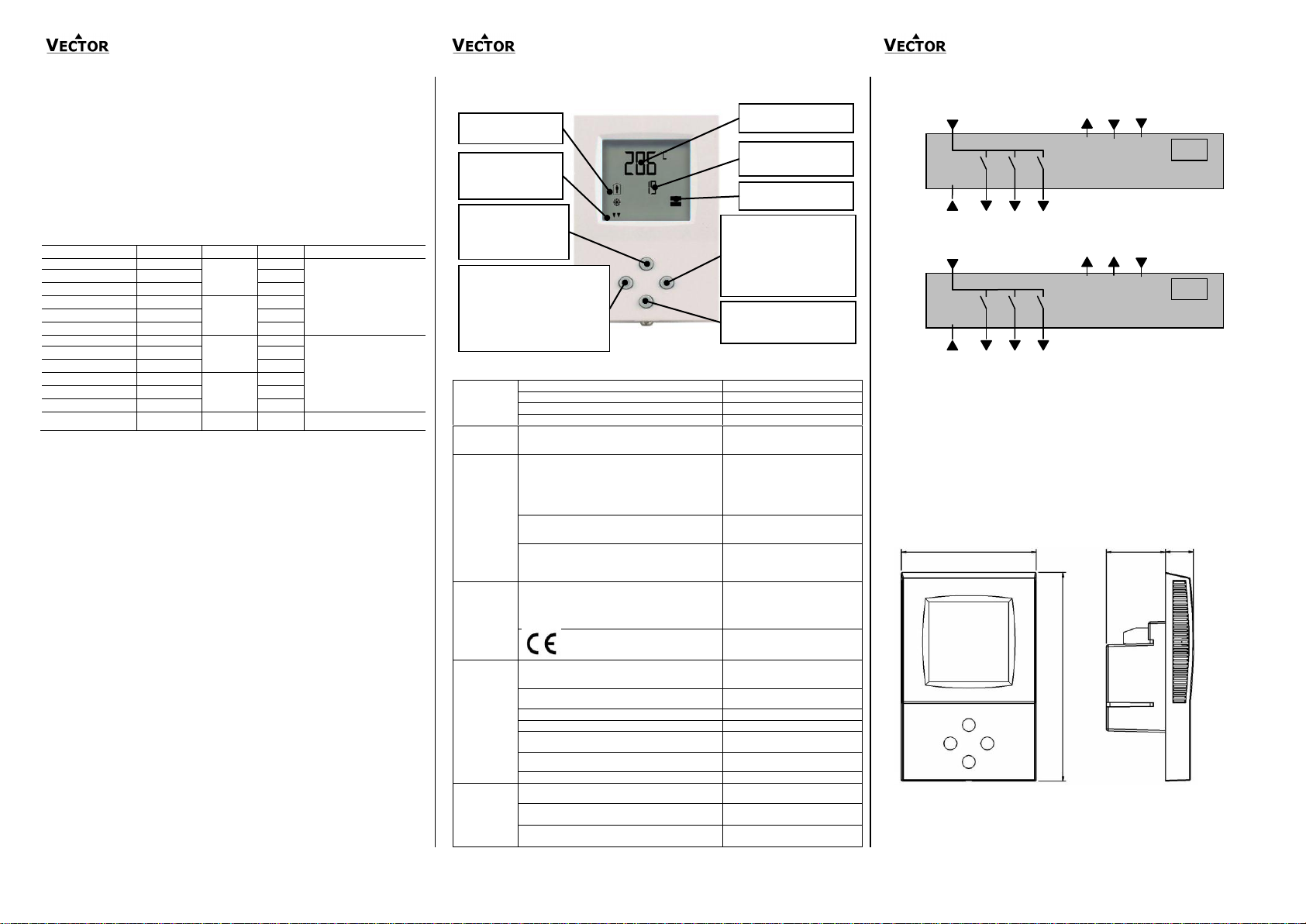
Left (POWER): Press < 2 sec.: Toggle
Economy -Comfort mode or switch from
OFF to ON
Press > 2 sec.: Turn unit OFF. Text OFF
displayed with current time (deluxe)
temperature (standard)
(Parameter setting: Return to previous
level. ESC)
Up :Increase setpoint
(Parameter setting: scroll
menu options and
parameters)
Down: Decrease setpoint
(Parameter setting: scroll menu
options and parameters)
Mode
Display of operation mode
Large Digits: Display of input
or parameter value.
Indicators
1 Remote temperature
sensor
Vertical Bar: Fan speed or
proportional output
Small Digits: Display of
setpoint, clock or parameter
number.
Right (OPTION)
Press < 2 sec.: Select fan speed:
Low, medium, high or auto
Press > 2 sec.: Manual H/C change
(Parameter setting: ENTER to
select menu option, accept
parameter change)
TLC3-FCR-M-U-230, Programmable PID Fan Coil Controller
Features
Proven PID controls algorithm reduces room temperature fluctuations and energy consumption
Low power energy consumption: < 1W per unit
Relays switching for outputs each up to 300W
Temperature control for 2 or 4-pipe fan coil systems.
Automatic fan control for three stage fans.
Cost saving option with Economy functionality and set point limitations
Control for modulating heating, cooling and fan only operation modes
Deluxe Version:
Clock and time schedule functions with power failure clock protection
Blue backlight for LCD
Infrared remote controller option:
With special features for Boost and delayed switching on or off
Ordering
Selection of fans
Do not directly connect devices that exceed 250 VAC, 2(1.2) A. Observe startup current on inductive loads!
Do not connect more than one fan coil unit to one controller.
Modulating Actuators:
Choose actuators with an input signal type of 0-10V DC or 2-10V DC. Observe maximal signal current of
1mA!
Mounting location
Install the controller on an easy accessible interior wall, approx. 1.5 m above the floor in an area of
average temperature.
Avoid direct sunlight or other heat sources, e.g. the area above radiators and heat emitting equipment.
Avoid locations behind doors, outside walls and below or above air discharge grills and diffusers.
Location of mounting is less critical if external temperature sensors are used.
Installation
1. Connect the wires to be connected to the terminals of the power case according to wiring diagram
2. Install the mounting plate to the flush mounting box. Make sure that the nipple with the front holding
screw is facing to the ground. Make sure the mounting screw heads do not stand out more than 5
mm (0.2”) off the surface of the mounting plate.
3. Slide the two latches located on the top of the front part into the hooks at the upper side of the
mounting plate.
4. Carefully lower the front part until the interconnector reaches the mounting-plate. Continue
pressing in a gentle way until the front part is fully connected. While inserting the connectors, a
slight resistance can be felt. This is normal. Do not use excessive force!
5. With a Philips-type screw driver of size #2, carefully tighten the front holding screw to secure the
front part to the mounting plate. This screw is located on the front lower side of the unit. There is no
need to tighten the screw too much.
Power Failure
Upon power-interruption, all parameters and setpoints are memorized in non-volatile memory and therefore
do not have to be re-entered again.
Error messages
Err1: Error temperature sensor. The internal temperature sensor may be damaged or not present.
FP: Steady: Frost protection is active.
Blinking: Frost protection activated in the past and is now inactive. Confirm with OPTION key.
Display and Operation
Technical Specification
Wiring Diagram
Description:
N Power supply: 0V Neutral
L Power supply: 230VAC
Y1 Binary output 230V AC: Fan speed low
Y2 Binary output 230V AC: Fan speed medium
Y3 Binary output 230V AC: Fan speed high
TLC3-FCR-M2-U:
M Signal common: Common 0 potential for inputs and analog outputs.
X1 External input: NTC 10kΩ @ 25°C (77°F) or open contact to SGND
U1 Analog output: 0…10 V DC
TLC3-FCR-M4-U:
M Signal common: Common 0 potential for inputs and analog outputs.
U2 Analog cooling output: 0…10 V DC
U1 Analog heating output: 0…10 V DC
Dimensions
Doc: 70-00-0180 V3.0 Date: 20110928 © Vector Controls GmbH, Switzerland Subject to alteration
Page 2
Fan Coil Controller TLC3-FCR-M-U-230
Fan Coil Controller TLC3-FCR-M-U-230
Fan Coil Controller TLC3-FCR-M-U-230
Parameter
Description
Range
Standard
UP 00
Enable change of operation modes,
ON, OFF
ON (Enabled)
UP 01
Enable change of set points
ON, OFF
ON (Enabled)
UP 02
Enable manual control fan speeds
ON, OFF
ON (Enabled)
UP 03
Enable manual change of Heating/Cooling Mode.
Applies only for 2-pipe or 4-pipe systems.
ON, OFF
W00 = ON
W01 = OFF
UP 04
Enable Access to time programs
ON, OFF
ON (Enabled)
UP 05
State after power failure: 0 = OFF, 1 = ON, 2 = Last State
0, 1, 2
2
UP 06
Enable Economy (unoccupied) Mode.
Shift the setpoint to a lower temperature in winter or higher
temperature in summer in order to save energy. May be
activated through the POWER button, or with the external input
(typically for key card switches in hotel rooms or motion
detectors for meeting rooms.)
ON, OFF
ON
(Economy )
UP 07
Celsius or Fahrenheit, OFF for Celsius, ON for Fahrenheit
ON, OFF
OFF (Celsius)
UP 08
Calibrateinternal temperature sensor
–10° to +10° in 0.1° steps. (Sensor is factory calibrated, use
this feature for field adjustment only as required.)
-10…10
0
UP 09
Enable Frost Protection.
Activates the output independent of operation mode when the
control temperature drops below 5°C or 41°F. The controller
returns to normal operation when the temperature increases
above 10°C or 50°F.
ON, OFF
W00 = ON
W01 = OFF
UP 10
Select contents of Large LCD display in standard mode:
0…4 02
Temperature
00 = OFF
01 = Setpoint
02 = Temperature Sensor
03 = Output Fan Speed
04 = Clock
UP 11
Select contents of small LCD display in standard mode
(use table of UP 10)
0…4
Standard:
01 Setpoint
Deluxe:
04 Clock
UP 12
Contents of vertical bar in standard mode
OFF = Fan Speed: 0 – 3 levels
ON = Control output 0 – 10 levels
ON, OFF
OFF (FAN)
UP 13
Clock display type: Only available for deluxe version
OFF = Show 24hour clock
ON = Show 12hour clock (AM, PM)
ON, OFF
OFF (24h)
UP 14
Reset timer for override mode: Only available for deluxe version
0 = Reset of override mode is not active.
1…255 = delay in minutes to switch off device if ON/Economy
mode is activated while the unit is scheduled to be
in OFF mode
0…255
60 (Min)
Parameter
Description
Range
Standard
FC 00
Minimum setpoint limit in Heating mode
-40-60°C (160°F)
16°C (61°F)
FC 01
Maximum setpoint limit in Heating mode
-40-60°C (160°F)
24°C (75°F)
FC 02
Minimum setpoint limit in Cooling mode
-40-60°C (160°F)
18°C (64°F)
FC 03
Maximum setpoint limit in Cooling mode
-40-60°C (160°F)
30°C (86°F)
FC 04
Economy (unoccupied) Mode temperature shift:
The comfort (occupied) setpoint is shifted by the value
set with parameter. If heating is active the comfort
setpoint will be decreased, if cooling is active, the
setpoint will be increased. (Enable with UP06.)
0…10.0K (20°F)
5.0°C (10°F)
FC 05
Switching Span Heating,
Setting this value to 0 limits fan to single fan speed in
heating mode
0…10.0K (20°F)
1.5°C (3.0°F)
FC 06
Switching Span Cooling
Setting this value to 0 limits fan to single fan speed in
cooling mode
0…10.0K (20°F)
1.0°C (2.0°F)
FC 07
Switching Hysteresis is the difference between
switching on and switching off. A small hysteresis will
increase the number of switching cycles and thus the
wear on fan and relays contacts.
0…10.0K (20°F)
0.5°C (1°F)
FC 08
Mold Protection:
In mold protection, the fan keeps running independent
of temperature as long as the unit is switched on.
ON, OFF
OFF
FC 09
Switching delay min running time of fan speed. Prevents
the fan from switching in too short intervals.
0…255 s
10s
FC 10
Switching delay min stopping time of fan speed.
Prevents too short restart times, once a fan speed has
been switched off.
0…255 s
10s
FC 11
Control option:
0 = Cooling only
1 = Heating only
2 = 2-pipe system
3 = 4-pipe system
-M2: 0…2
-M4: 0…3
-M2: W00 = 2
-M4: W00 = 3
W01 = 0
W02 = 1
W03 = 2
W04 = 3
FC 12
Dead Zone Span:
The Dead Zone Span lies between the heating and the
cooling setpoint. The output is off while the temperature
is within the dead zone span. A negative dead zone is
not possible.
0…100°C (200°F)
1.0°C (2°F)
FC 13
Heat/Cool Changeover Delay (if set to FC11 = 3):
A demand to switch between heating and cooling must
persist for the length of time set with this parameter
before the controller switches. Prevents activation of a
sequence during a short-term change in temperature in
order to protect equipment (with control overshoot for
example)
0…255 min
5 min
FC 14
P – band heating XPH
0…10.0K (20°F)
2.0°C (4.0°F)
FC 15
P – band cooling XPC
0…10.0K (20°F)
2.0° (4.0°F)
FC 16
KIH, Integral gain heating, in 0.1 steps,
0 disables ID part
low value = slow reaction
high value = fast reaction
0…25.5
0.0
FC 17
KIC, Integral gain cooling, in 0.1 steps
0…25.5
0.0
FC 18
Configuration of analog output signal
0 = 0-10V
1 = 2-10V
2 = Manual override (useful for commissioning)
When low fan speed: 25% output
When medium fan speed 50% output
When high fan speed 100% output
0-2
0 (0-10V)
FC 19
External input:
0 = No external input
1 = External temperature sensor
2 = Occupation sensor – Comfort / Economy
3 = Occupation sensor – Comfort / Off
4 = Heat / Cool changeover
5 = Key card with alternative setpoint
0…8
0
FC 20
Activation delay (Minutes) = the time the binary input
needs to be open before economy/off mode is activated.
0…255 min
5
FC 21
Auto-changeover limit heating FC20 = 4
or economy setpoint in heating mode if FC20 = 5
-40…60°C (160°F)
16°C (61°F)
FC 22
Auto-changeover limit cooling FC20 = 4
or economy setpoint in cooling mode if FC20 = 5
-40…60°C (160°F)
28°C (82°F)
FC19 = 0
Input not used
FC19 = 1
External control
input
The external sensor is the control input. The internal
sensor will be disabled.
FC19 = 2
Switching Economy
and Comfort modes
Economy (unoccupied) and Comfort (occupied) modes
are controlled through an external contact by connecting
the input through a dry contact to signal common. This
function may be used together with key card switches for
hotels or motion detectors for offices.
FC19 = 3
Switching Energy
Hold OFF and
Comfort modes
Opening the input will force the unit into the OFF
operation mode. The operation mode cannot be
overridden by using the terminal. Connecting the input to
signal common returns control of the operation mode to
the terminal. This function may be used as window
contact to prevent loss of energy.
FC19 = 4
Heat – Cool
changeover
Switch heating and cooling mode based on supply media
or outside temperature or binary contact. See below for
further details.
FC19 = 5
Key card with
alternative setpoint
As with FC19 = 2, the key card function switches economy
(unoccupied) and comfort (occupied) modes. Instead of
using the setpoint shift, the setpoints in unoccupied mode
are defined by parameter FC21 and FC22.
Change over mode FC19=4
Relation FC21 to
FC22
Example
FC21
Example:
FC22
Supply media
FC21 > FC22
25°C (77F)
18°C (64F)
Outside temperature
FC21 < FC22
15°C (59F)
25°C (77F)
Dry contact: Heating if contact closed
FC21 > FC22
25°C (77F)
15°C (59F)
Dry contact: Cooling if contact closed
FC21 < FC22
15°C (59F)
25°C (77F)
Configuration parameters for firmware version 3.0
The TLC3-FCR-M-U can be adapted to wide variety of fan coil applications. The adaptation is done with
parameters. The parameters can be changed on the unit without the need of additional equipment.
Identifying the firmware version
The parameters and functionality of controller depend on its firmware revision. It is therefore important to use
a matching product version and parameter set. The firmware version is shown on the large LCD digits when
pressing UP and DOWN buttons for more than 3 seconds simultaneously.
Changing parameters
The parameters may only be accessed by entering a code. There are two levels of parameters: User
operation parameters for access control settings and Expert parameters for control functions and unit setup.
The codes for user levels and expert levels are different. Only control experts should be given the control
parameter code.
The parameters can be changed as follows:
1. Press UP and DOWN button simultaneously for three seconds. The display shows the
software version in the large digits and the software revision in the small digits.
2. Pressing the OPTION button will indicate CODE on the small digits and 000 on the large
digits.
3. The code for accessing the user parameters is 009, for controls settings it is 241 (scroll
backwards by pressing the DOWN button)
4. Select this using UP or DOWN buttons.
5. Press OPTION button after selecting the correct code.
6. Once logged in, the parameter is displayed immediately.
7. Select the parameters with the UP/DOWN buttons. Change a parameter by pressing the
OPTION button. The MIN and MAX symbols show up and indicate that the parameter may
be modified now. Use UP or DOWN buttons to adjust the value.
8. After you are done, press OPTION or POWER in order to return to the parameter selection
level.
9. Press the POWER button again so as to leave the menu. The unit will return to normal
operation if no button is pressed for more than 5 minutes.
User Parameters (Access Code: 09)
Control Parameters (Access Code: 241)
Warning! Only experts should change these settings!
Set point limits
Fan control sequence
Configuration of outputs
Configuration of inputs
Configuring the function of the external input
Configuring auto changeover input if FC19 = 4:
PID control sequence
Proportional control(P-band)
The proportional control function calculates the output based on the difference between setpoint and
measured value. The proportional band (P-band) defines the difference between setpoint and measured
value which will result in a 100% output. Setting the proportional band to 0 disables proportional control.
Integral gain KI
The integral gain defines how fast the output increases in case the setpoint is not met by the room
temperature. A low value indicates a slow reaction, a high value a fast one. If the value is chosen too high,
the controller will start to swing. Depending on the room size and heating / cooling equipment used a value
between 0.1 and 1.5 should be sufficient. Below are suggested values:
Heating: KIH: 0.1-0.5
Cooling: KIC: 0.3-0.8
Doc: 70-00-0180 V3.0 Date: 20110928 © Vector Controls GmbH, Switzerland Subject to alteration
The auto changeover function automatically changes heating and cooling mode based on supply
media temperature or outdoor temperature. The difference between the two is in the values of the
changeover limits FC21 and FC22. See table below for recommended settings.
Heating and cooling may be as well changed by an open contact switched to signal ground. Note: all
signal ground levels of involved controllers must be the same in case more than one controller is
switched.
Recommended settings for FC21 and FC22:
 Loading...