

Page 1
TLC3-FCR Engineering Manual
Item Name
Item code
Variant
Power
Features
TLC3-FCR-24
TLC3-FCR-24-W01
40-10 0128
40-10 0128-01
Standard
Cooling only
24VAC/DC
Fan coil controller with:
1 TI internal
3 DO (Relay) Fan control
1 DO (Relay) Binary valve control
TLC3-FCR-230
TLC3-FCR-230-W01
40-10 0110
40-10 0110-01
Standard
Cooling only
230VAC
TLC3-FCR-D-24
TLC3-FCR-D-24-W01
40-10 0133
40-10 0133-01
Deluxe
Cooling only
24VAC/DC
TLC3-FCR-D-230
TLC3-FCR-D-230-W01
40-10 0111
40-10 0111-01
Deluxe
Cooling only
230VAC
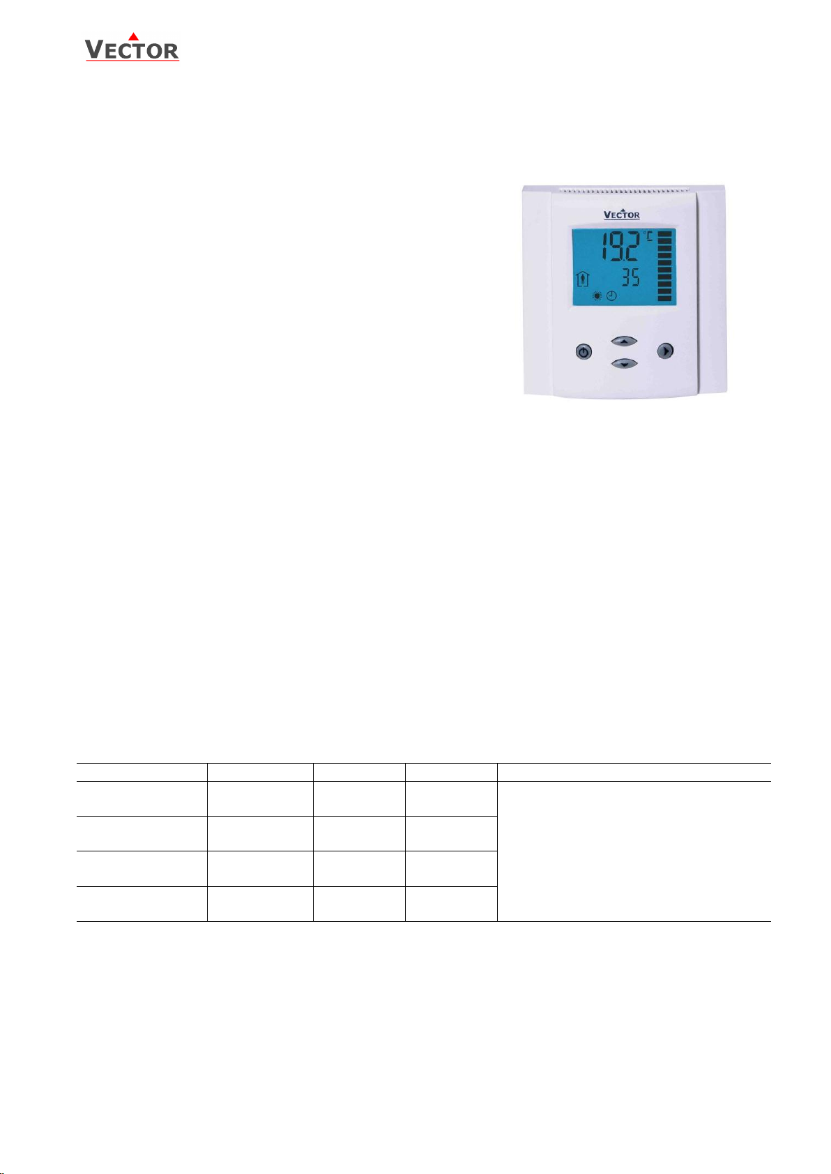
TLC3-FCR Intelligent Fan Coil Controller
Features
The PWM control option reduces room temperature
fluctuations and energy consumption
Low power energy consumption: < 1W per unit
Temperature control for 2-pipe fan coil systems.
Automatic fan control for three stage fans.
Cost saving option with Economy functionality and set point
limitations
Control for single stage heating, cooling and fan only
operation modes
Password protected programmable user and control
parameters
o Setpoint range limitation
o Access control for setpoints, fan speeds and mode
change
o Access control for heat/cool change and time
programs
o Select your display contents
o Selectable behavior after return from power failure
Temperature display in Celsius or Fahrenheit
Deluxe Version:
Clock and time schedule functions with power failure protection
Blue backlight for LCD
Infrared remote controller option:
With special features for Boost and delayed switching on or off
Applications
Air Only Systems: Three stage fans for single duct systems with up to one binary output for auxiliary heating
and cooling devices.
Air/Water Systems: Induction units, fan coil units for 2-pipe systems with one binary output for a spring
return valve.
General Description
The TLC3-FCR is a stand-alone electronic fan coil controller with one control loop. The TLC3-FCR features 1 internal
NTC temperature sensor and four binary outputs (Relays).
A detailed parameterization is possible with the use of a simple configuration routine. The TLC3-FCR can be configured
using the standard operation terminal. No special tools or software is required.
Ordering
Selection of actuators and fans
Binary auxiliary devices: E.g. fans, on/off valves, etc. Do not directly connect devices that exceed 2(1.2)A. Observe
startup current on inductive loads! Do not connect more than one fan coil unit to one controller.
Doc: 70-00-0198, V3.0 Date: 20120403 © Vector Controls GmbH, Switzerland Page 1
Subject to alteration
Page 2
TLC3-FCR Engineering Manual
Power Supply
Operating Voltage
-24
-230
AC voltage: 50/60Hz
22-26V AC/DC
210–250 VAC
Power Consumption
Max 1W, 1.5 VA
Electrical Connection
Terminal Connectors
Deluxe type only:
Power backup for real time clock
Min 48h if charged for 24h
Signal Inputs
Temperature Inputs
Range
Accuracy
Internal
0…50 °C (32…122 °F)
0.5°C (1°F)
Signal Outputs
Digital Switching Outputs
Switching Type
AC Switching power
Insulation strength
between relays contacts and system electronics:
between neighboring relays contacts
DO1 to DO4
Relays
0…250V AC 2A max. each output
3750V AC to EN 60 730-1
1250V AC to EN 60 730-1
Environment
Operation
Climatic Conditions
Temperature
Humidity
To IEC 721-3-3
class 3 K5
0°C …50°C (32°F…122°F)
<95% R.H. non-condensing
Transport & Storage
Climatic Conditions
Temperature
Humidity
Mechanical Conditions
To IEC 721-3-2 and IEC 721-3-1
class 3 K3 and class 1 K3
-25°C…70°C (-13°F…158°F)
<95% R.H. non-condensing
class 2M2
Standards
conformity
EMC Directive
Low Voltage Directive
2004/108/EC
2006/95/EC
Product standards
Automatic electrical controls for household and similar use
Special requirement on temperature dependent controls
EN 60 730 –1
EN 60 730 – 2 - 9
Electromagnetic compatibility for
domestic sector
Emissions: EN 60 730-1
Immunity: EN 60 730-1
Degree of Protection
IP30 to EN 60 529
Pollution Class
II (EN 60 730-1)
Safety Class: for -24 types
for -120 and -230 types
III (IEC 60 536)
II (IEC 60 536)
Overvoltage Category: for -24 types
for 120 and -230 types
I (EN 60 730-1)
III (EN 60 730-1)
General
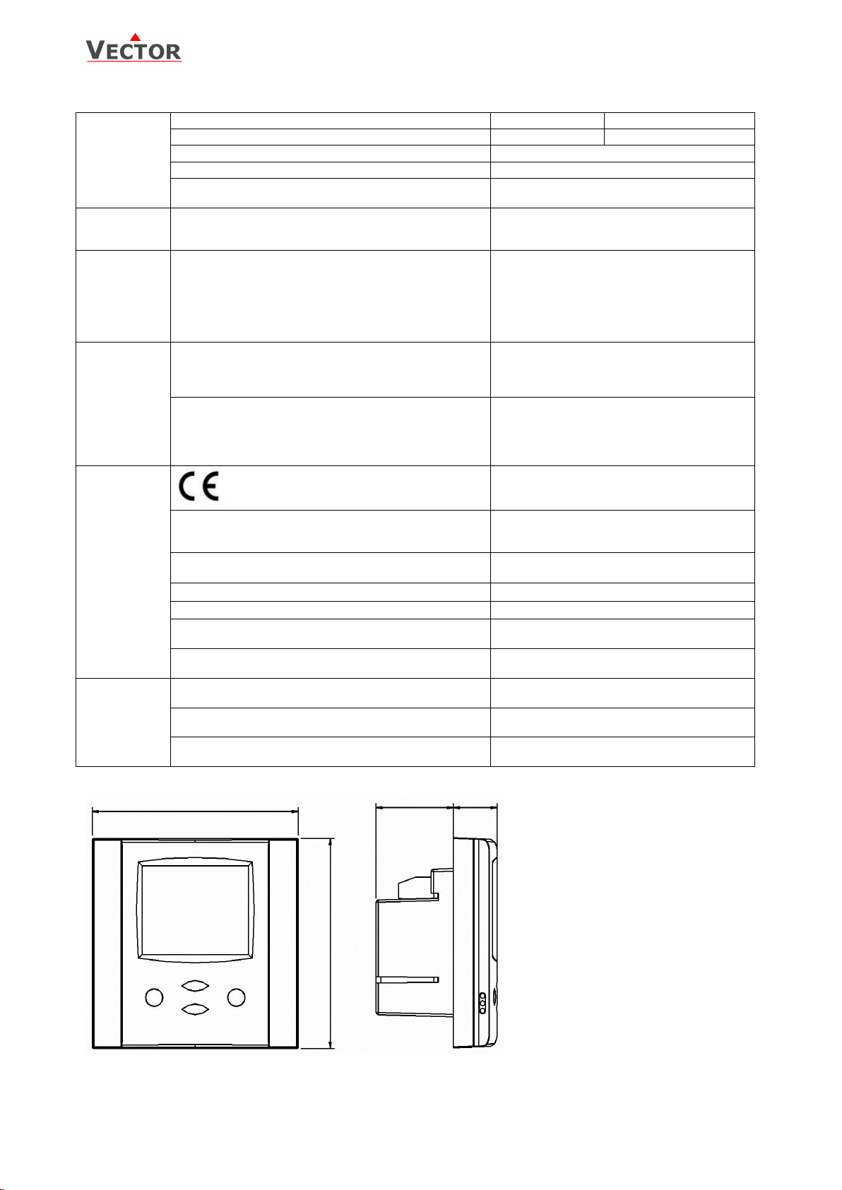
Dimensions (H x W x D)
Front part: 21 x 88 x 88mm (0.8 x 3.5 x 3.5 in.)
Power case: 60 x 50 x 32mm (2.4 x 2.0 x 1.3 in)
Material: Cover, back part
Mounting Plate
ABS plastic (UL94 class V-0)
Galvanized Steel
Weight (including package) for -24 types
for -230 types
standard: 265g (9.3oz), deluxe: 275g (9.7oz)
standard: 295g (10.5oz), deluxe: 305g (10.8oz)
88 (3.5)
32 (1.2)
88 (3.5)
21
(0.8)
Space required in flush mounting box:
(H x W x D)
60 x 50 x 32mm (2.4 x 2.0 x 1.26 in.)
Distance for mounting screws:
Horizontal and vertical:
45 to 63mm (1.8 to 2.5 in.)
Technical Specification
Dimensions
Doc: 70-00-0198, V3.0 Date: 20120403 © Vector Controls GmbH, Switzerland Page 2
Subject to alteration
Page 3
TLC3-FCR Engineering Manual
X
T INT
0V
230V AC
2
L
TLC3-FCR
1
N
3
Y1
Fan
Low
4
Y2
Fan
Med
5
Y3
Fan
High
6
Y4
Valve
Subject to alteration
Mounting location
Install the controller on an easy accessible interior wall, approx. 1.5 m above the floor in an area of average
temperature.
Avoid direct sunlight or other heat sources, e.g. the area above radiators and heat emitting equipment.
Avoid locations behind doors, outside walls and below or above air discharge grills and diffusers.
Location of mounting is less critical if external temperature sensors are used.
Installation
1. Connect the wires to be connected to the terminals of the power case according to wiring diagram
2. Install the mounting plate to the flush mounting box. Make sure that the nipple with the front holding screw is
facing to the ground. Make sure the mounting screw heads do not stand out more than 5 mm (0.2”) off the
surface of the mounting plate.
3. Ensure that the jumpers are set correctly.
4. Slide the two latches located on the top of the front part into the hooks at the upper side of the mounting plate.
5. Carefully lower the front part until the interconnector reaches the mounting-plate. Continue pressing in a gentle
way until the front part is fully connected. While inserting the connectors, a slight resistance can be felt. This is
normal. Do not use excessive force!
6. With a Philips-type screw driver of size #2, carefully tighten the front holding screw to secure the front part to
the mounting plate. This screw is located on the front lower side of the unit. There is no need to tighten the
screw too much.
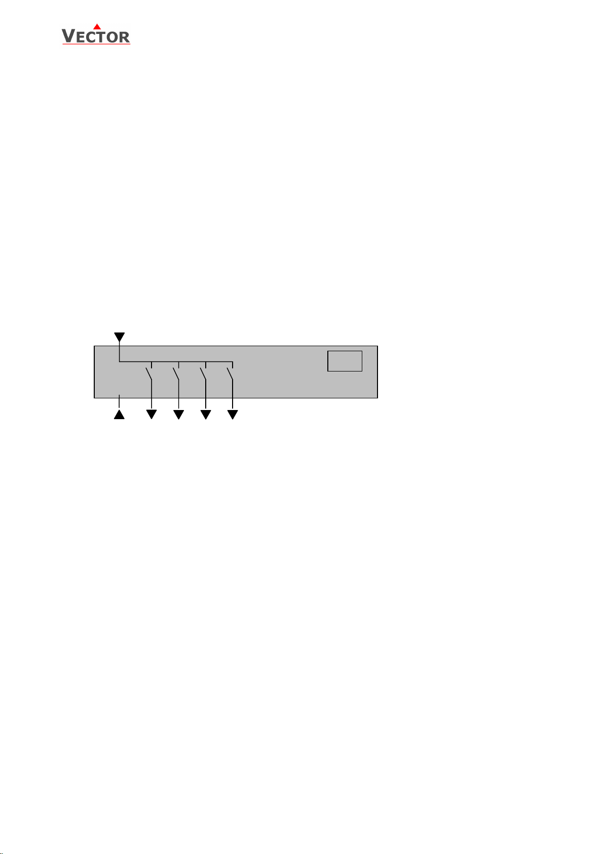
Wiring Diagram
Description:
N Power supply: 0V Neutral
L Power supply: 230VAC
Y1 Binary output 230V AC: Fan speed low
Y2 Binary output 230V AC: Fan speed medium
Y3 Binary output 230V AC: Fan speed high
Y4 Binary output 230V AC: Valve (Heating or cooling)
Doc: 70-00-0198, V3.0 Date: 20120403 © Vector Controls GmbH, Switzerland Page 3
Subject to alteration
Page 4

TLC3-FCR Engineering Manual
Operation mode
Comfort (occupied)
All control functions operating per set points.
Economy (unoccupied):
Set points shifted according to Parameters FC04.
Economy mode and setpoint shift may be disabled with UP06
OFF
Energy Hold Off
Outputs are off, inputs monitored for alarm condition
Heating
Output activates if temperature lower than setpoint
Cooling
Output activates if temperature higher than setpoint
Fan
Fan is running, the vertical bars show active speed 1-3
Manual mode
Manual override of fan speed, fan only mode or override of time schedule active.
Schedule
Deluxe only: Time schedule is active
Left (POWER):
Press < 2 sec.: Toggle Economy Comfort mode or switch from OFF
to ON
Press > 2 sec.: Turn unit OFF. Text
OFF displayed with current time
(deluxe) temperature (standard)
(Parameter setting: Return to
previous level. ESC)
Up :
Increase setpoint
(Parameter setting:
scroll menu options
and parameters)
Down:
Decrease setpoint
(Parameter setting: scroll menu
options and parameters)
Mode
Display of operation
mode
Large Digits
Display of input or parameter value.
Vertical Bar
(fan speeds 1-3 or proportional
output in 10% steps)
Small Digits
Display of setpoint, clock or
parameter number.
Right (OPTION)
Press < 2 sec.: Select fan speed:
Low, medium, high or auto
Press > 2 sec.: Manual H/C change
(Parameter setting: ENTER to
select menu option, accept
parameter change)
Display and Operation
Power Failure
All the parameters and set points are memorized and do not need to be reentered. Depending on UP05 the unit will
remain switched off, switch on automatically or return to the operation mode it was in before the power failure.
Deluxe version only: Timer operation and daytime setting will be retained for 24h. The controller has to be connected
to a power supply for at least 10 hours for the backup function to operate accordingly.
Frost Protection
The controller will enter frost protection mode if the room temperature drops below 5°C (41°F). All heating outputs will
be fully opened. Frost protection mode will be left once the temperature reaches 10°C (50°F). Frost protection display
will remain until a button is pressed. Frost protection can be enabled/disabled using user parameter UP-09
Error messages
Following error condition may be shown:
Err1: The temperature sensor is damaged.
FP: Steady: Frost protection is active.
Doc: 70-00-0198, V3.0 Date: 20120403 © Vector Controls GmbH, Switzerland Page 4
Subject to alteration
Blinking: Frost protection activated in the past and is now inactive. Confirm with OPTION key.
Page 5

TLC3-FCR Engineering Manual
For standard models: Press OPTION > 2 sec. SEL and H-C is displayed.
For deluxe models: Press OPTION > 2 sec. SEL and current time is displayed.
Press UP key twice. SEL and H-C is displayed.
Press OPTION again to toggle Heating, Cooling and Fan only modes.
SEL
H-C
Press OPTION > 2 sec. SEL and current time displayed
Press OPTION < 2 sec. to change time,
Minutes blink: UP/DOWN to changes, OPTION to save,
Hours blink: UP/DOWN to changes, OPTION to save,
Press OPTION to save time,
DAY1 blinks: UP/DOWN to change, OPTION to save
SEL
00:00
DAY1 (Mon)
Press OPTION > 2 sec. SEL and current time displayed
Press UP:
SEL and PRO displayed, clock symbol blinks
Press OPTION:
PRO1 shows with 1 blinking. UP/DOWN select time schedule group
Press OPTION
OFF/ ON blinks, UP/DOWN to change, OPTION to save
SEL
PRO
Pro1-Pro4
OFF/ON
This time schedule will be active during the selected weekdays
Press UP/DOWN to step through available options:
d1-7, d1-6, d1-5, d6-7, day1, day2, day3, day4, day5, day6, day7
Day 1 stands for Monday, day 2 for Tuesday and so forth
Press OPTION to save day selection
Pro1
d1-7
One bar on the right side indicates the first switching event
Press UP/DOWN to select action for first switching event:
No = switching event not active
OFF = switches unit off, Reset (UP17) active if switched to ON manually.
Eco = sets operation mode to On and Economy (Not occupied),
reset (UP17) active if set to comfort manually
On = sets operation mode to On and Comfort (Occupied)
Uni = University mode, Reset (UP17) not active if manually activated
Press OPTION to select switching time of first event
Pr01
no
Press UP/DOWN to select switching time:
Select switching time 00:00 to 23:45 in 15-minute steps
Press OPTION to complete and select action of second switching event
Pr01
08:00
Repeat Step 3 and Step 4 for the remaining switching events.
If a switching event is not needed, set it to “no”
The bars on the right side indicate number of switching event
After completing the 4th switching event, the process returns to the selection of the time schedule on step 1.
Pr01
08:00
Manual heat – cool change
To manually change heating or cooling mode press the OPTION key for more than 2 seconds. Access to manual heat –
cool change may be disabled by parameters.
Clock operation
The deluxe model contains a quartz clock with battery back-up. Up to 4 time schedules with each 4 mode changes
based on time and day of the week may be programmed. A blinking clock indicates that the time has not been set or if
the unit was without power for longer than 48 hours. The time needs to be set to allow time schedules to operate.
Clock setup
Creating time schedules
Step 1: Selection and enabling of time schedules
Step 2: Select weekdays
Step 3: Selected action of first switching event
Step 4: Selected time of first switching event
Step 5: Select actions and time of switching event 2 - 4
UNI: University mode: This switching mode is used for rooms such as lecture rooms and auditoriums that might
be occupied during a certain time. During this time the reset is not active. The unit will not start itself when UNI
mode is active. It still needs to be manually activated. This is to avoid unnecessary heating or cooling of such
rooms while they are not occupied.
A blinking clock indicates that the time needs to be set. Time programs will not operate if the time is not defined.
See chapter operation, advanced settings for instructions on how to set the time.
Access to time schedules may be disabled with UP-04
Doc: 70-00-0198, V3.0 Date: 20120403 © Vector Controls GmbH, Switzerland Page 5
Subject to alteration
Page 6

TLC3-FCR Engineering Manual
11
Operation with OPR-1
The deluxe version may be alternatively operated with an infrared remote
controller.
1. Mode indication, Auto, Dry, Cool, Fan, Heat
2. 2-digit display of setpoint
3. Fan indication
4. 4-digit display of current time or delayed switching time
5. Economy button: Toggles Economy/Comfort mode
6. Mode button, changes operation modes
7. UP/DOWN Button: Set point adjustment buttons
8. FAN Button: Changes fan speed, low – medium – high or Auto
9. Boost button, activates full output for 5 Minutes
10. Time related buttons: Timer, Hour, Minute
11. POWER Button: Operation mode ON – OFF
Switching ON
The unit is switched on by pressing the POWER button. It will start up in comfort
mode.
Changing between COMFORT and ECONOMY
Pressing the SLEEP button toggles between ECONOMY and COMFORT modes.
Switching OFF
Pressing the POWER while the unit is on, will switch the unit off. The current time will be displayed in the LCD of OPR-1.
Changing of set points
Only the set points for the temperature loop may be changed. Set point range is 15 to 30 °C.
Changing of fan speeds
Repeatedly pressing the fan speed button steps through low, medium, high and automatic fan speeds. Automatic fan
speed will not be activated in FAN ONLY mode.
Boost
Pressing the boost button activates a 5 minute boost. The output will be fully opened for the period of 5 minutes
independent of demand. This may be used to change stale air during a meeting break or when entering the room.
Clock settings
The remote controller contains a daytime clock. In order to set the clock, press HOUR and MINUTE button together
until the clock starts blinking. Then set the correct time with the HOUR and MINUTE buttons. Confirm by pressing the
TIMER button. The clock of the OPR will set the clock of the controller.
Delayed switching
The unit may be delayed switched on or off using the timer button. Pressing the timer button once will display Timer
ON if currently in OFF mode or TIMER OFF if currently in ON mode. Set the time when the unit is supposed to switch
on or off using the HOUR and MINUTE buttons.
Mode changes
Repeatedly pressing the mode button may activate the following operation modes: HEAT, COOL and FAN ONLY. The
mode change may be disabled using the UP parameters.
Note:
The remote controller is currently only available in °C mode.
Doc: 70-00-0198, V3.0 Date: 20120403 © Vector Controls GmbH, Switzerland Page 6
Subject to alteration
Page 7

TLC3-FCR Engineering Manual
Parameter
Description
Range
Standard
UP 00
Enable change of operation modes
ON, OFF
ON (Enabled)
UP 01
Enable change of set points
ON, OFF
ON (Enabled)
UP 02
Enable manual control of fan speeds
ON, OFF
ON (Enabled)
UP 03
Enable change of heating/cooling mode
ON, OFF
W00: ON (Enabled)
W01: OFF
(Disabled)
UP 04
Enable access to Time programs
ON, OFF
ON (Enabled)
UP 05
State after power failure:
0 = Switched OFF, 1 = Switched ON, 2 = state before power failure
0, 1, 2
2
UP 06
Enable Economy (unoccupied) Mode.
Shift the set point to a lower temperature in winter or higher temperature
in summer in order to save energy. Economy mode may be activated
through the POWER button, or with the external input (typically for key
card switches in hotel rooms or motion detectors for meeting rooms.)
ON, OFF
ON (Economy )
UP 07
Celsius or Fahrenheit, Select ON for Fahrenheit, OFF for Celsius
ON, OFF
OFF (Celsius)
UP 08
Calibration value of temperature sensor . This value is calibrated at
manufacturing of the thermostat. If required it is possible to shift the
temperature –10° to +10° in 0.1° K steps.
-10…10
0
UP 09
Enable Frost Protection.
Activates the output independent of operation mode when the control
temperature drops below 5°C or 41°F. The controller returns to normal
operation when the temperature increases above 10°C or 50°F.
ON, OFF
W00 = ON
(Frost Protection)
W01 = OFF
(No Frost Protection)
UP 10
Select contents of Large LCD display in standard mode:
00 = OFF
01 = Setpoint
02 = Temperature Sensor
03 = Output Fan Speed
04 = Clock
0…4
02
Temperature
UP 11
Select contents of small LCD display in standard mode
(use table of UP 10)
0…4
04 Deluxe:
show clock
01 Standard:
show setpoint
UP 12
Contents of vertical bar in standard mode
OFF = Fan Speed
ON = Control output
ON, OFF
OFF (FAN)
UP 13
Deluxe only
Clock display type:
OFF = Show 24hour clock
ON = Show 12hour clock (AM, PM)
ON, OFF
OFF (24h)
UP 14
Deluxe only
Reset: applies when the unit is manually switched on, while in scheduled
off mode. The unit will switch automatically back to the scheduled mode
when the reset time expires.
0 = Reset of override mode is not active.
1…255 = delay in minutes to switch off device
0…255
60 (Min)
Setting of parameters
The TLC3-FCR is an intelligent controller and can be adapted to fit perfectly into your fan coil application. The control
operation is defined by parameters. The parameters are set during operation by using the standard operation terminal.
The parameters are password protected. There are two levels of parameters: User operation parameters for access
control settings and Expert parameters for control functions and unit setup. The passwords for user levels and expert
levels are different. Only control experts should be given the control parameter password.
The parameters can be changed as follows:
1. Press UP and DOWN button simultaneously for three seconds. The display will indicate the firmware version in
the upper large digits and the revision in the lower small digits. Pressing any key will show: CODE.
2. Select a password using UP or DOWN buttons. Select 009 in order to get access to the user parameters, 241
for controls parameters.
Press OPTION after selecting the correct password.
3. Once logged in, the parameter is displayed immediately
4. Select the parameters with the UP/DOWN keys. Change a parameter by pressing the OPTION key. The MIN
and MAX symbols show up and indicate that the parameter may be modified now. Use UP and DOWN key to
adjust the value.
5. After you are done, press OPTION or POWER in order to return to the parameter selection level.
6. Press the POWER key again so as to leave the menu. The unit will return to normal operation if no key is
pressed for more than 5 minutes.
User Parameters
Doc: 70-00-0198, V3.0 Date: 20120403 © Vector Controls GmbH, Switzerland Page 7
Subject to alteration
Page 8

TLC3-FCR Engineering Manual
Parameter
Description
Range
Standard
FC 00
Minimum set point limit in heating mode
-40…60°C (160°F)
16°C (61°F)
FC 01
Maximum set point limit in heating mode
-40…60°C (160°F)
24°C (75°F)
FC 02
Minimum set point limit in cooling mode
-40…60°C (160°F)
18°C (64°F)
FC 03
Maximum set point limit in cooling mode
-40…60°C (160°F)
30°C (86°F)
FC 04
Economy (unoccupied) Mode temperature shift:
The comfort (occupied) setpoint is shifted by the value set with
parameter. If heating is active the comfort setpoint will be
decreased, if cooling is active, the setpoint will be increased.
(Enable with UP06.)
0…10.0°C (20.0°F)
5.0°C (10°F)
FC 05
Switching Span Heating,
Setting this value to 0 disables the auto fan speed function in
heating mode
0…10.0°C (20.0°F)
1.5°C (3°F)
FC 06
Switching Span Cooling
Setting this value to 0 disables the auto fan speed function in
cooling mode
0…10.0°C (20.0°F)
1.0°C (2°F)
FC 07
Switching Hysteresis is the difference between switching
on and switching off. A small hysteresis will increase the
number of switching cycles and thus the wear on fan
and relays contacts.
0…10.0°C (20.0°F)
0.5°C (1°F)
FC 08
Mold Protection:
In mold protection, the fan keeps running independent
of temperature as long as the unit is switched on.
ON, OFF
OFF
FC 09
Delay OFF (Minimum running time)
0…255 s
10s
FC 10
Delay ON (Minimum stopping time)
0…255 s
10s
FC 11
Control option:
0 = Cooling only
1 = Heating only
2 = 2-pipe system
0…2
-W1: = 0
-W2: = 1
Default: = 2
FC 12
P – band heating XPH
0-10.0°C (20.0°F)
2.0°C (4.0°F)
FC 13
P – band cooling XPC
0-10.0°C (20.0°F)
2.0°C (4.0°F)
FC 14
PWM cycle time heating, 0 disables PWM mode
0…100 min
0
FC 15
PWM cycle time cooling, 0 disables PWM mode
0…100 min
0
Control configuration
Identifying the firmware version
The parameters and functionality of controller depend on its firmware revision. It is therefore important to use a
matching product version and parameter set. The firmware version is shown on the large LCD digits when pressing UP
and DOWN buttons for more than 3 seconds simultaneously.
Control Parameters (Access code: 241)
Warning! Only experts should change these settings! See user parameters for login procedure.
Controls configuration
Control Configuration for PWM – 3-point floating mode
Proportional control (P-band)
The proportional control function calculates the output based on the difference between setpoint and measured value.
The proportional band (P-band) defines the difference between setpoint and measured value which will result in a 100%
output. Setting the proportional band to 0 disables proportional control.
Output configuration
Pulse With Modulation (PWM)
In PWM mode the digital output will be switched on/off once per cycle. The on and off times are calculated according
to the control sequence. It is not recommended to use cycle times below 10 minutes as the lifetime of the relays will
be shortened with frequent switching. For PWM applications requiring cycle times below 100 seconds we recommend
using TLC3-FCR-2 with TRIAC outputs
Doc: 70-00-0198, V3.0 Date: 20120403 © Vector Controls GmbH, Switzerland Page 8
Subject to alteration
 Loading...