

Page 1
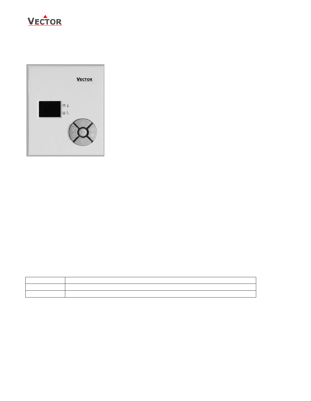
PI Thermostat TEF
TEF
PI Controller and Thermostat
Features
• Controller: Floating point temperature controller and positioner
• On/Off thermostat for 4-pipe or 2-pipe systems with fan function.
• Temperature control depending on room or return air temperature
• Integrated room temperature sensor
• Programmable user and control parameters
• Minimum, maximum set point limitation
• Enable/Disable change of set points and heating/cooling changeover
• Temperature display in Celsius or Fahrenheit
• Selectable Frost protection
• Operating Voltage 24V
Applications
• Individual PI-control of the temperature in rooms that are heated or cooled with 2-pipe systems or 4pipe systems using spring return fan coil valves.
• Cost efficient control of pressure dependent VAV units.
• Positioning of an on/off actuator by using the running time of the actuator
• Controlling the temperature output of a simple air-handling unit with one heating or cooling coil.
• Radiator or floor heating, cooling ceiling.
General Description
The TEF is a stand-alone electronic temperature controller with one PI control loop. It features 1 PI sequence
and 2 binary sequences. The TEF features 1 NTC temperature sensor input. One additional function is the
manual positioning of a floating actuator.
The TEF features 2 binary outputs (Relays). A detailed parameterization is possible with the use of a simple
configuration routine. The TEF can be configured using the standard operation terminal. No special tools or
software is required.
Ordering
Item Name Description/Option
TEF Compact PI controller 1 TI internal & external, 2 DO (Relays)
TEM Compact PI controller 1AI, 1 TI int & ext, 1 AO
Selection of actuators and sensors
Temperature Sensors: Use only our approved NTC sensors to achieve maximum accuracy. Recommended is
SDA-Tn10-20 as Duct sensor, SRA-Tn10 as Room sensor and SPA-Tn10-10 as immersion sensor.
Floating Actuators: Any actuators with less than 250 VAC, 100W are acceptable. Actuators with constant
running time are preferred for optimum functionality.
Binary auxiliary devices: E.g. pumps, fans, on/off valves, humidifiers, etc. Do not directly connect devices that
exceed 250 VAC, 100W.
V1.3a, 20100504 © Vector Controls GmbH, Switzerland Page 1/8
Subject to alteration
Page 2
PI Thermostat TEF
37
5
Technical Specification
Power Power Supply 21.5 - 26.5 V AC 50/60 Hz
Power Consumption Max 2 VA
Electrical Connection Terminal Connectors
Output Signal
Temperature Sensor NTC resistor 10kΩ at 25 °C
Maximum allowed cable length with
Operation Control Temperature Range
Display precision 0.5 °K
Environment Operation
Transport & Storage
Ambient Humidity 0 to 95% rH No n Condensing
Standards conform according to
Product standards
Pollution Class Normal
Degree of Protection IP30 to EN 60 529
Safety Class III to EN 60 730
General Housing ABS plastic
Servicing Maintenance Free
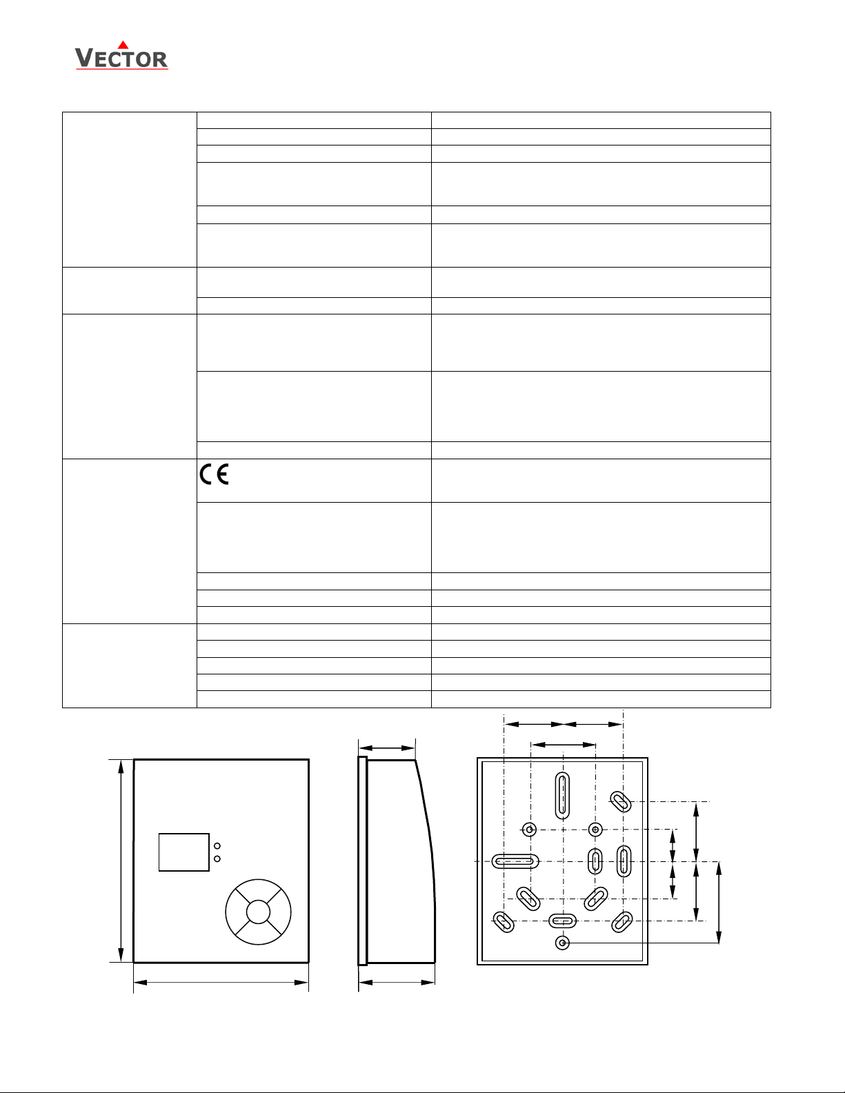
Dimensions 105 x 90 x 37 mm (H x W x D)
Dimensions of package 160 x 100 x 40 mm (H x W x D)
Weight (including package) 215 g
Switching medium
Maximum Load
2
copper cable 1.5 mm
connections
Measured Temperature Range
Climatic Conditions
Temperature
Humidity
Climatic Conditions
Temperature
Humidity
Mechanical Conditions
EMC Standard 89/336/EEC
EMEI Standard 73/23/EEC
Automatic electrical controls for
household and similar use
Special requirement on
temperature dependent controls
for external
Dimensions
2
2 digital outputs,
Relays contacts
1A, 24V DC
80 m
10 to 35 °C (50…95 °F)
10 to 35 °C (50…94 °F)
To IEC 721-3-3
class 3 K5
0…50°C
<95% r.h.
To IEC 721-3-2 and IEC 721-3-1
class 3 K3 and class 1 K3
-25…70°C
<95% r.h.
class 2M2
EN 61 000-6-1/ EN 61 000-6-3
EN 60 730 –1
EN60 730 – 2 – 9
28
28
36
28 28
18
105
18
40
90
V1.3a, 20100504 © Vector Controls GmbH, Switzerland Page 2/8
Subject to alteration
Page 3
PI Thermostat TEF
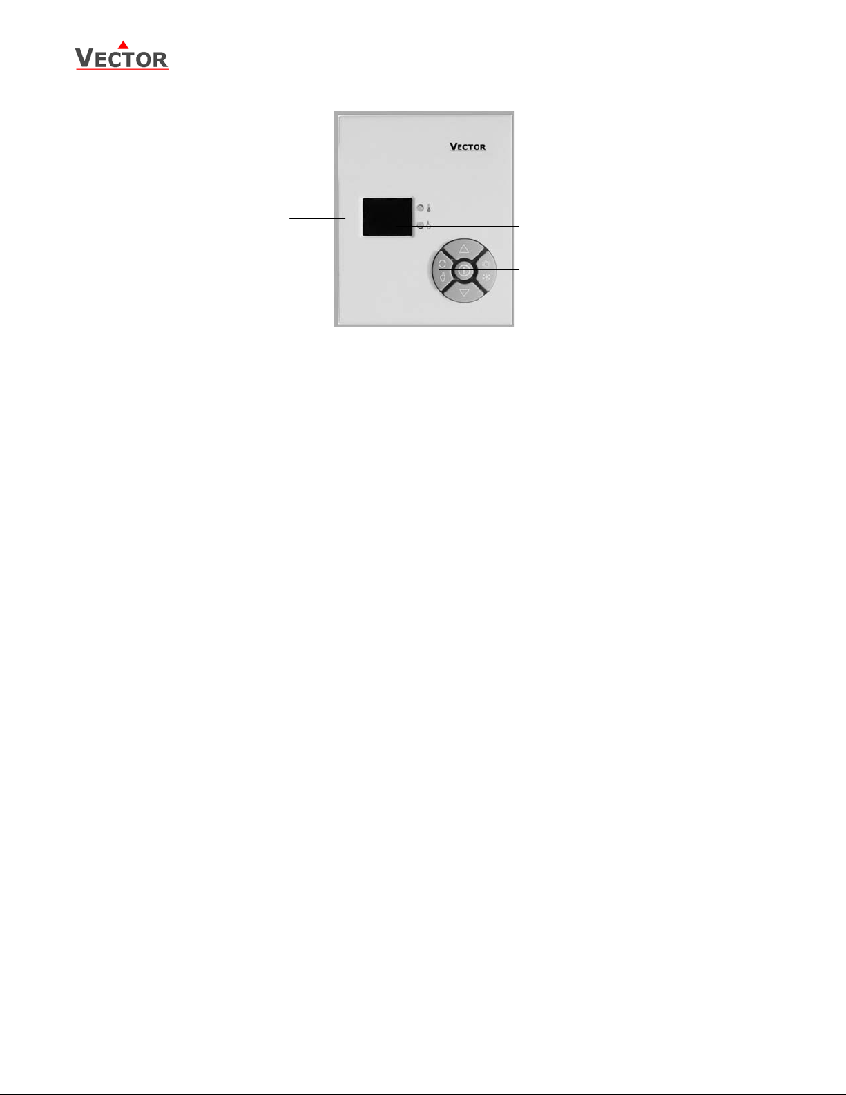
Display and Operation
Legend
1. Status LED for temperature control mode. Green = Cooling, Red = Heating,
Orange = setpoint or parameter menu active.
2. Status LED for analog control mode. Green = Input is equal to setpoint, Red = Input is not equal to
setpoint, Orange = setpoint or parameter menu active.
3. Buttons for operating the unit:
☼ POWER button, switches the controller on or off
UV UP and DOWN buttons, change setpoints and parameters.
T LEFT button, Activates analog control mode or
acts as ESC if in parameter menu.
RIGHT button, Activates temperature control mode, Heat / Cool change or
acts as ENTER if in parameter menu
4. Numerical LED display with 2 digits. Indication of current value or setpoint
Display
The TEF controller features a two digit number display and two dual colors status-LED.
Power Failure
All the parameters and set points are memorized and will not have to be reentered. The unit will return to the
operation mode it was in before the power failure. I required the unit would perform a reset cycle after
resuming of power supply. A reset is necessary if the unit was in operation during power failure. The actuator
position would then be lost and has to be regenerated. The controller assumes it is in the fully open position at
the return of power, completely close the actuator and then return to the mode of operation and setpoint it was
in before the power failure.
Frost Protection
The controller will activate if the temperature drops below 10°C (50°F). It will control the environmental
temperature up to 15° C (59° F) and then return to its previous mode. The LED will show FP and the status LED
blink alternating. Frost protection can be enabled/disabled using user parameter P7
Using an External Sensor
In order to utilize the external sensor, the internal sensor needs to be cut. The internal sensor is located in the
lower middle section of the PCB. It is marked with RT. It is recommended to cut one leg with a cutting tool and
bend the sensor to the side.
Calibrating the sensor
If the room temperature displayed does not agree with the room temperature effectively measured, the
temperature sensor can be recalibrated by adjusting user parameter P8. There is as well a potentiometer
located in the lower middle section on the PCB. Adjusting this will alter the temperature as well.
V1.3a, 20100504 © Vector Controls GmbH, Switzerland Page 3/8
Subject to alteration
Page 4

PI Thermostat TEF
Operation
1. Switching ON
The unit is switched on by pressing the POWER button. It will start up in its previous mode.
2. Temperature Control
Press the RIGHT button once to activate temperature control mode if in analog mode. The temperature set
point is indicated by pressing the UP or DOWN key once. The set point will be changed, if either one of this
keys is pressed again within 4 seconds.
3. Positioner, Fan activation
Press the LEFT button while in temperature mode to activate the positioner.
In case fan control is enabled in 2-position mode, pressing the left key will override automatic fan control.
4. Switching OFF
The unit is switched off by pressing the POWER button once.
5. Changing HEATING/COOLING mode.
Pressing the Auto button for more than 3 seconds will change the temperature control mode. (In case both
modes are enabled, See P4). In case 4-pipe system is enabled, it is not required to switch between heating
and cooling.
The mode of the unit is indicated by the upper status LED. Green is for cooling and red is for heating.
Setting of parameters
A number of parameters can be set in order to optimize the control performance and adapt the unit to various
applications. These parameters can be set during operation without opening the unit.
The parameters are password protected in order to avoid unauthorized tampering. There are two levels of
parameters: User parameters P0-P10 and Expert control parameters E0 – E7. The passwords for user levels and
expert levels are different. Only control experts should be given the control parameter password.
The parameters can be changed as follows:
1. Press LEFT and RIGHT button together for three seconds. The display will indicate PP and both status
LED’s are blinking in orange.
2. Select a password using UP or DOWN buttons. Dial 09 in order to get access to the user parameters.
The RIGHT key will work as ENTER key and the LEFT key as ESC key. Press Enter after selecting 09.
3. Once logged in, PO is displayed and the two status LEDs show a steady orange light. Now you can
select the parameters by pressing the up or down key.
4. Change a parameter by pressing the RIGHT key. The two status LEDs will now blink alternatively in
orange color. Change the parameter using UP or DOWN keys.
5. After you are done, press RIGHT again in order to return to the parameter selection level. In order to
leave the menu press the POWER key once or do not press a key for more than 10 sec.
User Parameters
Parameter Description Range Factory
P0 Celsius or Fahrenheit C, F C
P1 Light intensity of display, 1 = dark, 10 = bright 1…10 10
P2 Enable control modes
1 = Temperature only, 2 = Positioner only,
3 = Both modes are enabled
P3 Choose if the end user is allowed to change set points
0 = Disabled,
1 = Enable set point access for temperature loop,
2 = Enable set point access for positioner
3 = Enable set point access for both loops
P4 Heat/Cool change Enable, Choose if the end user is
allowed to change heating/cooling mo de
0 = Disabled, 1 Enabled
P5 Dead zone span.
Difference between heating & cooling set point
P6 Minimum set point limit 10…33/50…97 10C, 50F
P7 Maximum set point limit 11…34/51…98 34C, 98F
P8 Frost protection enable/disable no, FP FP
P9 Calibration value of temperature. This value is calibrated
at manufacturing of the thermostat. If required it is
possible to shift the temperature –3° to +3° in 0 .5 ° K
steps.
PA Display in analog mode, 0 = 0-10, 1 = 0-100 0,1 0
1,2,3 3
0, 1, 2, 3 3
0,1 1
0…10 K 1 K
-3…3 ~
V1.3a, 20100504 © Vector Controls GmbH, Switzerland Page 4/8
Subject to alteration
Page 5

PI Thermostat TEF
T
Tn
Control Function
Temperature Control Mode: PI Control E2=0
The controller reads the temperature either by using its integrated temperature sensor or by using an external
sensor. The controller maintains the temperature set point by calculating the position of the actuator using a 3point modulating signal. The on/off actuator is positioned based on its opening and closing time. The
temperature is controlled using a PI control function. If both P and I parts are enabled, they will be added
together to calculate the output position. Following control parameters decide the function of the PI loop:
• E3: P-band in °K. The p-band corresponds to the temperature difference of current value to setpoint,
which is required for fully opening the output.
• E4: A large I part increases the swinging tendency of the control loop. Limiting the integral part may
reduce this tendency. The I-part is disabled if 0 is selected.
• E5: Tn, Reset time of Analog loop integral. Tn is the time needed for the integral to run from 0 to 100%.
The range is 0.5 - 30 min. The setting very much depends on the application it is used for. For
temperature control of a medium sized room, a setting of 5 minutes should be appropriate.
• P5: Dead Zone Span. The cooling setpoint W
Changing the cooling setpoint therefore changes as well the heating setpoint. The factory setting for the
dead zone span is 1K.
Heating Mode P Control Part Cooling Mode
YT [%]
100
WH
XDZ
WC
Xp
Setpoint Heating
H
C
0
T Room Temperature w
Xp E3: Proportional Band w
Y
Output signal of temperature loop XDZ P5: Dead Zone Span
T
Tn E5: Integral Reset Time
Xp
consists of the heating setpoint and the dead zone span.
C
I Control Part
Y
[%]
T
W
100
[°C]
Setpoint Cooling
H/C
0
t [min]
Switching frequency
The TEF works with two digital outputs to modulate a floating actuator. The position of the actuator is calculated
with above described PI algorithm. The controller moves the actuator to the calculated position by either
opening or closing the actuator. The actuator should not be moved for every little change in position, since this
would reduce the lifetime of the actuator. We differentiate if we are moving the actuator in the same direction
as the previous move or if we reverse direction.
• E7: Switching difference: For example the last actuator movement was opening and we open again. The
actuator will only move, if the difference to the current actuator position is larger than this parameter.
• E6: Reversing difference: For example the last actuator movement was opening and we want to close
now. The actuator will only move, if the difference to the current actuator position is larger than this
parameter.
Below are examples of switching and reversing difference after the actuator has been opening on its
previous move.
Switching Difference
YT [%]
100
1
0
2
SD
XT[%]
XT Calculated actuator position RD E6: Reversing Difference
Y
Actual actuator position 1 Opening up to step 1
T
SD E7: Switching Difference 2 Actuator acting point
Reversing Difference
Y
[%]
T
100
2
0
1
RD
XT[%]
V1.3a, 20100504 © Vector Controls GmbH, Switzerland Page 5/8
Subject to alteration
Page 6

PI Thermostat TEF
T
Temperature Control Mode: On/Off control E2=1
On/Off control can be used to operate fan coil valves, reheat or cooling compressor stages.
Outputs used are D OUT 1 for heating, D OUT 2 for cooling.
Control functions:
• E3: The hysteresis defines when an output is switched on and off again. The aim is to avoid
unnecessary switching and thus increasing the life span of involved equipment as well as saving energy.
Factory setting is 2 K.
• E6: Enable 4-pipe system. Using a 4-pipe system, both heating and cooling valves are present. It is not
necessary to switch between heating and cooling mode.
• E7: Fan control: In 2-pipe mode it is possible to control a fan. The fan will run if heating or cooling is
required, in auto mode it will stop when the measured temperature reaches the setpoint. The fan can be
operated even the setpoint is reached by using the LEFT key to activate fan operation in idle mode.
• P5: Dead Zone Span. The cooling setpoint W
Changing the cooling setpoint in 2-pipe mode therefore changes as well the heating setpoint. The
factory setting for the dead zone span is 1K.
Y
[%]
H,C
T Room Temperature w
H
RC
XDZ P5: Dead Zone Span
100%
E3: Hysteresis Heating/Cooling wC Setpoint Cooling = WH + X
Heating Cooling
WC
HRC
WH
XDZ
0
Setpoint Heating
H
consists of the heating setpoint and the dead zone span.
C
[K]
DZ
Analog Control Mode: Positioner
The positioner mode only operates, if the unit is set to PI control mode (E2 = 0).
While programmed to work as positioner the controller will move the actuator to the setpoint position. The
on/off actuator is positioned based on its opening and closing time. The setpoi nt can either be a percentage
from 0…100% or a step signal from 0…10. (See parameter P10 for details.)
Temperature Control Mode:
The upper status LED lights up red for heating, green for cooling. The number display shows the room
temperature. The point in the lower right corner of the display will indicate 0.5-degree steps. The setpoint is
displayed for 5 seconds if either UP or DOWN buttons are pressed once.
Analog Mode: Positioner
The lower status LED serves as indication for the analog loop. It lights up green if the input matches the
setpoint and red if the input is off target. Pressing UP or DOWN key will display the setpoint. The setpoint is,
depending on parameter P10, a value either from 0…10 or 0…100. Since the display has only 2 digits, 100 is
indicated as A0.
V1.3a, 20100504 © Vector Controls GmbH, Switzerland Page 6/8
Subject to alteration
Page 7

PI Thermostat TEF
Setting of control parameters
Warning! Only experts should change these settings!
The password for the expert user is 14. See setting for user parameters for login details.
Expert Description Display Standard
E0 Actuator running time Opening, 10…990 seconds 01 - 99 10
E1 Actuator running time Closing, 10…990 seconds 01 – 99 10
E2 Control mode
0 = PI control, 1 =On/Off control
E3 P – Band / Hysteresis Temperature loop, Select the
accuracy of the temperature loop in degrees Kelvin.
E4 Maximum of I part of Analog Loop, Limits the influence of
the integral part on the output signal. 0 disables the I part
E5 Tn, Reset time of Analog loop integral, 0.5 - 30 min 0.5…30 02
E6 For on/off control only: 2 pipe or 4 pipe system
0 = 2 pipe system, 1 = 4 pipe system
E7 For 2-pipe systems only: Enable Fan Control
0 = No Fan control, 1 = Fan Control
E8 Reversing Difference in percentage of actuator position 00…A0 (100) 10
E9 Switching Difference in percentage of actuator position 00…A0 (100) 5
Mechanical Design
The unit consists of three parts:
• The base unit, which contains the terminal connecters, temperature sensors and control logic
• The front plate, which holds the buttons
• The base plate, to ease installation
0, 1 0
0.5…8.0 2.0
0.0…A0 (100) 0.0
0, 1 0
0, 1 0
Mounting location
• On an easy accessible interior wall, approx.
1.5 m above the floor in an area of average temperature.
• Avoid direct sunlight or other heat sources, e.g. the area above radiators and heat emitting electrical
equipment.
• Avoid locations behind doors, outside walls and below or above air discharge grills and diffusers.
• Location of mounting is less critical if external temperature sensors are used.
Installation
1. Install the mounting plate on the wall box. The type
of screws required depends on the wall box. For
Chinese standard M4x25 screws are most suitable.
The mounting plate provides holes for most
international standards. Horizontal distance of
mounting screws ranges from 35 to 65 mm; vertical
distances are 58 to 85 mm.
2. On the upper side of the controller, there are two
clips. Press them inside using a small screwdriver.
3. Separate the front plate of the controller with the
base by opening it carefully. Unplug the connector
from the button.
4. Connect the wirings as shown in the diagram below.
Pay attention to follow local guidelines regarding
insulation and wire sizes.
5. Connect the main body to the mounting plate by
holding it in place and inserting the two small
screws that are part of the package in the upper left
and lower right corner.
6. Reconnect the plug of the button and press the
front plate into place. Insert the lower part first and
then press down the upper part until hearing a click.
V1.3a, 20100504 © Vector Controls GmbH, Switzerland Page 7/8
Subject to alteration
Page 8

PI Thermostat TEF
Connection terminals
Actuator 24 V
AC/DC
Open/Close
⊥
1 2 3
Power Supply
AC/DC 24V
1 2 3
GND 24V 24V
Ground
5 4
GND 24 V
AC/DC
DO1 / OPEN
DO2 / CLOSE
RT = Internal Temp
Connection Diagram
24V DC +
24V AC ~
24V DC 24V AC ⊥
5 6 7
4
External
temperature
sensor
6 7
Ext Temp
T-EF
RT
EXT
1 2 3
YM
Legend:
1. Signal Ground (= 4)
2. Open Signal 24V AC or DC (= 5)
Digital Output 1
3. Close Signal 24V AC or DC (= 5)
Digital Output 2
4. Power Supply Ground
5. Power supply 24 V AC/DC
6. External temperature Sensor
7. External temperature Sensor
In order to activate External sensor,
RT must be cut.
Legend:
RT
External temperature sensor
EXT
Actuator
Y
M
TEF
V1.3a, 20100504 © Vector Controls GmbH, Switzerland Page 8/8
Subject to alteration
 Loading...