

Vector TDC-BH-U-W20, TDC-BH-U-W24, TDC-BH-U-W25, TDC-BH-U-D-W24, TDC-BH-U-D-W20 Operation Manuals
...Page 1
Duct humidistat TDC-BH-U-W24
Duct humidistat TDC-BH-U-W24
Duct humidistat TDC-BH-U-W24
Doc: 70-07-0114B-24, V1.4, 20160912 © Vector Controls GmbH, Switzerland Subject to alterations
TDC-BH-U Intelligent duct humidistat
General description
The TDC-BH-U is a stand-alone electronic binary humidity stat. The TDC-BH-U features one duct humidity
sensor, one external NTC temperature sensor input and two binary outputs (Relays).
A detailed parameterization is possible with the use of a simple configuration routine. The TDC-BH-U can be
configured using the standard operation terminal. No special tools or software is required.
Ordering, Name convention
TDC-BH-U
│ ││ └───── Housing: U = Conduit connector, Blank: Cable gland
│ │└─────── Function H = Humidity
│ └──────── Output: B = Binary
└──────────Series Indication TDC
Item name
Item code
Variant
Features
TDC-BH-U-W20
TDC-BH-U-W24
TDC-BH-U-W25
40-10 0059-20
40-10 0059-24
40-10 0059-25
standard
humidifying
de-humidifying
Binary controller with:
1 Internal humidity input
1 external temperature input (For set point
shift)
1 DO (Relay) for humidifier or dehumidifier
1 DO (Relay) for fan (optional)
TDC-BH-U-D-W20
TDC-BH-U-D-W24
TDC-BH-U-D-W25
40-10 0060-20
40-10 0060-24
40-10 0060-25
Deluxe
humidifying
de-humidifying
Accessories
SOD-Tn10-1
AES3-HT-A5
40-20 0108
40-50 0104
Outdoor sensor
Replacement humidity sensor 5% accuracy
Selection of actuators and sensors
External temperature sensors: Use only our approved NTC sensors to achieve maximum accuracy.
Recommended is SDB-Tn10-15 as Duct sensor and SOA-Tn10 as outdoor sensor.
Binary auxiliary devices: E.g. humidifiers, de-humidifiers and fans. Do not directly connect devices that
exceed 2(1.2) A. Observe startup current on inductive loads!
Mounting location
The Duct controller should be installed directly on the duct, in an area where the air stream is well mixed:
Locate a supply air sensor two or three meters downstream from the nearest fan and coil.
Mount the return air sensor close to the air inlet but downstream from a return fan if one is present.
Installation
1. Drill a hole with a diameter of 16 mm (5/8”) in the air duct.
2. Connect the wires to be connected to the terminals of the back part according to wiring
diagram.
3. Insert the probe in the hole; secure the back part to the duct with two –self-tapping screws.
4. Connect the cable of the operating unit to the matching connector on the back part.
5. Slide the two latches located on the left side of the front part into the hooks at the upper left
side of the back part.
6. Carefully lower the front part until the interconnector reaches the back part. Continue
pressing in a gentle way until the front part is fully connected.
7. With a Philips-type screw driver of size #2, carefully tighten the front holding screw to secure
the front part to the back part. This screw is located on the front right side of the front part.
There is no need to tighten the screw too much.
Technical specification
Important Notice! These controllers are for use as operation controls only and are not suitable for use as safety
devices. Whenever a control failure could result in a loss of property or lead to personal injury, it is the responsibility
of the installer, designer or user to incorporate additional safety devices to prevent such events. Tampering with the
device or misapplication will void warranty. Observe switching currents on relays and local rules and regulations
Power Supply
Operating Voltage
24 VAC ±10%, 50/60 Hz, Class 2, 48 VA max.
Power Consumption
Max. 1.5 VA
Electrical Connection
Terminal Connectors,
wire 0.34…2.5 mm2 (AWG 24…12)
Deluxe type only:
Power backup for real time clock
Min 48h if charged for 24h
Signal Inputs
Humidity Input:
Range
Accuracy
Hysteresis
Element: Polymer-Based Capacity Sensor
0…100% r.H.
10%...90% r.H. 5.0%
0…10% and 90…100% 7.0%
±1% r.H.
Temperature Input
Range
External NTC (Sxx-Tn10 sensor):
-40…70°C (-40…158°F)
Accuracy
-40…0°C (-40…32°F): 0.5 K
0…50°C (32…122°F): 0.2 K
50…70°C (122…158°F): 0.5 K
Signal Outputs
Digital Switching Outputs
Switching type
AC Switching power
DO1…DO2
Relays, Normally open
2(1.2) A
Environment
Operation
Climatic Conditions
Temperature
Humidity
To IEC 721-3-3
class 3 K5
0…50 °C (32…122 °F)
<95 % r.H. non-condensing
Transport & Storage
Climatic Conditions
Temperature
Humidity
Mechanical Conditions
To IEC 721-3-2 and IEC 721-3-1
class 3 K3 and class 1 K3
-25…70 °C (-13…158 °F)
<95 % r.H. non-condensing
class 2M2
Standards
conform according to
EMC Standard
EMEI Standard 73/23/EEC
EN 61 000-6-1/ EN 61 000-6-3
Product standards
Automatic electrical controls
for household and similar use
Special requirement on
temperature dependent
controls
EN 60 730 –1
EN 60 730 – 2 - 9
Degree of Protection
IP52 to EN 60 529
Safety Class
III (IEC 60536)
Housing
Cover, back part
Filter material
Polycarbonate PC (UL94 class V-0)
PTFE coated 1μm pores
General
Dimensions (H x W x D):
Transmitter case:
Probe:
91 x 68 x 47mm (3.7” x 2.7” x 1.9”)
14 x 77 mm ( 0.55 x 3”)
Weight (including package)
220g
Power failure
Upon power-interruption, all parameters and set points are memorized in non-volatile memory and therefore do not
have to be re-entered again.
Error messages
Err1: Humidity sensor faulty. The humidity sensor is damaged.
Err2: External input for temperature setback missing or damaged.
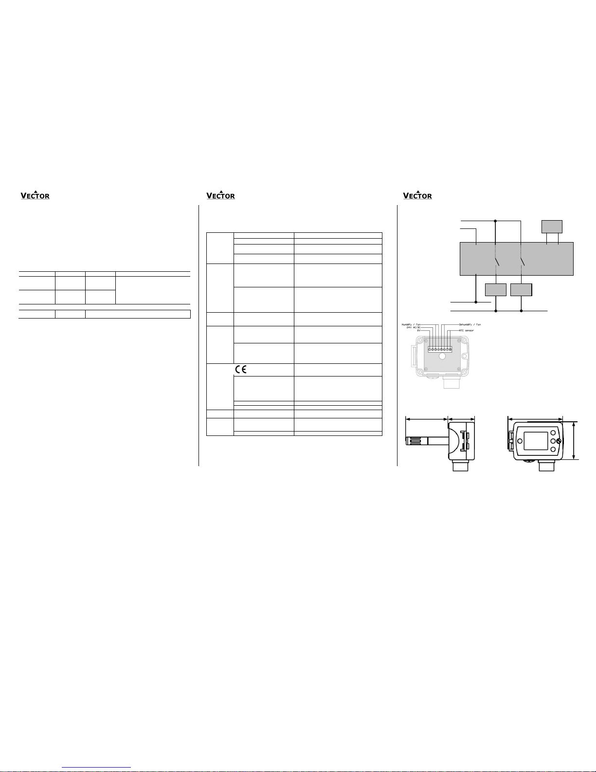
Wiring diagram
Terminal connections
Dimensions mm (in)
0V (GND)
24V AC
2
G
TDC-BH-U
1
G0
0…24V AC
3
Q13
7 8
B1 M
R
T
5
Q23
YB1
4
Q14
YB2
6
Q24
Description:
1. Connection for power-supply (24 V AC/DC, ±10%). In
case of DC, connect the negative power-terminal.
Common connection for analog in- and outputs.
2. Connection for power-supply (24 V AC/DC, ±10%). In
case of DC, connect the positive power-terminal
3. Normally open contact “DO 1” Humidify or Fan
4. Normally open contact “DO 1” Humidify or Fan
5. Normally open contact “DO 2” Dehumidify or Fan
6. Normally open contact “DO 2” Dehumidify or Fan
7. Thermistor input “RT” (Thermistor Sxx-Tn10)
8. Thermistor input “RT” (Thermistor Sxx-Tn10)
2(1.2)A per output!
76 (3.0)
47 (1.9)
91 (3.6)
68 (2.7)
Page 2
Duct humidistat TDC-BH-U-W24
Duct humidistat TDC-BH-U-W24
Duct humidistat TDC-BH-U-W24
Doc: 70-07-0114B-24, V1.4, 20160912 © Vector Controls GmbH, Switzerland Subject to alterations
Configuration parameters
The TDC-BH-U can be adapted to wide variety of applications. The adaptation is done with parameters. The
parameters can be changed on the unit without the need of additional equipment.
Identifying the firmware version
The parameters and functionality of controller depend on its firmware revision. It is therefore important to use
a matching product version and parameter set. The firmware version is marked on the package box of your
product. In order to identify the firmware version of an installed controller, press UP and DOWN keys
simultaneously for three seconds: The display will indicate the firmware version in the upper large digits and
the revision in the lower small digits. Press the LEFT key to return to normal operation.
Setting of user parameters
The TDC-BH-U can be adapted to fit perfectly into your application. The control operation is defined by
parameters. The parameters are set during operation by using the control buttons.
The parameters may only be accessed by entering a code. There are two levels of parameters: User
operation parameters for access control settings, and Expert parameters for control functions and unit setup.
The codes for user levels and expert levels are different. Only control experts should be given the control
parameter code.
The parameters can be changed as follows:
1. Press UP and DOWN button simultaneously for three seconds. The display shows the software
version in the large digits and the product code in the small digits.
2. Pressing the OPTION button will indicate CODE on the small digits and 000 on the large digits.
3. The code for accessing the user parameters is 009
4. Select this using UP or DOWN buttons.
5. Press OPTION button after selecting the correct code.
6. Once logged in, the parameter is displayed immediately.
7. Select the parameters with the UP/DOWN buttons. Change a parameter by pressing the OPTION
button. Three triangles will show up on the lower right and indicate that the parameter may be
modified now. Use UP or DOWN buttons to adjust the value.
8. After you are done, press OPTION or POWER in order to return to the parameter selection level.
Press the POWER button again so as to leave the menu. The unit will return to normal operation if no button
is pressed for more than 5 minutes.
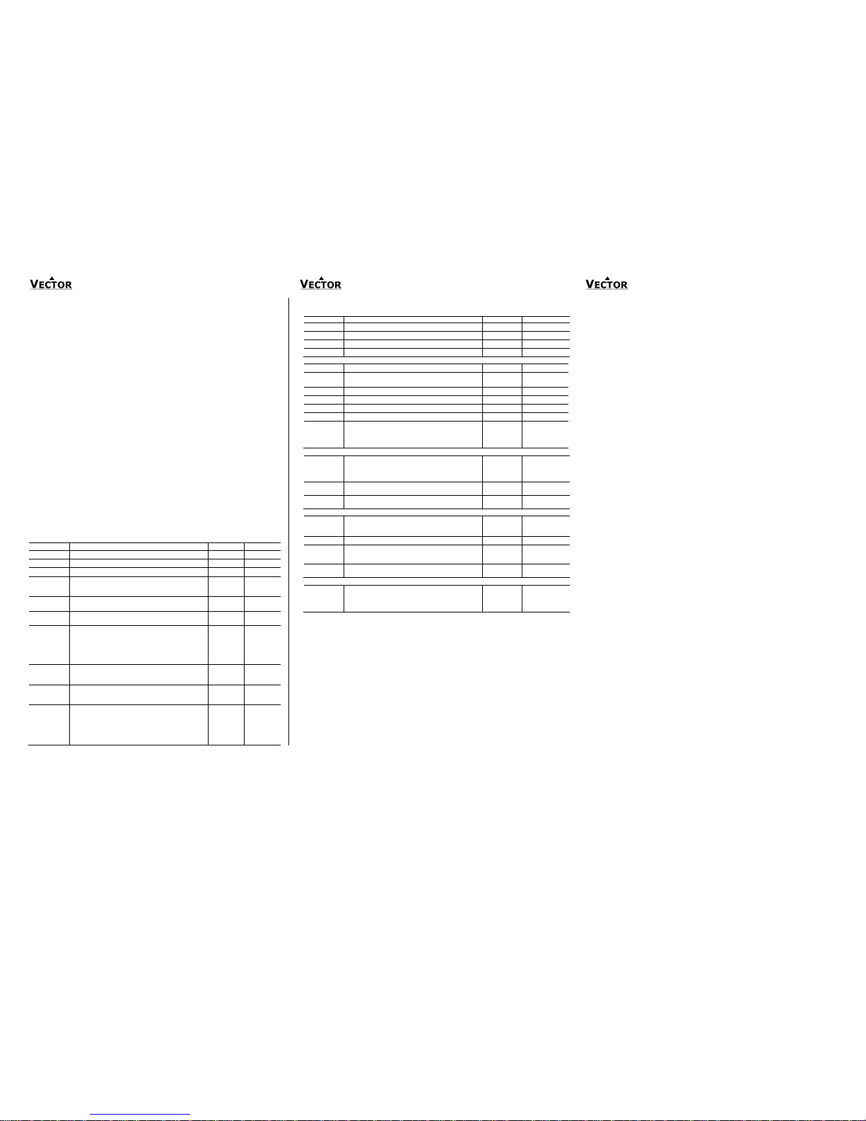
User parameters (password 09)
Parameter
Description
Range
Default
UP 00
Enable change of operation modes
ON, OFF
ON (Enabled)
UP 01
Enable change of set points
ON, OFF
ON (Enabled)
UP 02
Enable access to Time programs
ON, OFF
ON (Enabled)
UP 03
State after power failure:
0 = Switched OFF, 1 = Switched ON, 2 = state before
power failure
0, 1, 2
2
UP 04
Enable Economy functionality
ON, OFF
OFF
(Disabled)
UP 05
Celsius or Fahrenheit, Select ON for Fahrenheit, OFF for
Celsius
ON, OFF
ON (°F)
UP 06
Select contents of small digits in standard mode:
00 = OFF
01 = Set point
02 = Humidity Sensor
03 = External Temperature Sensor
04 = Clock
0…5
04 Deluxe:
show clock
01 Standard:
show set point
UP 07
New: Resolution 0.5% or 1% RH
OFF = Display resolution is 0.5% RH
ON = Display resolution is 1% RH
ON, OFF
OFF
(0.5% RH)
UP 08
Deluxe only
Clock display type:
OFF = Show 24hour clock
ON = Show 12hour clock (AM, PM)
ON, OFF
ON (12h)
UP 09
Deluxe only
Reset timer for override mode: Only available for deluxe
version
0 = Reset of override mode is not active.
1…255 = delay in minutes to return to scheduled operation
if the device is activated while scheduled to be
in OFF or ECO mode.
0…255
60 (Min)
Control parameters (access code: 241)
Warning! Only experts should change these settings! See user parameters for login procedure.
Parameter
Description
Range
Default
CP 00
Minimum set point limit in humidification mode
0…100%
10%
CP 01
Maximum set point limit in humidification mode
0…100%
90%
CP 02
Minimum set point limit in de-humidification mode
0…100%
10%
CP 03
Maximum set point limit in de-humidification mode
0…100%
90%
Controls configuration
CP 04
Economy humidity shift
0…100%
10%
CP 05
Dead zone between humidifying & de-humidifying set point
XDZ
0…100%
10%
CP 06
Delay on humidify – de-humidify change over
0…255 min
5 min
CP 07
Switching Hysteresis
0…100%
3%
CP 08
Delay OFF (Minimum running time) [MM:SS]
00:00 to 98:30
00:10s
CP 09
Delay ON (Minimum stopping time) [MM:SS]
00:00 to 98:30
00:10s
CP 10
Configuration of control mode
0 =W20 = Both Humidification and de-humidification
1 = W24 = Humidification only
2 = W25 = De-humidification only
0 - 2
TDC-BH-W20: 0
TDC-BH-W24: 1
TDC-BH-W25: 2
Output configuration
CP 11
Enable fan (only if CP 10 ≠0)
ON, OFF
TDC-BH-W20:
OFF
TDC-BH-W24: ON
TDC-BH-W25:ON
CP 12
Start delay for fan [MM:SS]
(Time the fan runs before control output starts)
00:00 – 98:30
00:10
CP 13
Stop delay for fan [MM:SS]
(Time the fan keeps running after control output stops)
00:00 – 98:30
01:30
Temperature setback configuration
CP 14
Enable temperature setback
OFF = Temperature setback is disabled
ON = Temperature setback is enabled
ON, OFF
ON
CP 15
Set point limit at full setback
0…100%
20%
CP 16
Lower temperature limit:
Outside temperature with maximum setback
The set point will be equal to the minimum set point limit
-40…60°C
-40…160°F
-30°C (-22°F)
CP 17
Upper temperature limit:
Outside temperature at begin of setback.
-40…60°C
40…160°F
0°C (32°F)
Input signal configuration
CP 18
Number of seconds taken into account to calculate the
averaging input signal.
Low value = fast response
High value = slow response
0…100
10
 Loading...