

Page 1
M - U ( )
Temperature PID Controller
TCY-MT-U Series Intelligent Temperature Controller
Features
• Temperature PID control for HVAC systems.
• Up to 2 modulating outputs for DC 0...10V with 10mV resolution.
• 1 internal temperature sensor and up to 2 external sensor inputs
• Multiple remote control functions on external input
• Password protected programmable user and control parameters
• Blue backlight
Applications
• Various temperature control applications
• Stand alone VAV control for pressure independent actuators
• Water Only Systems: Radiator, floor heating or chilled ceilings
• Individual room control for offices, residential, hotel rooms,
meeting rooms, etc.
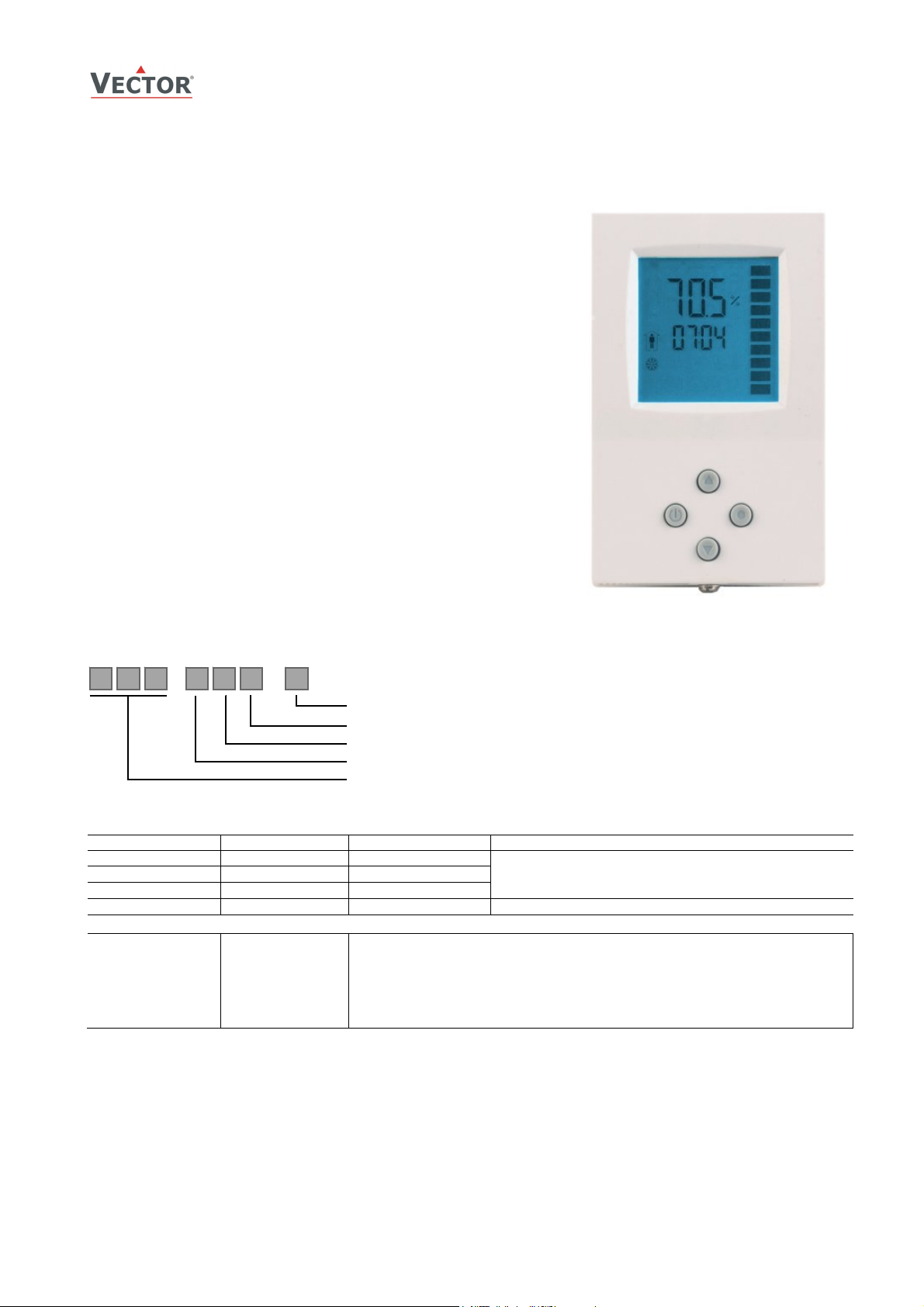
General Description
The TCY-MT-U is a stand-alone electronic universal controller with one
temperature control loop. It may use up to 2 PID sequences. The TCYMT-U features one internal NTC temperature sensor, up to two external
sensor inputs and up to two analog outputs. The configuration has been
reduced to a minimum to allow for a simple and off the shelve usage.
For more advanced features and current in- and outputs the TCI product
range is recommended. The TCY-MT-U can be configured using the
standard operation terminal. No special tool or software is required.
TCY-MT-U
Name
T C Y
-
T
2
Housing: U = Vertical (2x4”) housing, Standard is square housing
Function: 2 = 2 = 2-Pipe, 4 = 4-Pipe
Input: T = Temperature, H = Humidity
Output: M = Modulating, B = Binary
Series: TCY
Ordering
Item Name Item code Control Type Key-data
TCY-MT2-U-W1 40-10 0044-1 Cooling only
TCY-MT2-U-W2 40-10 0044-2 Heating only
TCY-MT2-U 40-10 0044 2-Pipe system
TCY-MT4-U 40-10 0046 4-Pipe system 1 TI, 2 AO
Accessories
S-Tn10-2
SD-Tn10-12-2
SD-Tn10-20-2
SDB-Tn10-12
SDB-Tn10-20
SOA-Tn10
40-20 0001
40-20 0002
40-20 0003
40-20 0051
40-20 0004
40-20 0006
Flying lead sensor with 2 m cable
Flying lead duct sensor 12cm immersion depth, 2m cable
Flying lead duct sensor 20cm immersion depth, 2m cable
Duct sensor with housing, 12cm immersion depth
Duct sensor with housing, 20cm immersion depth
Outdoor sensor
Compact PID controller with:
2 TI, 1 AO
Selection of actuators and sensors
Temperature Sensors:
Use only our approved NTC sensors to achieve maximum accuracy. Recommended is SDB-Tn10-20 as Duct sensor, SRATn10 as Room sensor and SDB-Tn10-20 with AMI-S10 as immersion sensor.
Modulating Actuators:
Choose actuators with an input signal type of 0-10V DC or 2-10V DC.
Doc: 70-00-0176 V1.1, 20100908 © Vector Controls GmbH, Switzerland Page 1
Subject to alteration
Page 2
)
(
)
Technical specifications
Power Supply
Signal inputs
Signal outputs
Environment
Standards
General
Operating Voltage 24 V AC/DC ± 10 %, 50…60 Hz
Power Consumption Max. 1.5 VA
Electrical Connection Terminal Connectors,
Temperature Input
Range 0…50 °C (32…122 °F)
Accuracy 0.5 K
Analog Outputs
Output Signal
Resolution
Maximum Load
Operation
Climatic Conditions
Temperature
Humidity
Transport & Storage
Climatic Conditions
Temperature
Humidity
Mechanical Conditions
Product standards
Automatic electrical controls for
household and similar use
Special requirement on
temperature dependent controls
Degree of Protection IP30 to EN 60529
Safety Class III (IEC 60536)
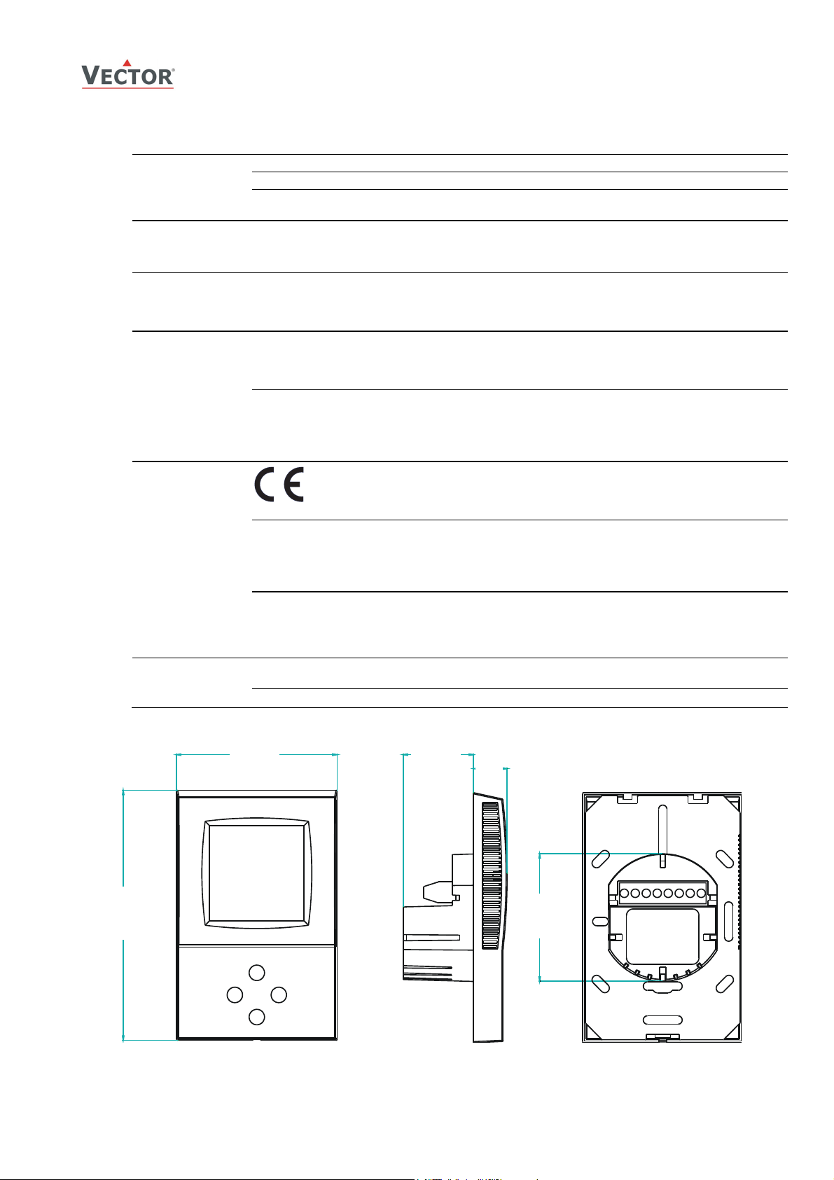
Cover, back part
Mounting Plate
Dimensions (H x W x D) Front part: 112 x 73 x 15 mm (4.4” x 2.9” x 0.6”)
Weight (including package) 270 g (9.5 oz)
conform according to
EMC Standard
89/336/EEC
EMEI Standard 73/23/EEC
TCY-MT-U
Temperature PID Controller
wire 0.34…2.5 mm
AO1, For TCY-MT4-U AO2
DC 0...10 V
9.76 mV (10 bit)
2 mA
To IEC 721-3-3
class 3 K5
0…50 °C (32…122 °F)
<95 % r.H. non-condensing
To IEC 721-3-2 and IEC 721-3-1
class 3 K3 and class 1 K3
-25…70 °C (-13…158 °F)
<95 % r.H. non-condensing
class 2MT2
EN 61 000-6-1/ EN 61 000-6-3
EN 60 730 –1
EN 60 730 – 2 – 9
Fire proof ABS plastic (UL94 class V-0)
Galvanized Steel
Power case: ø 58 x 32 mm (ø 2.3” x 1.3”)
2
(AWG 24…12)
Dimensions [mm] (inch)
73 (2.9)
112 (4.4)
Doc: 70-00-0176 V1.1, 20100908 © Vector Controls GmbH, Switzerland Page 2
Subject to alteration
32 (1.2
15
0.6
58 (2.3)
Page 3
G0
U
G0
U2
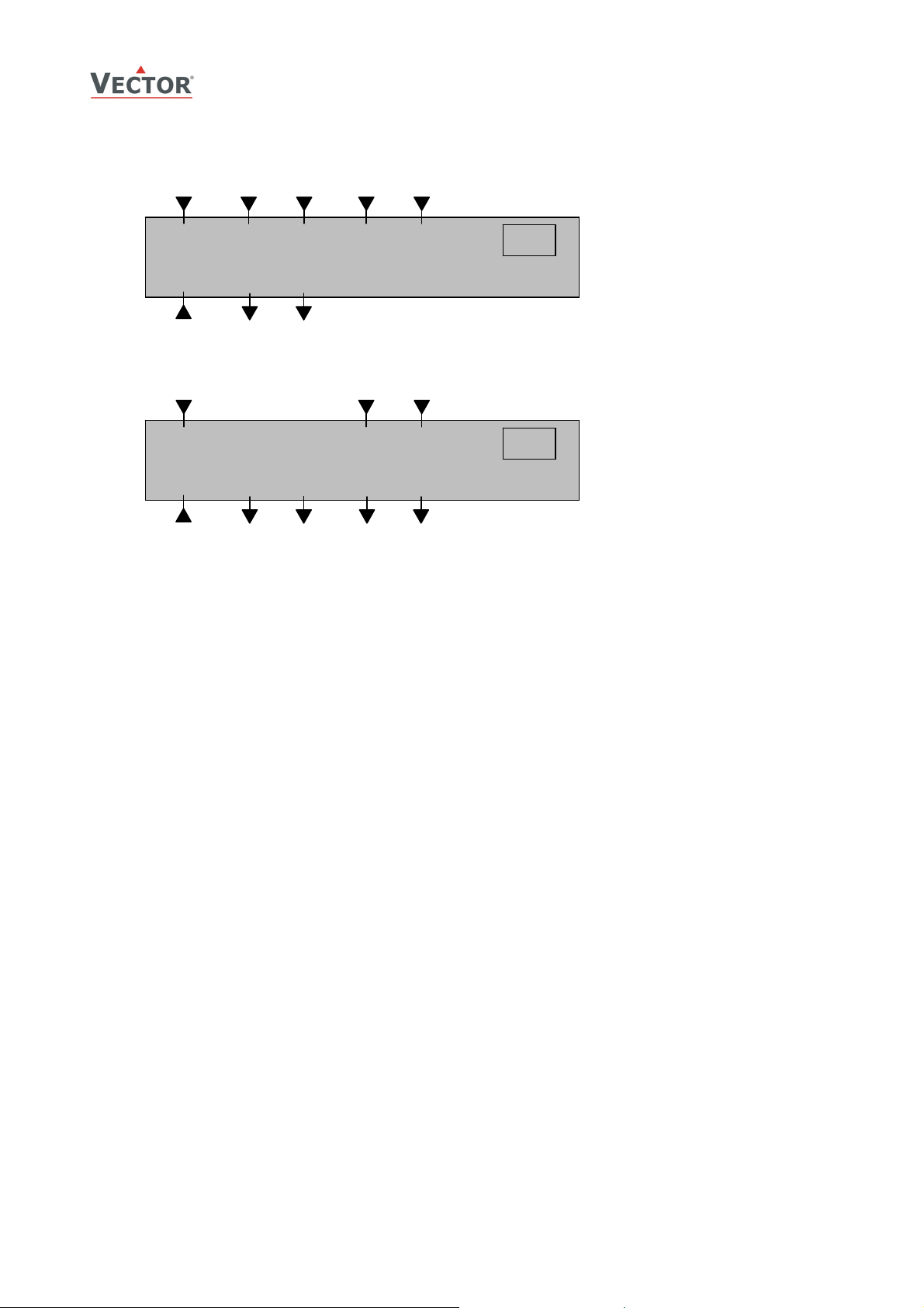
Connection diagram
24V AC/DC
COM
TCY-MT-U
Temperature PID Controller
X
T CO
IN
COM
X
T EXT
IN
0V (COM)
24V AC/DC
0V (COM)
Description:
G0 Power supply: 0V, -24VDC, internally connected to signal common
G Power supply: 24VAC, +24VDC
M Signal common: Common 0 potential for analog inputs and analog outputs.
X1 External temperature input: NTC 10kΩ @ 25°C (77°F)
TCY-MT2-U:
X2 Changeover input: NTC 10kΩ @ 25°C (77°F)
U1 Analog output: 0…10 V DC
TCY-MT4-U:
U1 Analog heating output: 0…10 V DC
U2 Analog cooling output: 0…10 V DC
2
G
1
G0
2
G
1
G0
5
M
3
G0
COM
3
Signal
COM
6
X2
4
U1
H/C
OUT
4
1
Heat
OUT
7
M
Signal
COM
7
M
5
Signal
COM
8
X1
X
T EXT
IN
8
X1
6
Cool
OUT
X
T INT
TCY-MT2-U
X
T INT
TCY-MT4-U
Mechanical Design and installation
The unit consists of two parts: (a) The power case with attached mounting plate and (b) the front part.
Mounting location
• On an easy accessible interior wall, approx. 1.5 m (4.5’) above the floor in an area of average temperature.
• Avoid exposure to direct sunlight or other heat sources, e.g. the area above radiators and heat emitting electrical
equipment.
• Avoid locations behind doors, outside walls and below or above air discharge grills and diffusers.
• Location of mounting is less critical if external temperature sensors are used
Installation
1. Connect the wires to be connected to the terminals of the power case according to wiring diagram
2. Install the mounting plate to the flush mounting box. Make sure that the nipple with the front holding screw is
facing to the ground. Make sure the mounting screw heads do not stand out more than 5 mm (0.2”) off the
surface of the mounting plate.
3. Ensure that the jumpers are set correctly.
4. Slide the two latches located on the top of the front part into the hooks at the upper side of the mounting plate.
5. Carefully lower the front part until the interconnector reaches the mounting-plate. Continue pressing in a gentle
way until the front part is fully connected. While inserting the connectors, a slight resistance can be felt. This is
normal. Do not use excessive force!
6. With a Philips-type screw driver of size #2, carefully tighten the front holding screw to secure the front part to
the mounting plate. This screw is located on the front lower side of the unit. There is no need to tighten the
screw too much.
Doc: 70-00-0176 V1.1, 20100908 © Vector Controls GmbH, Switzerland Page 3
Subject to alteration
Page 4

8
Temperature PID Controller
Display and Operation
The operation terminal uses an LCD display and four operation buttons.
1
5
6
7
Legend:
1. 4-digit display of current value, time, control parameter or set point
2. Unit of displayed value, °C, °F, % or none
3. Graphical display of output or input value with a resolution of 10%
4. 4-digit display of current value, time, control parameter or set point
5. Operation modes: Comfort mode, Standby mode, Energy Hold Off
6. Symbols: Heating active: , Cooling Active: external temperature sensor connected:
7. POWER button: Standard function: Pressing the button less than 2 sec toggles standby and comfort mode.
Pressing the button for more than 2 seconds switches the unit off.
Programming function: ESC function, to return to previous level or ignore changed value
8. UP buttons: increment set points and parameters, select menu options
9. OPTION button: Standard function: If pressed less than 2 sec access for different control modes
If pressed for more than 2 sec starts operation level for advanced users. Change of time schedules, offsets and
heat – cool settings.
Programming function: Acts as Enter to select menu option or accept changed parameter value.
10. DOWN buttons: decrement set points and parameters, select menu options
2
3
4
9
T
TCY-MT-U
Operation Modes
• Comfort: The unit is in full operation mode. All the control functions are operating according to their setpoints.
The unit displays occupied mode.
• Standby: The set points are shifted according to parameters CP04. The heating parameter is shifted down and
cooling parameter up. The unit displays unoccupied mode. Outputs are limited to CP17 standby maximum. For
two stages heating or cooling the second stage will not operate while in standby mode. Standby operation may
be disabled with UP06.
• Energy Hold-Off (EHO): The unit is switched off. All outputs are off. The temperature will still be monitored in
order to activate the unit in case of frost. (If frost protection is enabled). Off is displayed.
Activation of operation modes
• Via operation terminal
• Via external input
Doc: 70-00-0176 V1.1, 20100908 © Vector Controls GmbH, Switzerland Page 4
Subject to alteration
Page 5

TCY-MT-U
Temperature PID Controller
Operation of the Terminal Unit
Switching ON
The unit is switched on by pressing the POWER button. It will start up in comfort mode.
Changing between COMFORT and STANDBY
Pressing the POWER button for less than 2 seconds toggles between STANDBY and COMFORT modes. Standby mode may
be disabled with UP06.
Switching OFF
Pressing the POWER button for more than 2 seconds, will switch the unit off. OFF and current time will be displayed in the
LCD for the deluxe unit. Current temperature and OFF is displayed for the basic unit.
Changing of set points
Change the set point with the UP/DOWN buttons. Changing of set points may be disabled with UP01.
Manually activating heating or cooling mode
Pressing the option button for more than three seconds will toggle Heating – Cooling mode.
Manual Heat/Cool change may be disabled with UP03
Power Failure
All the parameters and set points are memorized and do not need to be reentered. Depending on UP05 the unit will
remain switched off, switch on automatically or return to the operation mode it was in before the power failure.
Deluxe version only: Timer operation and daytime setting will be retained for 24h. The controller has to be connected to a
power supply for at least 10 hours for the backup function to operate accordingly.
Error messages
The TCY-MT-U may display the following error condition:
Err1: The connection to the temperature sensor may be interrupted or the temperature sensor is damaged.
The output is switched off. Verify parameter settings and wiring.
Doc: 70-00-0176 V1.1, 20100908 © Vector Controls GmbH, Switzerland Page 5
Subject to alteration
Page 6

TCY-MT-U
Temperature PID Controller
Setting of parameters
The TCY-MT-U is an intelligent controller and can be adapted to fit perfectly into your application. The control operation is
defined by parameters. The parameters are set during operation by using the standard operation terminal.
The parameters are password protected. There are two levels of parameters: User operation parameters for access control
settings and Expert parameters for control functions and unit setup. The passwords for user levels and expert levels are
different. Only control experts should be given the control parameter password.
The parameters can be changed as follows:
1. Press UP and DOWN button simultaneously for three seconds. The display will indicate the firmware version in the
upper large digits and the revision in the lower small digits. Pressing any key will show: CODE.
2. Select a password using UP or DOWN buttons. Dial 009 in order to get access to the user parameters.
Press OPTION after selecting the correct password.
3. Once logged in, the parameter is displayed immediately
4. Select the parameters with the UP/DOWN keys. Change a parameter by pressing the OPTION key. The MIN and
MAX symbols show up and indicate that the parameter may be modified now. Use UP and DOWN key to adjust
the value.
5. After you are done, press OPTION or POWER in order to return to the parameter selection level.
6. Press the POWER key again so as to leave the menu. The unit will return to normal operation if no key is pressed
for more than 5 minutes.
User Parameters (Password 009)
Parameter Description Range Default
UP 00 Enable access to operation modes ON, OFF ON
UP 01 Enable access to set points ON, OFF ON
UP 02 Not used ON, OFF OFF
UP 03 Enable manual change of heating / cooling mode
Has no influence for TCY-MT2-U-W1 and TCY-MT2-U-W2
UP 04 Not used ON, OFF OFF
UP 05 State after power failure:
0 = off, 1 = on, 2 = state before power failure
UP 06 Enable standby functionality ON, OFF ON
UP 07 Celsius or Fahrenheit, ON for Fahrenheit, OFF for Celsius ON, OFF OFF (Celsius)
UP 08 Calibration value of temperature sensor. This value is
calibrated at manufacturing of the thermostat. If required it is
possible to shift the temperature –10° to +10° in 0.1° steps.
UP 09 Enable Frost Protection ON, OFF TCY-MT2-U-W1: OFF
ON, OFF ON
0, 1, 2 2
-10…10 0
TCY-MT2-U-W2: ON
TCY-MT2-U: ON
TCY-MT4-U: ON
Doc: 70-00-0176 V1.1, 20100908 © Vector Controls GmbH, Switzerland Page 6
Subject to alteration
Page 7
TCY-MT-U
T
Temperature PID Controller
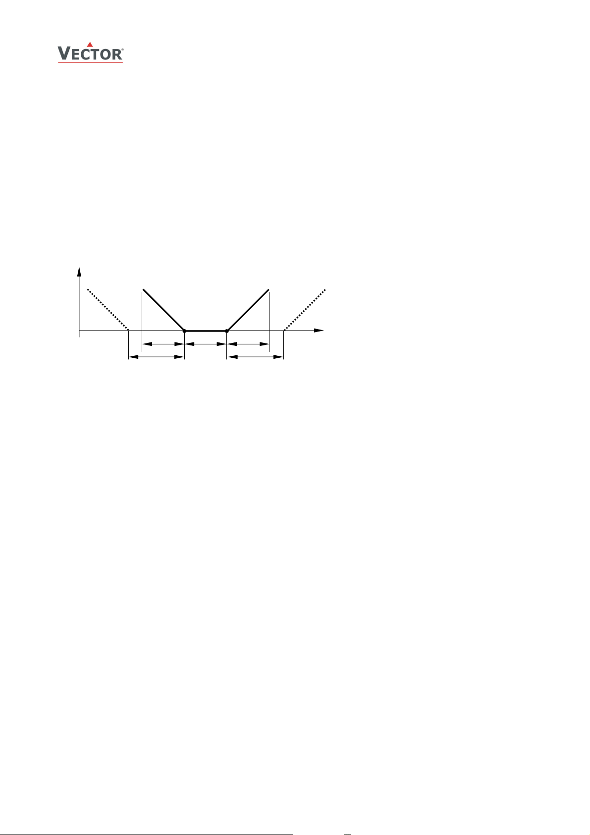
Control Functions
Temperature control loop: Signal input: either internal or external passive temperature probe
Manipulation of the set point
Standby set point shift X
point W
is reduced and the cooling set point WC increased by the value of the standby set point shift X
H
Dead Zone Span X
: For TCY-MT4-U only. The dead zone span lies between the heating and the cooling set point.
DZ
Minimum and Maximum Set Point Limits: Limits the adjustable range of the loop set point. The limits for heating and
cooling sequence may be chosen individually.
PID-Control
Each loop has one reverse (heating) and one direct (cooling) acting PID sequence.
Heating, Reverse
YH1, Y
100
0
: This function shifts the set point while the operation mode is standby. The heating set
SBY
R1
Cooling, Direct
Y
C1, YD1
W
W
XPH
X
SBY
H
XDZ
C
X
PC
X
SBY
[°C, F]
U [V, mA]
Legend:
T, U Input Signal
X
P-band Heating, Direct
PH
X
P-band Cooling, Reverse
PC
X
Dead zone
DZ
X
Standby set point shift
SBY
W
Set point Heating, Reverse
H
W
Set point Cooling, Direct
C
Y
P sequence Heating, Reverse
H1, YR1
Y
P sequence Cooling, Direct
C1, YD1
SBY
.
Proportional Control:
Proportional-band XP: The proportional part is defined through the p-band. A narrow P-band increases the sensitivity of
the controller. Typical values used are 1 – 1.5K for heating, 2 – 3K for cooling sequences.
The P-band should be extended in case the ID-Part is active, to prevent instability.
Integral & Differential Control:
The algorithm used reduces the swinging tendency of the control loop and improves a direct approach of the current value
to the setpoint. The ID part is defined by two parameters:
The time interval TI specifies how fast the control sequence reacts. A low value (short interval) increases the swinging
tendency and with it the risk of an instable loop. A high value (long interval) slows than reaction time.
The integral gain factor KI specifies how strong the control sequence reacts. Opposite to TI a high gain factor increases
instability and a low factor delays the response of the controller.
The setting of these two parameters depend on the type and size of heating or cooling equipment used, the size of the
room and the usage of the room. Here are some values that may be considered. These must be verified upon
commissioning.
We recommend the following values:
For air based heating systems: KI = 0.5
For floor heating systems: KI = 0.3
For air cooling systems: KI = 1.0
Doc: 70-00-0176 V1.1, 20100908 © Vector Controls GmbH, Switzerland Page 7
Subject to alteration
Page 8

TCY-MT-U
A
p
Temperature PID Controller
Temperature Input
The TCY-MT-U includes an NTC-based passive temperature sensor. A
sensor of the same type can be connected as alternative control input or
remote control input. The TCY-MT2-U may use an additional input as
changeover input. The accuracy of the temperature input is shown in the
table to the right. Specified accuracy can only be guaranteed by using an
approved temperature sensor. For best results use Sxx-Tn10 sensors.
Options for input X1
These functions are activated by parameters
External controls input The control input is provided by the external input. The internal input will not be
used.
Remote Enable Opening the external temperature input will force the unit into the OFF operation
mode. The operation mode cannot be overridden by using the terminal. Connecting
the binary input to GND returns control of the operation mode to the terminal. This
function may be used as window contact to prevent loss of energy.
Toggle of Standby and
Comfort operation modes
Standby and Comfort modes are controlled through an external contact by connecting
the external temperature input to ground
Activation Delay: Defines the delay the binary contact has to be open before
standby mode is activated.
This function may be used together with key card switches for hotels or motion
detectors for offices.
ccuracy in Kelvin,
Tem
1.0
0.5
0.2
0 50 100
erature Input
T °C
Auto change over instructions for input X2 (TCY-MT2 only):
There are several ways to switch a 2-pipe system from heating to cooling. The temperature of the supply media or the
outside temperature may be measured. The controller detects the mode automatically. If heating limit is above cooling
limit, supply media mode is selected. If heating limit is below cooling limit, outdoor mode applies.
Heating and cooling may be as well changed by an open contact switched to GND. Note: all ground levels of involved
controllers must be the same in case more than one controller is switched.
Supply media Set auto change over limit heating above the change over limit cooling but below the
Outside temperature Set auto change over limit heating at the temperature where heating should start. For
Open Contact: heating active
while contact is closed
Open Contact: cooling active
while contact is closed
temperature of the heating media. For example 25°C (77F).
Set auto change over limit cooling above the temperature of the cooling media. For
example 18°C (64F).
example if outside temperature is below 15°C (59F).
Set auto change over limit cooling at the temperature where cooling should start. For
example at 25°C (77F).
Auto change over limit heating = 25°C (77F)
Auto change over limit cooling = 15°C (59F)
Auto change over limit heating = 15°C (59F)
Auto change over limit cooling = 25°C (77F)
Doc: 70-00-0176 V1.1, 20100908 © Vector Controls GmbH, Switzerland Page 8
Subject to alteration
Page 9

TCY-MT-U
T
Temperature PID Controller
Output Configuration
Analog Output
The analog output is fixed to 0-10VDC. The signal range may be configured with parameters. It is thus possible to directly
set min and maximum flow levels for VAV systems for example.
To adjust the output for a 2-10VDC signal set the minimum to 20% and keep the maximum at 100%
Output in standby mode
The analog output in standby mode may be reduced in order to save energy. The default value is set to 50%.
VAV applications
The following description is for 4-pipe systems. The settings apply to TCY-MT4-U.
In the VAV control sequence, at peak cooling the airflow setpoint is the maximum amount of air the VAV box is set to
deliver. It may be adjusted through the maximum limit on the analog output in cooling mode (CP16). As cooling
requirements decrease, airflow dwindles until it reaches its minimum setpoint. This setpoint will be based on the airflow
needed at design cooling and is typically 10% to 15% of maximum cooling airflow. Minimum airflow can be adjusted by
the minimum limit on the analog output in cooling mode (CP15) and in heating mode (CP13). When it reaches this
minimum, the system is in its dead band and is neither heating nor cooling. As the system moves into heating mode, the
airflow rate increases until it reaches the maximum airflow required for heating mode. This is typically 30 to 50% of
maximum airflow of cooling mode. The parameter for this is the maximum limitation in heating mode (CP14).
100
50
0
Heating
YH1, Y
heating max: CP14
Min heating: CP13
R1
W
W
H
C
XDZ
Cooling
Y
C1, YD1
Min cooling: CP15
Max cooling: CP16
[°C, F]
U [V, mA]
Configuration parameters for firmware version 1.1
The TCY-MT-U is preset to work for most applications. For special requirements it can be fine tuned to work ideal with a
simple parameter setup routine. The parameters can be changed on the unit without the need of additional equipment.
Identifying the firmware version
The parameters and functionality of controller depend on its firmware version and revision. It is therefore important to use
a matching product version and parameter set. The Firmware version and revision version can be found when pressing
simultaneously the S and T keys during several seconds. On the upper 7 segment display, the firmware version can be
found, on the lower 7 segment display the current revision index (or “sub-version”).
Doc: 70-00-0176 V1.1, 20100908 © Vector Controls GmbH, Switzerland Page 9
Subject to alteration
Page 10

TCY-MT-U
Temperature PID Controller
Control Parameters (Access Code: 241)
Warning! Only experts should change these settings! See user parameters for login procedure.
Parameter Description Range Default
CP 00 Minimum setpoint limit in Heating mode 0…60°C (32..160°F) 16°C (61°F)
CP 01 Maximum setpoint limit in Heating mode 0…60°C (32..160°F) 30°C (86°F)
CP 02 Minimum setpoint limit in Cooling mode 0…60°C (32..160°F) 18°C (65°F)
CP 03 Maximum setpoint limit in Cooling mode 0…60°C (32..160°F) 30°C (86°F)
Controls configuration
Parameter Description Range Default
CP 04 Economy temperature shift 0…100°C (200°F) 5.0°C (10°F)
CP 05 TCY-MT4 only:
Dead zone between heating & cooling set point X
DZ
CP 06 TCY-MT4 only: Delay on Heat/Cool change over 0…255 min 5 min
CP 07 P – band heating XPH 0…100°C (200°F) 2.0°C (4.0°F)
CP 08 P – band cooling XPC 0…100°C (200°F) 2.0°C (4.0°F)
CP 09 KIH, Integral gain heating, in 0.1 steps, (TI is fixed to 4s)
0 disables ID part
low value = slow reaction
high value = fast reaction
CP 10 KIC, Integral gain cooling, in 0.1 steps, 0 disables I part 0…25.5 0.0
CP 11 Configuration of operation mode
0 = TCY-MT2-W1 = Cooling mode Y
1 = TCY-MT2-W2 = Heating mode: Y
C1
H1
2 = TCY-MT2 = Heating and Cooling (2 pipe system), YH1 + Y
3 = TCY-MT4 = Heating and Cooling (4 pipe system), YH1 + Y
Analog Output
Parameter Description Range Default
CP 12 Manual override of analog outputs
OFF = Control mode
ON = Manual mode (0 – 100%)
CP 13 Min output for AO1 (For TCY-MT4-U = Heating output) 0 – 100 % 0%
CP 14 Max output for AO1 (For TCY-MT4-U = Heating output) 0 – 100 % 100%
CP 15 Min output for AO2 (For TCY-MT4-U = Cooling output) 0 – 100 % 0%
CP 16 Max output for AO2 (For TCY-MT4-U = Cooling output) 0 – 100 % 100%
CP 17 Maximum limitation in standby mode 0 – 100 % 50%
Input configuration
Parameter Description Range Default
CP 18 Configuration of remote control input (X1)
0 = Control input if temperature sensor connected
1 = Occupation sensor – Comfort / Standby
2 = Remote enable – Comfort / OFF
3 = Keycard function: fixed setpoint
CP 19 Activation delay (Minutes) = the time the binary input needs
to be open before standby/off mode is activated.
CP 20 Fixed setpoint for key card function in heating mode 0…60°C (32..160°F) 17°C (63°F)
CP 21 Fixed setpoint for key card function in cooling mode 0…60°C (32..160°F) 27°C (81°F)
CP 22 For TCY-MT2-U only: Enable Auto changeover ON, OFF OFF
CP 23 For TCY-MT2-U only: Auto-changeover limit heating 0…60°C (32..160°F) 30°C (86°F)
CP 24 For TCY-MT2-U only: Auto changeover limit cooling 0…60°C (32..160°F) 15°C (59°F)
0…100°C (200°F) 1.0°C (2°F)
0…25.5 0.0
TCY-MT2: 0 - 2
TCY-MT4: 0 – 3
TCY-MT2-W1: 0
TCY-MT2-W2: 1
TCY-MT2: 2
C1
C1
TCY-MT4: 3
ON, OFF OFF
0…3 0
0…255 min 5
Doc: 70-00-0176 V1.1, 20100908 © Vector Controls GmbH, Switzerland Page 10
Subject to alteration
 Loading...