

Vector TCY3-T0121R, TCY3-T0121R-D, TCY3-T0121R-U-D, TCY3-T0121R-H, TCY3-T0121R-H-U User Manual
...Page 1
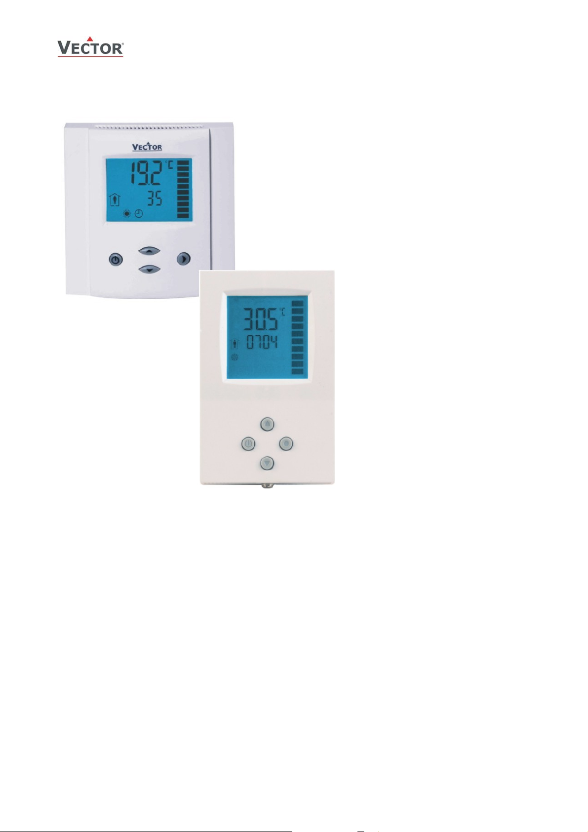
TCY3-T0121R Series Intelligent Compact Controller
Features
• Temperature control for 2-pipe, 4-pipe HVAC
systems.
• -H version: Humidity control with integrated
humidity sensor
• Universal PID and binary control for any
analog input/output signal and range
• 4 independent PID sequences, 12
independent binary sequences
• 1 modulating output for DC 0...10V or 0…20
mA actuators with 10 bit resolution.
• 1 Input for DC 0…5V, 0…10V or 0…20 mA
sensors with 10 bit resolution
• 1 internal temperature sensor and 1 external
sensor input
• Multiple functions on external input: auto
changeover, remote control
• Monitoring of low and high limits on all inputs.
Programmable reaction in case of alarm.
• Feedback function for internal sensors and
set points.
• Special functions for dehumidifying, set point
shift and VAV control
• Transformation of display value according to
analog sensor range
• Password protected programmable user and
control parameters
• Blue backlight
• Deluxe Version only:
o Power Cap protected real time clock with 24h
power backup
o 16 switching times, grouped in 4 time
schedules.
o Infrared remote control
TCY3-T0121R
Applications
• Air Only Systems: Constant or Variable Air Volume systems for single or dual duct systems with options of:
• Air/Water Systems:
• Water Only Systems: Radiator, floor heating or chilled ceilings
• Individual room control for hotel rooms, meeting rooms, etc.
o up to two reheat stages
o supply air, extract air cascade control
o humidity control
o Control for variable speed fans
o Fan Coil units for 2-pipe or 4-pipe systems with options of:
Humidity control
Pressure control
o radiator control, chilled ceiling
General Description
The TCY3 is a stand-alone electronic universal controller with two autonomous control loops. Each control loop may use up
to 2 PID sequences and 6 binary sequences. The TCY3-T0121R features 1 NTC temperature sensor and 1 analog input, 2
binary outputs and one analog output. The outputs need to be assigned to the control sequences by parameters. A
detailed configuration is possible by following a simple setup routine. The TCY3 can be configured using the standard
operation terminal. No special tool or software is required.
Doc: 70-000002 V1.0, 20101115 © Vector Controls GmbH, Switzerland Page 1
Subject to alteration
Page 2
)
(
)
(
)
Name
TCY3-T0121R Technical Data
C YT T 0 1 2 1 H(- ) U(- ) D(- )-3
Ordering
Model Stock code Variant Mounting size Type Key-data
TCY3-T0121R 40-10 0021 Standard
TCY3-T0121R-D 40-10 0022 Deluxe
TCY3-T0121R-U 40-10 0023 Standard
TCY3-T0121R-U-D 40-10 0024 Deluxe
TCY3-T0121R-H 40-10 0025 Standard
TCY3-T0121R-H-D 40-10 0026 Deluxe
TCY3-T0121R-H-U 40-10 0027 Standard
TCY3-T0121R-H-U-D 40-10 0028 Deluxe
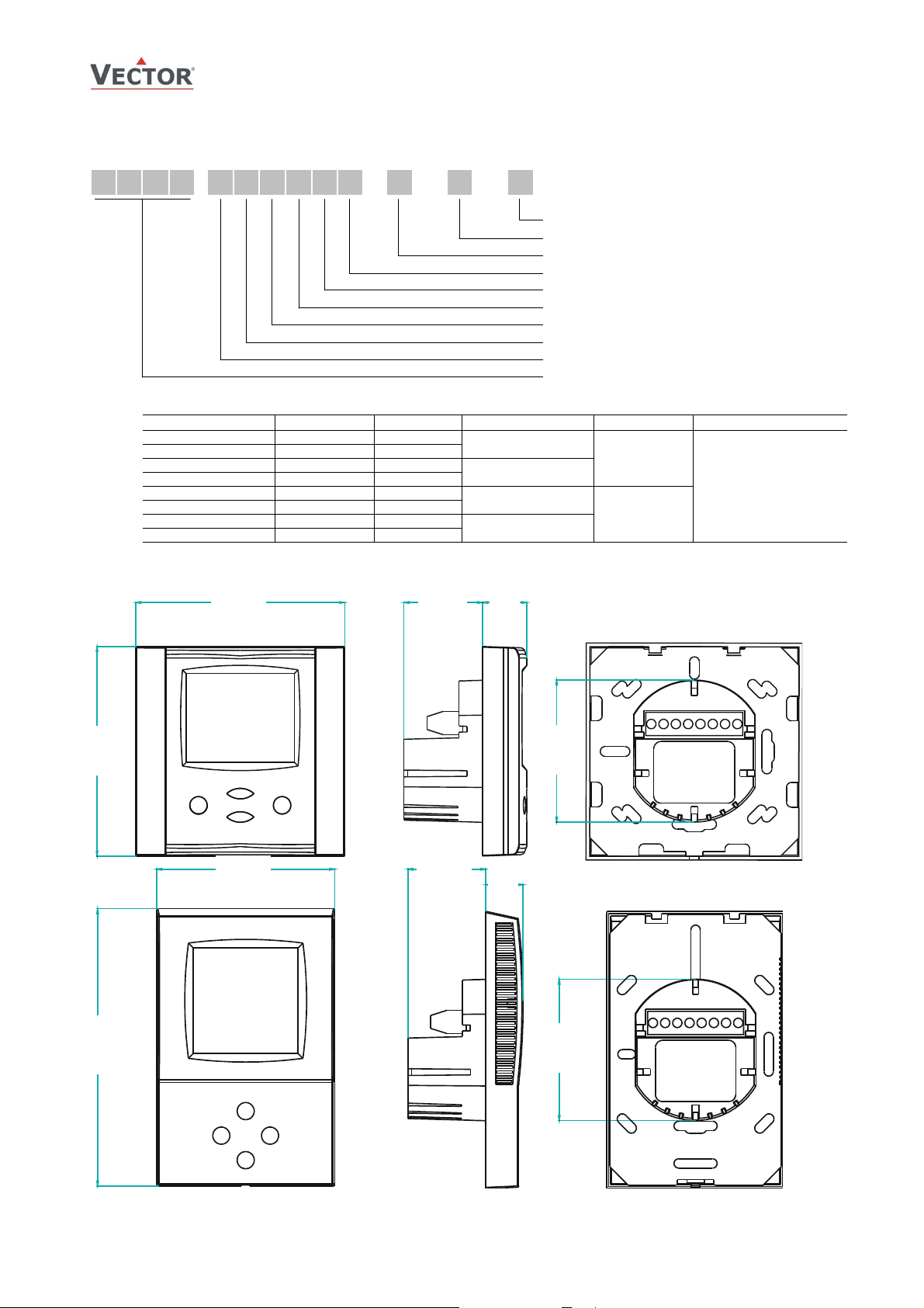
Dimensions [mm] (inch)
88 (3.5) 32 (1.2
R
88mm x 88mm
2” x 4”
88mm x 88mm
2” x 4”
21
(0.8)
Deluxe version
2” x 4” housing
Integrated Humidity sensor
Relays for binary outputs
Number of analog outputs (AO) = 1
Number of binary output (DO) = 2
Number of analog inputs (AI) = 1
Number of binary inputs (DI) = 0
With external temperature input (RT)
Series (TCY3)
No humidity
sensor
With humidity
sensor
Compact PI controller
with:
1 TI int or ext
1 AI
2 DO (Relay)
1 AO
88 (3.5)
73 (2.9)
112 (4.4)
32
1.2
15
0.6
58 (2.3)
58 (2.3)
Doc: 70-000002 V1.0, 20101115 © Vector Controls GmbH, Switzerland Page 2
Subject to alteration
Page 3

Technical specifications
Power Supply
Signal inputs
Signal outputs
Environment
Standards
General
Operating Voltage 24 V AC/DC ± 10 %, 50…60 Hz
Power Consumption Max. 3 VA
Electrical Connection Terminal Connectors,
Internal rectification:
Signal ground = power ground
Clock backup 24 hours (Deluxe version only)
Analog Input
Input Signal
Resolution
Temperature Input
Range Int. NTC: 0…50 °C (32…122 °F)
Accuracy -40…0 °C (-40…32 °F): 0.5 K
Humidity Input: (-H Version only)
Range
Accuracy at 55 % r.H.
Hysteresis
Repeatability
Stability
Analog Outputs
Output Signal
Resolution
Maximum Load in voltage mode
Relays Outputs
AC Voltage
DC Voltage
Operation
Climatic Conditions
Temperature
Humidity
Transport & Storage
Climatic Conditions
Temperature
Humidity
Mechanical Conditions
Product standards
Automatic electrical controls for
household and similar use
Special requirement on
temperature dependent controls
Degree of Protection IP30 to EN 60 529
Safety Class III (IEC 60536)
Cover, back part
Mounting Plate
Dimensions (H x W x D) Front part: 88 x 88 x 21 mm (3.5” x 3.5” x 0.8”)
Dimensions (H x W x D), U-version Front part: 112 x 73 x 15 mm (4.4” x 2.9” x 0.6”)
Weight (controller only) 180 g (6.3 oz)
Weight (including package) 260 g (9.2 oz)
conform according to
EMC Standard
89/336/EEC
EMEI Standard 73/23/EEC
TCY3-T0121R Technical Data
wire 0.34…2.5 mm
Half wave rectified
Security transformer required
AI1
0...10 V or 0...20 mA
9.76 mV or 0.019 mA (10 bit)
Ext. NTC (Sxx-Tn10 sensor): -40…140 °C (-40…284 °F)
0…50 °C (32…122 °F): 0.2 K
50…100 °C (122…212 °F): 0.5 K
> 100 °C (> 212 °F): 1 K
H1 Thermoset Polymer-Based Capacity
0…100 % r.H.
± 3.0 % at 25 °C (77 °F)
± 3 % between 15…90 % r.H.
± 0.5 %
± 0.5 % / year if used within 0…50 °C (32…122 °F)
AO1
DC 0...10 V or 0...20 mA (250 Ω max.)
9.76 mV resp. 0.019 mA (10 bit)
10 mA
DO1, DO2
0…48 VAC, 2 (1.2) A max. each output
0…30 VDC, 2 (1.2) A max. each output
To IEC 721-3-3
class 3 K5
0…50 °C (32…122 °F)
<95 % r.H. non-condensing
To IEC 721-3-2 and IEC 721-3-1
class 3 K3 and class 1 K3
-25…70 °C (-13…158 °F)
<95 % r.H. non-condensing
class 2M2
EN 61 000-6-1/ EN 61 000-6-3
EN 60 730 –1
EN 60 730 – 2 – 9
Fire proof ABS plastic (UL94 class V-0)
Galvanized Steel
Power case: ø 58 x 32 mm (ø 2.3” x 1.3”)
Power case: ø 58 x 32 mm (ø 2.3” x 1.3”)
2
(AWG 24…12)
Doc: 70-000002 V1.0, 20101115 © Vector Controls GmbH, Switzerland Page 3
Subject to alteration
Page 4
TCY3-T0121R Technical Data
Selection of actuators and sensors
Temperature Sensors:
Use only our approved NTC sensors to achieve maximum accuracy. Recommended is SDB-Tn10-20 as Duct sensor, SRATn10 as Room sensor and SDB-Tn10-20 with AMI-S10 as immersion sensor.
Modulating Actuators:
Choose actuators with an input signal type of 0-10 V DC or 4-20 mA. Minimum and maximum signal limitations may be
set in software.
Floating Actuators:
Actuators with constant running time are recommended. Observe power limits on binary devices.
Binary auxiliary devices:
E.g. pumps, fans, on/off valves, humidifiers, etc. Do not directly connect devices that exceed 48 VAC, 2(1.2) A. Observe
startup current on inductive loads.
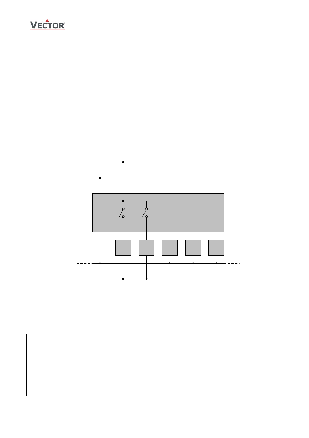
Connection diagram
0...48 V
0...30 V
AC
DC
24V AC/DC ±10%
0V (GND)
Description:
Binary output 1: 0…48 VAC or 0…30 VDC
Y
B1
Y
Binary output 2: 0…48 VAC or 0…30 VDC
B2
X
Analog input 1: 0…5 V, 0…10 V or* 0…20 mA
A1
Y
Analog output 1: 0…10 V or* 0…20 mA
M1
R
Temperature input 1: NTC 10kΩ @ 25°C (77°F)
T
23
145678
0V
*
) selectable by jumper
TCY3-T0121..
Y
B1
Y
B2
Y
M1
X
A1
R
T
!
U
WARNING:
Power supply is half-wave rectified:
Signal ground = Power ground
Connect through a safety isolation transformer
Doc: 70-000002 V1.0, 20101115 © Vector Controls GmbH, Switzerland Page 4
Subject to alteration
Page 5
TCY3-T0121R Installation
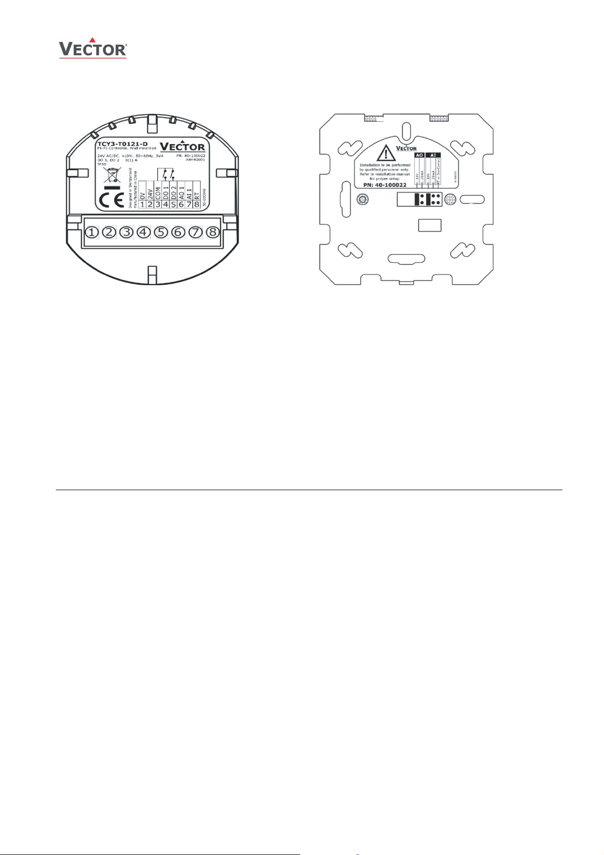
Connection terminals and jumpers
Terminal-description:
1. Connection for power-supply (24 V AC/DC, ±10%).
In case of DC, connect the negative powerterminal. Common connection for analog in- and
outputs.
2. Connection for power-supply (24 V AC/DC, ±10%).
In case of DC, connect the positive power-terminal
3. Common for relays
4. Switched contact “DO 1” (Max. 2 (1.2A)
5. Switched contact “DO 2” (Max. 2 (1.2A)
6. Analog-output “AO 1” (Jumper-selectable between
0…10 V or 0…20 mA)
7. Analog input “AI 1” (Jumper-selectable between
0…10 V or 0…20 mA)
8. Thermistor input “RT” (Thermistor Sxx-Tn10)
Jumper-settings (standard version shown):
Jumpers are mounted vertically only.
1. AO - Selection of output type:
a. Left position: voltage output (0…10 V),
factory default
b. Right position: current output (0…20 mA)
2. AI - Selection of input type:
a. Left position: voltage input (0…10 V),
factory default
b. Middle position: current input (0…20 mA)
c. Right position: RT or dry-contact input
Mechanical Design and installation
The unit consists of two parts: (a) The power case with attached mounting plate and (b) the front part.
Mounting location
• On an easy accessible interior wall, approx. 1.5 m (4.5’) above the floor in an area of average temperature.
• Avoid exposure to direct sunlight or other heat sources, e.g. the area above radiators and heat emitting electrical
equipment.
• Avoid locations behind doors, outside walls and below or above air discharge grills and diffusers.
• Location of mounting is less critical if external temperature sensors are used
Installation
1. Connect the wires to be connected to the terminals of the power case according to wiring diagram
2. Install the mounting plate to the flush mounting box. Make sure that the nipple with the front holding screw is
facing to the ground. Make sure the mounting screw heads do not stand out more than 5 mm (0.2”) off the
surface of the mounting plate.
3. Ensure that the jumpers are set correctly.
4. Slide the two latches located on the top of the front part into the hooks at the upper side of the mounting plate.
5. Carefully lower the front part until the interconnector reaches the mounting-plate. Continue pressing in a gentle
way until the front part is fully connected. While inserting the connectors, a slight resistance can be felt. This is
normal. Do not use excessive force!
6. With a Philips-type screw driver of size #2, carefully tighten the front holding screw to secure the front part to
the mounting plate. This screw is located on the front lower side of the unit. There is no need to tighten the
screw too much.
Doc: 70-000002 V1.0, 20101115 © Vector Controls GmbH, Switzerland Page 5
Subject to alteration
Page 6
TCY3-T0121R Operation
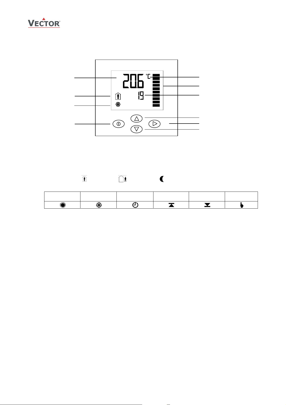
Display and Operation
The operation terminal uses an LCD display and four operation buttons.
1
5
6
7
Legend:
1. 4-digit display of current value, time, control parameter or set point
2. Unit of displayed value, °C, °F, % or none
3. Graphical display of output or input value with a resolution of 10%
4. 4-digit display of current value, time, control parameter or set point
5. Operation modes: Comfort mode, Standby mode, Energy Hold Off
6. Symbols:
Heating Active Cooling Active Schedule Set Direct Acting
7. POWER button: Standard function: Pressing the button less than 2 sec toggles standby and comfort mode.
Pressing the button for more than 2 seconds switches the unit off.
Programming function: ESC function, to return to previous level or ignore changed value
8. UP buttons: increment set points and parameters, select menu options
9. OPTION button: Standard function: If pressed less than 2 sec access for different control modes
If pressed for more than 2 sec starts operation level for advanced users. Change of time schedules, offsets and
heat – cool settings.
Programming function: Acts as Enter to select menu option or accept changed parameter value.
10. DOWN buttons: decrement set points and parameters, select menu options
Active
2
3
4
8
9
Reverse Acting
Active
Cascade
Override
Operation Modes
• Comfort: The unit is in full operation mode. All the control functions are operating according to their setpoints.
The unit displays occupied mode.
• Standby: The set points are shifted according to parameters 1L00 or 2L00. The heating parameter is shifted
down and cooling parameter up. The unit displays unoccupied mode. Outputs are limited to OP04 standby
maximum. For two stages heating or cooling the second stage will not operate while in standby mode. Standby
operation may be disabled with UP06.
• Energy Hold-Off (EHO): The unit is turned off, and "Off" is displayed. However, the inputs are still monitored and
the alarm functions will operate normally.
Activation of operation modes
• Via operation terminal
• Clock (Deluxe version only): Operation modes may automatically be switched according to daytime and weekday.
The clock symbol will be indicated if time programs are activated.
• Infrared Remote Controller (Deluxe version only): use OPR-1 to control the unit remotely
Doc: 70-000002 V1.0, 20101115 © Vector Controls GmbH, Switzerland Page 6
Subject to alteration
Page 7

TCY3-T0121R Operation
Operation of the Terminal Unit
Switching ON
The unit is switched on by pressing the POWER button. It will start up in comfort mode.
Changing between COMFORT and STANDBY
Pressing the POWER button for less than 2 seconds toggles between STANDBY and COMFORT modes. Standby mode may
be disabled with UP06.
Switching OFF
Pressing the POWER button for more than 2 seconds, will switch the unit off. OFF and current time will be displayed in the
LCD for the deluxe unit. Current temperature and OFF is displayed for the basic unit.
Standard display
Standard display is enabled with parameter UP08. This display mode is active if no UP/DOWN or OPTION key has been
pressed during the previous 30 seconds. The contents of the large and small digits may be chosen with parameters UP09
to UP10.
Should Standard display be disabled, the selected loop setpoint will be displayed in the small digits, the associated input
in the large digits and the output in the right hand scale.
Changing of set points
If two control loops are enabled, step through loop 1 and loop 2 by pressing the OPTION/RIGHT button. The large digits
show Lp1 and Lp2 alternately with the set point of that loop shown in small digits. With the desired control loop displayed
change its set point with the UP/DOWN buttons. If only one control loop is enabled press the OPTION/RIGHT button to
display set point in small digits and adjust with UP/DOWN buttons (Lp1 or Lp2 is not shown). Changing of setpoints may
be disabled with UP01.
Override of secondary set point in cascade control
If cascade control is active (for example VAV control), it is possible to override the primary loop and manually set the set
point of the secondary loop. While the secondary loop is displayed change the set point with UP/DOWN keys. The manual
indication will show on the display. (For VAV this would mean the loop is now changed to CAV. This is especially useful
while tuning the VAV system) Pressing the OPTION key to move back to the temperature loop will cancel manual override.
Manual override may be disabled with UP02.
Power Failure
All the parameters and set points are memorized and do not need to be reentered. Depending on UP05 the unit will
remain switched off, switch on automatically or return to the operation mode it was in before the power failure.
Deluxe version only: Timer operation and daytime setting will be retained for 24h. The controller has to be connected to a
power supply for at least 10 hours for the backup function to operate accordingly.
Clock Operation (Deluxe Version)
The TCY3 contains a battery backed up quartz clock. Up to 16 mode changes (STANDBY, COMFORT, OFF) based on
weekdays and time may be programmed. See chapter operation on how to program and assign switch times to the
corresponding loops.
A blinking clock indicates that the time has not been set. This may occur if the time was never set or if the unit was
without power for longer than 24 hours. The time needs to be set in order to allow time programs to operate. See chapter
operation, advanced settings for instructions on how to set the time.
Error messages
The TCY3 may display the following error condition:
Err1: Temperature sensor faulty or missing. The connection to the temperature sensor may be interrupted or the
Err2: The internal humidity sensor is damaged or missing. All outputs connected to this sensor will be set to off mode.
Err3: Problem with the internal real-time clock. Time schedule programs are not operating, time related functions will
temperature sensor is damaged. All outputs connected to this sensor will be set to off mode. Sensor feedback
signals will be set in alarm mode.
Sensor feedback signals will be set in alarm mode.
not be accurate. Clear the error message with OPTION key. If error reappears, replace product.
Doc: 70-000002 V1.0, 20101115 © Vector Controls GmbH, Switzerland Page 7
Subject to alteration
Page 8

TCY3-T0121R Operation
Accessing advanced settings
Pressing the option button for more than three seconds will start the advanced setup menu. The large LCD digits display
SEL. The advanced setup menu Clock setup, Time schedules, Heat / Cool change for 2 pipe systems. The menu may be
left by pressing the POWER key or by not pressing a key for more than 2 minutes.
• Calibration of inputs: SEL is displayed in the large digits and CAL1 or CAL2 in the small. Pressing OPTION will
reveal the current calibration value of the temperature sensor (CAL1) or the analog input (CAL2). Change the
value with the UP/DOWN keys and confirm with OPTION key.
• Heat / Cool change. H-C is displayed in the small LCD. Currently active symbol for heating or cooling show
below. Pressing the OPTION key again toggles Heating – Cooling mode.
Access to Heat/Cool change may be disabled with UP03
Clock and time schedule operations for Deluxe Version only:
• Clock Setup. The current time is displayed in the small digits. Pressing the OPTION button will enter the clock
setup. The minutes are blinking and may be changed with the UP/DOWN keys. Pressing OPTION saves the
minutes and steps to the hours. The hours are blinking. Pressing the OPTION key again will step to the weekday.
DAY1-7 is displayed. Day 1 stands for the first working day (Monday) of a 5-day working week. (See schedule).
Select the day according to current weekday. Pressing Option again saves the settings and moves back to the
SELECT menu.
• Time Schedules: press the option key while Pro is displayed in the small digits. Pro1 is now shown in the large
digits, while the number 1 is blinking. Select time program by using UP/DOWN keys. There is a total of 4 time
programs with each 4 switching times available. Enter the time program by pressing the OPTION key.
1. Activate or deactivate the time program. Choose ON or OFF with the UP/DOWN keys. The following steps will
only be accessible if ON is selected.
2. Select weekday(s) = d1-7, d1-6, d1-5, d6-7, day1, day2, day3, day4, day5, day6, day7. This time schedule
will be active during the selected weekdays. Day 1 stands for Monday, day 2 for Tuesday and so forth.
3. The next steps define the switching mode and time. The bar indicator on the right side shows programming
progress. There are four switch times for each program.
• Select desired operation mode. (no, ON, Eco, OFF), press OPTION to continue
o no = ignores this switching interval
o On = sets operation mode to On and Comfort
o Eco = sets operation mode to On and Standby
o OFF = switches unit Off
• Select switching time 00:00 to 23:45 in 15-minute steps;
press OPTION to continue.
• Repeat above two steps for each switching time.
Access to time schedules may be disabled with UP04
Doc: 70-000002 V1.0, 20101115 © Vector Controls GmbH, Switzerland Page 8
Subject to alteration
Page 9

C
A
d e f g h
i
Operation with OPR-1
The deluxe version may also be operated through an infrared
remote controller.
1. Mode indication, Auto, Dry, Cool, Fan, Heat
2. 2-digit display of setpoint
3. Fan indication
4. 4-digit display of current time or delayed switching time
5. Standby button: Toggles Standby/Comfort mode
6. Mode button, changes operation modes
7. UP/DOWN Button: Set point adjustment buttons
8. FAN Button: Changes fan speed, low – medium – high
or Auto
9. Boost button, activates full output for 5 Minutes
10. Time related buttons: Timer, Hour, Minute
11. POWER Button: Operation mode ON - OFF
c
Switching ON
The unit is switched on by pressing the POWER button. It will start up in comfort mode.
UTO
24
CLOCK
0:00
SLEEP
TCY3-T0121R Operation
MODE
º
BOOST
TIMER
HOUR
MINUTE
j
k
l
11
Changing between COMFORT and STANDBY
Pressing the SLEEP button toggles between STANDBY and COMFORT modes.
Switching OFF
Pressing the POWER while the unit is on, will switch the unit off. The current time will be displayed in the LCD of OPR-1.
Changing of set points
Only the set points for the temperature loop may be changed. Set point range is 15 to 30 °C.
Changing of fan speeds
Repeatedly pressing the fan speed button steps through low, medium, high and automatic fan speeds. Automatic fan
speed will not be activated in FAN ONLY mode.
Boost
Pressing the boost button activates a 5 minute boost. The output will be fully opened for the period of 5 minutes
independent of demand.
Clock settings
The remote controller contains a daytime clock. The receiving TCY3-T0121R controller will adopt the OPR-1’s own clock
whenever it received a command from it.
In order to set the clock in the OPR-1, press HOUR and MINUTE button together until the clock starts blinking. Then set
the correct time with the HOUR and MINUTE buttons. Confirm by pressing the TIMER button.
Delayed switching
The unit may be delayed switched on or off using the timer button. Pressing the timer button once will display Timer ON if
currently in OFF mode or TIMER OFF if currently in ON mode. Set the time when the unit is supposed to switch on or off
using the HOUR and MINUTE keys.
Mode changes
Repeatedly pressing the mode button may activate the following operation modes: HEAT, COOL and FAN ONLY. The mode
change function on the TCY3-T0121R may be disabled using the UP00 parameters.
Doc: 70-000002 V1.0, 20101115 © Vector Controls GmbH, Switzerland Page 9
Subject to alteration
Page 10

TCY3-T0121R Operation
Setting of parameters
The TCY3 is an intelligent controller and can be adapted to fit perfectly into your application. The control operation is
defined by parameters. The parameters are set during operation by using the standard operation terminal.
The parameters are password protected. There are two levels of parameters: User operation parameters for access control
settings and Expert parameters for control functions and unit setup. The passwords for user levels and expert levels are
different. Only control experts should be given the control parameter password.
The parameters can be changed as follows:
1. Press UP and DOWN button simultaneously for three seconds. The display will indicate the firmware version in the
upper large digits and the revision in the lower small digits. Pressing any key will show: CODE.
2. Select a password using UP or DOWN buttons. Dial 009 in order to get access to the user parameters.
Press OPTION after selecting the correct password.
3. Once logged in, the parameter is displayed immediately
4. Select the parameters with the UP/DOWN keys. Change a parameter by pressing the OPTION key. The MIN and
MAX symbols show up and indicate that the parameter may be modified now. Use UP and DOWN key to adjust
the value.
5. After you are done, press OPTION or POWER in order to return to the parameter selection level.
6. Press the POWER key again so as to leave the menu. The unit will return to normal operation if no key is pressed
for more than 5 minutes.
User Parameters (Password 009)
Parameter Description Range Default
UP 00 Enable access to operation modes ON, OFF ON
UP 01 Enable access to set points ON, OFF ON
UP 02 Enable manual control in cascade or fan control mode ON, OFF ON
UP 03 Enable change of heating / cooling mode for 2 pipe systems ON, OFF ON
UP 04 Enable access to time programs: ON, OFF ON
UP 05 State after power failure:
UP 06 Enable standby functionality ON, OFF ON
UP 07 Celsius or Fahrenheit, ON for Fahrenheit, OFF for Celsius ON, OFF OFF (Celsius)
UP 08 User Display: Select display while no key is pressed ON, OFF ON
UP 09 Select contents of Large LCD display in standard mode: 0…9 3
UP 10 Select contents of small LCD display in standard mode 0…9 9, 1
UP 11 Select contents of vertical LCD display in standard mode 0…4 3
UP 12 ON = Display heating & cooling state in standard mode
0 = off, 1 = on, 2 = state before power failure
00 = OFF
01 = Set point Temperature HC
02 = Set point Universal 1
03 = Int. Temperature Input
04 = Ext. Temperature Input
00 = OFF
01 = Analog Input
02 = Humidity Input
OFF = Show heating and cooling while output is active
05 = Analog Input
06 = Humidity Input (-H only)
07 = Analog Output
08 = Floating Output
09 = Clock
03 = Analog Output
04 = Floating Output
0, 1, 2 2
ON, OFF OFF
Doc: 70-000002 V1.0, 20101115 © Vector Controls GmbH, Switzerland Page 10
Subject to alteration
Page 11

T
TCY3-T0121R Engineering Manual
Control Functions
Lp1: Temperature control loop: Signal input: either internal or external passive temperature probe
Lp2: Universal control loop: Signal input: analog input or internal humidity sensor (-H version only)
Each control loop may utilize 6 binary and 2 PID control sequence functions. Control sequences will be activated once
assigned to a physical or logical output.
Manipulation of the set point
Standby set point shift X
point W
is reduced and the cooling set point WC increased by the value of the standby set point shift X
H
Dead Zone Span X
: The dead zone span lies between the heating and the cooling set point.
DZ
Minimum and Maximum Set Point Limits: Limits the adjustable range of the loop set point. The limits for heating and
cooling sequence may be chosen individually.
Cascade Control: The output of the primary control loop determines the set point of the secondary control loop. It is
possible to choose only the direct or reverse sequence or both of them. The output of the set point providing control loop
is spanned between the minimum and maximum set point limits. The set point limits for heating and cooling sequence are
defined individually.
Summer – Winter Compensation: Shift the set point either towards the set point minimum (negative shift) or the set
point maximum (positive shift) depending on an external input signal. This is done to compensate the set point due to a
change in the environment. It is most commonly applied to outside temperature. Summer-Winter compensation is
activated through parameter 1L07 or 2L07.
IP22 selects the compensation input signal, either external temperature or analog input.
The winter compensation is active when the outside temperature drops below the upper limit of winter compensation
IP25. Depending on parameter IP23, the setpoint is now shifted towards the heating setpoint minimum or maximum.
The maximal compensation is reached when the temperature reaches the lower limit IP24. The actual set point will in this
case be equal to the minimum heating set point limit for a negative shift or the maximum set point limit for a positive
shift.
The summer compensation is active when the outside temperature exceeds the lower limit for summer compensation
IP27. Depending on parameter IP26, the setpoint is now shifted towards the cooling setpoint minimum or maximum. It
reaches its maximum when the temperature equals the upper limit IP28.
Example: Summer – Winter compensation active in loop 1. 1L07 = 3
: This function shifts the set point while the operation mode is standby. The heating set
SBY
SBY
.
Setpoint
Doc: 70-000002 V1.0, 20101115 © Vector Controls GmbH, Switzerland Page 11
Subject to alteration
Winter Compensation
1L04
1L02
W
1L01
1L03
IP24
IP23 = ON
IP23 = OFF
Summer Compensation
IP25
IP27
IP26 = ON
IP26 = OFF
[°C, F]
U [V, mA]
IP28
Page 12

T
TCY3-T0121R Engineering Manual
PID-Control
Each loop has one reverse (heating) and one direct (cooling) acting PID sequence.
Heating, Reverse
100
0
YH1, Y
R1
Cooling, Direct
Y
C1, YD1
W
W
XPH
X
SBY
H
XDZ
C
X
PC
X
SBY
[°C, F]
U [V, mA]
Legend:
T, U Input Signal
X
P-band Heating, Direct
PH
X
P-band Cooling, Reverse
PC
X
Dead zone
DZ
X
Standby set point shift
SBY
Set point Heating, Reverse
W
H
W
Set point Cooling, Direct
C
Y
P sequence Heating, Reverse
H1, YR1
Y
P sequence Cooling, Direct
C1, YD1
Proportional Control:
Proportional-band X
the controller. Typical values used are 1 – 1.5K for heating, 2 – 3K for cooling sequences.
The P-band should be extended in case the ID-Part is active, to prevent instability.
: The proportional part is defined through the p-band. A narrow P-band increases the sensitivity of
P
Integral & Differential Control:
The algorithm used reduces the swinging tendency of the control loop and improves a direct approach of the current value
to the setpoint. The ID part is defined by two parameters:
The time interval TI specifies how fast the control sequence reacts. A low value (short interval) increases the swinging
tendency and with it the risk of an instable loop. A high value (long interval) slows than reaction time.
The integral gain factor KI specifies how strong the control sequence reacts. Opposite to TI a high gain factor increases
instability and a low factor delays the response of the controller.
We recommend the following values:
For air based heating systems: TI = 3s, KI = 1.0
For floor heating systems: TI = 5s, KI = 0.5
For air cooling systems: TI = 3s, KI = 1.2
For humidifying systems: TI = 60s, KI = 0.4
For dehumidifying systems: TI = 70s, KI = 0.3
Pressure Control (VAV): TI = 1s, KI = 0.8 (depending on speed of actuator KI varies)
Doc: 70-000002 V1.0, 20101115 © Vector Controls GmbH, Switzerland Page 12
Subject to alteration
Page 13

T
TCY3-T0121R Engineering Manual
Binary Control
Each loop has three reverse- (heating) and three direct- (cooling) acting binary sequences. The offset to the setpoint is
adjustable for each sequence. The switching hysteresis is adjustable per control loop.
Action of stages: The stages may be activated according three different patterns:
One at the time: Only one stage is active at the time. The lower stage will be switched off when the higher stage gets
Cumulative: Multiple stages are active at the same time: The lower stage stays activated when the higher stage
Binary coded: In the first step only the first stage is active; in the second step only the second stage. In the third
Action Stage 1 Stage 2 Stage 3
One at the time Q
Cumulative Q
Binary coded Q
Binary Control
Legend:
ON
OFF
Switching Hysteresis: Defines the difference between switching on and switching off of a digital sequence. A small
hysteresis will increase the number of switching cycles and thus the wear on associated equipment.
Delayed switching. Cumulative Heating/ cooling stages will not switch simultaneously with stage 1, in case of a sudden
demand or at power on. Stage 2 will not start earlier than 5 seconds after stage 1 has been initiated.
active. Example: fan speed control.
switches on. Example: Electrical heating stages
step both stage 1 and stage 2 are switched on. This is used for heating stages. The size of the
second heating stage should be doubled the size of the first heating stage. For example 100W for the
first stage and 200W for the second stage. With two outputs we could create the following steps: 1.
Step 100W, 2. step 200W, 3. step 300W.
H2, QR2
XH
1
1
1
OSH
Q2
Q1+Q2
Q2 Q
Q
C1, QD1
W
W
C
H
XDZ O
1+Q2
Q
SC
Q
C2, QD2
[°C, F]
U [V, mA]
T, U Input Signal
O
Offset Heating, Direct
QH
O
Offset Cooling, Reverse
QC
X
Switching Hysteresis
H
X
Dead zone
DZ
X
Standby set point shift
SBY
W
Set point Heating, Reverse
H
W
Set point Cooling, Direct
C
Q
, QD Binary Output Stage Cooling, Direct
C
, QR Binary Output Stage Heating, Reverse
Q
H
Input Configuration
General
Alarms: Each input features low and high limit alarms. Each alarm is defined with a limit, a hysteresis and an enable
parameter. The limit specifies the input signal level required to trigger the alarm. The hysteresis defines the difference
between input signal and limit required to return the alarm state to normal. Once an alarm is triggered it will be displayed
as ALA1, ALA2, ALA3 and ALA4. Each alarm needs to be acknowledged by pressing the RIGHT key.
ALA1 = Lower limit of the input signal of control loop 1 (temperature) has been reached
ALA2 = Upper limit of the input signal of control loop 1 (temperature) has been reached
ALA3 = Lower limit of the input signal of control loop 2 (universal) has been reached
ALA4 = Upper limit of the input signal of control loop 2 (universal) has been reached
Averaging function: Averaging function is used to prevent unwanted fluctuation of sensor signals. The controller
measures every second the signal inputs. The input signal is now built over a number of measured values. Select how
many values should be used to calculate the averaging signal. Control speed will slow down when a large number of
samples are used for an averaging signal. This should be taken into account when defining the control parameters.
Compensation: Adjust input values if required
Doc: 70-000002 V1.0, 20101115 © Vector Controls GmbH, Switzerland Page 13
Subject to alteration
Page 14

A
p
p
TCY3-T0121R Engineering Manual
Temperature Input
The TCY3 includes an NTC-based passive temperature sensor. A sensor
ccuracy in Kelvin,
Tem
1.0
erature In
ut
of the same type can be connected as alternative control input or as
input for additional functions. The accuracy of the temperature input is
shown in the table to the right. Specified accuracy can only be
guaranteed by using a manufacturer approved temperature sensor. For
0.5
0.2
best results use Sxx-Tn10 sensors.
Choose the active temperature input (intern or extern) of control loop 1
with IP00.
0 50 100
T °C
Additional functions of the external temperature input:
Following additional functions are available, in case the external temperature input is not used as input for control loop 1.
Toggle of Standby and
Comfort operation modes
Remote Enable Opening the external temperature input will force the unit into the OFF operation
Heat-cool changeover with
external switch
Auto changeover with media
temperature sensor
Standby and Comfort modes are controlled through an external contact by connecting
the external temperature input to ground
Activation Delay: Defines the delay the binary contact has to be open before
standby mode is activated.
This function may be used together with key card switches for hotels or motion
detectors for offices.
mode. The operation mode cannot be overridden by using the terminal or time
schedules. Connecting the external temperature input to GND returns control of the
operation mode to the terminal and time schedule. This function may be used as
window contact to prevent loss of energy.
Control heat and cool setting of your controller from a central location by switching a
contact to GND. Note: all ground levels of involved controllers must be the same.
Choose if heat or cool is to be active when contact is open.
The external input may be used to automatically determine heating or cooling mode.
Connect a qualified passive sensor to the external input and measure the temperature
of the supply media. Heating or cooling mode are activated once the supply
temperature is above or below the respective limits. The limits may be defined in
software. Standard is 16°C (60°F) for cooling and 28°C (82°F) for heating.
Universal Input:
The analog input signals may be configured with a jumper to 0-10V, 0-5V and 4-20 mA. The jumper is
located on the front side of the power part. The drawing on the right indicates the jumper placement for each
signal type. The factory setting is 0-10 VDC. Only place the jumper vertically.
The range of the input signal can be specified in software by setting a minimum and a maximum limit. The
limits are in percent of the full range.
The display value of the input signal may be specified according to its measuring range. For example a
pressure sensor has a 4-20 mA output and a pressure range of 0 – 200 Pa. It is possible to transform the
input signal into a different dimension by setting the lower and upper measuring range limit according to the
features of the sensor device. In our example the display will read 100 for a 12 mA signal. Range values
below 100 will have a resolution of 0.5, below 50 of 0.2 and below 25 of 0.1.
AI1
0…10V
█
0…20mA
Humidity Input (-H Version)
The TCY3-T0121R-H includes a capacitive-based humidity sensor with 3% accuracy. The sensor may be used as control
input, as feedback or display input. It will replace the analog input on loop 2, if configured as control input.
RT or contact
Doc: 70-000002 V1.0, 20101115 © Vector Controls GmbH, Switzerland Page 14
Subject to alteration
Page 15

TCY3-T0121R Engineering Manual
Output Configuration
General
An output must be assigned to a function or a control loop using the OP parameter set. Assigning an output to a control
function will automatically activate the respective function. Unassigned functions are not active.
Alarm function
The alarm setting defines how the output should respond to a specific alarm
condition. In case of an alarm the output may be switched on (100%) or off (0%).
The alarm situation takes precedence over operating state and calculated output
Priority for output control
1. Alarm Level High,
2. Operation mode OFF
3. Control function
signal.
Analog Output
AO
The analog output may be configured with jumpers for 0-10 VDC or 0-20 mA control signals. The jumper is
located on the front side of the power part. The drawing on the right indicates the jumper placement for each
signal type. The factory setting is 0-10 VDC. Only place the jumper vertically. Only place one jumper for one
signal. The signal range can be specified in software by setting a minimum and a maximum limit. The limits are
in percent of the full range.
Special functions of the analog output:
0…10V
█
Manual Positions the output directly with a set point. The number of positioning steps can be
selected: 2, 10, 100 steps
Dehumidifying
(only for 4-pipe systems)
The maximum value is taken of both direct acting PID sequences (Cooling and
dehumidifying). Cooling will start to operate if the humidity gets too high, even if there is
no cooling need, thus the heating will be forced to come into play, which in turn
dehumidifies the air.
VAV In the VAV control sequence, at peak cooling the airflow setpoint is the maximum amount
of air the VAV box is set to deliver. It may be adjusted through the maximum limit on the
analog output (OP03). As cooling requirements decrease, airflow dwindles until it reaches
its minimum setpoint. This setpoint will be based on the airflow needed at design cooling
and is typically 10% to 15% of maximum cooling airflow. Minimum airflow can be adjusted
by the minimum limit on the analog output (OP02). When it reaches this minimum, the
system is in its dead band and is neither heating nor cooling. As the system moves into
heating mode, the airflow rate increases until it reaches the maximum airflow required for
heating mode. This is typically 30 to 50% of maximum airflow of cooling mode. The
parameter for this is called VAV function: maximum limitation in heating mode (OP05).
0…20mA
Binary-Function
(AER-C13)
Heating
YH1, Y
100
50
VAV heat max: OP05
0
R1
W
W
C
H
X
DZ
The analog output may be converted into three binary outputs by use of an accessory
(AER-C13). Instead of the PID sequence, the on/off sequence for 3 binary sequences is
Cooling
Y
C1, YD1
AO min: OP02
AO max: OP03
T [°C, F]
U [V, mA]
enabled. The binary output may be enabled for all the lp1 and lp2 sequences.
Switching voltages are fixed to following output levels:
Stage 0 Stage 1 Stage 2 Stage 3
Sensor and setpoint
feedback
0% 40%
Internal humidity and temperature sensor values as well as set points may be transmitted
on the analog outputs. Minimum and maximum value of the feedback value may be set for
70%
100%
loop 1 (Temperature), Loop 2 is fixed to 0…100%. The alarm output level will be activated
in case a sensor is in error mode.
Feedback of floating output The position of the floating output is calculated according to the sum of opening and
closing time of the actuator. The total running time of the actuator must be entered.
Doc: 70-000002 V1.0, 20101115 © Vector Controls GmbH, Switzerland Page 15
Subject to alteration
Page 16

TCY3-T0121R Engineering Manual
Binary Outputs
If OP11 is in the OFF position, DO1 and DO2 may be used as binary outputs. They may be used for binary sequences or
other special functions:
Additional functions oft he binary output:
Dehumidifying
(only for 4-pipe systems)
Operation State (On if
operation state is ON)
Operation State with switch
off delay 60s
Output while demand on
any output, switch off delay
60s
Indication of the fan symbol
The maximum value is taken of both direct acting sequences of LP1 and LP2 (Cooling and
dehumidifying). Cooling will start to operate if the humidity gets too high, even if there is
no cooling need, thus the heating will be forced to come into play, which in turn
dehumidifies the air.
The output is ON if either comfort or standby mode are active. In energy hold off mode
(EHO) the output is off.
The output is ON if either comfort or standby mode are active. In energy hold off mode
(EHO) the output is off with a switch off delay of 60s. This is required for fan supported
heating or cooling coils with mold protection.
The output is ON if demand exists on any other output. The output switches off with a
fixed delay of 60s if there is no more demand. This function is usefull for fan supported
heating or cooling devices.
By enabling this function, the fan symbol is shown on the display whenever DO1 is active.
Floating Outputs
Enabling OP11 changes DO1 and DO2 into a floating output for a PID loop. In this case the running time of the actuator
needs to be specified. Running time is defined as the time required for the actuator to run from fully open to fully closed
or vice versa. Actuators with a fixed running time are recommended. Once fully open or fully closed the running time for
the actuator is extended for a full run time cycle. This will allow the actuator position to be synchronized in case it has
been moved during off time or an actuator with variable running time was used.
Switching difference on floating output: Use the Switching difference parameter to reduce the switching frequency of the
actuator. The actuator will only move, if the difference to the current actuator position is larger than this parameter.
Doc: 70-000002 V1.0, 20101115 © Vector Controls GmbH, Switzerland Page 16
Subject to alteration
Page 17

TCY3-T0121R Engineering Manual
Configuration of controller
Proceed in the following steps in order to adapt the controller to its application:
1. Set jumpers for inputs and outputs
2. Connect power supply and inputs
3. Program input parameters (IP)
4. Program control parameters (1L or 2L)
5. Program output parameters (OP)
6. Test function of unit
7. Switch off power
8. Connect outputs
9. Test control loop
10. Set user settings (UP)
Configuration parameters for firmware version 3.1
The TCY3-T0121R can be adapted to a wide variety of applications. The adaptation is done through parameters. The
parameters can be changed on the unit without the need of additional equipment.
Identifying the firmware version
The parameters and functionality of controller depend on its firmware version and revision. It is therefore important to use
a matching product version and parameter set. The Firmware version and revision version can be found when pressing
simultaneously the S and T keys during several seconds. On the upper 7 segment display, the firmware version can be
found, on the lower 7 segment display the current revision index (or “sub-version”).
Control Parameters (password 241)
Warning! Only experts should change these settings! The parameters are grouped according to following control modules.
Module Description
1L Loop 1: Heat/Cool: Temperature Input 1
2L Loop 2: Universal: Analog Input
IP Input configuration
OP Output configuration
The parameters can be changed as follows:
7. Press UP and DOWN button simultaneously for three seconds. The display will indicate the firmware version in the
upper large digits and the revision in the lower small digits. Pressing any key will show: CODE.
8. Select a password using UP or DOWN buttons. Dial 0241 in order to get access to the engineering parameters.
Press OPTION after selecting the correct password.
9. Once logged in the parameter group can be selected with the UP and DOWN key. Enter the group with the
OPTION key.
10. Once the group is selected, the parameter is displayed immediately
11. Select the parameters with the UP/DOWN keys. Change a parameter by pressing the OPTION key. The MIN and
MAX symbols show up and indicate that the parameter may be modified now. Use UP and DOWN key to adjust
the value.
12. After you are done, press OPTION or POWER in order to return to the parameter selection level.
13. Press the POWER key again so as to leave the menu and return to the group selection. Press POWER while in the
group selection to return to normal operation.
14. The unit will return to normal operation if no key is pressed for more than 5 minutes.
Doc: 70-000002 V1.0, 20101115 © Vector Controls GmbH, Switzerland Page 17
Subject to alteration
Page 18

TCY3-T0121R Engineering Manual
Control parameters Temperature Input (Loop 1)
Parameter Description Range Default
1L 00 Standby set point shift 0…100° 5.0°C (10°F)
1L 01 Minimum set point limit for heating -40…215°C 10°C (50°F)
1L 02 Maximum set point limit for heating -40…215°C 28°C (82°F)
1L 03 Minimum set point limit for cooling -40…215°C 18°C (64°F)
1L 04 Maximum set point limit for cooling -40…215°C 34°C (92°F)
1L 05 Dead zone between heating & cooling set point XDZ 0…100° 1.0° (2°F)
1L 06 Cascade Control:
Set point of this loop provided by a PID sequence of loop 2.
0 = No cascade control
1 = Setpoint provided by reverse sequence of LP2
2 = Setpoint provided by direct sequence of LP2
3 = Setpoint provided by reverse and direct sequence of LP2
1L 07 Summer – Winter compensation
0 = Disabled
1 = Winter Compensation only
2 = Summer compensation only
3 = Winter and summer compensation
1L 08 Automatic change of Heat / Cool setting by demand
OFF = Manual (2-pipe)
ON = Automatic (4-pipe)
0…3 0
0…3 0
ON, OFF OFF
PID Control Sequence
Parameter Description Range Default
1L 09 P – band heating XPH 0…100° 2.0°C (4.0°F)
1L 10 P – band cooling XPC 0…100° 2.0° (4.0°F)
1L 11 KIH, Integral gain heating, in 0.1 steps,
0 disables ID part
low value = slow reaction
high value = fast reaction
1L 12 KIC, Integral gain cooling, in 0.1 steps, 0 disables I part 0…25.5 0.0
1L 13 TI interval time speed: OFF = Seconds, ON = Minutes ON, OFF OFF (sec)
1L 14 TI, measuring interval integral
low value = fast reaction
high value = slow reaction
0…25.5 0.0
0…255 1 sec
Digital Control Sequence
Parameter Description Range Default
1L 15 Action of stages
0 = Cumulative: 1. Q
1 = Single: 1. Q
2 = Digital: 1. Q
1L 16 Offset heating stage 1: QH1 0…100° 0.0° (0.0°F)
1L 17 Offset heating stage 2: QH2 0…100° 2.0° (4.0°F)
1L 18 Offset heating stage 3: QH3 0…100° 4.0° (8.0°F)
1L 19 Offset cooling stage 1: QC1 0…100° 0.0° (0.0°F)
1L 20 Offset cooling stage 2: QC2 0…100° 2.0° (4.0°F)
1L 21 Offset cooling stage 3: QC3 0…100° 4.0° (8.0°F)
1L 22 Switching Hysteresis XH 0…100° 0.5° (1.0°F)
1L 23 Delay Switching on / off 0…255s 10s
1L 24 Delay Heat / Cool change over 0…255 Min 5 Min
, 2. QH1+QH2
H1
, 2. QH2
H1
, 2. QH2, 3. QH1 + QH2
H1
0…2 0
Doc: 70-000002 V1.0, 20101115 © Vector Controls GmbH, Switzerland Page 18
Subject to alteration
Page 19

TCY3-T0121R Engineering Manual
Control parameters Analog Input
Parameter Description Range Default
2L 00 Standby set point shift Acc input 0%
2L 01 Minimum set point limit for reverse Acc input 0%
2L 02 Maximum set point limit for reverse Acc input 100%
2L 03 Minimum set point limit for direct Acc input 0%
2L 04 Maximum set point limit for direct Acc input 100%
2L 05 Dead zone between reverse & direct set point XDZ Acc input 0%
2L 06 Cascade Control: Setpoint of LP2 provided by a PID sequence of LP1.
0 = No cascade control
1 = Setpoint provided by heating sequence of LP1
2 = Setpoint provided by cooling sequence of LP1
3 = Setpoint provided by heating and cooling seq. of LP1
2L 07 Summer – Winter compensation
0 = Disabled
1 = Winter Compensation only
2 = Summer compensation only
3 = Winter and summer compensation
2L 08 Direct / Reverse related to Heat / Cool setting
OFF = not related
ON = related
0…3 0
0…3 0
ON, OFF OFF
PID Control Sequence
Parameter Description Range Default
2L 09 P – band reverse XPH Acc input 10%
2L 10 P – band direct XPC Acc input 10%
2L 11 KIH, Integral gain heating, in 0.1 steps,
0 disables ID part
low value = slow reaction
high value = fast reaction
2L 12 KIC, Integral gain cooling, in 0.1 steps, 0 disables I part 0…25.5 0.0
2L 13 TI interval time speed: OFF = Seconds, ON = Minutes ON, OFF OFF (sec)
2L 14 TI, measuring interval integral
low value = fast reaction
high value = slow reaction
0…25.5 0.0
0…255 1 sec
Digital Control Sequence
Parameter Description Range Default
2L 15 Action of stages
2L 16 Offset heating stage 1: QH1 Acc input 0%
2L 17 Offset heating stage 2: QH2 Acc input 10%
2L 18 Offset heating stage 3: QH3 Acc input 20%
2L 19 Offset cooling stage 1: QC1 Acc input 0%
2L 20 Offset cooling stage 2: QC2 Acc input 10%
2L 21 Offset cooling stage 3: QC3 Acc input 20%
2L 22 Switching Hysteresis XH Acc input 5%
2L 23 Delay Switching on / off 0…255s 10s
0 = Cumulative: 1. Q
1 = Single: 1. Q
2 = Digital: 1. Q
, 2. QH2
H1
, 2. QH2, 3. QH1 + QH2
H1
, 2. QH1+QH2
H1
0…2 0
Doc: 70-000002 V1.0, 20101115 © Vector Controls GmbH, Switzerland Page 19
Subject to alteration
Page 20

TCY3-T0121R Engineering Manual
Temperature Input configuration
Parameter Description Range Default
IP 00 TI1: Control input of loop 1:
OFF = Internal sensor
ON = External sensor
IP 01 TI1: Samples taken for averaging control signal
IP 02 TI1: Calibration
IP 03 Alarm 1: Alarm for lower limit of temperature input of LP1
OFF = Not active
ON = Active
IP 04 Alarm 1 low limit of temperature input
IP 05 Alarm 1 Hysteresis for alarm setback
IP 06 Alarm 2: Alarm for upper limit of temperature input of LP1
OFF = Not active
ON = Active
IP 07 Alarm 2 high limit of temperature input
IP 08 Alarm 2 Hysteresis for alarm setback
ON, OFF OFF
1…255 10
-10…10 0
OFF, ON OFF
-40…215 °C 5°C (40°F)
0…100 ° 5°C (10°F)
OFF, ON OFF
-40…215 °C 50°C (122°F)
0…100 ° 5°C (10°F)
Analog Input configuration
Parameter Description Range Default
IP 09 AI1: Calibration -10…10 0
IP 10 AI1: Minimum limitation of input signal 0 – Max % 0 %
IP 11 AI1: Maximum limitation of input signal Min – 100% 100%
IP 12 AI1: Lower universal sensor measuring range limit -50…Max 0
IP 13 AI1: Upper universal sensor measuring range limit Min…205 100
IP 14 AI1: Samples taken for averaging control signal 1…255 3
IP 15 AI1: Unit & range of analog input:
0 = no unit
1 = %
2 = °C / °F
3 = x10
4 = x100
0 – 4 1
Alarms 3 and 4 follow control input of Loop 2
Parameter Description Range Default
IP 16 Alarm 3: Alarm for lower limit of universal input of LP2
OFF = Not active
ON = Active
IP 17 Alarm 3 low limit of universal input Acc input 0%
IP 18 Alarm 3 Hysteresis Acc input 5%
IP 19 Alarm 4: Alarm for upper limit of universal input of LP2
OFF = Not active
ON = Active
IP 20 Alarm 4 high limit of universal input Acc input 100%
IP 21 Alarm 4 Hysteresis Acc input 5%
OFF, ON OFF
OFF, ON OFF
Summer – Winter Compensation
Parameter Description Range Default
IP 22 Selection of Compensation Input
OFF = Thermistor Input TI
ON = Analog Input AI
IP 23 Winter Compensation:
OFF = setpoint is shifted negative to lower setpoint limit
ON = setpoint is shifted positive to upper setpoint limit
IP 24 Winter Compensation (Setpoint shift with low compensation signal)
Lower Limit: input signal with maximum setpoint shift
IP 25 Winter Compensation (Setpoint shift with low compensation signal)
Upper Limit: Input signal at begin of setpoint shift.
IP 26 Summer Compensation:
OFF = setpoint is shifted negative to lower setpoint limit
ON = setpoint is shifted positive to upper setpoint limit
IP 27 Summer Compensation (Setpoint shift with high compensation signal)
Lower Limit: input signal at begin of setpoint shift
IP 28 Summer Compensation (Setpoint shift with high compensation signal)
Upper Limit: Input signal with maximum setpoint shift.
IP 29 Hot / Cool Symbol while compensation is active
OFF= Hide symbol
ON= Show symbol
ON, OFF OFF
ON, OFF OFF
-40…215 °C -30°C (-22°F)
-40…215 °C 0°C (32°F)
ON, OFF ON
-40…215 °C 30°C (86°F)
-40…215 °C 40°C (104°F)
ON, OFF OFF
Doc: 70-000002 V1.0, 20101115 © Vector Controls GmbH, Switzerland Page 20
Subject to alteration
Page 21

TCY3-T0121R Engineering Manual
Humidity Sensor Configuration (-H Version)
Parameter Description Range Default
IP 30 Humidity Sensor is Control Input of Loop 2 ON, OFF OFF
IP 31 Humidity Sensor Calibration -10…10 0
IP 32 Samples taken for averaging control signal 1…255 10
Remote Control
Parameter Description Range Default
IP 33 Configuration of remote control input (TI EXT)
0 = no remote control
1 = Occupation sensor – Comfort / Standby
2 = Occupation sensor – Comfort / Off
3 = Heat / Cool change by open contact. Contact open = Heat
4 = Heat / Cool change by open contact. Contact open = Cool
5 = Auto change over depending on supply temperature
IP 34 Activation delay (Minutes) = the time the binary input needs to be open
before standby/off mode is activated.
IP 35 Auto Change Over limit cooling -40…215 °C 16°C (60°F)
IP 36 Auto Change Over limit heating -40…215 °C 28°C (82°F)
0…5 0
0…255 min 5
Analog Output
Parameter Description Range Default
OP 00 AO1: Selection of control loop or special function
OP 01 AO1: Configuration of output signal depending on OP00
OP 02 AO1: Minimum limitation of output signal 0 – Max % 0
OP 03 AO1: Maximum limitation of output signal Min – 100% 100%
OP 04 AO1: Maximum limitation in standby mode 0 – 100 % 50%
OP 05 AO1: VAV function maximum limitation in heating mode 0…100% 50%
OP 06 AO1: Binary function – Convert AO with use of accessory to three binary
OP 07 AO1: Choose alarm
OP 08 AO1: Action in case of alarm
OP 09 Temperature feedback minimum temperature -40…215 °C 0°C (32°F)
OP 10 Temperature feedback maximum temperature -40…215 °C 50° (122°F)
0 = OFF
1 = Loop 1
2 = Loop 2
3 = Dehumidify in 4 pipe systems
(Max LP1 cooling and LP2 direct acting)
4 = Manual override (0 – 100%)
5 = Feedback of temperature input or set point
6 = Feedback of floating output
If OP00 = 1,2 (control loop 1 or 2) select sequence:
0 = Heating, Reverse Y
1 = Cooling, Direct YC1, Y
2 = Heating and Cooling (2 pipe system), YH1 + YC1, YR1 + Y
3 = VAV function
If OP00 = 4 (manual override) Choose Manual override steps:
0 = 0…100%
1 = 0…10
2 = ON/OFF
If OP00 = 5 (Feedback), select feedback source:
0 = Temperature input loop 1 (acc IP00)
1 = Set point loop 1
2 = Set point loop 2
3 = Humidity sensor (-H Version)
4 = Analog input
outputs with following switching steps: 0, 30, 70, 100%
0 = no action
1 = TI1 ALA1: low temperature limit
2 = TI1 ALA2: high temperature limit
3 = TI1 ALA1 and ALA2: low or high temperature alarm active
4 = AI1 ALA3: low signal limit
5 = AI1 ALA4: high signal limit
6 = AI1 ALA3 and ALA4 low or high signal alarm active
7 = Any alarm active (ALA1 – ALA4)
OFF = close (Output is off 0%)
ON = open output (Output is on 100%)
, Y
H1
R1
D1
D1
0 – 6 1
0 – 4 0
ON, OFF OFF
0 - 7 0
ON, OFF OFF
Doc: 70-000002 V1.0, 20101115 © Vector Controls GmbH, Switzerland Page 21
Subject to alteration
Page 22

TCY3-T0121R Engineering Manual
Floating Output
Parameter Description Range Default
OP 11 FO1: Enable Floating Output (DO1, DO2 Floating)
OP 12 FO1: Selection of control loop or special function
OP 13 FO1: Configuration of output signal depending on OP12
OP 14 FO1: Running Time (Time to run from Open to Close) 0 – 1275 s 90s
OP 15 FO1: Switching difference for floating signal 0 – 100% 5 %
OP 16 FO1: Choose alarm
OP 17 FO1 Action in case of alarm
OFF = DO1, DO2 are two binary outputs
ON = DO1, DO2 are one floating output DO1 = open, DO2 = close
0 = OFF
1 = Loop 1
2 = Loop 2
3 = Dehumidify in 4 pipe systems (Max LP1 cooling and LP2 direct acting)
4 = Manual override (0 – 100%)
If OP12 = 1,2 (control loop 1 or 2) select sequence:
0 = Heating, Reverse Y
1 = Cooling, Direct YC1, YD1
2 = Heating and Cooling (2 pipe system), Y
If OP12 = 4 (manual override) Choose Manual override steps
0 = 0…100%
1 = 0…10
2 = ON/OFF
0 = no action
1 = TI1 ALA1: low temperature limit
2 = TI1 ALA2: high temperature limit
3 = TI1 ALA1 and ALA2: low or high temperature alarm active
4 = AI1 ALA3: low signal limit
5 = AI1 ALA4: high signal limit
6 = AI1 ALA3 and ALA4 low or high signal alarm active
7 = Any alarm active (ALA1 – ALA4)
OFF = close output
ON = open output
, Y
H1
R1
+ YC1, YR1 + YD1
H1
ON, OFF OFF
0 – 4 0
0 – 2 0
0 – 7 0
ON, OFF OFF
Doc: 70-000002 V1.0, 20101115 © Vector Controls GmbH, Switzerland Page 22
Subject to alteration
Page 23

TCY3-T0121R Engineering Manual
Digital Output 1
Parameter Description Range Default
OP 18 DO1: Configuration Digital Output (only if floating disabled)
0 = OFF
1 = Loop 1
2 = Loop 2
3 = Dehumidifying, Max of loop 1 cooling and loop 2 direct
4 = Operation State (On if operation state is ON)
5 = Operation State with switch off delay 60s
6 = Output while demand on any output, switch off delay 60s
OP 19 DO1: Configuration of action (if Loop 1 or Loop 2)
0 = 1. Stage heating, reverse Q
1 = 1. Stage cooling, direct Q
2 = 1. Stage heating and cooling, reverse and direct, QH1+Q
3 = 2. Stage heating, reverse QH2, Q
4 = 2. Stage cooling, direct, QC2, Q
5 = 2. Stage heating and cooling, reverse and direct, Q
, QR1
H1
, Q
C1
D1
R2
D2
OP 20 DO1: Choose alarm
0 = no action
1 = TI1 ALA1: low temperature limit
2 = TI1 ALA2: high temperature limit
3 = TI1 ALA1 and ALA2: low or high temperature alarm active
4 = AI1 ALA3: low signal limit
5 = AI1 ALA4: high signal limit
6 = AI1 ALA3 and ALA4 low or high signal alarm active
7 = Any alarm active (ALA1 – ALA4)
OP 21 DO1: Action in case of alarm
OFF = close output
ON = open output
H2
C1
+ QC2
0…6 0
0…5 0
0 – 7 0
ON, OFF OFF
Digital Output 2
Parameter Description Range Default
OP 22 DO2: Configuration Digital Output (only if floating disabled)
0 = OFF
1 = Loop 1
2 = Loop 2
3 = Dehumidifying, Max of loop 1 cooling and loop 2 direct
4 = Operation State (On if operation state is ON)
5 = Operation State with switch off delay 60s
6 = Output while demand on any output, switch off delay 60s
OP 23 DO2: Configuration of action (if Loop 1 or Loop 2)
0 = 1. Stage heating, reverse Q
1 = 1. Stage cooling, direct Q
2 = 1. Stage heating and cooling, reverse and direct, QH1+Q
3 = 2. Stage heating, reverse QH2, Q
4 = 2. Stage cooling, direct, QC2, Q
5 = 2. Stage heating and cooling, reverse and direct, Q
, QR1
H1
, Q
C1
D1
R2
D2
H2
C1
+ QC2
OP 24 DO2: Choose alarm
0 = no action
1 = TI1 ALA1: low temperature limit
2 = TI1 ALA2: high temperature limit
3 = TI1 ALA1 and ALA2: low or high temperature alarm active
4 = AI1 ALA3: low signal limit
5 = AI1 ALA4: high signal limit
6 = AI1 ALA3 and ALA4 low or high signal alarm active
7 = Any alarm active (ALA1 – ALA4)
OP 25 DO2: Action in case of alarm
OFF = close output
ON = open output
OP 26 Display Fan Symbol while DO1 active ON, OFF OFF
0…6 0
0…5 0
0 - 7 0
ON, OFF OFF
Doc: 70-000002 V1.0, 20101115 © Vector Controls GmbH, Switzerland Page 23
Subject to alteration
 Loading...