

Page 1
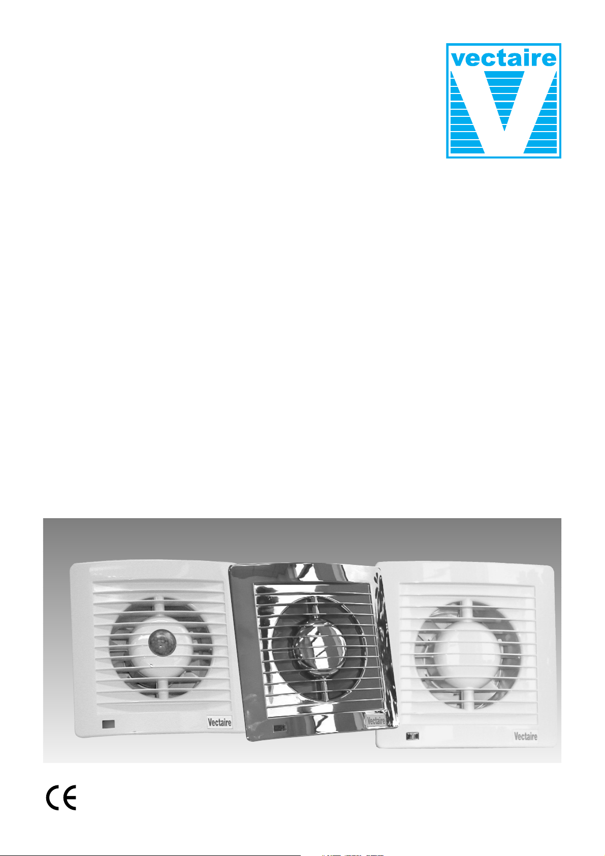
"AS10Plus"
High Pressure
Slimline Axial Fans
Installation and Operating Instructions
• 10 models
standard
with timer
with humidistat and timer
Passive Infra Red
• with white and chrome front covers
• for toilets, bathrooms and shower-rooms
• wall, ceiling or panel installation
쓑
IPX4
Page 2
"AS10Plus - HIGH PRESSURE, SLIMLINE AXIAL FANS
INSTALLATION and OPERATING INSTRUCTIONS
PLEASE READ THE FOLLOWING INSTRUCTIONS VERY CAREFULLY BEFORE USING THE
PRODUCT. THE MANUFACTURER WILL NOT BE HELD RESPONSIBLE AND DECLINES ANY AND
ALL LIABILITY FOR DAMAGE CAUSED TO PERSONS OR PROPERTY DUE TO IMPROPER USE
WITH REFERENCE TO THE PRECAUTIONS OUTLINED IN THIS MANUAL.
THIS MANUAL MUST ALWAYS BE READILY AVAILABLE.
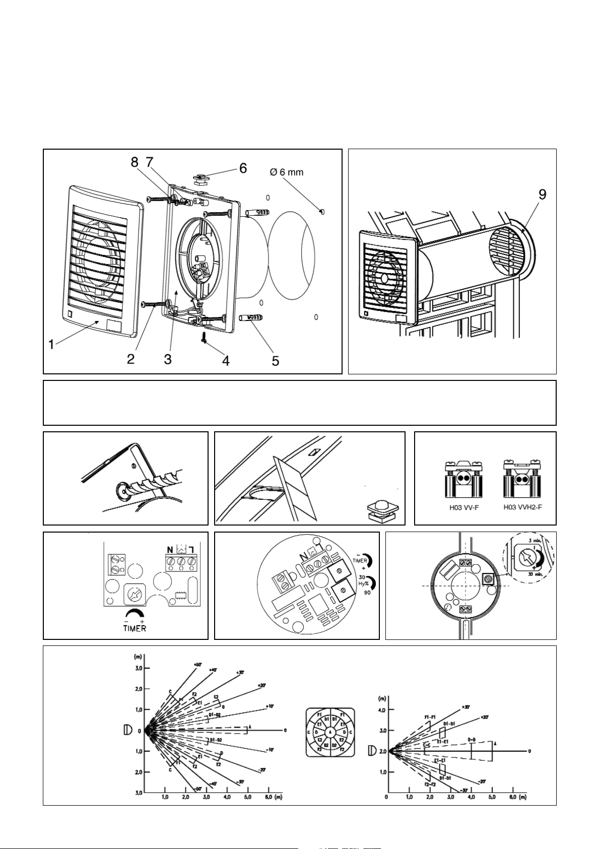
1. Front Cover
2. Wall Fixing Screws
3. Motor Fan Assembly
4. Front Cover Fixing Screw
5. Wall Plug
6. Cable Grommet
7. Cable Clamp
8. Cable Fixing Screws
9. Outside Grille (not supplied)
Fig 5 -
Cable Type
Fig 6 Timer
Adjustment 'T' Models
Fig 7 Humidistat/
Timer
Adjustment 'HT' Models
Fig 3 - Rear Cable
Knockout
Fig 2 - Wall
Installation
Fig 1 - Exploded
Diagram
Fig 4- Top Cable
Knockout
cable grommet
- MUST be used
Fig 8 Timer Adjustment
- 'PIR' Models
Fig 9 PIR Detection
Area
Page 3
"AS10
Plus
" - HIGH PRESSURE, SLIMLINE AXIAL FANS -
INSTALLATION INSTRUCTIONS and OPERATING INSTRUCTIONS
THE RANGE
AS10
Plus:
95m3/hr, 40Pa, 230v, 50Hz, 14w, 31.4dbA
"AS10
Plus
" 4"/10cm slimline axial fans are for exhausting directly outside or through ducting up to 6m long. Models
(Cr) available with Chrome front cover. They are suitable for wall, panel or ceiling installation.
AS10
Plus:
standard version operated by means of a remote switch.
AS10T
Plus:
with integral overrun timer - the fan should be operated by a remote switch which can also serve to
switch the room light on and off. After the light is switched off, the fan will continue to operate for a minimum of 3
minutes (adjustable to a maximum of 25 minutes) by turning the trimmer (Fig 6) in a clockwise direction.
AS10HT
Plus:
with integral humidistat and overrun timer - the adjustable, electronic humidistat is pre-set so that
the fan will operate automatically when the moisture content in the room reaches a pre-set level of relative humidity. The fan will continue to run until the relative humidity falls below the pre-set level. This level can be adjusted by
turning the trimmer (Fig 7) on the fan. This fan can be operated by a remote switch or light switch allowing operation of the fan independently of the humidistat (the neon indicator on the front will light when the fan is operating in
this mode). The overrun timer, which will always make the fan continue to operate for the pre-set length of time
even after it has been manually switched off, can be adjusted as described above.
AS10PIR
Plus
: This fan has an integral sensor and overrun timer. The fan will start to operate automatically when
it detects the presence of a person. After the room is vacated, the fan will continue to operate for a minimum of 3
minutes (adjustable to a maximum of 25 minutes) by turning the trimmer in an anti-clockwise direction (Fig 8).
IMPORTANT - SITING INFORMATION
1. For optimum performance your fan should be installed as high as possible.
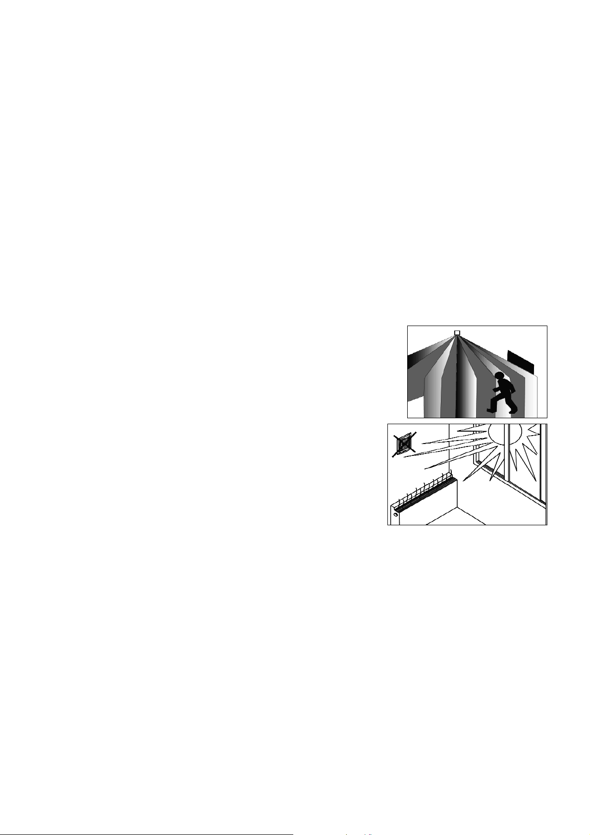
2. PIR models should be installed at a minimum height of 2.3m (see Fig 9 and
Figs 10 and 11 - right) and should be away from a heat source (such as a
heater), any direct light (sunlight, lamp etc) or any air conditioning unit. Care
should be taken to ensure that the sensor is free of any obstruction (such as a
cupboard).
3. The fan must not be used in an ambient temperature higher than 40OC.
4. Your fan must not be exhausted into a duct which is already used for any other
purpose.
5. The room where the fan is installed must have an adequate supply of air
to ensure correct operation (see Approved Document F1 2006 for guidance).
6. If ducting is used, ensure that it is not blocked.
7. An adequate supply of fresh air must be provided if the fan is to be fitted
into a room containing a fuel burning appliance which is not of the balanced flue type (UNI CIG7129).
8. Installation must be carried out by qualified personnel. Incorrect installa-
tion can cause damage to people, animals or property for which the manufacturer cannot be held responsible.
9. If you have any doubts concerning this product, please contact your supplier.
IMPORTANT - ELECTRICAL INFORMATION
1. All electrical connections must comply with current IEE wiring regulations. The fan is a fixed appliance, and the
electrical supply must therefore be by a fixed wired and fused (3 amp) spur incorporating a double or triple pole
switch with contact openings of at least 3mm. Use twin conductor cable of at least 1mm
3
in section (Fig 5).
2. Your fan is double insulated and does not require earthing.
3. The fan complies with current electrical safety regulations (IE64, CENELEC 384), including EEC Directive
EMC89/336 concerning the suppression of radio interference and electromagnetic compatibility.
4. The fan must not be used as a switch for water heaters, stoves etc.
5. It is recommended that the installation be carried out by a qualified electrician.
6. The printed circuit board in these fans has been protected to make it compatible with the majority of fluorescent
fittings available on the market today. However, it is impossible to be aware of all new products introduced. We
suggest, therefore, that you contact your supplier to establish the compatibility of any fluorescent fittings you
intend to use.
INSTALLATION INSTRUCTIONS
1. Remove all packing material and check that your fan has not been damaged in transit.
2. Check that your electrical voltage and frequency correspond with those marked on the fan rating label.
3. Check the location of existing wiring for ease of connection and make the electrical connections as in the fol-
lowing Wiring Instructions.
4. Cut 100mm hole (allowing, if necessary, for the thickness of any ducting used).
Fig 11 -
PIR
Siting
Fig 10 -
PIR Detection
Area
Page 4
5. Remove front fan front cover (1) by loosening front cover fixing screw (4).
6. Use Motor Fan Assembly (3) as template to mark drill holes.
7. Drill fixing holes, and fix Motor Fan Assembly with screws and plugs provided
8. Connect incoming wiring supply.
9. Replace front cover (1).
WIRING INSTRUCTIONS
1. Ensure that the mains electrical supply is switched off during the installation of the fixed wiring spur.
2. The fan must be connected to a single phase mains power supply network of the voltage and frequency
indicated on the rating label.
3. The installation must conform to current Building Regulations and IEE Wiring Regulations.
4. The mains supply cable can be inserted through the rear or top or the fan. If cable goes through top of fan, the
cable grommet must be used.(Fig 4)
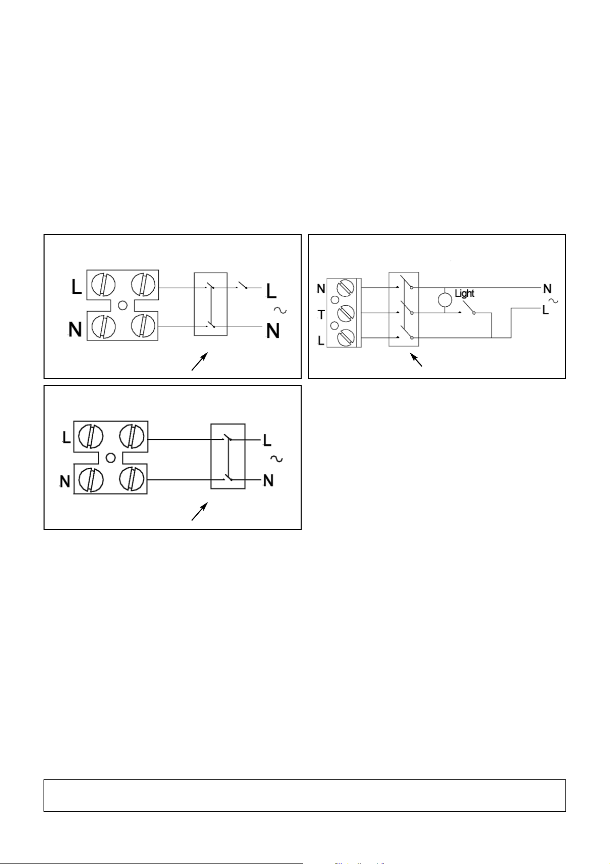
5. With the front cover (1) removed, connect incoming cable to terminal block as follows:
6. Neon light will show when fan is running.
7. Replace front cover (1).
CLEANING AND MAINTENANCE
1. Before carrying out any maintenance or cleaning operation, switch off the fan and disconnect it from the main
power supply.
2. The Front Cover (1) can be cleaned with mild detergent or water. Ensure that it does not come into contact
with any kind of liquid or solvent.
3. The Motor Fan Assembly (3) can be cleaned with a dry cloth or soft brush.
4. Electrical parts cannot be cleaned.
5. Ensure that the fan does not come into contact with any liquid or solvent. Should this occur, contact a quali-
fied electrician before reassembling it
.
Vectaire Ltd, Lincoln Road, Cressex Business Park, High Wycombe, Buckinghamshire, HP12 3RH
Tel: +44 (0)1494 522333. Fax: +44 (0)1494 522337. Email: [email protected]
AS10Plus/1/04/07
AS10
Plus
with remote switch AS10T
Plus
via light switch (or remote switch)
AS10HT
Plus
via light switch (or remote switch)
Triple Pole Isolator
Double Pole Isolator
AS10HT
Plus
humidistat only
AS10PIR
Plus
Double Pole Isolator
 Loading...