

Page 1
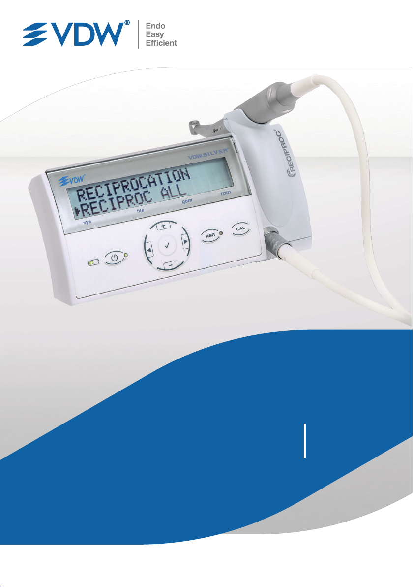
VDW.SILVER
RECIPROC
®
®
Gebrauchsanweisung
vdw-dental.com
Page 2

Herzlichen Glückwunsch zum Kauf des
VDW.SILVER®RECIPROC® Endomotors.
de
Endodontische Produkte und Dienstleistungen sind das
Kerngeschäft der VDWGmbH. Die kontinuierliche enge
Zusammenarbeit mit internationalen Universitäten und
Endodontologen ermöglicht uns die Entwicklung von
innovativen Konzepten, Produkten und Systemen, welche
die Arbeit von Zahnärzten vereinfachen, erleichtern und
effektiver machen.
®
Mit dem VDW.SILVER
RECIPROC® Endomotor haben Sie
ein Produkt erworben, das mit größter Sorgfalt entwickelt
und getestet wurde und damit in Funktion und Bedienung
auch höchsten Ansprüchen gerecht wird.
Die Gebrauchsanweisung ist auf Anfrage in weiteren
Sprachen erhältlich.
Diese Gebrauchsanweisung ist mit der größtmöglichen
Sorgfalt erstellt. Dennoch lassen sich trotz aller Bemühungen Fehler nie vollständig ausschließen. Für Verbesserungsvorschläge sind wir jederzeit dankbar.
Bitte wenden Sie sich in diesem Fall an die VDWGmbH.
VDWGmbH
Bayerwaldstr. 15
81737 München
Deutschland
2
Telefon +49 89 62734-0
Fax +49 89 62734-304
[email protected]
www.vdw-dental.com
Page 3

Inhaltsverzeichnis
3
1. Vor der Verwendung .......................................4
2. Symbole ...........................................................5
2.1. In dieser Gebrauchsanweisung verwendete
Symbole ...........................................................5
2.2. Auf Verpackung, Gerät und Komponenten
verwendete Symbole .......................................5
3. Verwendungszweck, vorgesehener
Anwenderund Patientenpopulation ...............6
4. Kontraindikationen .........................................6
5. Warnhinweise ................................................6
6. Vorsichtsmaßnahmen .....................................7
7. Unerwünschte Wirkungen ..............................7
8. Einrichtung Schritt für Schritt ........................7
8.1. Gelieferte Komponenten und Zubehör .............8
8.2. Erste Schritte ...................................................9
8.2.1. Vorbereitung .....................................................9
8.2.2. Übersicht der Anschlüsse ..................................9
8.2.3. Ladegerät .......................................................10
8.2.4. Mikromotor, VDW6:1 Winkelstück und
Fußschalter .....................................................11
8.2.5. Akku ...............................................................11
8.3. Benutzeroberfläche........................................12
8.3.1. Tastenfeld .......................................................12
8.3.2. Display ............................................................13
8.3.3. Fußschalter .....................................................13
8.3.4. Akustische Signale ..........................................14
8.3.5. Feilenbibliothek ...............................................14
8.4. Betrieb ...........................................................15
8.4.1. Einschalten, Standby-Modus, Ausschalten .......15
8.4.2. CAL: Kalibrierung ............................................16
8.4.3. ASR: Automatic Stop Reverse ..........................16
8.5. Auswahl Feilensysteme/Feilen ......................17
8.5.1. Rotationsmodus ..............................................17
8.5.2. Änderung von Drehmoment und Drehzahl
(nurim Rotationsmodus) .................................18
8.5.3. Dr’sChoice (nur im Rotationsmodus)...............19
8.5.4. Alternierender Modus ......................................19
8.6. Werkseinstellungen .......................................20
9. Reinigung, Desinfektion und Sterilisation ...20
9.1. Vorbehandlung (nach jeder Verwendung
durchzuführen) ..............................................21
9.2. Manuelle Reinigung und Desinfektion ...........22
9.3. Inspektion/Wartung .......................................23
9.4. Verpackung ....................................................23
9.5. Sterilisation ....................................................23
9.6. Aufbewahrung ...............................................24
9.7. Materialbeständigkeit ....................................24
10. Wartung und Fehlerbehebung ......................24
10.1. Wartung .........................................................24
10.2. Fehlerbehebung .............................................24
11. Meldung eines Zwischenfalls .......................28
12. Entsorgung von Abfallteilen .........................28
13. Garantie .........................................................29
14. Technische Daten ..........................................30
15. Dr’sChoice Tabellen .....................................32
Elektromagnetische Aussendungen und
Störfestigkeit ................................................33
de
Page 4
4
1. Vor der Verwendung
Die Informationen in diesem Dokument sind wichtig für
den sicheren Betrieb des VDW.SILVER®RECIPROC®, um
de
Verletzungen der Benutzer und der Patienten zu vermeiden.
Lesen Sie die vor, während und nach der Verwendung des
Gerätes zu befolgenden Anweisungen sorgfältig durch.
Dieses Dokument beinhaltet nicht die Gebrauchsanweisungen für das VDW6:1 Winkelstück und die endodontischen Feilen. Lesen Sie diese Dokumente bezüglich aller
Informationen zu diesen Geräten, die zusammen mit dem
VDW.SILVER
sorgfältig durch.
Halten Sie diese und die anderen genannten Gebrauchsanweisungen stets griffbereit. Bewahren Sie die Originalverpackung auf; sie kann für den Versand oder die
Aufbewahrung des Gerätes verwendet werden.
®
RECIPROC® verwendet werden, ebenfalls
WARNHINWEISE
• Die Verwendung von anderem als dem angegebenen Zubehör, mit Ausnahme von Komponenten, die vom Hersteller als Ersatzteile
verkauft werden, ist nicht zulässig. Verwenden
Sie ausschließlich die originalen Zubehör- und
Ersatzteile. Die Verwendung von anderen als
den angegebenen Kabeln und Zubehörteilen
kann die EMV-Leistung des Geräts negativ
beeinflussen.
• Öffnen Sie die Steuereinheit NICHT (keine
wartbaren Teile im Inneren).
• Ändern Sie NICHT das Gerät und/oder eines
seiner Zubehörteile. Modifikationen an diesem
Medizinprodukt sind nicht erlaubt. Wenn eine
der Komponenten ausgetauscht werden muss,
wenden Sie sich an das Servicezentrum.
• Das Ladegerät muss zur Wartung von elektri
schen Geräten, bei Fehlfunktion oder wenn das
Gerät unbeaufsichtigt bleibt, von der Steckdose getrennt werden.
Wenn es zu einem schweren Unfall kommt, der direkt
oder indirekt mit dem Gerät zusammenhängt, informieren
Sie sofort den Hersteller und die zuständige Behörde in
Ihrem Land und in dem des Patienten (falls abweichend).
Für Informationen zur Meldung eines Zwischenfalls siehe
Kapitel „11. Meldung eines Zwischenfalls“.
-
Page 5
2. Symbole
䣚䣚䣚
05
- 20° C
Model:
TR30RAM120
90%
20%
5
2.1. In dieser Gebrauchsanweisung verwendete Symbole
Wenn die Anweisungen nicht korrekt
WARNHINWEIS
befolgt werden, kann die Verwendung
zur Beschädigung des Produkts oder zu
Gefahren für Benutzer/Patienten führen.
HINWEIS
Zusätzliche Informationen, Erläuterung von
Betrieb und Leistung.
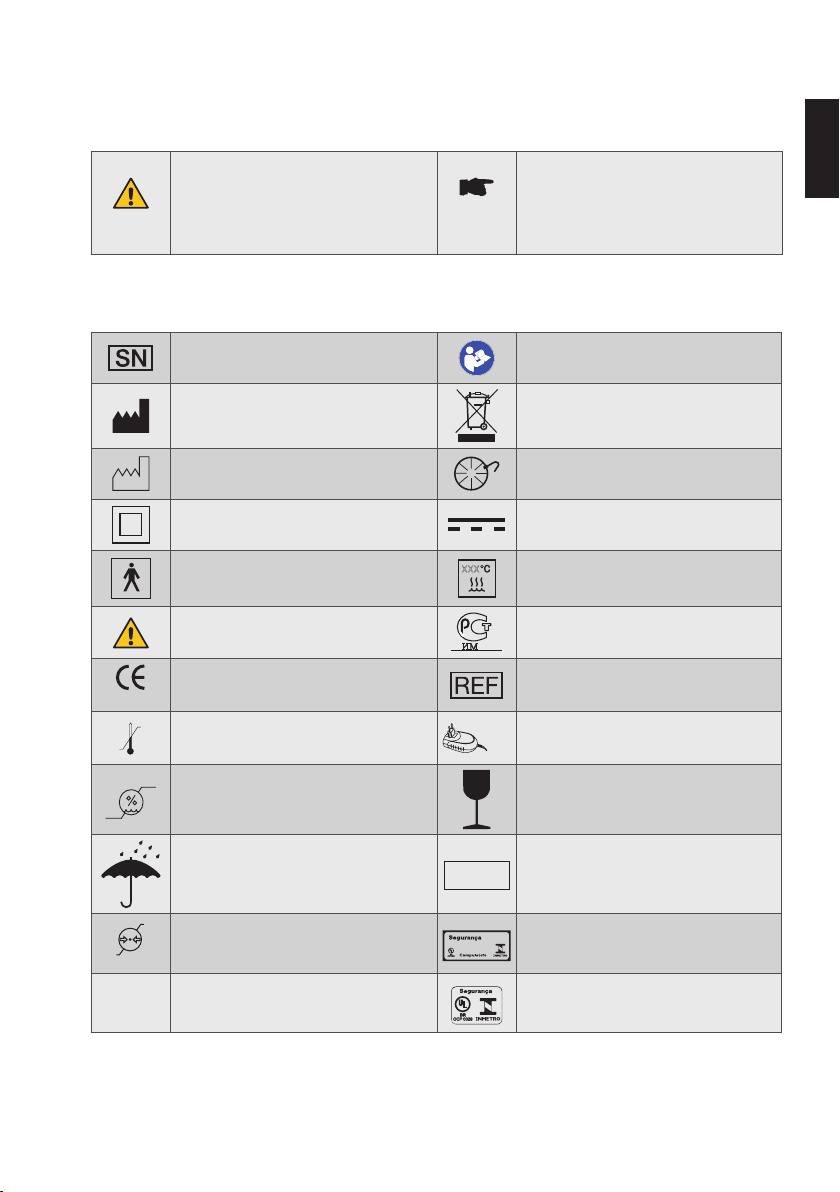
2.2. Auf Verpackung, Gerät und Komponenten verwendete Symbole
Seriennummer
Hersteller
Herstellungsdatum Anschluss Fußschalter
Produkt Klasse II
Anwendungsteil Typ BF
Warnhinweis
CE-Kennzeichnung und Referenznummer
der notifizierten Stelle
0123
+ 50° C
Temperaturbegrenzung
Siehe Gebrauchsanweisung (obligatorische
Maßnahme)
Nicht mit dem normalen Hausmüll
entsorgen
Gleichstrom
(Anschluss Ladegerät)
Dampfsterilisierbar bis zu der auf dem
Symbol angegeben Temperatur (XXX°C)
Gost-Symbol, das Produkt erfüllt russische
Sicherheitsstandards (GOST-R).
Katalognummer (Nachbestellnummer)
Das Gerät nur mit dem mitgelieferten
Ladegerät verwenden
de
Feuchtigkeitsgrenze Zerbrechlich!
IP-Schutzgrad gegen Staub und Wasser:
Trocken lagern!
IPN
Die beiden Zahlen (N1 und N2) geben
1N2
den Schutzgrad gegen Festkörper bzw.
Flüssigkeiten an
106 kPa
50 kPa
Luftdruckgrenze
®
INMETRO-Symbol auf Verpackung,
das Produkt erfüllt brasilianische
Sicherheitsstandards
INMETRO-Symbol auf dem Gerät,
®
das Produkt erfüllt brasilianische
Sicherheitsstandards
Page 6
6
3. Verwendungszweck, vorgesehener Anwender und Patientenpopulation
de
NUR FÜR DEN ZAHNÄRZTLICHEN
GEBRAUCH!
Der VDW.SILVER®RECIPROC® ist ein medizinisches Gerät
entsprechend der Richtlinie 93/42/EWG über Medizinprodukte, modifiziert durch die Richtlinie 2007/47/EG. Der
Endomotor wird für die zahnmedizinische Wurzelkanalbehandlung mit endodontischen Instrumenten in kontinuierlicher Rotation und alternierender Bewegung mit
Drehmomentkontrolle verwendet.
Dieses Gerät darf nur von qualifizierten Personen (Zahnärzten und Endodontologen) in Krankenhäusern, Zahnarztpraxen und Zahnkliniken verwendet werden.
Verwenden Sie das Gerät nicht für Implantate oder
andere zahnmedizinische Eingriffe, die nicht in den
Bereich der Endodontie fallen.
Alle Patienten können ohne Einschränkung in Bezug
auf Geschlecht, Abstammung und Alter mit dem
VDW.SILVER
nahme von Kindern.
®
RECIPROC® behandelt werden, mit Aus-
4. Kontraindikationen
Die Verwendung des VDW.SILVER®RECIPROC® ist kontraindiziert, wenn der Patient/Anwender aktive medizinische
Implantate trägt (Schrittmacher, Cochlea-Implantate …).
Sicherheit und Wirksamkeit wurden bei Schwangeren,
stillenden Frauen und Kindern nicht nachgewiesen.
Die klinische Beurteilung obliegt dem Endnutzer des
Gerätes.
5. Warnhinweise
Lesen Sie vor der Verwendung die folgenden Warnhinweise.
WARNHINWEISE
• Verwenden Sie dieses Gerät NICHT in Gegenwart von brennbaren Anästhetika oder oxidierenden Gasen (wie Stickstoffoxid N2O und
Sauerstoff) oder in der Nähe von flüchtigen
Lösungsmitteln (wie Ether oder Alkohol), da es
zu einer Explosion kommen kann.
• Modifikationen an diesem Medizinprodukt sind
nicht erlaubt. Wenn eine der Komponenten
ausgetauscht werden muss, wenden Sie sich
an das Servicezentrum.
• Verbinden Sie den VDW.SILVER
nicht mit anderen Geräten oder Systemen.
Schließen Sie kein Gerät über den USBAnschluss an den VDW.SILVER® RECIPROC®
an. Dieser USB-Anschluss ist ausschließlich
für die Nutzung durch autorisiertes Personal zu
Wartungszwecken oder für Software-Updates
vorgesehen.
• Die Komponenten des VDW.SILVER
RECIPROC® werden nicht desinfiziert oder sterilisiert geliefert: Komponenten wie die Steuereinheit, der Mikromotor und das Mikromotorkabel müssen vor der ersten Verwendung
desinfiziert und nach jeder weiteren Verwen
dung entsprechend wiederaufbereitet werden.
Das VDW6:1 Winkelstück muss vor der ersten
Verwendung desinfiziert und nach jeder wei
teren Verwendung entsprechend wiederaufbereitet werden.
• Verwenden Sie nur das mitgelieferte Ladege
rät.
• Das Ladegerät muss jederzeit zugänglich sein,
um es sofort von der Steckdose trennen zu
können.
• Verwenden Sie nur das VDW 6:1 Winkelstück
mit dem Gerät. Die Präzision des Drehmoments
und der Drehzahl ist nur gewährleistet, wenn
das VDW6:1 Winkelstück verwendet wird.
• Sollte Flüssigkeit aus dem VDW.SILVER
RECIPROC® austreten, die auf einen auslaufenden Akku zurückzuführen sein könnte, stellen Sie die Verwendung des Gerätes sofort ein
und trennen Sie es von der Steckdose. Wenden
Sie sich an das Servicezentrum.
• Sollten bei der Verwendung des Gerätes Stö
rungen auftreten, schalten Sie den Mikromotor
aus, trennen Sie das Gerät von der Steckdose
und wenden Sie sich an das Servicezentrum.
• Beachten Sie bei der Verwendung von endo
dontischen Instrumenten die Anweisungen in
der Anleitung des Feilenherstellers und in der
Bedienungsanleitung des VDW 6:1 Winkelstücks.
• Die Verwendung einer rotierenden Feile im
alternierenden Modus kann zu deren Bruch
führen. Verwenden Sie niemals rotierende
Feilen im alternierenden Modus. Überprüfen
Sie vor der Verwendung den auf dem Display
angezeigten Modus.
®
RECIPROC®
®
®
-
-
-
-
-
Page 7

7
• Die Verwendung einer reziprok rotierenden
Feile im Rotationsmodus kann zu deren Bruch
führen. Verwenden Sie niemals reziprok rotierende Feilen im Rotationsmodus. Überprüfen
Sie vor der Verwendung den auf dem Display
angezeigten Modus.
• Die zulässigen Drehmoment- und Drehzahl
werte können vom Feilenhersteller ohne vorherige Ankündigung geändert werden. Deshalb müssen die voreingestellten Werte vor der
Verwendung in der Bibliothek überprüft werden. Die auf dem Display angezeigten Werte
sind nur in Verbindung mit einem ordnungsgemäß gewarteten und geschmierten VDW 6:1
Winkelstück präzise und zuverlässig.
• Setzen Sie während der Kalibrierung keine
Feile ein. Verletzungsgefahr, da der Mikromo
tor während der Kalibrierung die Drehzahl vom
minimalen auf den maximalen Wert ändert.
Kalibrieren Sie das VDW 6:1 Winkelstück
immer vor Gebrauch und ohne Feilen.
• Stecken Sie nichts in den Mikromotor. Schmie
ren Sie den Mikromotor nicht, da er durch die
Schmierung beschädigt und seine Funktion
beeinträchtigt werden kann.
• Handschuhe und Kofferdam sind während
der Behandlung mit dem VDW.SILVER
RECIPROC® unverzichtbar.
-
-
-
®
WARNHINWEISE
• Verwenden Sie dieses Gerät NICHT in Gegenwart von brennbaren Anästhetika oder oxidierenden Gasen (wie Stickstoffoxid N2O und
Sauerstoff) oder in der Nähe von flüchtigen
Lösungsmitteln (wie Ether oder Alkohol), da es
zu einer Explosion kommen kann.
• Die folgenden Vorsichtsmaßnahmen sind zu
treffen, um allgemeine Gerätefehlfunktionen
bei elektromagnetischen Störungen zu ver
meiden:
- Die Verwendung anderer als der als Zube-
hör gelieferten oder aufgeführten Teile
kann die EMV-Eigenschaften negativ
beeinflussen.
- Beachten Sie stets die im Kapitel „Elektro-
magnetische Verträglichkeit“ aufgeführten
Informationen.
- Im Falle einer Gerätefehlfunktion, die ver-
mutlich durch elektromagnetische Störungen verursacht wird, überprüfen Sie zuerst
die Verkabelung und bewegen Sie dann
alle tragbaren HF-Kommunikationsgeräte
und mobilen Geräte, die sich in der Nähe
befinden, so weit wie möglich weg, um
Störungen auszuschließen.
- Wenn die elektromagnetischen Störungen
fortbestehen, stellen Sie die Verwendung
des Gerätes ein und bitten Sie das Servicezentrum um Unterstützung.
de
-
6. Vorsichtsmaßnahmen
Lesen Sie vor der Verwendung die folgenden Vorsichtsmaßnahmen.
Der Hersteller lehnt jede Verantwortung ab, wenn der
VDW.SILVER
Gebrauchsanweisung aufgeführten Anwendungen verwendet wurde.
®
RECIPROC® für andere als die in dieser
7. Unerwünschte Wirkungen
Es sind keine unerwünschten Wirkungen bekannt.
8. Einrichtung Schritt für Schritt
Dieses Kapitel enthält alle wichtigen Information zu Installation und Betrieb des VDW.SILVER®RECIPROC®.
Page 8
8
8.1. Gelieferte Komponenten und Zubehör
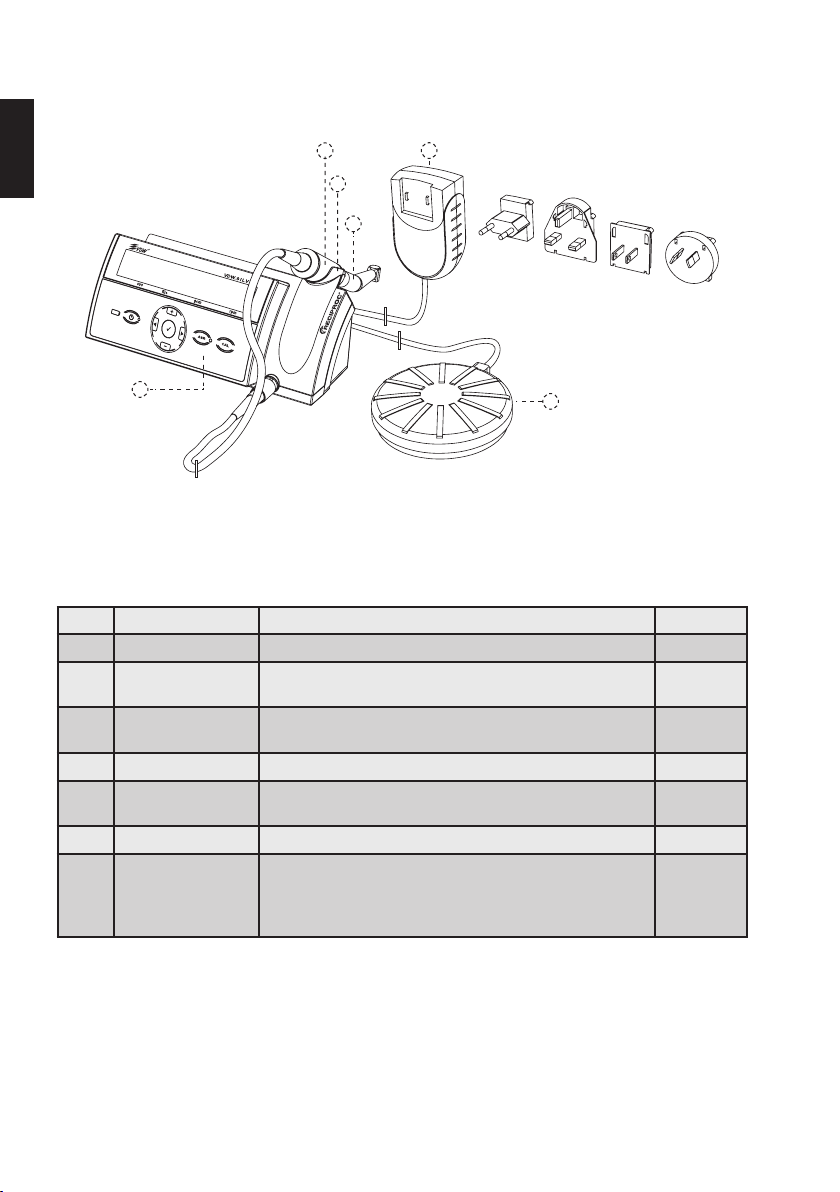
Der VDW.SILVER®RECIPROC® wird mit den unten aufgeführten Komponenten geliefert:
de
(
,
)
+
'
Abb. 1 VDW.SILVER®RECIPROC
®
*
Teil# REF Beschreibung
1) V04 1163 000 000 VDW.SILVER®RECIPROC® Gerät 1
2) - Mikromotor mit Kabel und Stecker
(Kabellänge: 1,8 m)
3) V041 079 000 000 VDW6:1 Winkelstück (separat verpackt mit zugehöriger Bedienungsanleitung)
4) V041 107 000 510 Fußschalter (Kabellänge 1,8m) 1
5) V041 107 000 517 Ladegerät (mit Ferritring) mit auswechselbaren Steckeradaptern
für EU, UK, USA, AUS (Kabellänge 1,8m)
6) - Handstückauflage 1
®
VDW.SILVER
RECIPROC® Benutzerhandbuch
Das Benutzerhandbuch kann heruntergeladen werden unter
https://www.vdw-dental.com/en/service/information-material/
directions-for-use/
Menge
1
1
1
1
Page 9
9
8.2. Erste Schritte
8.2.1. Vorbereitung
1) Nehmen Sie die Steuereinheit und die Zubehörteile
vorsichtig aus der Verpackung und legen Sie sie am
gewünschten Aufstellungsort auf eine ebene Fläche.
Beachten Sie bei der Wahl des Aufstellungsortes die in
Kapitel „14. Technische Daten“ aufgeführten Umgebungsspezifikationen.
WARNHINWEIS
Das Gerät erfordert spezielle Vorsichtsmaßnahmen im Hinblick auf elektromagnetische
Verträglichkeit (EMV) und muss unter strikter
Einhaltung der in dieser Gebrauchsanweisung enthaltenen EMV-Informationen aufgestellt und betrieben werden. Es ist besonders wichtig, das Gerät nicht in der Nähe
von Leuchtstofflampen, Funksendern oder
Fernbedienungen, tragbaren oder mobilen
Hochfrequenz-Kommunikationsgeräten zu
verwenden.
2) Überprüfen Sie das Gerät beim Öffnen der Verpackung und vor der Installation auf mögliche Schäden
und auf fehlende Teile. Informieren Sie den Lieferanten
innerhalb von 24 Stunden nach Erhalt des Gerätes über
fehlende Teile oder Transportschäden.
3) Überprüfen Sie, ob die Geräteseriennummer auf
der Unterseite der Steuereinheit mit den Angaben auf
der Verpackung und den Versanddokumenten übereinstimmt.
4) Überprüfen Sie, ob die Seriennummer des VDW6:1
Winkelstücks mit der auf dem Umkarton angegebenen
übereinstimmt.
5) Reinigen, desinfizieren und sterilisieren Sie das
VDW 6:1 Winkelstück (konsultieren Sie die separate
Bedienungsanleitung).
6) Reinigen und desinfizieren Sie die Vorderseite der
Steuereinheit, den Mikromotor und das Mikromotorkabel. Siehe Kapitel „9 Reinigung, Desinfektion und Sterilisation“.
WARNHINWEIS
Sollte Flüssigkeit aus dem Gerät austreten,
stellen Sie die Verwendung sofort ein und
trennen Sie das Ladegerät von der Steckdose.
Wenden Sie sich an das Servicezentrum.
7) Stellen Sie das Gerät nicht an einem feuchten Ort
auf, oder an einer Stelle, an der es kontinuierlich mit
Flüssigkeiten in Kontakt kommt.
8.2.2. Übersicht der Anschlüsse
Quetschen Sie die Kabel von Mikromotor, Fußschalter
und Ladegerät nicht und ziehen Sie beim Ein- und Ausstecken von Komponenten nicht direkt an den Kabeln.
Stellen Sie sicher, dass Kabel kein Hindernis darstellen
und die Mobilität nicht einschränken.
de
WARNHINWEIS
Die gelieferten Komponenten sind weder
sterilisiert noch desinfiziert. Befolgen Sie
vor dem Betrieb des Gerätes die im Kapitel
„9. Reinigung, Desinfektion und Sterilisation“
angegebenen Informationen.
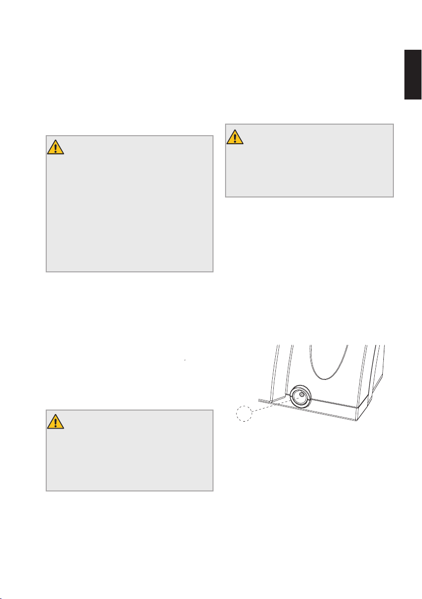
A
Abb. 2 Vorderer Anschluss
Vorderansicht
A) Anschlussbuchse für den Mikromotor.
Page 10
de
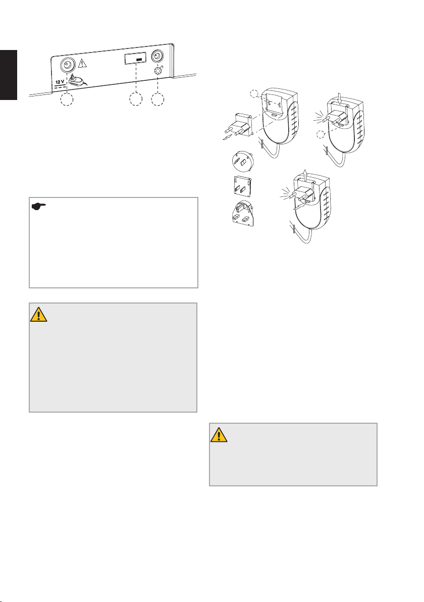
Abb. 3 Hintere Anschlüsse
10
8.2.3. Ladegerät
1) Wählen Sie den für Ihre Steckdose geeigneten Ste-
Model:
TR30RAM120
B
DC
ckeradapter (siehe Abb. 4).
E
Rückansicht
B) Anschlussbuchse für das Ladegerät.
C) Anschlussbuchse für den Fußschalter.
D) USB-Anschluss für Updates (nur für Servicepersonal).
HINWEIS
Über den USB-Anschluss (Abb. 3, D) können
Software-Updates installiert bzw. Wartungen
durchgeführt werden. Dieser Anschluss darf
nur von autorisiertem Servicepersonal verwendet werden und ist durch einen USB-Stecker abgedeckt, der nur vom Servicepersonal
entfernt werden darf.
WARNHINWEIS
Verbinden Sie den VDW.SILVER
®
RECIPROC®
nicht mit anderen Geräten oder Systemen.
Schließen Sie kein Gerät über den USBAnschluss an den VDW.SILVER®RECIPROC®
an. Dieser USB-Anschluss ist ausschließlich
für die Nutzung durch autorisiertes Personal
zu Wartungszwecken oder für SoftwareUpdates vorgesehen.
F
Abb. 4 Ladegerät und Steckeradapter
2) Setzen Sie den geeigneten Steckeradapter auf die
beiden Kontakte (Abb. 4, E) am Ladegerät und drücken
Sie ihn in Richtung Verriegelungstaste, bis er einrastet.
Zum Auswechseln des Adapters müssen Sie die Verriegelungstaste drücken.
3) Stecken Sie das Kabel des Ladegeräts in die
Anschlussbuchse (Abb. 3, B) an der Rückseite des Gerätes.
4) Stecken Sie das Ladegerät in die Steckdose ein und
achten Sie dabei darauf, dass es jederzeit zugänglich ist,
um sofort von der Steckdose getrennt werden zu können.
Der Akku wird geladen.
5) Laden Sie den Akku vor der ersten Verwendung
vollständig auf. Siehe Kapitel 8.2.5für Informationen zur
richtigen Akkupflege.
WARNHINWEIS
Das Ladegerät muss jederzeit zugänglich
sein, um es sofort von der Steckdose trennen
zu können.
Page 11
11
8.2.4. Mikromotor, VDW6:1 Winkelstück und
Fußschalter
6) Schließen Sie den Stecker des Mikromotorkabels an
die Anschlussbuchse (Abb. 2, A) auf der Vorderseite der
Steuereinheit an.
HINWEIS
Die Anschlussbuchse (Abb. 2, A) ist ein normaler Einsteckanschluss. Richten Sie den
roten Punkt auf dem Stecker senkrecht aus,
so dass er in die Führung der Buchse passt.
Den Stecker nicht in die Buchse einschrauben. Um die Verbindung zu trennen, ziehen
Sie am Metallende des Kabels. Verdrehen Sie
den Stecker beim Herausziehen nicht.
7) Entfernen Sie den schwarzen Sprühaufsatz vom
VDW6:1 Winkelstück.
8) Stecken Sie das VDW6:1 Winkelstück in den Mikromotor (siehe auch separate Bedienungsanleitung für das
VDW6:1 Winkelstück).
9) Stecken Sie das Fußschalterkabel in die Anschlussbuchse (Abb. 3, C) auf der Rückseite der Steuereinheit.
8.2.5. Akku
Der VDW.SILVER® RECIPROC® läuft mit einem NickelMetallhydrid-Akku (NiMH). Dieses Kapitel enthält Informationen für den richtigen Umgang mit dem Akku.
HINWEIS
Laden Sie den Akku vor der ersten Verwendung vollständig auf.
LED-Akkuanzeige
Die LED-Akkuanzeige zeigt den aktuellen Akkuzustand mit drei verschiedenen Farben an:
Grün: Zeigt eine Akkukapazität von 20-100 % an.
Rot blinkend: Der Akku muss aufgeladen werden. Die
Akkuleistung ist in ein paar Minuten erschöpft.
Wenn die Akku-LED während dem Betrieb beginnt, rot zu
blinken, schließen sie das Gerät sofort an das Ladegerät
an, da sich das Gerät andernfalls während der Behandlung abschaltet.
Die Akkuwarnung ist ein Alarmsignal mit HOHER Priorität.
Bevor sich der Motor abschaltet, ertönt 22 Sekunden lang
ein Warnalarm mit zwei unterschiedlichen Frequenzen
und es erscheint folgende Meldung:
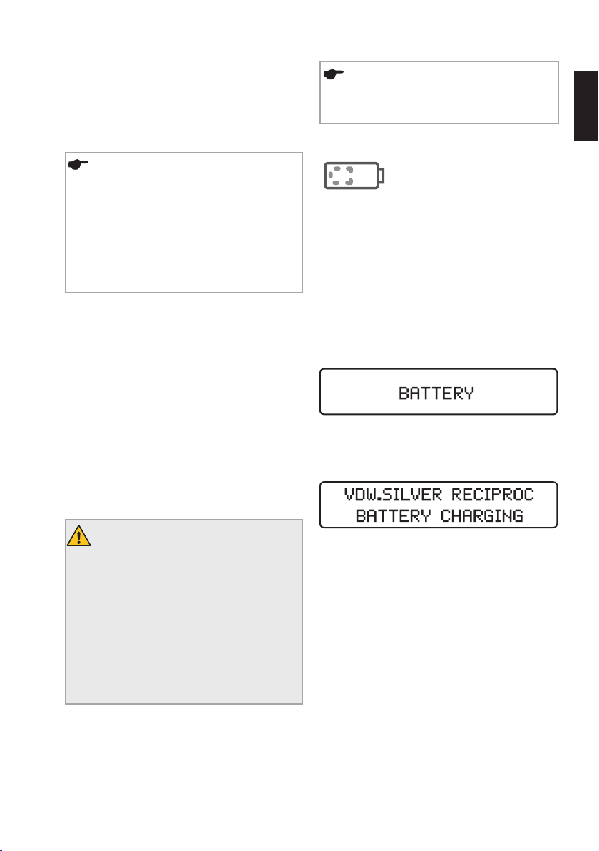
Orange blinkend: Das Ladegerät ist richtig angeschlossen und der Akku wird geladen. Auf dem Display
erscheint folgende Anzeige:
de
WARNHINWEISE
• Öffnen Sie das Gerät in keinem Fall. Keine
wartbaren Teile im Inneren. Wenn die Batterie
ausgetauscht werden muss, wenden Sie sich
an das Servicezentrum.
• Sollte Flüssigkeit aus dem VDW.SILVER
RECIPROC® austreten, die auf einen auslaufenden Akku zurückzuführen sein könnte, stellen Sie die Verwendung des Gerätes sofort ein
und trennen Sie es von der Steckdose. Wenden
Sie sich an das Servicezentrum.
Der VDW.SILVER® RECIPROC® kann während des Ladevorgangs normal und ohne erhebliche Verlängerung der
Ladezeit verwendet werden. Das Ladegerät ist stark
genug, um den Mikromotor direkt mit Strom zu versorgen.
®
Wenn der Akku vollständig aufgeladen ist, leuchtet die
Akku-LED-Leuchte wieder grün.
Page 12
12
Betriebs- und Ladezeiten
Bei vollständiger Entladung kann der Ladevorgang des
Akkus bis zu 3 Stunden dauern.
de
Bei richtiger Ladung hat der Akku in der Regel eine
Betriebszeit von etwa 2 Stunden, bevor er erneut aufgeladen werden muss.
Verlängerung der Akku-Lebensdauer
Für eine lange Lebensdauer des Akkus wird empfohlen,
stets mit Akkustrom zu arbeiten und den Akku erst wieder aufzuladen, wenn er vollständig entladen ist.
8.3. Benutzeroberfläche
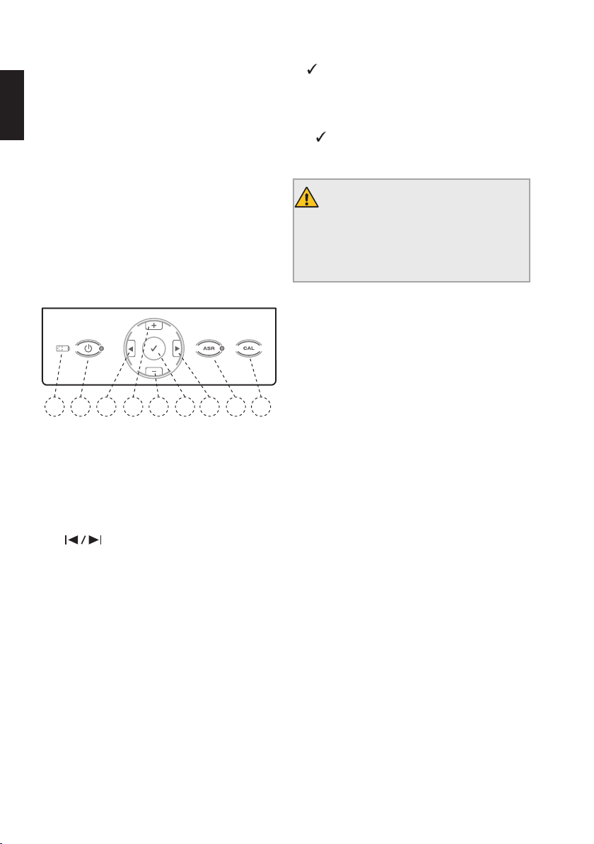
8.3.1. Tastenfeld
1
2
Abb. 5 Tastenfeld
1) EIN/AUS
Schaltet das Gerät ein und aus.
2) LED-Akkuanzeige
Zeigt den aktuellen Akku-Status an (siehe Einzelheiten
hierzu in Kapitel „8.2.5. Akku“).
3+4)
Scrollt rechts/links in der unteren Reihe des Displays
durch die Felder Feilensystem, Feile, Drehmoment und
Drehzahl. Das aktive Feld wird durch einen Pfeil angezeigt (nur im Rotationsmodus verfügbar).
5+6) +/–
Die Tasten + und - ermöglichen, durch die Feilensysteme
und Feilen zu scrollen und die Drehmoment- oder Drehzahlwerte in allen rotierenden Feilensystemen individuell
zu ändern.
3
6
5
4
7
7)
Bestätigen
Bestätigt Modifikationen der Drehmoment- und Drehzahleinstellungen in jedem System, in dem Modifikationen
möglich sind. Lädt außerdem wieder die Standardparameter, wenn zusammen mit der Taste EIN/AUS verwendet.
Mit der Taste CONFIRM (Bestätigen) kann der
Mikromotor auch ohne den Fußschalter gestartet werden.
8) CAL
WARNHINWEIS
Setzen Sie während der Kalibrierung keine
Feile ein. Verletzungsgefahr, da der Mikromotor während der Kalibrierung die Drehzahl vom
minimalen auf den maximalen Wert ändert.
Kalibriert das VDW 6:1 Winkelstück, um die Drehmomentgenauigkeit nach einem Austausch oder nach der
Schmierung sicherzustellen (siehe Einzelheiten in Kapitel
„8.4.2. CAL: Kalibrierung“).
9) ASR – Nur im Rotationsmodus
LED grün: Im Rotationsmodus stoppt die Umkehrung
der Drehrichtung automatisch, wenn das voreingestellte
Drehmoment erreicht ist.
8
9
LED rot: Im Rotationsmodus Umkehrung der Rotationsrichtung ohne Drehmomentgrenzen, mit dem Fußschalter gesteuert.
LED aus: Im Rotationsmodus stoppt der Mikromotor,
wenn das voreingestellte Drehmoment erreicht ist.
ASR ist im alternierenden Modus deaktiviert (LED aus).
Page 13

13
8.3.2. Display
Beim Einschalten des Gerätes leuchten alle LEDs auf und
ein Begrüßungstext wird angezeigt. Bei den folgenden
Verwendungen wird das zuletzt verwendete Feilensystem angezeigt.
Wenn das Gerät aus dem Standby-Modus aktiviert wird
(durch Drücken des Fußschalters oder einer Taste auf
dem Tastenfeld), wird auf dem Display das vor dem
Standby-Modus zuletzt verwendete Feilensystem angezeigt.
Obere Zeile:
Zeigt, welcher Modus gewählt ist – entweder rotierender
oder alternierender Modus, dargestellt mit ROTARY oder
RECIPROCATION.
Untere Zeile im Rotationsmodus:
Zeigt die Felder Feilensystem (sys), Feile (file), Drehmoment (gcm) und Drehzahl (rpm) an:
sys file gcm rpm
sys
Zeigt das ausgewählte rotierende Feilensystem an
(z. B. MTWO für Mtwo
Dr’sChoice usw.)
file
Zeigt die ausgewählte Feile an.
gcm
Zeigt den voreingestellten Drehmomentgrenzwert an
(im alternierenden Modus deaktiviert). Das Drehmoment
wird in g/cm angegeben (Gramm Kraft pro Zentimeter:
1gcm = 0,0981 Nmm).
rpm
Zeigt die Feilendrehzahl in Upm (Umdrehungen pro
Minute) an (im alternierenden Modus deaktiviert).
Wenn die Standardeinstellungen für die Drehzahl geändert werden, wird ein ‘ vor dem neuen Wert angezeigt.
®
, FM für FlexMaster®, DR’s für
• Drücken Sie die Tasten
und links zu gelangen (nur im Rotationsmodus).
• Drücken Sie die Tasten + und -, um durch die Feilensysteme und Feilen zu scrollen und die Drehmomentoder Drehzahlwerte in allen rotierenden Feilensystemen individuell zu ändern.
• Die Motoreinstellungen können für alternierende Systeme nicht geändert werden.
• Wenn Drehmoment- oder Drehzahlwerte abweichend
von den Standardeinstellungen geändert werden, zeigt
das Display ein ‘-Symbol vor dem Drehmoment- oder
Drehzahlwert.
Untere Zeile im alternierenden Modus:
Zeigt das verwendete reziprok rotierende System an.
Im Gegensatz zum Rotationsmodus können im alternierenden Modus keine einzelnen Feilen ausgewählt werden, da alle Motoreinstellungen für das gesamte System
gelten (angezeigt durch RECIPROC ALL).
und , um nach rechts
8.3.3. Fußschalter
HINWEISE
• Um eine lange Lebensdauer zu gewährleisten,
knicken Sie die Kabel nicht.
• Falls das Fußpedal zum Verrutschen neigt, rei
nigen Sie die Gummifüße.
Der Mikromotor kann auf zwei verschiedene Arten
gestartet werden:
• Der Fußschalter wird gedrückt und der Mikromotor
arbeitet, so lange der Fußschalter gedrückt bleibt;
• Der Mikromotor wird durch 1,5 Sekunden langes Drücken der Taste CONFIRM (Bestätigen)
Der Mikromotor kann durch Drücken einer beliebigen
Taste oder durch Betätigen des Fußschalters wieder
gestoppt werden. Wenn der Mikromotor mit der Taste
CONFIRM (Bestätigen) gestartet wird, schaltet er
nach 5 Minuten Inaktivität automatisch ab, um Akkuladung zu sparen.
-
gestartet.
de
Page 14
14
8.3.4. Akustische Signale
Alle akustischen Signale sind bei Lieferung des Gerätes aktiviert:
de
Komponenten Akustisches Signal
Tastenfeld
Tasten Bestätigungston beim Drücken der Tasten auf dem Tastenfeld.
Motor
Akustisches Signal wenn das Drehmoment im Rotationsmodus ungefähr
Rotationsmodus
75 % des voreingestellten Wertes überschreitet.
Intermittierendes Signal bei kontinuierlicher Rotation gegen den
Uhrzeigersinn.
Alternierender Modus
Akustisches Signal wenn die gesamte Länge des Instruments unter
erhöhter Belastung steht. Siehe Kapitel „8.5.4. Alternierender Modus“.
Akku
Akkustatus
Lautes Warnsignal bei leerem Akku, bevor sich das Gerät ausschaltet. Die
Akkuwarnung ist ein Alarmsignal mit HOHER Priorität.
Deaktivieren und Aktivieren der akustischen Signale
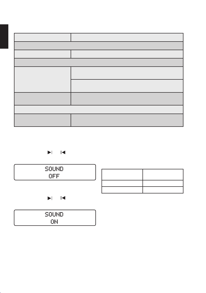
Um die akustischen Signale zu deaktivieren, drücken Sie
gleichzeitig die Tasten
und : Ein Piepton erklingt
und die folgende Nachricht wird angezeigt:
Um die akustischen Signale zu aktivieren, drücken Sie
gleichzeitig die Tasten und : Ein Piepton erklingt
und die folgende Nachricht wird angezeigt:
8.3.5. Feilenbibliothek
Das Gerät enthält eine Feilenbibliothek mit folgenden
voreingestellten Systemen:
Feilensysteme mit alternierender Rotation:
Name des Feilensystems Am Gerät angezeigter
®
RECIPROC
WaveOne™ WAVEONE ALL
Alle Motoreinstellungen gelten für das gesamte System,
angezeigt durch RECIPROC ALL und WAVEONE ALL.
Name
RECIPROC ALL
Page 15
15
Rotierende Systeme:
Name des Feilensystems Am Gerät angezeigter
VDW.ROTATE VROT
®
Mtwo
FlexMaster
Gates Glidden GATE
Benutzerdefiniertes
Programm Dr’sChoice
TruNatomy™ TN
ProFile
ProGlider
ProTaper
ProTaper
K3™ K3
FlexMaster
FlexMaster
Lentulo LENT
®
®
®
®
Universal PTU
®
Next PTN
®
Retreatment1 RE1
®
Retreatment2 RE2
Name
MTWO
FM
DR’S
PF
PG
Vergewissern Sie sich vor dem Starten des Mikromotors,
dass das auf dem Display angezeigte Feilensystem mit
der verwendeten Feile übereinstimmt. Siehe Gebrauchsanweisung der verwendeten Feile bezüglich der richtigen
Einstellungen.
Die am Gerät angezeigten Werte sind nur mit einem ordnungsgemäß gewarteten VDW 6:1 Winkelstück präzise
und zuverlässig.
WARNHINWEIS
Beachten Sie bei der Verwendung von endodontischen Instrumenten die Anweisungen
in der Anleitung des Herstellers und in der
Bedienungsanleitung des VDW 6:1 Winkelstücks.
8.4. Betrieb
8.4.1. Einschalten, Standby-Modus,
Ausschalten
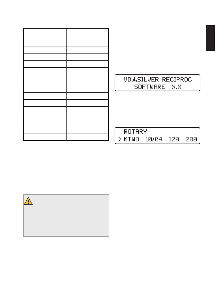
Einschalten
Drücken Sie die EIN/AUS-Taste. Alle LEDs werden auf
Funktionsfähigkeit überprüft und leuchten dabei kurz
auf. Ein Begrüßungsbildschirm zeigt die aktuelle Softwareversion an:
Bei nachfolgenden Sitzungen wird auf dem Display die
erste Feile des zuletzt verwendeten Systems, bevor das
Gerät ausgeschaltet wurde, oder die letzte verwendete
Feile, bevor der Standby-Modus aktiviert wurde, angezeigt.
Standby-Modus
Wenn das Gerät 10 Minuten nicht verwendet wird, schaltet es automatisch in den Standby-Modus, um Akkuladung zu sparen. Das Display schaltet sich ab.
Um den Standby-Modus zu verlassen, drücken Sie eine
beliebige Taste auf dem Tastenfeld oder betätigen Sie
den Fußschalter. Das Gerät schaltet sich ein und kehrt
in die vor dem Wechsel in den Standby-Modus zuletzt
verwendete Funktion zurück.
Nach 30 Minuten im Standby-Modus schaltet sich das
Gerät vollständig ab, um Akkuladung zu sparen.
Es kann durch Drücken der EIN/AUS-Taste wieder eingeschaltet werden.
Ausschalten
Drücken Sie die EIN/AUS-Taste, um das Gerät auszuschalten. Die Akku-LED-Leuchte erlischt, es sei denn,
der Akku wird geladen.
de
Page 16
16
8.4.2. CAL: Kalibrierung
de
WARNHINWEIS
Die Präzision der Arbeitsparameter ist nur
gewährleistet, wenn ein korrekt gewartetes
VDW6:1 Winkelstück verwendet wird.
Bei der Kalibrierung des Mikromotors wird die Drehzahl
automatisch eingestellt, um die Drehmomentgenauigkeit
sicherzustellen. Die Kalibrierung ist notwendig:
• Nach dem Austausch des Mikromotors;
• Nach dem Wechseln und der Aufbereitung des VDW6:1
Winkelstücks und mindestens ein Mal pro Woche
(siehe auch die separate Bedienungsanleitung für das
VDW6:1 Winkelstück).
Starten der Kalibrierung
1) Stecken Sie das VDW6:1 Winkelstück ohne Feile auf
den Mikromotor.
WARNHINWEIS
Setzen Sie während der Kalibrierung keine
Feile ein. Verletzungsgefahr, da der Mikromotor während der Kalibrierung die Drehzahl vom
minimalen auf den maximalen Wert ändert.
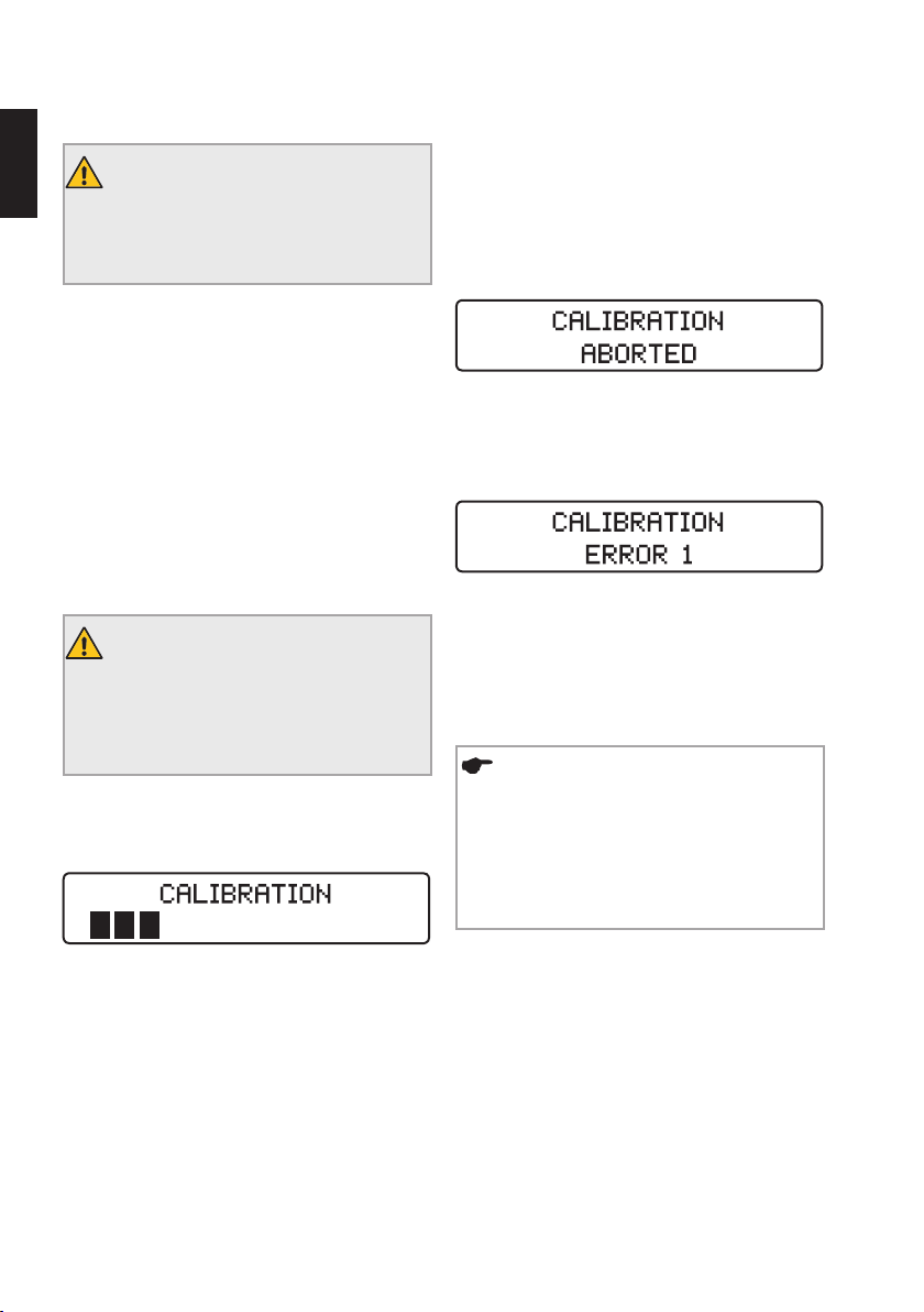
2) Drücken Sie die Taste CAL. Der Kalibrierungsvor-
gang wird gestartet und auf dem Display erscheint folgende Anzeige.
3) Der Vorgang stoppt von selbst, sobald die Kalibrierung abgeschlossen ist (auf dem Display sind alle
schwarzen Balken sichtbar).
Abbruch der Kalibrierung
Der Kalibriervorgang kann durch Drücken einer beliebigen Taste oder durch Betätigen des Fußschalters jederzeit abgebrochen werden. Die folgende Nachricht wird
angezeigt:
Mögliche Fehlermeldungen
Kann der Kalibrierungsvorgang nicht korrekt durchgeführt oder abgeschlossen werden, erscheint auf dem
Display folgende Nachricht:
Einzelheiten zu möglichen Fehlermeldungen wie ERROR
1 oder ERROR 2 finden Sie in Kapitel „10.2. Fehlerbehebung“.
8.4.3. ASR: Automatic Stop Reverse
HINWEIS
Die ASR-Funktion kann nur im Rotationsmodus aktiviert werden. Bei Lieferung ist die
ASR-Funktion für den Rotationsmodus aktiv
(LED grün).
ASR ist im alternierenden Modus deaktiviert
(LED aus).
Der Mikromotor beschleunigt von der minimalen Drehzahl bis auf die maximale Drehzahl, um automatisch die
Trägheit des Winkelstücks zu messen.
Im Rotationsmodus kann die ASR-Funktion durch Drücken der Taste ASR geändert werden. Die LED-Leuchte
ändert entsprechend der ausgewählten Funktion ihre
Farbe:
Grün: Der Mikromotor dreht sich bei Erreichen des voreingestellten Drehmoments automatisch in Gegenrichtung (gegen den Uhrzeigersinn). Sobald die Feile nicht
mehr auf Widerstand trifft, dreht der Mikromotor automatisch wieder in Vorwärtsrichtung (im Uhrzeigersinn).
Page 17
17
Rot: Der Mikromotor dreht automatisch rückwärts (gegen
den Uhrzeigersinn) ohne Drehmomentkontrolle.
AUS: Im Rotationsmodus stoppt der Mikromotor automatisch, wenn das voreingestellte Drehmoment erreicht
ist. Durch erneutes Drücken des Fußschalters dreht der
Mikromotor rückwärts (gegen den Uhrzeigersinn). Sobald
die Feile nicht mehr auf Widerstand trifft, dreht der Mikromotor automatisch wieder in Vorwärtsrichtung (im Uhrzeigersinn).
HINWEIS
Die ASR-Funktionen können für jede Feile im
Rotationsmodus eingestellt werden. Die Einstellung kehrt wieder zur Standardeinstellung
(LED grün) zurück, sobald Sie eine andere
Feile auswählen.
Akustische Signaltöne:
• Wenn das Drehmoment etwa 75 % des voreingestellten Werts überschreitet;
• Wenn der Mikromotor rückwärts dreht.
8.5. Auswahl Feilensysteme/Feilen
WARNHINWEIS
Überprüfen Sie vor der Verwendung stets den
auf dem Display angezeigten Modus:
- Die Verwendung einer rotierenden Feile im
alternierenden Modus kann zu deren Bruch
führen. Verwenden Sie niemals rotierende
Feilen im alternierenden Modus.
- Die Verwendung einer reziprok rotierenden
Feile im Rotationsmodus kann zu deren Bruch
führen. Verwenden Sie niemals reziprok rotierende Feilen im Rotationsmodus.
Im Display wird standardmäßig das zuletzt verwendete
Feilensystem bzw. die entsprechende zuletzt verwendete
Feile angezeigt. Um eine neue Auswahl zu treffen, gehen
Sie wie folgt vor:
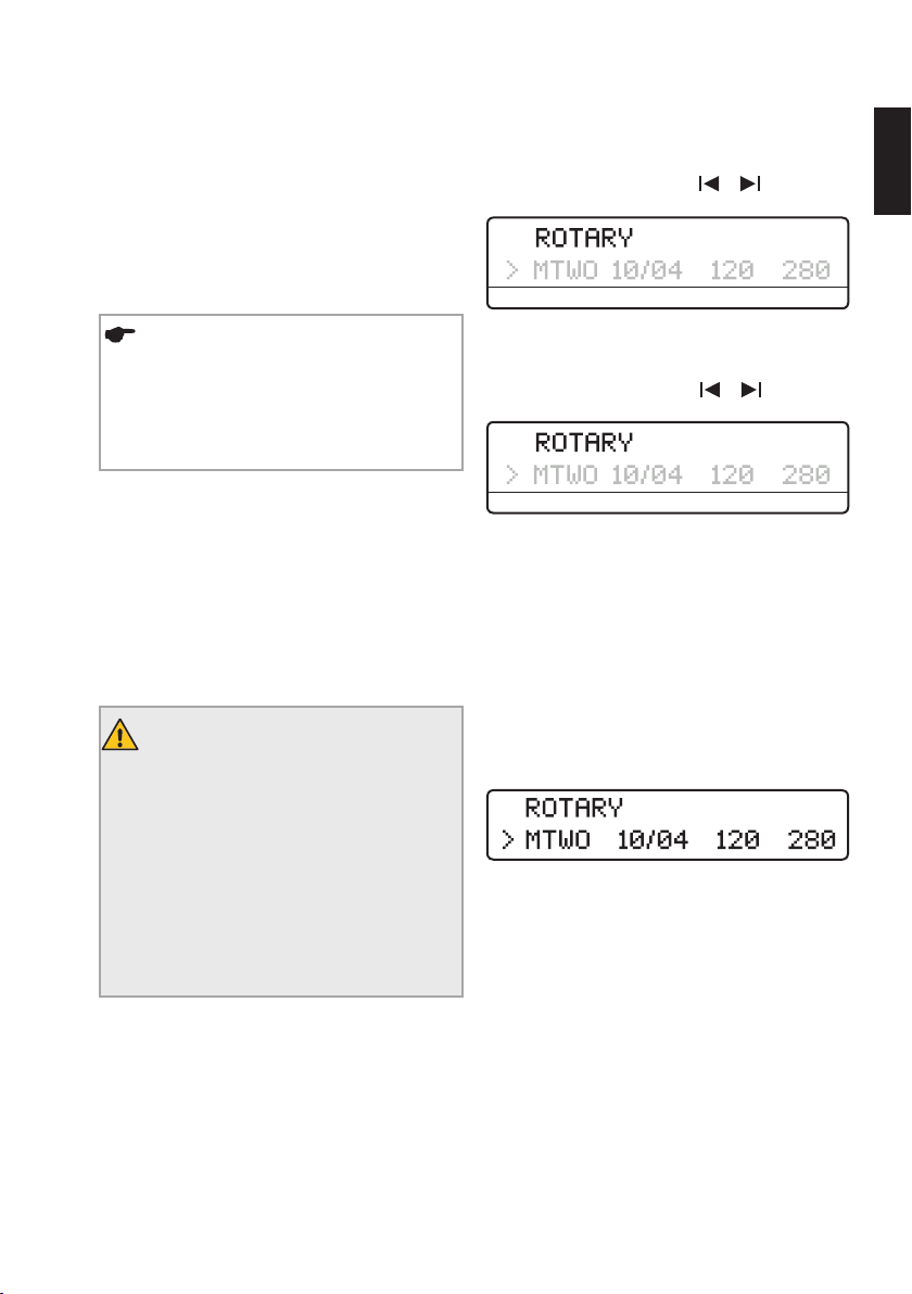
1) Wählen Sie mit den Tasten
aus (Pfeil):
/ das Feld sys
sys file gcm rpm
2) Wählen Sie mit den Tasten +/– das gewünschte Feilensystem aus (nach oben/unten blättern).
3) Wählen Sie mit den Tasten / das Feld file
aus (Pfeil):
sys file gcm rpm
4) Wählen Sie mit den Tasten +/– die gewünschte
Feile aus (nach oben/unten blättern).
5) Die Einstellung muss nicht bestätigt werden. Die
gewünschte Feile bzw. das gewünschte Feilensystem ist
nun aktiv.
8.5.1. Rotationsmodus
Wenn im Rotationsmodus ein Feilensystem gewählt
wurde, zeigt die erste Zeile im Display:
In der zweiten Zeile wird automatisch die erste Feile in
der Sequenz angezeigt.
Im Rotationsmodus können die Drehmoment- und Drehzahlwerte aller Feilensysteme individuell geändert werden. Gehen Sie dabei wie in Kapitel „8.5.2. Änderung von
Drehmoment und Drehzahl (nur im Rotationsmodus)“
beschrieben vor.
de
Page 18
18
HINWEISE
• Die ASR-Funktion kann nur im Rotations-
de
modus aktiviert werden. Bei Lieferung ist die
ASR-Funktion aktiv (LED grün). Wählen Sie
durch Drücken der Taste ASR verschiedene
Funktionen (siehe Einzelheiten hierzu in Kapitel
„8.4.3. ASR: Automatic Stop Reverse“)
• Wenn die rotierende Feile im Kanal feststeckt,
schalten Sie in die umgekehrte ASR-Funktion
(LED rot), starten Sie den Motor neu und ziehen
Sie die Feile vorsichtig heraus.
8.5.2. Änderung von Drehmoment und Drehzahl (nur im Rotationsmodus)
Die voreingestellten Drehmoment- und Drehzahlwerte
aller Feilensysteme können im Rotationsmodus individuell geändert werden.
WARNHINWEIS
Die Einstellung von Drehmoment und Drehzahl
über die empfohlenen Werte hinaus kann zu
Feilenbruch während der Behandlung führen.
Beachten Sie stets die Gebrauchsanweisung
der verwendeten Feile bezüglich der richtigen
Einstellungen.
Ändern des Drehmoments:
1) Wählen Sie wie oben beschrieben die gewünschte
rotierende Feile aus (Pfeil zeigt aktive Auswahl an).
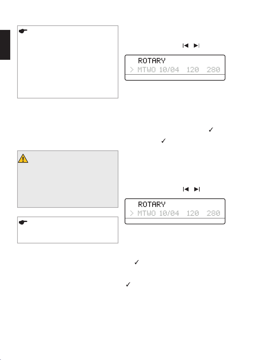
2) Wählen Sie mit den Tasten
aus (Pfeil):
/ das Feld gcm
sys file gcm rpm
3) Wählen Sie mit den Tasten +/– das gewünschte
Drehmoment aus (nach oben/unten blättern). Wenn der
Drehmomentwert geändert wird, blinkt das Feld. Es sind
Drehmomenteinstellungen von 20 bis 410gcm in Schritten von jeweils 10gcm möglich.
4) Speichern Sie nach der Auswahl des gewünschten
Drehmoments die neue Einstellung durch einmaliges
Drücken der Taste CONFIRM (Bestätigen) . Das
Drehmomentfeld hört auf zu blinken und wird mit einem
‘-Symbol markiert. Wird die Einstellung nicht durch
Drücken der Taste CONFIRM (Bestätigen) gespeichert,
kann sie nicht verwendet werden und der Mikromotor
startet nicht.
Ändern der Drehzahl:
1) Wählen Sie wie oben beschrieben die gewünschte
rotierende Feile aus (Pfeil zeigt aktive Auswahl an).
2) Wählen Sie mit den Tasten
aus (Pfeil):
/ das Feld rpm
HINWEIS
Drehmoment und Drehzahl können im alternierenden Modus nicht geändert werden.
sys file gcm rpm
3) Wählen Sie mit den Tasten +/– die gewünschte
Drehzahl aus (nach oben/unten blättern). Wenn der Drehzahlwert geändert wird, blinkt das Feld. Der verfügbaren
Drehzahlwerte bewegen sich im Bereich von 250 bis
1000Upm in Schritten von jeweils 10Upm.
4) Speichern Sie nach der Auswahl der gewünschten Drehzahl die neue Einstellung durch einmaliges Drücken der Taste CONFIRM (Bestätigen). Das Drehzahlfeld
hört auf zu blinken und wird mit dem ‘-Symbol markiert.
Wird die Einstellung nicht durch Drücken der Taste
CONFIRM (Bestätigen) gespeichert, kann sie nicht verwendet werden und der Mikromotor startet nicht.
Page 19
19
8.5.3. Dr’sChoice (nur im Rotationsmodus)
Sie haben die Möglichkeit, mit dem benutzerdefinierten
Programm Dr’sChoice Ihre eigene Feilensequenz zusammenzustellen. Somit können Sie Ihre eigene Instrumentenabfolge verwalten.
Das Gerät wird mit 15 standardmäßigen Drehmoment- und Drehzahlwerten ausgeliefert (siehe Kapitel
„15. Dr’sChoice Tabellen“ für Einzelheiten zu den Standardwerten).
Zum Ändern dieser Einstellungen genügt es, sie zu
„überschreiben“, wie in Kapitel „8.5.2. Änderung von
Drehmoment und Drehzahl (nur im Rotationsmodus)“
beschrieben. Verwenden Sie die Tabelle in Kapitel
„15. Dr’s Choice Tabellen“, um Ihre benutzerdefinierten Einstellungen zu notieren. Zur Wiederherstellung
der Standardeinstellungen folgen Sie dem in Kapitel
„8.6. Werkseinstellungen“ beschriebenen Verfahren.
8.5.4. Alternierender Modus
RECIPROC® und WaveOneTM Instrumente sind speziell für
die Verwendung im alternierenden Modus ausgelegt, in
dem das Instrument zunächst in eine Schneidrichtung
dreht und dann rückwärts dreht, um das Instrument
wieder freizugeben. Die Drehwinkel der reziproken
Bewegung sind präzise und speziell auf die Instrumente
ausgerichtet.
HINWEISE
• Die RECIPROC® und WaveOneTM reziprok rotierenden Feilen unterscheiden sich durch folgende Merkmale von rotierenden Feilen: Der
Schaft hat einen farbigen Kunststoffring und
die Schneidkanten sind umgekehrt.
• Die ASR-Funktion, die für den Rotationsmodus
ausgelegt ist, wird im alternierenden Modus
deaktiviert.
Arbeiten im alternierenden Modus
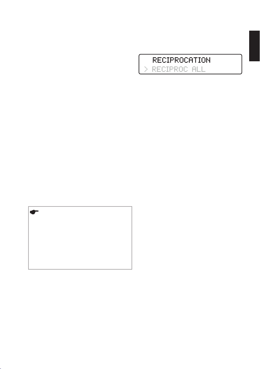
Wenn eine der oben genannten reziprok rotierenden Feilen ausgewählt wird, wird in der ersten Zeile auf dem
Display angezeigt:
Wählen Sie das spezielle alternierende System RECIPROC
oder WAVEONE durch Auswahl des „Systems“ in der
zweiten Zeile des Displays über die Tasten + und -. Im
Gegensatz zum Rotationsmodus können im alternierenden Modus keine einzelnen Feilen ausgewählt werden,
da alle Motoreinstellungen für das gesamte System gelten, angezeigt durch RECIPROC ALL.
RECIPROC-REVERSE-Funktion
(für VDWRECIPROC
Diese Funktion erleichtert das Arbeiten und macht durch
akustische Signale auf den nachfolgenden Ablauf bzw.
notwendige Maßnahmen aufmerksam:
• Ein tiefer, schnell piepender Ton weist auf eine
erhöhte Belastung über die gesamte Länge des Instruments hin. Es ist also notwendig, den Kanal mit lateralen Bürstbewegungen zu erweitern. Dadurch wird die
Belastung des Instruments reduziert.
• Ein höherer, langsam piepender Ton weist auf eine
noch höhere Belastung des Instruments hin. Der
Mikromotor schaltet automatisch in den rotierenden
Rechtslauf, um das Instrument zu entlasten. Sobald
der Fußschalter freigegeben und dann erneut gedrückt
wird, wechselt der Mikromotor wieder in den alternierenden Modus. Nun ist es wichtig, eine lateral bürstende Bewegung auszuführen, um den Wurzelkanal zu
erweitern.
®
Instrumente)
de
Page 20

20
HINWEISE
Bürsten Sie in gekrümmten Kanälen weg von
de
der Kanalkrümmung. Wiederholen Sie vor
dem Bürsten folgende Schritte:
• Reinigen Sie das Instrument im Zwischenhalter;
• Spülen Sie den Kanal;
• Prüfen Sie die Gängigkeit mit einer C-PILOT
Feile ISO 10.
• Wenn die reziprok rotierende Feile im Kanal
feststeckt, entfernen Sie die Feile mit einer
Zange durch vorsichtiges Ziehen und Drehen
im Uhrzeigersinn.
8.6. Werkseinstellungen
Um zu den Original-Standardparametern zurückzukehren, folgen Sie den allgemeinen Anweisungen zum
Zurücksetzen:
• Stellen Sie sicher, dass das Ladegerät von der Steckdose getrennt ist.
• Schalten Sie das Gerät aus.
• Drücken Sie die Tasten CONFIRM (Bestätigen)
EIN/AUS gleichzeitig. Das Gerät schaltet sich ein und
das Display zeigt:
9. Reinigung, Desinfektion und Sterilisation
Inspizieren sie die verschiedenen Kabel des Ladegeräts, Mikromotors und Fußschalters vor und nach jedem
Gebrauch.
Sollten Sie dabei Verschleiß oder Abnutzung der Ummantelung feststellen, wenden Sie sich an das Servicezentrum.
®
Reinigen Sie die Kabel und die Oberflächen des Gerätes mit einem Papier- oder weichen Baumwolltuch, das
leicht mit aldehydfreier Reinigungs- und Desinfektionslösung (bakterizid und fungizid) befeuchtet ist, z. B. „Mikrozid AF Liquid“ oder „Minuten Spray Classic“.
• DENTIRO
• TopActiv Wischtücher, ad-Arztbedarf GmbH, Deutsch-
• SprayActiv, ad-Arztbedarf GmbH, Deutschland.
• DY Wischtücher, DENTSPLY, Frankreich.
und
®
Wischtücher, Oro Clean Chemie AG, Schweiz.
land.
WARNHINWEISE
• Wischen Sie zur Desinfektion die Oberflächen
von Gerät und Kabel mit einem nur leicht mit
einem nicht aggressiven Desinfektionsmittel
getränkten, sauberen Tuch oder Wischtuch ab.
• Verwenden Sie keine Flüssigkeiten oder
Sprays direkt auf dem Gerät, insbesondere
nicht auf dem Display.
• Verwenden Sie zur Desinfektion keinen hoch
prozentigen Alkohol.
-
HINWEISE
• Beachten Sie, dass alle individuellen Einstellungen, auch die für das Programm Dr’sChoice,
gelöscht werden, wenn die Standardeinstellungen wiederhergestellt werden.
• Die akustischen Signale sind nicht betroffen:
Die zuletzt verwendeten Einstellungen vor dem
Ausschalten des Geräts bleiben erhalten.
IFU KONSULTIEREN
Das VDW6:1 Winkelstück ist vor dem ersten
Gebrauch und nach jeder weiteren Verwendung zu reinigen, zu desinfizieren und zu
sterilisieren. Beachten Sie dazu das Verfahren
in der Bedienungsanleitung für das VDW6:1
Winkelstück.
Page 21
21
Stellen Sie stets sicher, dass nur validierte Methoden
für Reinigung/Desinfektion und Sterilisation angewandt
werden, dass die Geräte (Desinfektor, Sterilisator) regelmäßig gewartet und inspiziert und dass die validierten
Parameter bei jedem Zyklus eingehalten werden.
Halten Sie darüber hinaus stets die geltenden gesetzlichen Bestimmungen und Vorschriften hinsichtlich der
Hygiene in Ihrer Praxis oder Klinik ein. Dies gilt auch für
die Richtlinien zur effektiven Prionen-Inaktivierung.
Tragen Sie zu Ihrer eigenen Sicherheit bei der Handhabung kontaminierter Zubehörteile stets Handschuhe,
Schutzbrille und Mundschutz.
WARNHINWEISE
• Die Kabel dürfen weder einer thermischen
Desinfektion noch einer thermischen Sterilisation unterzogen werden.
• Die Verwendung von anderen als den oben
genannten Mitteln kann Schäden an Gerät und
Zubehörteilen verursachen.
• Verwenden Sie keine Heißluft- oder Strahlens
terilisation und keine Sterilisation mit Formaldehyd, Ethylenoxid oder Plasma.
• Das Kunststoffgehäuse ist nicht versiegelt.
Verwenden Sie keine Flüssigkeiten oder Sprays
direkt auf dem Gerät, insbesondere nicht auf
dem Display oder in der Nähe der elektrischen
Anschlussbuchsen.
Wir übernehmen keine Haftung für den Fall, dass diese
Anweisungen nicht beachtet oder nicht validierte Verfahren eingesetzt werden, um die Zubehörteile für die Wiederverwendung aufzubereiten.
WARNHINWEIS
Die Komponenten werden weder sterilisiert
noch desinfiziert geliefert. Die folgenden
Schritte müssen vor dem ersten Gebrauch
und nach jeder weiteren Verwendung durchgeführt werden.
-
9.1. Vorbehandlung (nach jeder Verwendung durchzuführen)
Pulpa- und Dentinreste müssen sofort von den Zubehörteilen entfernt werden; verwenden Sie bei Bedarf eine
Bürste, um die Produkte sorgfältig zu reinigen (maximal
2 Stunden nach Gebrauch). Rückstände nicht antrocknen lassen. Nach der Verwendung der Zubehörteile am
Patienten legen Sie sie zur Reinigung, Vordesinfektion
und Zwischenlagerung direkt in eine mit geeigneter
Reinigungs- und Desinfektionslösung gefüllte Schale (z.
B. CIDEZYME®, ENZOL® Enzymatische Reinigungslösungen, Johnson & Johnson Medical, 0,8 % für 1 Minute bis
2Stunden). Stellen Sie sicher, dass die Produkte vollständig eingetaucht sind.
Reinigen Sie anschließend die Zubehörteile mindestens
drei Mal je eine Minute lang unter fließendem sterilem,
deionisiertem Wasser oder in einer Desinfektionslösung,
um alle sichtbaren Verschmutzungen und Rückstände
zu entfernen. Verwenden Sie ein aldehydfreies (Aldehyd
fixiert Blutflecken), auf Wirksamkeit getestetes (z. B. VAH/
DGHM oder FDA-Zertifizierung oder CE-Zeichen), für
die Zubehördesinfektion geeignetes und mit den Zubehörteilen kompatibles Desinfektionsmittel (siehe Kapitel
„9.7. Materialbeständigkeit“).
Verwenden Sie nur saubere, weiche Bürsten zur manuellen Entfernung von Verunreinigungen oder ein sauberes, weiches Tuch oder Wischtuch, das nur diesem
Zweck dient. Verwenden Sie keine Metallbürsten oder
Stahlwolle. Kontrollieren Sie, dass keine sichtbaren Verschmutzungen oder Rückstände mehr vorhanden sind.
Wiederholen Sie bei Bedarf die Vorreinigung.
Bitte beachten Sie, dass das zur Vorbehandlung verwendete Desinfektionsmittel nur dem persönlichen Schutz
dient und nicht die Desinfektion nach Abschluss der
Reinigung ersetzt. Die Vorbehandlung darf nicht ausgelassen werden.
WARNHINWEIS
Kein automatisiertes Verfahren oder Ultraschallbad zur Reinigung oder Desinfektion der
Zubehörteile verwenden.
de
Page 22

22
9.2. Manuelle Reinigung und Desinfektion
Bei der Auswahl der Reinigungs- und Desinfektionsmittel
de
sollten Sie sicherstellen, dass:
• Diese für die Reinigung oder Desinfektion von Instrumenten geeignet sind.
• Die Wirksamkeit des Desinfektionsmittel getestet
wurde (z. B. VAH/DGHM- oder FDA-Zulassung oder
CE-Zertifizierung) und des es mit der Reinigungslösung
kompatibel ist.
• Die verwendeten Chemikalien mit den Zubehörteilen
kompatibel sind (siehe Kapitel „9.7. Materialbeständigkeit“).
Kombinierte Reinigungs-/Desinfektionsmittel können
verwendet werden, wenn die Instrumente nur geringfügig
kontaminiert sind (keine sichtbaren Verunreinigungen).
Befolgen Sie die Anweisungen der Hersteller der Reinigungs- und Desinfektionsmittel hinsichtlich Konzentration, Einwirkzeiten und Abspülen.
Verwenden Sie nur mit sterilem oder keimarmem
(< 10 cfu/ml) und gering endotoxinbelastetem Wasser
(<0,25EU/ml, z. B. gereinigtes Wasser (PW/HPW)) frisch
zubereitete Lösungen sowie gefilterte und ölfreie Luft
zum Trocknen.
Stellen Sie sicher, dass sich die Zubehörteile untereinander nicht berühren.
Schritt-für-Schritt-Verfahren
Reinigung
1) Legen Sie die vorgereinigten Zubehörteile für die
vorgeschriebene Einwirkzeit in das Reinigungsbad (z. B.
CIDEZYME
Johnson & Johnson Medical, 0,8 % für 1 Minute); stellen
Sie sicher, dass sie ausreichend bedeckt sind (falls erforderlich, mit einer weichen Bürste sorgfältig abbürsten).
2) Nehmen Sie anschließend die Instrumente aus dem
Reinigungsbad und spülen Sie diese mindestens drei Mal
jeweils eine Minute lang gründlich mit sterilem, deionisiertem Wasser ab;
®
, ENZOL® Enzymatische Reinigungslösungen,
Desinfektion
3) Legen Sie die Zubehörteile nach der Reinigung und
Inspektion für die vorgeschriebene Einwirkzeit in das
Desinfektionsbad (z. B. Cidex OPA, Johnson & Johnson
Medical, 100 % für 20 Minuten). Die Zubehörteile müssen ausreichend mit Lösung bedeckt sein.
4) Nehmen Sie dann die Instrumente aus dem Desinfektionsbad und spülen Sie diese mindestens fünf Mal
jeweils eine Minute lang gründlich mit Wasser ab.
5) Alle Zubehörteile durch vollständiges Abblasen mit
ölfreier, gefilterter Druckluft abtrocknen und dann an
einem sauberen Ort mindestens 20 Minuten lang weiter trocknen lassen. Wenn die Zubehörteile getrocknet
sind, inspizieren und verpacken Sie sie so bald wie
möglich (siehe Abschnitt „9.3. Inspektion/Wartung“ und
„9.4. Verpackung“).
6) Das Winkelstück muss nach der Reinigung und
Desinfektion, jedoch vor der Sterilisation, geölt werden.
Befolgen Sie die Anweisungen in der separaten Bedienungsanleitung des VDW 6 :1 Winkelstücks sowie die
folgenden Hinweise:
• Achten Sie beim Ölen des Winkelstücks darauf, dass
kein Öl in den Mikromotor eindringt.
• Wenn das Winkelstück manuell geölt wird, entfernen
Sie überschüssiges Öl mit Druckluft (für etwa 5 Sek.
blasen), bevor Sie das Winkelstück wieder auf den Mikromotor setzen. Kalibrieren Sie das Winkelstück nach
dem Ölen.
• Wenn das Winkelstück automatisch in einem Wartungs- bzw. Ölungsgerät geölt wird, befolgen Sie genau
die Anweisungen des Geräteherstellers und stellen Sie
sicher, dass kein überschüssiges Öl im Winkelstück
verbleibt.
• Den Mikromotor auf keinen Fall ölen. Schmiermittel
kann die Funktionsfähigkeit des Mikromotors beeinträchtigen.
Page 23
23
9.3. Inspektion/Wartung
Überprüfen Sie alle Zubehörteile nach der Reinigung bzw.
Reinigung/Desinfektion. Entsorgen Sie defekte Zubehörteile sofort. Diese Defekte umfassen:
• Verformung des Kunststoffs.
• Korrosion.
• Verfärbung des Kunststoffs.
Zubehörteile, die immer noch kontaminiert sind, müssen
erneut gereinigt und desinfiziert werden. Eine Wartung ist
nicht erforderlich. Kein Instrumentenöl verwenden.
9.4. Verpackung
Verpacken Sie die Zubehörteile in Einweg-Sterilisationsverpackungen (einzelne Verpackungen zum Einmalgebrauch), welche die folgenden Anforderungen erfüllen:
• In Übereinstimmung mit ISO11607-1.
• Geeignet für Dampfsterilisation (temperaturbeständig
bis 142°C (288°F), ausreichende Dampfdurchlässigkeit).
9.5. Sterilisation
WARNHINWEISE
• Nur das VDW6:1 Winkelstück ist für eine thermische Sterilisation geeignet. Für das Sterilisationsverfahren des VDW 6:1 Winkelstücks
siehe auch die separate Bedienungsanleitung.
• Wenden Sie für irgendwelche anderen Kom
ponenten des VDW.SILVER® RECIPROC® als
das VDW6:1 Winkelstücks keine thermischen
Verfahren an.
• Den Mikromotor oder andere Zubehörteile auf
keinen Fall in einen Thermodesinfektor, einen
Autoklav oder ein Ultraschallbad geben.
-
Verwenden Sie nur die unten angegebenen Sterilisationsmethoden; andere Sterilisationsverfahren sind nicht
zulässig.
• Dampfsterilisation.
• Fraktionierte Vakuum-/Vorvakuumverfahren (mindestens drei Vakuumzyklen) oder Gravitationsverfahren mit
ausreichender Produkttrockung (Produkt muss ausreichend trocken sein). Die erforderliche Trocknungszeit
hängt direkt von Parametern ab, für die ausschließlich
der Anwender verantwortlich ist (Bestückungskonfiguration, wie viele Gegenstände und wie eng beieinander
diese geladen werden, Zustand des Sterilisators usw.)
und muss deshalb vom Anwender festgelegt werden.
Die Trocknungszeit muss jedoch immer mindestens
20 Minuten betragen. Das Gravitationsverfahren ist
weniger effektiv und darf nur verwendet werden, wenn
das fraktionierte Vakuumverfahren nicht verfügbar ist.
• Dampfsterilisatoren gemäß EN 13060 oder EN 285
ANSI/AAMI ST 79.
• Die Sterilisationsvalidierung muss in Übereinstimmung
mit DIN EN ISO 17665-1 durchgeführt werden (gültige
Installations- und Betriebsqualifikation (IQ und OQ)
sowie produktspezifische Leistungsqualifikation (PQ)).
• Maximale Sterilisationstemperatur 135 °C (275 °F);
plus Toleranz gemäß ISO17665-1.
• Sterilisationszeit (Einwirkzeit bei Sterilisationstemperatur) mindestens 3 Minuten bei 134°C (273°F).
WARNHINWEISE
• Schnellsterilisationsverfahren oder Sterilisationsverfahren mit unverpackten Zubehörteilen
sind nicht zulässig.
• Nutzen Sie außerdem keine Heißluft-, Strah
len-, Formaldehyd-, Ethylenoxid- oder Plasmasterilisation.
• Darüber hinaus sind die regionalen Bestim
mungen einzuhalten.
-
-
de
Page 24
24
9.6. Aufbewahrung
Nach der Sterilisation müssen die Instrumente trocken
und staubfrei in der Sterilisationsverpackung aufbewahrt
de
werden.
9.7. Materialbeständigkeit
Stellen Sie bei der Auswahl der Reinigungs- und Desinfektionsmittel sicher, dass diese keine der folgenden
Substanzen enthalten:
• Phenol.
• Starke Säuren (pH < 6) oder starke Basen (pH > 8).
• Aldehyde.
• Anti-Korrosions-Substanzen (insbesondere Di- oder
Triethanolamin).
• Oxidanzien (Wasserstoffperoxid, Natriumhypochlorit
über 5 % Konzentration).
• Lösungsmittel.
10. Wartung und Fehlerbehebung
10.1. Wartung
Für eine optimale Akkuleistung sollte der Akku alle
2Jahre von einem autorisierten Servicezentrum ausgewechselt werden.
HINWEIS
Für eine optimale Lebensdauer des Akkus
wird empfohlen, stets mit Akkustrom zu arbeiten und den Akku erst wieder aufzuladen,
wenn er vollständig entladen ist.
Befolgen Sie die Anweisungen in Kapitel 9"Reinigung,
Desinfektion und Sterilisation", um sicherzustellen, dass
das Gerät den Vorschriften entsprechend funktioniert.
10.2. Fehlerbehebung
Wenn das Gerät nicht einwandfrei funktioniert, können
Sie in der nachstehenden Tabelle Informationen zu den
möglichen Ursachen und Lösungen nachschlagen.
Die folgenden Informationen gelten nur, wenn Sie den
VDW.SILVER
Zubehör- und/oder Ersatzteilen verwenden.
®
RECIPROC® zusammen mit kompatiblen
WARNHINWEIS
Schalten Sie das Gerät aus, wenn es nicht
ordnungsgemäß funktioniert, um Verletzungen des Benutzers oder des Patienten zu vermeiden.
WARNHINWEIS
Öffnen Sie das Gerät in keinem Fall. Keine
wartbaren Teile im Inneren.
Sollten die Informationen in der Tabelle das Problem nicht
beheben, wenden Sie sich an Ihr Servicezentrum oder
den Vertriebsservice der VDWGmbH. Service- und Reparaturarbeiten können nur von werkseitig geschultem
Servicepersonal durchgeführt werden.
Page 25
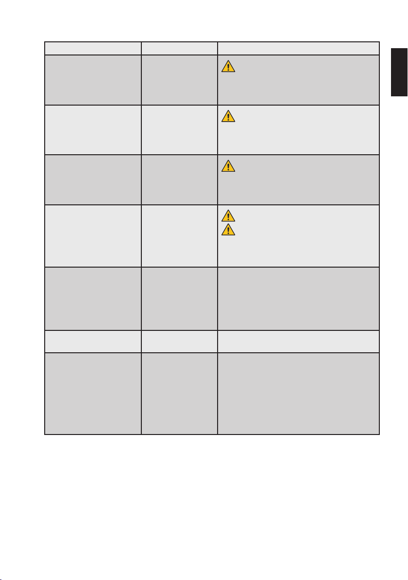
25
Problem Ursache Vorgehen
Rauch oder Feuer am Gerät. Hardwaredefekt.
Gehäuse des Ladegeräts
beschädigt/zerbrochen
Handstück zu heiß, so dass
Sie es nicht in der Hand halten
können.
Flüssigkeitsleck vom Gerät
(Akkumulatorsäure läuft aus)
Das Gerät schaltet nicht ein. • Akku leer.
Das Gerät funktioniert nicht
wie erwartet.
Das Display funktioniert nicht
richtig: dunkel, flackert oder
ganz schwarz
Hardwaredefekt.
Hardwaredefekt.
Akkugehäuse defekt.
• Das Ladegerät ist
nicht richtig in die
Steckdose eingesteckt.
• Ladegerät defekt.
Konfigurationsspeicher
fehlerhaft.
Starke elektrostatische
Entladung.
Brand- und Stromschlagrisiko.
Beenden Sie sofort die Verwendung des Gerätes, trennen Sie es von der Stromversorgung und kontaktieren
Sie das Servicezentrum.
Brand- und Stromschlagrisiko.
Beenden Sie sofort die Verwendung des Gerätes, trennen Sie es von der Stromversorgung und kontaktieren
Sie das Servicezentrum.
Brand- und Stromschlagrisiko.
Beenden Sie sofort die Verwendung des Gerätes, trennen Sie es von der Stromversorgung und kontaktieren
Sie das Servicezentrum.
Brand- und Stromschlagrisiko.
Risiko einer allergischen Reaktion oder Toxizität.
Beenden Sie sofort die Verwendung des Gerätes, trennen Sie es von der Stromversorgung und kontaktieren
Sie das Servicezentrum.
• Laden Sie den Akku wieder auf.
• Prüfen Sie, ob das Ladegerät richtig in die Steckdose eingesteckt ist.
Auf Standardparameter zurücksetzen, wie in Kapitel
„8.6. Werkseinstellungen“ beschrieben.
Beenden Sie sofort die Verwendung des Gerätes, trennen Sie es von der Stromversorgung und warten Sie
5 Minuten.
Schließen Sie das Gerät wieder an die Stromversorgung an und schalten Sie es wieder ein.
Wenn das Problem weiterhin besteht, trennen Sie das
Gerät von der Stromversorgung und kontaktieren Sie
das Servicezentrum.
de
Page 26
26
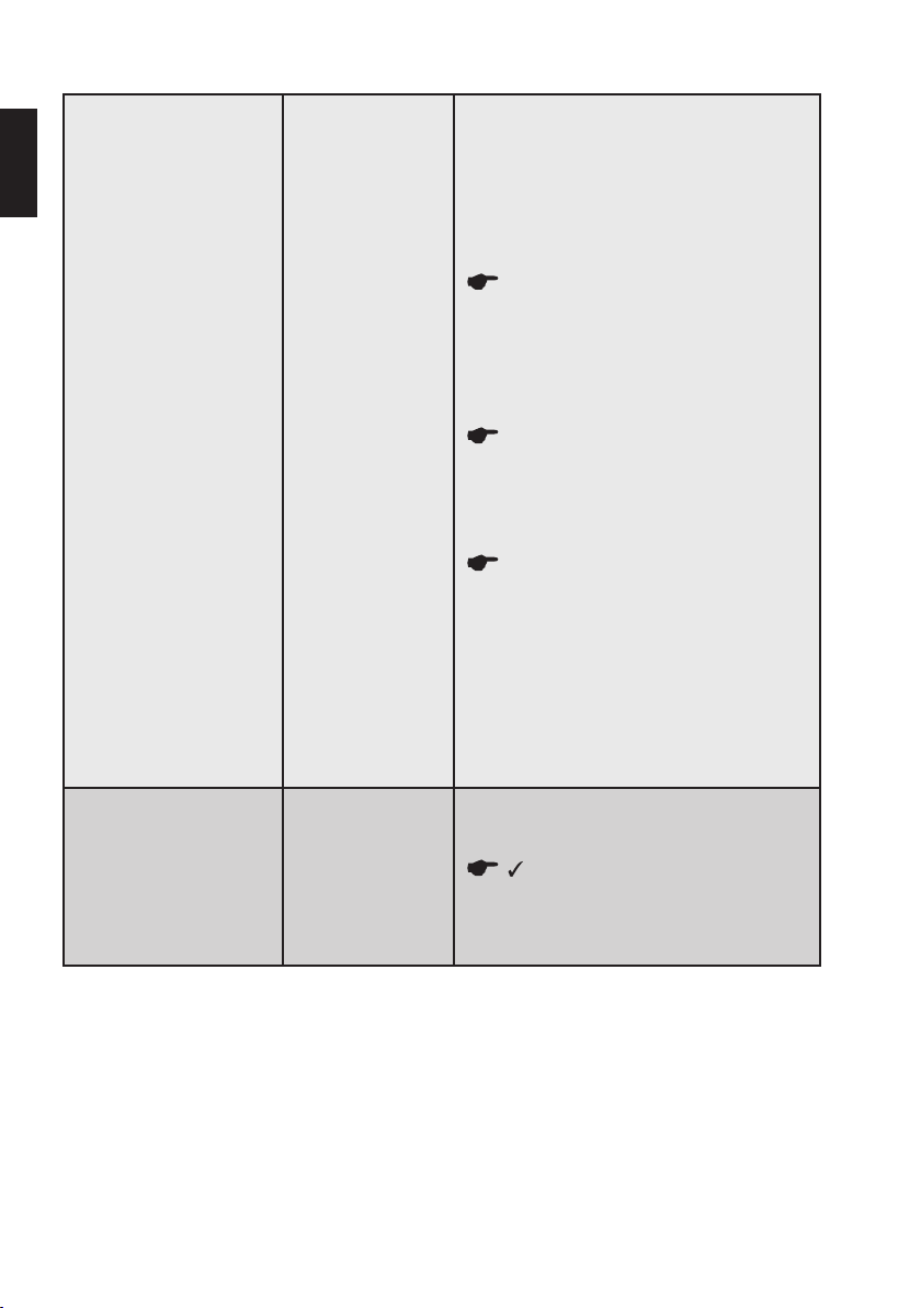
Der Mikromotor startet nicht. • Mikromotorkabel
de
Der Mikromotor lässt sich
nicht mit dem Fußschalter
starten.
nicht richtig angeschlossen.
• VDW6:1 Winkelstück
defekt.
• Mikromotor defekt.
• Starke elektrostatische Entladung
• Fußschalter nicht
richtig angeschlossen.
• Fußschalter defekt.
• Überprüfen Sie, ob das Mikromotorkabel richtig
an das Mikromotorgehäuse und die Steuereinheit
angeschlossen ist.
• Überprüfen Sie, ob das Winkelstück richtig funktioniert und dass es nicht blockiert ist: Entfernen Sie
das Winkelstück vom Mikromotor, setzen Sie eine
Feile in das Winkelstück ein und drehen Sie die Feile
von Hand.
Wenn sich die Feile ohne deutlichen Widerstand
dreht, sollte das Winkelstück richtig funktionieren.
Fahren Sie mit der Fehlersuche fort, um die Ursache
des Problems zu finden. Andernfalls ersetzen Sie das
Winkelstück.
• Überprüfen Sie, ob der Mikromotor einwandfrei
funktioniert: Kalibrieren Sie ohne Winkelstück.
Wenn die Kalibrierung fehlschlägt, stellen Sie
an der Steuereinheit die maximale Drehzahl ein, starten Sie den Mikromotor und lassen Sie ihn mindestens
5 Minuten laufen. Wiederholen Sie die Kalibrierung.
Wenn die Kalibrierung erneut fehlschlägt, wenden Sie
sich an das Servicezentrum.
Wenn die Kalibrierung erfolgreich ist, setzen Sie
das Winkelstück wieder auf den Mikromotor und wiederholen Sie den Kalibriervorgang. Wenn die Kalibrierung erneut fehlschlägt, wenden Sie sich an das Servicezentrum.
• Es ist bekannt, dass eine starke ESD zu einer vorü-
bergehenden Motorstörung führen kann. Wenn das
Motorproblem durch die oben genannten Schritte
nicht behoben wird, fahren Sie mit den Anweisungen zur Fehlerbeseitigung in der Spalte „Das Display
funktioniert nicht richtig“ fort.
• Stellen Sie sicher, dass der Fußschalter richtig mit
dem Gerät verbunden ist, und drücken Sie den Fußschalter erneut.
Wenn der Mikromotor nicht startet, starten
Sie ihn durch 1,5 Sekunden langes Drücken der Taste
CONFIRM (Bestätigen). Wenn der Mikromotor so startet, ersetzen Sie den Fußschalter. Andernfalls wenden
Sie sich an das Servicezentrum.
Page 27
27
Ladegerät funktioniert nicht
richtig.
De Akku entlädt sich zu
schnell.
CALIBRATION ERROR 1. Mikromotor nicht rich-
CALIBRATION ERROR 2. VDW6:1 Winkelstück
So erreichen Sie das Servicezentrum:
VDWGmbH
Vertriebsservice
Hoferstr. 1
81737 München
Deutschland
Telefon: +49 89 62734555
Fax: +49 89 62734374
[email protected]
www.vdw-dental.com/service
Ladegerät defekt.
• Der Akku ist nicht
richtig aufgeladen.
• Akku oder Ladegerät
defekt.
tig angeschlossen.
fehlerhaft; übermäßiger
Widerstand.
Ersetzen Sie das mitgelieferte Ladegerät nicht
durch einen anderen Netzstecker.
• Stellen Sie sicher, dass der Stecker richtig in das
Gehäuse des Ladegeräts eingesteckt ist.
• Stellen Sie sicher, dass das Ladegerät richtig in
Steckdose und Gerät eingesteckt ist.
• Wenden Sie sich für den Austausch an das Servicezentrum.
• Laden Sie den Akku vollständig auf, achten Sie dabei
auf die Akku-LED. Siehe Kapitel „8.2.5. Akku“.
• Wenden Sie sich für den Austausch an das Servicezentrum.
Kontrollieren Sie, ob der Mikromotor richtig angeschlossen ist und versuchen Sie die Kalibrierung
erneut.
Wenn das Problem dadurch nicht behoben wird,
befolgen Sie die Anweisungen zur Fehlerbehebung bei
„Der Mikromotor startet nicht“.
Befolgen Sie die Anweisungen zur Fehlerbehebung bei
„Der Mikromotor startet nicht“.
de
Page 28

28
11. Meldung eines Zwischenfalls
Wenn es zu einem Unfall kommt, der direkt oder indirekt
mit dem Gerät zusammenhängt, informieren Sie sofort
de
den Hersteller und die zuständige Behörde in Ihrem Land
und in dem des Patienten (falls abweichend).
Per E-Mail:
MunichDEU-VDW-ComplaintDepartment@vdw-dental.
com / [email protected]
Per Fax:
+49 89 62734 - 379
Per Post:
VDWGmbH
Reklamationsabteilung
Bayerwaldstr. 15
81737 München
Deutschland
12. Entsorgung von Abfallteilen
Das Gerät darf nicht im Hausmüll entsorgt werden. Wenn
Sie das Gerät endgültig entsorgen möchten, halten Sie
die in Ihrem Land geltenden nationalen Vorschriften für
die Entsorgung elektrischer Geräte ein. Für weitere Einzelheiten wenden Sie sich direkt an die VDWGmbH.
HINWEISE
Informationen zur ordnungsgemäßen Entsorgung der endodontischen Instrumente finden
Sie in den Anweisungen des Herstellers.
Vor der Entsorgung dürfen das Gerät und seine Zubehörteile nicht verunreinigt sein und müssen entsprechend
der Anweisungen in Kapitel 9 „Reinigung, Desinfektion
und Sterilisation“ vollständig wiederaufbereitet worden
sein.
Elektro- und Elektronik-Altgeräte von Kunden mit Sitz in
der Europäischen Union können zum Recycling gemäß
den WEEE-Vorschriften an VDW gesendet werden. Die
Kosten für das Recycling, ausgenommen der Versandkosten, werden vom VDW übernommen.
Page 29

29
13. Garantie
Zusätzlich zu der Gewährleistung aus dem Kaufvertrag mit dem Dentalhandel gewährt die VDWGmbH
den Kunden direkt die folgende Servicegarantie:
1) VDW garantiert die einwandfreie Herstellung des
Produkts, die Verwendung von Materialien höchster
Qualität, die Durchführung aller erforderlichen Tests und
die Erfüllung aller geltenden einschlägigen Gesetze und
Bestimmungen in Zusammenhang mit dem Produkt.
Die volle Funktionsfähigkeit von VDW.SILVER
wird durch eine Garantie von 36 Monaten abgedeckt
(Ausnahme: Das Winkelstück wird durch eine Garantie
von 12 Monaten abgedeckt), deren Lauf mit dem Datum
der Lieferung an den Kunden beginnt (gemäß der vom
Verkäufer beim Verkauf ausgestellten Lieferpapiere, welche die Seriennummer des Produkts enthalten).
Der Kunde hat nur innerhalb des Garantiezeitraums
Anspruch auf Garantieleistungen und nur unter der Voraussetzung, dass VDW über den Defekt innerhalb von
zwei Monaten, nachdem er festgestellt wurde, schriftlich
informiert wurde.
2) Im Falle einer berechtigten Reklamation wird das
VDW Service-Center München die Reparatur innerhalb
von 3 Werktagen ab Eingang bei der VDWGmbH in München zuzüglich der Transportzeit für die Rücksendung
zum Kunden vornehmen.
3) Diese Garantie deckt nur den Austausch oder die
Reparatur einzelner Komponenten oder Teile mit Fabrikationsfehlern ab. Die Kosten für die Aussendung von
Personal des Dentalfachhändlers für technische Unterstützung zum Kunden und/oder die Kosten des Kunden
für die Verpackung werden von VDW nicht erstattet. Weitere Ansprüche des Kunden, die über die Reparatur hinausgehen, z. B. Schadenersatzansprüche, sind ausgeschlossen. Diese Garantie schließt keine Entschädigung
für direkte oder indirekte Verletzungen von Personen
oder Materialschäden jedweder Natur ein. Der Kunde hat
keinen Anspruch auf Entschädigungen für Ausfallzeiten
des Geräts.
®
RECIPROC®
4) Die Garantie erstreckt sich nicht auf Schäden, bei
denen VDW nachweist, dass sie durch Versäumnisse
des Benutzers bezüglich der normalen Wartung (siehe
Gebrauchsanweisung) entstanden sind, insbesondere
beim Laden, Entladen und der Pflege des Akkus gemäß
Gebrauchsanweisung sowie bei der sorgfältigen und
regelmäßigen Pflege des Winkelstücks entsprechend
der gesonderten Winkelstück-Gebrauchsanweisung.
Von der Garantie explizit ausgeschlossen sind Defekte
aufgrund von:
• Schäden während des Transports zu VDW zu Reparaturzwecken,
• Schäden durch umweltbedingte Ereignisse wie etwa
Blitzschlag, Feuer und/oder Feuchtigkeit.
Diese Garantie verliert automatisch ihre Gültigkeit, wenn
das Produkt unsachgemäß repariert, modifiziert oder auf
andere Weise vom Benutzer, nicht autorisierten Personen
oder dem Personal Dritter manipuliert wurde.
5) Die Garantie ist nur gültig, wenn dem zur Reparatur
eingesandten Gerät die Rechnung mit der Bestätigung
des Lieferdatums des Produktes beigefügt wird.
6) Gesetzliche Ansprüche, etwa aus dem Produkthaf-
tungsrecht, oder Ansprüche gegenüber demjenigen, von
dem der Kunde das Produkt erworben hat, insbesondere
gegenüber dem Dentalhandel, bleiben unberührt.
de
Page 30
30
14. Technische Daten
HERSTELLER VDWGmbH, Bayerwaldstr. 15
de
MODELL VDW.SILVER® RECIPROC® – REF V04 1163 000 000
MEDIZINPRODUKTE KLASSIFIZIERUNG Klasse IIa, gemäß Anhang IX, Regel IX, 93/42/EWG und
ELEKTRISCHE SCHUTZKLASSE Elektrische Isolierung Klasse II gemäß IEC60601-1
ANWENDUNGSTEIL BF (Winkelstück)
IP GRADE Steuereinheit: IP20
ABMESSUNGEN Steuereinheit: 209 x 89 x 93mm
MATERIAL Gehäuse Steuereinheit: PC/ABS
GEWICHT Steuereinheit, Kabel, Mikromotor und Winkelstück:
WINKELSTÜCK Kompatibel mit endodontischen Feilen mit einem
INTERNER AKKU NiMH-Akku, 2000mAh, 6Vdc
LADEGERÄT/NETZTEIL 100 -240Vac, 47-63 Hz, 0,8A max
LEISTUNGSBEDARF STEUEREINHEIT 12Vdc, 2,5A max
81737 München, Deutschland
Änderungsrichtlinie 2007/47/EWG
Mikromotor: IP24
Fußschalter: IPX1
Mikromotor: 90,5mm, Ø 23,5mm mit Kabel 1,8m
lang
Fußschalter: Ø 10cm mit Kabel 1,8m lang
Mikromotor: Aluminium
1,1kg
Ladegerät: 0,237kg
Fußschalter: 0,113kg
Schaftdurchmessser von 2,334 - 2,35mm, Schafttyp 1
gemäß ISO1797:2017
Page 31
31
0123
AUSGANGSLEISTUNG ZUM MIKROMOTOR 30W max
BETRIEBSMODUS Kein Dauerbetrieb
Betriebszyklus: 3min EIN/ 1min AUS
DREHMOMENTBEREICH 20-410gcm (≈ 0,2-4,1Ncm); ± 20 % im Rotations-
DREHZAHL AM MIKROMOTORSCHAFT 1500 -6000Upm (±10 %) im Rotationsmodus
SICHERHEITSSTUFE IN DER NÄHE VON BRENNBAREM
ANÄSTHESIEGAS, GEMISCHEN ODER SAUERSTOFF
NORMALE BETRIEBSBEDINGUNGEN +15°C/+35°C; RL < 80 % (nicht kondensierend);
BEDINGUNGEN FÜR TRANSPORT UND LAGERUNG -20°C/+50°C; RL:20-90 %;
WESENTLICHE LEISTUNGSMERKMALE Keine wesentliche Leistung (entsprechend
LEBENSDAUER Steuereinheit, Mikromotor, Winkelstück: 3 Jahre
Dieses Produkt trägt die CE-Kennzeichnung gemäß den Bestimmungen der Richtlinie 93/42/EWG
des Rates vom 14. Juni 1993 über Medizinprodukte.
Dieses Produkt wurde erstmals 2010 mit der CE-Kennzeichnung versehen
modus
Nicht geeignet für die Verwendung in der Nähe von entflammbaren Anästhesiegasgemischen oder Sauerstoff
Luftdruck: 80 - 106kPa
Luftdruck: 50 - 106kPa
MDD93/42/EWG und Änderungsrichtlinie
2007/42/EWG)
de
Page 32
32
15. Dr’sChoice Tabellen
Tragen Sie den Feilentyp und die ausgewählten Werte Ihrer benutzerdefinierten Drehmoment- und Drehzahleinstellungen in die folgende Tabelle ein (Einzelheiten siehe Kapitel „8.5.3. Dr’sChoice (nur im Rotationsmodus)“):
de
Feilenposition Feilentyp gcm rpm
01
02
03
04
05
06
07
08
09
10
11
12
13
14
15
Dr´s Choice Standardeinstellungen:
Feilenposition gcm rpm
01 30 300
02 50 300
03 70 300
04 100 300
05 120 300
06 150 300
07 170 300
08 200 300
09 220 300
10 250 300
11 270 300
12 300 300
13 320 300
14 350 300
15 400 300
Zur Wiederherstellung der Standardparameter siehe Kapitel „8.6. Werkseinstellungen“.
Page 33
33
Elektromagnetische Aussendungen und Störfestigkeit
Das Gerät erfüllt alle Anforderungen der IEC 60601-1-2:2014 (4. Ausgabe) und der vorherigen Ausgabe:
IEC60601-1-2:2007 (3. Ausgabe).
WARNHINWEIS
• Die Verwendung anderer als der als Zubehör gelieferten oder aufgeführten Teile kann die EMV-Eigenschaften negativ beeinflussen.
• Tragbare HF-Kommunikationsgeräte (einschließlich Zubehörteile wie Antennenkabel und externe Antennen)
sollten mit einem Mindestabstand von 30 cm (12 Zoll) zu jedem Teil des Gerätes verwendet werden. Andern
falls könnte die Leistung dieses Gerätes beeinträchtigt werden.
Das Gerät ist für den Einsatz in den in Kapitel 3 genannten Umgebungen bestimmt und die grundlegende Sicherheit
unter den nachstehend beschriebenen elektromagnetischen Umgebungsbedingungen gewährleistet.
Einhaltung der Vorschriften für elektromagnetische Aussendungen
Aussendungsmessung
HF-Aussendungen
CISPR 11
HF-Aussendungen
CISPR 11
Oberschwingungen
IEC61000-3-2
Spannungsschwankungen/Flicker
IEC61000-3-3
Übereinstim-
mung
Gruppe 1
Klasse A
Entspricht
Klasse A
Entspricht
Elektromagnetische Umgebung – Leitlinien
Das Gerät nutzt HF-Energie nur für seine interne Funktion. Deshalb sind
seine HF-Aussendungen sehr gering und Störungen in der Nähe befindlicher elektronischer Geräte unwahrscheinlich.
Aufgrund seiner Aussendungsmerkmale ist dieses Gerät für die Verwendung in professionellen Gesundheitseinrichtungen und Krankenhäusern
geeignet. Bei Verwendung in einer Wohnumgebung bietet dieses Gerät
möglicherweise keinen ausreichenden Schutz für Hochfrequenz-Kommunikationsgeräte. Der Benutzer muss dann eventuell Maßnahmen zur
Risikominderung, wie eine Neupositionierung oder Neuausrichtung des
Gerätes, vornehmen.
-
de
Page 34

Störfestigkeitsprü-
de
Entladung statischer
Elektrizität (ESD)
IEC61000-4-2
Schnelle transiente
elektrische Störgrößen/Bursts
IEC61000-4-4
Stoßspannung
(Surge)
IEC61000-4-5
Spannungseinbrüche
IEC61000-4-11
Spannungsunterbrechungen
IEC61000-4-11
Magnetfeld bei Versorgungsfrequenz
IEC61000-4-8
Geleitete HFStörgrößen
IEC61000-4-6
fung
34
Einhaltung der Vorschriften für elektromagnetische Störfestigkeit
IEC60601-1-2
Prüfpegel
Übereinstimmungspegel
Elektromagnetische Umgebung –
Der Fußboden sollte aus Holz,
±8 kV Kontaktentladung
±15 kV Luftentladung
Beton oder Fliesen sein. Bei syn-
thetischen Fußbodenbelägen sollte
die relative Luftfeuchtigkeit min-
destens 30 % betragen.
±1kV für Ein-/Ausgangsleitungen 100kHz Wieder-
holungsfrequenz
±2kV für Netzleitungen 100kHz Wiederholungs-
frequenz
±1kV Gegentakt
Das Medizingerät ist für die
Verwendung in professionellen
Gesundheitseinrichtungen geeig-
net.
(±2kV Gleichtakt; Fall nicht anwendbar auf elektrisch isolierte ME Geräte der Klasse II)
0 % U
während 0,5 Perioden bei 0°, 45°, 90°, 135°,
T
180°, 225°, 270° und 315°
0 % U
während 1 Periode und 70 % UT während
T
25/30Perioden. Einzelphase bei 0°
Das Medizingerät ist für die
Verwendung in professionellen
Gesundheitseinrichtungen geeig-
net. Wenn das Gerät auch bei
Stromunterbrechungen weiter
ungestört funktionieren soll, wird
empfohlen, das Gerät mittels einer
während 250/300Perioden
0 % U
T
unterbrechungsfreien Stromver-
sorgung oder einer Batterie zu
betreiben.
Das Medizingerät ist für die
30A/m (50Hz oder 60Hz)
Verwendung in professionellen
Gesundheitseinrichtungen geeig-
net.
Tragbare HF-Kommunikationsge-
räte (einschließlich Zubehörteile
wie Antennenkabel und externe
3Vrms (0,15MHz - 80MHz)
6Vrms in ISM-Bändern
80 % AM bei 1kHz
Antennen) sollten mit einem Min-
destabstand von 30 cm (12 Zoll) zu
sämtlichen Teilen des Produktes,
einschließlich Kabeln, verwendet
werden. Andernfalls könnte die
Leistung dieses Gerätes beein-
trächtigt werden.
Leitlinien
Page 35
35
Gestrahlte HFStörgrößen
IEC61000-4-3
Nachbarschaftsfelder von drahtlosen
HF-Kommunikationsgeräten
IEC61000-4-3
3V/m 80MHz - 2,7GHz
80 % AM bei 1kHz
9V/m
710MHz, 745MHz, 780MHz, 5.240MHz,
5.550MHz, 5.785MHz
27V/m
385MHz
28V/m
Tragbare HF-Kommunikationsgeräte (einschließlich Zubehörteile
wie Antennenkabel und externe
Antennen) sollten mit einem Mindestabstand von 30 cm (12 Zoll) zu
sämtlichen Teilen des Produktes,
einschließlich Kabeln, verwendet
werden. Andernfalls könnte die
Leistung dieses Gerätes beeinträchtigt werden.
450MHz, 810MHz, 870MHz, 930MHz, 1.720MHz,
1.845MHz, 1.970MHz, 2.450MHz
Hinweis: U
ist die Netzwechselspannung vor der Anwendung des Prüfpegels.
T
Empfohlene Mindestschutzabstände zwischen tragbaren bzw. mobilen HF-Kommunikationsgeräten und dem Gerät
gemäß IEC60601-1-2 Ausg.3
Das Gerät ist zum Betrieb in einer elektromagnetischen Umgebung vorgesehen, in der gestrahlte HF-Störgrößen
kontrolliert werden. Der Käufer bzw. der Anwender des Gerätes kann zur Vermeidung elektromagnetischer Störungen beitragen, indem er zwischen dem Gerät und tragbaren bzw. mobilen HF-Kommunikationsgeräten (Sendern)
einen von Ausgangsleistung und Frequenz der Kommunikationsgeräte abhängigen Mindestabstand entsprechend
den nachstehenden Empfehlungen einhält.
Maximale Ausgangsnenn-
leistung des Senders (W)
Von 150kHz bis 80MHz
Schutzabstand entsprechend der Frequenz des Senders (m)
d = 1,2*√P
Von 80MHz bis 800MHz
d = 1,2*√P
Von 800MHz bis 2GHz
d = 1,2*√P
0.01 0.12 0.12 0.23
0.1 0.38 0.38 0.73
1 1.2 1.2 2.3
10 3.8 3.8 7.3
100 12 12 23
Für Sender mit einer anderen maximalen Ausgangsnennleistung als oben angegeben kann der empfohlene Schutzabstand d in Metern (m) mit Hilfe der Gleichung für die betreffende Frequenz des Senders bestimmt werden, wobei
P die maximale Ausgangsnennleistung dieses Senders in Watt (W) nach Angaben des Senderherstellers ist.
HINWEISE
• Bei 80 MHz und 800 MHz gilt der Schutzabstand des jeweils höheren Frequenzbereichs.
• Diese Richtwerte treffen eventuell nicht auf alle Situationen zu. Die Ausbreitung elektromagnetischer Wel
-
len wird von der Absorption und Reflektion durch Bauten, Gegenstände und Personen beeinflusst.
de
Page 36

0123
VDWGmbH
Bayerwaldstr. 15
81737 München
Deutschland
Tel. +49 (0) 89 62734-0
Fax +49 (0) 89 62734-304
[email protected]
MDESILVERDFUWEB Vol.1 Rev.8 / 10.05.2019
Page 37
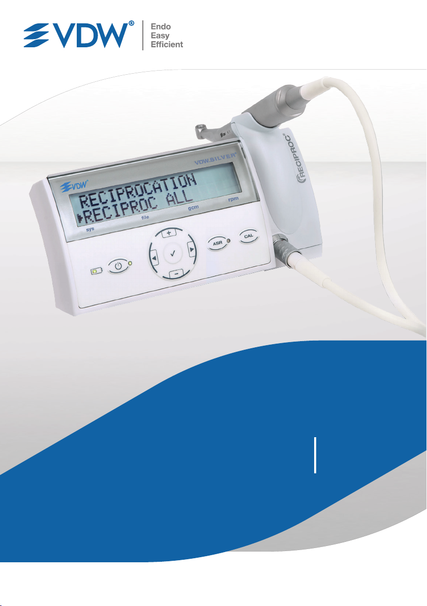
VDW.SILVER
RECIPROC
®
®
Operating
Manual
vdw-dental.com
Page 38

2
Congratulations on your purchase of the
VDW.SILVER
en
Endodontic products and services are the focus
®
RECIPROC® endo motor.
of VDW GmbH's business operations. Constantly
remaining in close cooperation with international
universities and endodontists allows us to develop
innovative concepts, products and systems to
make dentist's work simpler, easier and more
effective.
By having purchased the VDW.SILVER
®
endo motor, you have acquired a product which
has been developed and tested with the utmost
care, meeting event the highest expectations in
terms of functionality and operation.
This manual is available in additional languages
upon request.
This manual has been created with the greatest
care, but even with all our efforts, errors can never
be entirely excluded. Suggestions for improvement
are welcome anytime.
Please contact VDW GmbH with any related
comments or suggestions you may have.
VDW GmbH
Bayerwaldstr. 15
81737 Munich
Germany
RECIPROC®
Phone +49 89 62734-0
Fax +49 89 62734-304
[email protected]
www.vdw-dental.com
Page 39

Table of Contents
3
1. Before Use .............................................. 4
2. Identification of Symbols ....................... 5
2.1. Symbols used in these Instructions for
Use .......................................................... 5
2.2. Symbols used on Packaging, Device
and Components ..................................... 5
3. Intended Use, Intended User and
Patient Population ..................................6
4. Contraindications ...................................6
5. Warnings ...............................................6
6. Precautions ............................................7
7. Adverse Reactions ................................. 7
8. Step-by-Step Set-Up .............................. 7
8.1. Supplied Components and Accessories ..8
8.2. Getting Started ........................................9
8.2.1. Preparation ..............................................9
8.2.2. Overview of Connections .......................... 9
8.2.3. Battery Charger ...................................... 10
8.2.4. Micromotor, VDW 6:1 Contra-Angle and
Foot Pedal ..............................................11
8.2.5. Battery ................................................... 11
8.3. User Interface ........................................12
8.3.1. Keypad ...................................................12
8.3.2. Display ...................................................13
8.3.3. Foot Pedal .............................................. 13
8.3.4. Audible Signals ......................................14
8.3.5. File Library ............................................. 14
8.4. Operation ...............................................15
8.4.1. Power On, Standby Mode, Power Off ......15
8.4.2. CAL: Calibration ......................................16
8.4.3. ASR: Automatic Stop Reverse .................16
8.5. Selecting File Systems/Files .................17
8.5.1. Rotary Mode........................................... 17
8.5.2. Changing Torque and Rotational Speed
(Rotary Mode only) ................................. 18
8.5.3. Dr's Choice (Rotary Mode only) ............... 19
8.5.4. Reciprocating Mode ............................... 19
8.6. Default Parameters ...............................20
9. Cleaning, Disinfection and
Sterilization .......................................... 20
9.1. Pre-Treatment (to be performed after
each use) ...............................................21
9.2. Manual Cleaning and Disinfection.........22
9.3. Inspection/Maintenance ........................23
9.4. Packing .................................................23
9.5. Sterilization ........................................... 23
9.6. Storage .................................................. 24
9.7. Material Durability .................................24
10. Maintenance and Troubleshooting ...... 24
10.1. Maintenance .........................................24
10.2. Troubleshooting .....................................24
11. Adverse Event Notification .................. 28
12. Disposal of Waste Parts ....................... 28
13. Warranty ...............................................29
14. Technical Data ...................................... 30
15. Dr’s Choice Tables ................................32
Electromagnetic Emissions and
Immunity ..............................................33
en
Page 40
4
1. Before Use
The information provided in this document is
en
necessary to operate the VDW.SILVER
safely to prevent injuries for the users and the
patients.
Read carefully all the instructions to be followed
before, during and after the use of the device.
This document dœs not comprehend the
Directions for Use of VDW 6:1 contra-angle and
of the endodontic files. Read carefully also these
documents for all the information regarding
these devices to be used in combination with
VDW.SILVER
®
RECIPROC®.
Keep this manual and the other referenced at hand
all time. Keep the original packaging as it can be
used for shipping or storing the device.
WARNINGS
• The use of accessories, other than
those specified, except for components
sold by the manufacturer as replacement
parts, is not allowed. Use only the original
accessories and spare parts. The use of
cables and accessories other than those
specified may negatively affect EMC
performance of the device.
• DO NOT open the console (no serviceable
parts inside).
• DO NOT modify the equipment and/or
any of its accessories. Modifications of
this medical device are not allowed. If any
of the components need to be replaced,
contact the service centre.
• Battery charger must be disconnected
from electrical outlet for the purposes of
maintenance of electrical equipment, in
the case of malfunction or when the device
is left unattended.
®
RECIPROC®
If any serious incident occurs that is directly or
indirectly related to the device, report it immediately
to the manufacturer and the competent authority of
your country and of the country where the patients
is established (if different). For information on how
to report and adverse event, refer to Chapter "11.
Adverse Event Notification".
Page 41
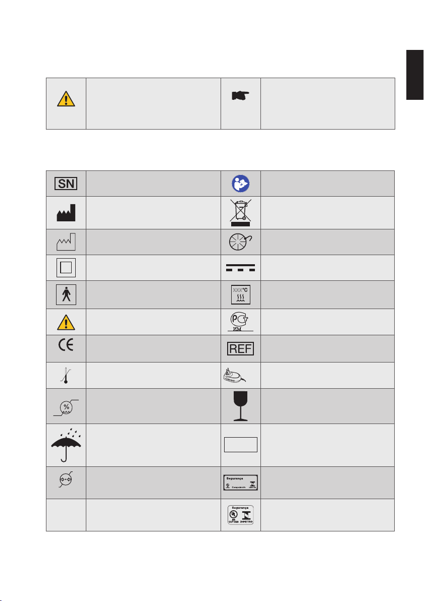
2. Identification of Symbols
䣚䣚䣚
05
Model:
TR30RAM120
90%
20%
5
2.1. Symbols used in these Instructions for Use
WARNING
Failure to follow all instructions
correctly during use can damage the
product or endager user/patients.
Additional information; explanation of
operation and performance.
NOTE
2.2. Symbols used on Packaging, Device and Components
Serial number
Manufacturer
Date of manufacture Foot pedal connection
Class II product
Type BF applied part
Warning
CE marking and reference number of
the Notified Body
0123
+ 50° C
- 20° C
Temperature limitation
Refer to Instructions For Use
(mandatory action)
Not to be disposed of with ordinary
waste
Direct current
(battery charger supply connection)
Steam-sterilizable up to xxx °C,
indicated on the symbol
Gost symbol, product meets Russian
safety standards (GOST-R).
Catalogue number (reorder number)
Operate the device only with the
provided battery charger
en
Humidity limitation Fragile!
IP water and dust protection level:
Keep dry!
IPN
the two digits (N1 and N
1N2
the grade of protection from solid
) indicate
2
and liquid objects, respectively
106 kPa
50 kPa
Atmospheric pressure limitation
®
INMETRO symbol on packaging,
product meets Brazilian security
standards
INMETRO symbol on device,
®
product meets Brazilian security
standards
Page 42
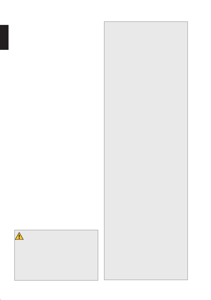
6
3. Intended Use, Intended User and Patient Population
en
FOR DENTAL USE ONLY!
The VDW.SILVER® RECIPROC® is a medical
device in accordance with the Medical Device
Directive 93/42/EEC, amended with the Directive
2007/47/EC. The endomotor is used for dental
root canal treatment using endodontic instruments
in torque-controlled continuous rotation and in
reciprocating movement.
This device has to be used only in hospitals,
general practices or dental clinics by qualified
dental professionals (dentists and endodontists).
Do not use the device for implants or any other
dental procedure other than endodontics.
All patients can be treated with VDW.
®
SILVER
RECIPROC® without restriction in terms of
gender, origin and age, excluding children.
4. Contraindications
The use of VDW.SILVER® RECIPROC® is
contraindicated in case the patient/user carries
active medical implants (pacemaker, cochlear
implants,…).
Safety and effectiveness have not been established
in pregnant or breast-feeding women and children.
Clinical judgement needs to be exercised by the
end user of the device.
5. Warnings
Read the following warnings before use.
WARNINGS
• DO NOT use this device in presence of
flammable anesthetics or oxidizing gases
(such as nitrous oxide N
or near volatile solvents (such as ether or
alcohol), as explosion may occur.
O and oxygen)
2
• Modifications of this medical device are
not allowed. If any of the components need
to be replaced, contact the service centre.
• Do not connect VDW.SILVER
RECIPROC
Do not connect any device to VDW.
SILVER
®
with other devices or systems.
®
RECIPROC® through the USB port.
®
The USB port is exclusively intended for
use by authorized personnel for purposes
of maintenance or software updates.
• The VDW.SILVER
®
RECIPROC
®
components are not delivered disinfected
or sterilized: components such as the
central unit, the micromotor and the
micromotor cable must be disinfected prior
first use and appropriately reprocessed
after every additional use. The VDW 6:1
contra-angle must be sterilized before first
use and fully reprocessed after each use.
• Use only the provided battery charger.
• Battery charger must be all time
accessible for its prompt disconnection
from the power outlet.
• Use only the VDW 6:1 contra-angle with
the device. The precision of the torque and
rotational speed is ensured only if the VDW
6:1 contra-angle is used.
• Should any liquid exit from VDW.SILVER
RECIPROC
®
that might be attributed to
®
a leaking battery, stop using the device
immediately and disconnect it from the
power outlet. Contact the service centre.
• Should any malfunction occur when
using the device, switch the micromotor
off, disconnect the device from the power
outlet and contact the service centre.
• Follow the instructions given in the file
manufacturer’s manual and in the operating
instructions of the VDW 6:1 contra-angle
when using endodontic instruments.
• The use of a rotary file in reciprocating
mode may lead to its breakage. Never use
rotary files in reciprocating mode. Check
the mode shown on the display before use.
Page 43

7
• The use of a reciprocating file in rotary
mode may lead to its breakage. Never use
reciprocating files in rotary mode. Check
the mode shown on the display before use.
• Allowed torque and rotational speed
values can be changed by the file
manufacturer without prior notice. The
preset values must therefore be checked
in the library before use. The values shown
on the display are only precise and reliable
in combination with a correctly maintained
and lubricated VDW 6:1 contra-angle.
• Do not insert any files during calibration.
Risk of injury, as the micromotor changes
rotational speed from the minimum to the
maximum value during calibration. Always
calibrate the VDW 6:1 contra-angle before
using it and without any file.
• Do not insert anything in the micromotor.
Do not lubricate the micromotor as
lubrication can damage it and affect its
function.
• Gloves and a rubber dam are mandatory
during treatment with VDW.SILVER
RECIPROC
®
.
®
WARNINGS
• DO NOT use this device in presence of
flammable anesthetics or oxidizing gases
(such as nitrous oxide N
or near volatile solvents (such as ether or
O and oxygen)
2
en
alcohol), as explosion may occur.
• Take the following precautions to avoid
general device malfunctions in case of
electromagnetic disturbances:
- The use of parts other than those
supplied or listed as accessory may
negatively affect EMC performance.
- Refer always to the information
listed in the chapter “Electromagnetic
Compatibility”.
- In case of a device malfunction,
presumably caused by electromagnetic
disturbances, first verify the cabling,
and then move any portable RF
communications equipment and mobile
devices placed nearby as far away as
possible to rule out interference.
- Stop using the device if the
electromagnetic disturbances persist
and contact the service centre for
assistance.
6. Precautions
Read the following precautions before use.
The manufacturer declines any responsibility
in case of use of VDW.SILVER
applications other than those specified in this
Directions for Use.
®
RECIPROC® for
7. Adverse Reactions
There are no known adverse reactions.
8. Step-by-Step Set-Up
This chapter contains all necessary information
regarding the installation and operation of
VDW.SILVER®RECIPROC®.
Page 44
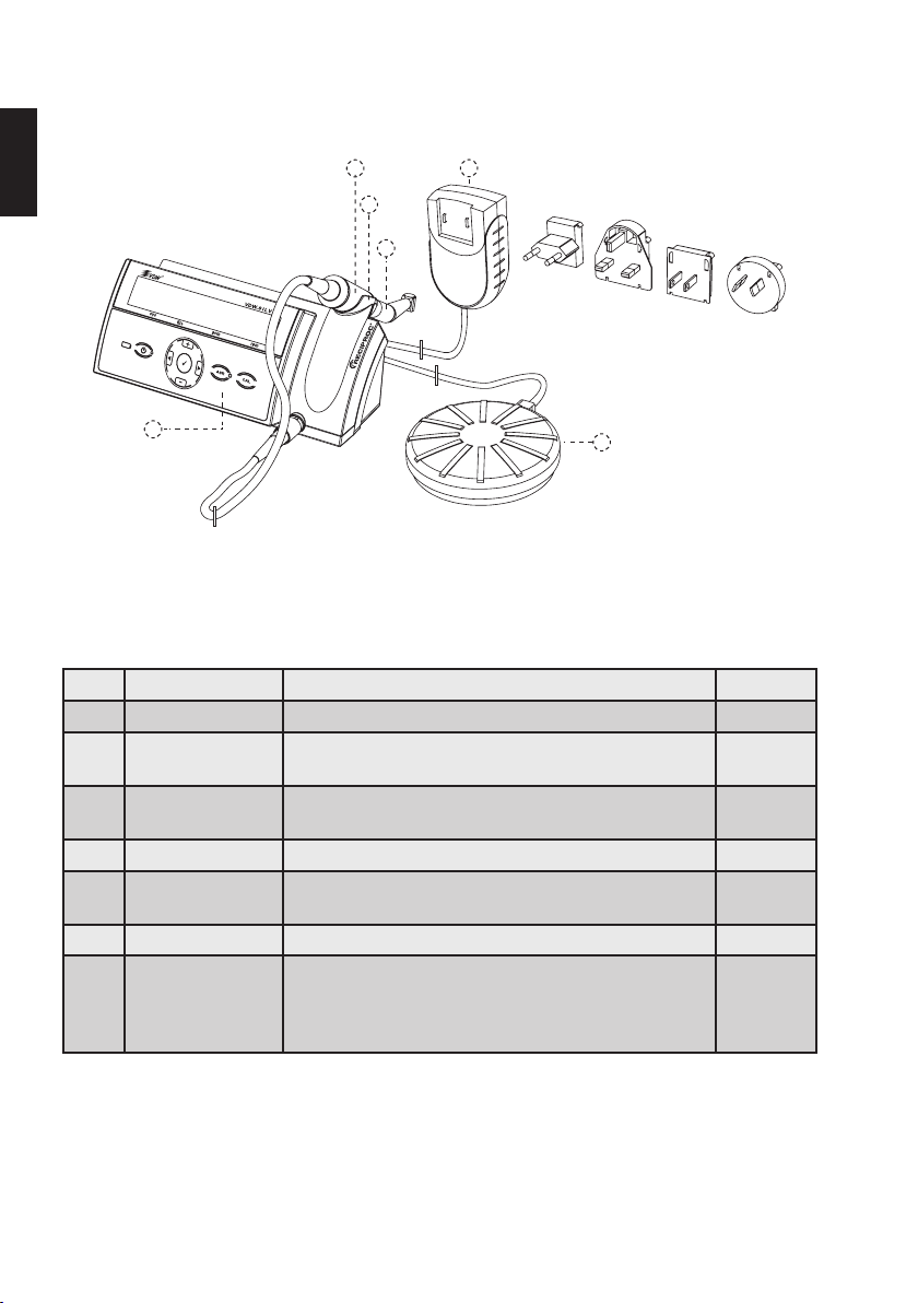
8
(
8.1. Supplied Components and Accessories
The VDW.SILVER®RECIPROC® is supplied with the components listed below:
en
,
)
+
'
Fig. 1 VDW.SILVER®RECIPROC
®
*
Part# REF Item Description Quantity
®
1) V04 1163 000 000 VDW.SILVER
RECIPROC® device 1
2) - Micromotor with cable and connector
(cable length 1.8m)
3) V041 079 000 000 VDW 6:1 contra-angle (packed separately with
accompanying operating instructions
4) V041 107 000 510 Foot pedal (cable length 1.8 m) 1
5) V041 107 000 517 Battery charger (with ferrite ring) with interchangeable
EU, UK, USA, AUS plug adaptors (cable length 1.8 m)
6) - Handpiece holder 1
®
VDW.SILVER
RECIPROC® user manual
User manual can be downloaded at
https://www.vdw-dental.com/en/service/informationmaterial/directions-for-use/
1
1
1
1
Page 45
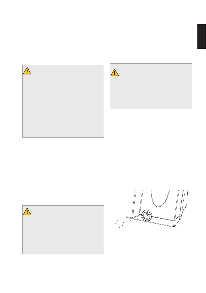
9
8.2. Getting Started
8.2.1. Preparation
1) Carefully remove the central unit and the
accessories from the packaging and set them on a
flat surface in the desired location. Pay attention to
the environmental specifications listed in Chapter
"14. Technical Data" when choosing the location.
WARNING
The device requires special
safety precautions with regard to
electromagnetic compatibility (EMC), and
the EMC information contained in this
manual must be strictly adhered to during
installation and operation. It is especially
important not to use the device near
fluorescent lamps, radio transmitters or
remote controls, portable or mobile radio
frequency communications equipment.
2) After opening the package and before
beginning installation, check the device for
possible damage and for missing parts. Notify the
supplier within 24 hours after receiving the device
about any missing parts or damage in transit.
3) Check that the device serial number on
the bottom of the central unit matches the one
indicated on the package and reported on the
shipping documents.
4) Check that the serial number of the VDW6:1
contra-angle matches the one indicated on its box.
5) Clean, disinfect and sterilize the VDW 6: 1
contra-angle (consult the separate operating
instructions).
6) Clean and disinfect the front of the central
unit, the micromotor and the micromotor cable.
See Chapter "9 Cleaning, Disinfection and
Sterilization".
WARNING
Should any liquid exit from the device,
stop using it immediately and disconnect
the battery charger from the power
outlet. Contact the service centre.
7) Do not place the device in a damp place or
anywhere where it will come into constant contact
with fluids of any kind.
8.2.2. Overview of Connections
Do not pinch the cables of the micromotor, foot
pedal and battery charger and do not pull directly
on the cables when plugging in and unplugging the
components.
Make sure cables are no obstacle and do not limit
mobility.
en
WARNING
The delivered components are neither
sterilised nor disinfected. Follow the
information reported in Chapter "9.
Cleaning, Disinfection and Sterilization"
before operating the device.
A
Fig. 2 Front connection
Front View
A) Connection socket for the micromotor.
Page 46
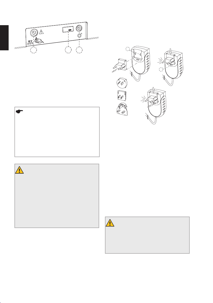
10
8.2.3. Battery Charger
1) Choose the plug adaptor appropriate to your
en
Model:
TR30RAM120
power outlet (see Fig. 4).
B
Fig. 3 Back connections
DC
Back View
B) Connection socket for the battery charger.
C) Connection socket for the foot pedal.
D) USB port for updates (for service personnel
only).
NOTE
The USB port (Fig. 3, D) is used to install
software updates or perform maintenance
on the device. This port has to be used
only by authorized service personnel and
is covered by a USB plug, which shall be
removed by service personnel only.
WARNING
Do not connect VDW.
®
SILVER
RECIPROC® with other devices
or systems. Do not connect any device
to VDW.SILVER
®
RECIPROC® through the
USB port. The USB port is exclusively
intended for use by authorized personnel
for purpose of maintenance and software
updates.
E
F
Fig. 4 Battery charger and plug adaptors
2) Place the appropriate adaptor onto the two
contacts (Fig. 4, E) on the charger and push it
towards the lock button until it clicks into place.
Push the lock button to change the plug adaptor.
3) Connect the cable of the battery charger into
the connection socket (Fig. 3, B) at the back of the
device.
4) Plug the battery charger into the power outlet,
paying attention to have it accessible all time for
a prompt disconnection. The battery will begin
charging.
5) Charge the battery completely before using
the device for the first time. For information on
proper battery care, see Chapter 8.2.5.
WARNING
Battery charger must be all time
accessible for its prompt disconnection
from the power outlet.
Page 47
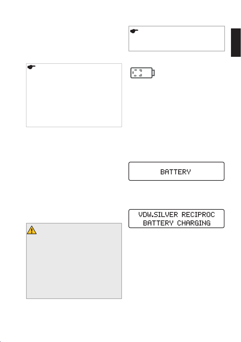
11
8.2.4. Micromotor, VDW 6:1 ContraAngle and Foot Pedal
6) Insert the plug of the micromotor cable into
the connection socket at the front of the central
unit (Fig. 2, A).
NOTE
The connection socket (Fig. 2, A) is a
pushpull connector. Align the red dot
on the male connector to the upright
position to fit the guide of the female
connector. Do not screw the plug into the
socket. To disconnect, pull the metal end
of the cable. Do not twist the plug while
removing it.
7) Remove the black spray adaptor from the
VDW6:1 contra-angle.
8) Insert the VDW 6:1 contra-angle into the
micromotor (see also the separate operating
instructions for the VDW6:1 contra-angle).
9) Insert the foot pedal into its connection socket
(Fig. 3, C) at the back of the central unit.
8.2.5. Battery
The VDW.SILVER® RECIPROC® runs on a NickelMetal Hydride (NiMH) battery. This chapter provides
the information regarding proper battery handling.
NOTE
Fully charge the battery prior to first use.
Battery LED indicator
The battery LED indicator uses
three different colours to display
current battery status:
Green: Indicates a battery capacity between 20
and 100%.
Flashing red: Battery needs to be charged. Battery
power will run out in few minutes.
If the battery LED begins to flash red during
operation, connect the device to the battery
charger immediately as the device will otherwise
shut down during treatment.
The battery warning is a HIGH priority signal.
Before the motor shuts off, a warning alarm will
sound for 22 seconds at two different frequencies
and the following message will appear:
Flashing orange: The charger is correctly
connected and the battery is charging. The
following message will appear on the display:
en
WARNINGS
• Do not open the device in any case. No
serviceable parts inside. If the battery has
to be replaced, contact the service centre.
• Should any liquid exit from VDW.SILVER
RECIPROC
®
that might be attributed to
a leaking battery, stop using the device
immediately and disconnect it from the
power outlet. Contact the service centre.
VDW.SILVER® RECIPROC® can be used normally
while charging without significantly lengthening
the time needed to recharge. The charger is strong
enough to supply the micromotor with electricity
®
directly.
Once the battery is fully charged, the battery LED
light will turn green again.
Page 48
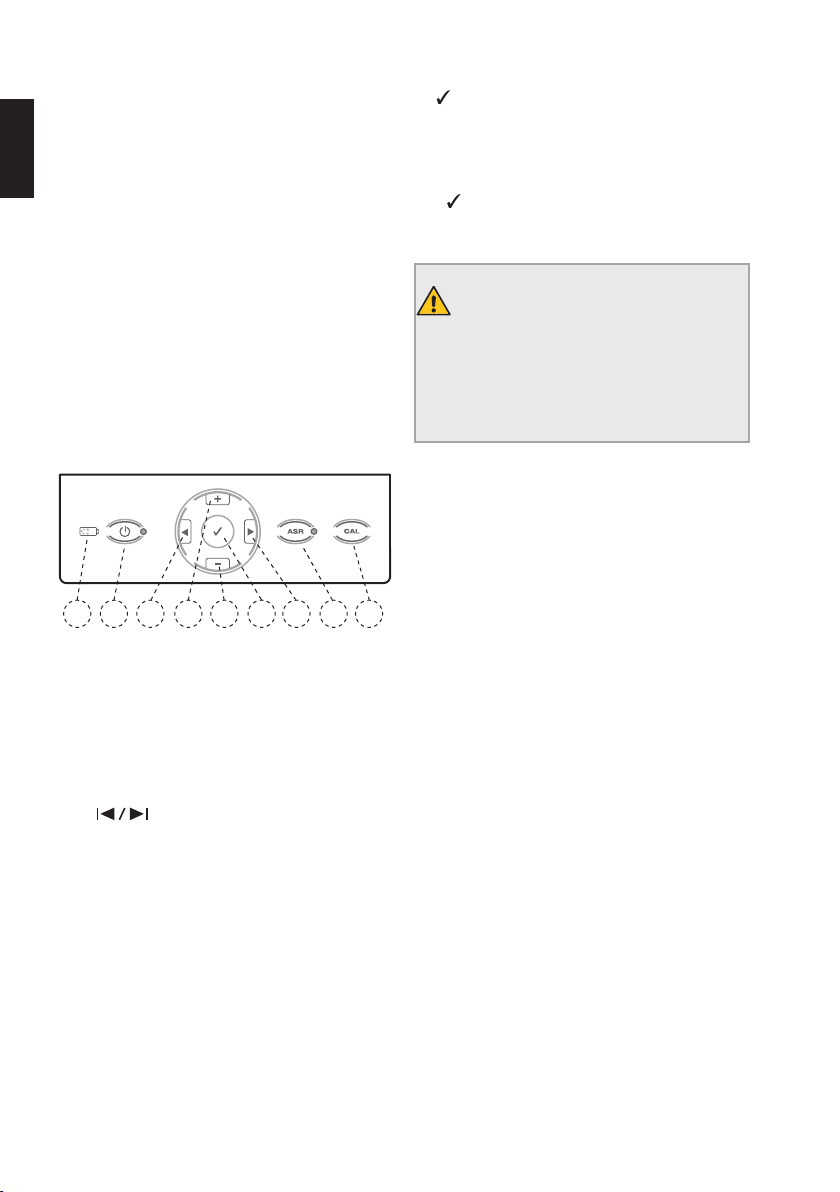
12
Operation and Recharge Times
Recharging the battery after it has been discharged
completely can take up to 3 hours.
en
If the battery has been correctly charged, it should
have an operation time of about 2 hours before
needing to be charged again.
Prolonging Battery Life
In order to ensure long battery life, it is
recommended to always work on battery power
and to only recharge it when it is completely
discharged.
8.3. User Interface
8.3.1. Keypad
1
2
Fig. 5 Keypad
1) ON/OFF
Turns the device on and off.
2) Battery LED Indicator
Indicates the current battery status (see details in
chapter "8.2.5. Battery").
3+4)
Scrolls right/left in the bottom row of the display
through the file system, file, torque and speed
fields. The active field is indicated by an arrow
action (possible only in rotary mode).
5+6) +/–
The + and - keys allow to scroll through the file
systems and files and to individually change the
torque or speed values in all rotary file systems.
3
6
5
4
7
7)
Confirm
Confirms modifications to the torque and speed
settings in each system where modifications are
possible. Also reloads the default parameters when
used together with the ON/OFF key. The CONFIRM
key
may also be used to start the micromotor
without the foot pedal.
8) CAL
WARNING
Do not insert any files during calibration.
Risk of injury, as the micromotor changes
rotational speed from the minimum to the
maximum value during calibration.
Calibrates the VDW 6:1 contra-angle to ensure
torque precision following replacement or
lubrication (see details in chapter "8.4.2. CAL:
Calibration").
9) ASR - Rotary Mode only
Green LED: in rotary mode, auto-stop rotational
direction reversal once the preset torque value has
8
9
been reached.
Red LED: in rotary mode, reversal of rotational
direction without torque limits, controlled by foot
pedal.
LED off: in rotary mode, the micromotor stops once
the preset torque value has been reached.
ASR is deactivated in reciprocating mode (LED off).
Page 49
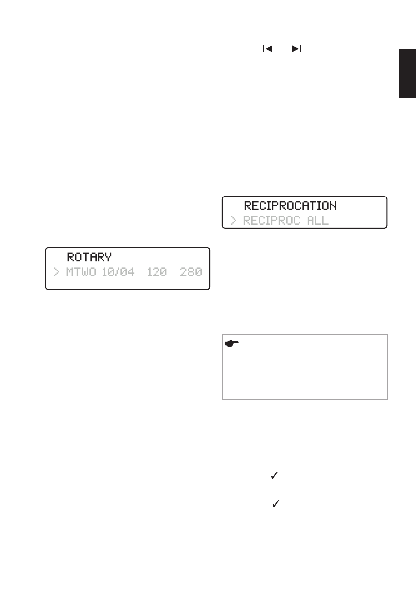
13
8.3.2. Display
When the device is switched on, all LEDs will
light up and a welcome text is displayed. During
following uses, the display will show the last file
system used.
When the device is brought out of standby mode
(by pressing the foot pedal or any key on the
keypad), the display will show the last file system
used before standby mode.
Top row:
Shows which mode is selected - either rotary or
reciprocation mode as indicated by ROTARY or
RECIPROCATION.
Bottom row in rotary mode:
Shows the File System (sys), File (file), Torque
(gcm) and Rotational Speed (rpm) fields:
sys file gcm rpm
sys
Shows the selected file system (e.g. MTWO for
®
Mtwo
, FM for FlexMaster®, DR’s for DR’S CHOICE,
etc.)
file
Shows the selected file.
• Press the
and keys to move to the right
and left (rotary mode only).
• Press the + and - keys to scroll through the file
systems and files and to individually change the
torque or speed values in all rotary file systems.
• Motor settings cannot be changed for
reciprocating systems.
• When torque or speed values are changed
from the default settings, the display will show a
‘-symbol in front of the torque or speed value.
Bottom row in reciprocating mode:
Shows the reciprocating system in use.
Unlike in rotary mode, individual files cannot
be selected in reciprocating mode, as all motor
settings apply to the entire system (indicated by
RECIPROC ALL).
8.3.3. Foot Pedal
NOTES
• For a long life span, do not bend cables.
• In case foot pedal has the tendancy to
slip, clean the rubber feet.
en
gcm
Shows the preset torque limit value
(deactivated in reciprocating mode). Torque is
shown in g/cm (grams-force per centimetre:
1gcm=0.0981Nmm).
rpm
Shows the file rotational speed in rpm (revolutions
per minute) (deactivated in reciprocating mode).
If the standard rotational speed settings have been
changed, a ' will be displayed in front of the new
value.
The micromotor can be started in two different
ways:
• The foot pedal is pressed and the micromotor
operates as long as the foot pedal remains pressed,
• The micromotor is started by pressing the
CONFIRM key
for 1.5 seconds. The micromotor
can be stopped again by pressing any key or the
foot pedal. If the micromotor is started using the
CONFIRM key
, it will automatically shut down
after 5 minutes of inactivity to save power.
Page 50
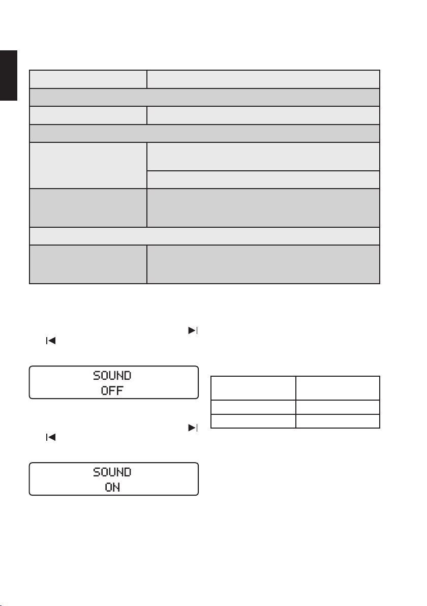
14
8.3.4. Audible Signals
All audible signals are activated upon delivery of the device:
en
Components Audible Signal
Keypad
Keys Confirmation sound when keys on the keypad are pressed.
Motor
Audible signal when torque exceeds approximately 75% of the
Rotary mode
preset value in rotary mode.
Intermittent signal during continuous counter-clockwise rotation.
Reciprocation mode
is affected by an increased stress. See chapter "8.5.4.
Reciprocating Mode" for details.
Battery
Loud warning signal which sounds before the device shuts down
Audible signal when the entire length of the instrument
Battery status
due to low battery power. The battery warning is a HIGH priority
alarm signal.
Deactivating and activating the audible signals
To deactivate the audible signals press the
and
keys simultaneously: a beep will sound
and the following message will be displayed:
To reactivate the audible signals, press the
and
keys simultaneously: a beep will sound
and the following message will be displayed:
8.3.5. File Library
The device contains a file library with the following
preset systems:
Reciprocating Systems:
File System Name Name as displayed on
the device
®
RECIPROC
WaveOne™ WAVEONE ALL
All motor settings apply to the entire system,
indicated by RECIPROC ALL and WAVEONE ALL.
RECIPROC ALL
Page 51
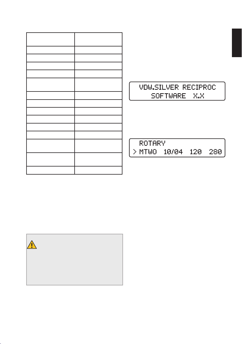
15
Rotary Systems:
File System Name Name as displayed on
the device
VDW.ROTATE VROT
®
Mtwo
FlexMaster
Gates Glidden GATE
Dr’s Choice Individual
Program
TruNatomy™ TN
ProFile
ProGlider
ProTaper
ProTaper
K3™ K3
FlexMaster
Retreatment1
FlexMaster
Retreatment2
Lentulo LENT
®
®
®
®
Universal PTU
®
Next PTN
®
®
MTWO
FM
DR’S
PF
PG
FMR1
FMR2
Before starting the micromotor, pay attention that
the file system indicated on the display corresponds
to the file in use. Refer to the Directions for Use of
the file in use for the proper settings.
The values displayed on the device are precise and
reliable only with a properly maintained VDW 6:1
contra-angle.
8.4. Operation
8.4.1. Power On, Standby Mode, Power Off
Power On
Press the ON/OFF key. All LEDs will light up briefly
as their functionality is tested. A welcome screen
will display the current software version:
In subsequent sessions, the display will show
the first file of the last system used before the
device was switched off or the last file used before
standby mode was activated.
Standby Mode
In order to save battery power, the device
will automatically go into standby mode after
10minutes of inactivity. The display will shut off.
To leave standby mode, press the foot pedal or any
key on the keypad. The device will switch on and
return to the function last in use before it went into
standby mode.
After 30minutes in standby mode, the device will
shut off completely in order to save battery power.
It can be switched on again using the ON/OFF key.
en
WARNING
Follow the instructions given in the
manufacturer’s manual and in the VDW
6:1 contra-angle operating instructions
when using endodontic instruments.
Power Off
Press the ON/OFF key to shut off the device. The
battery LED will no longer be on unless the battery
is recharging.
Page 52
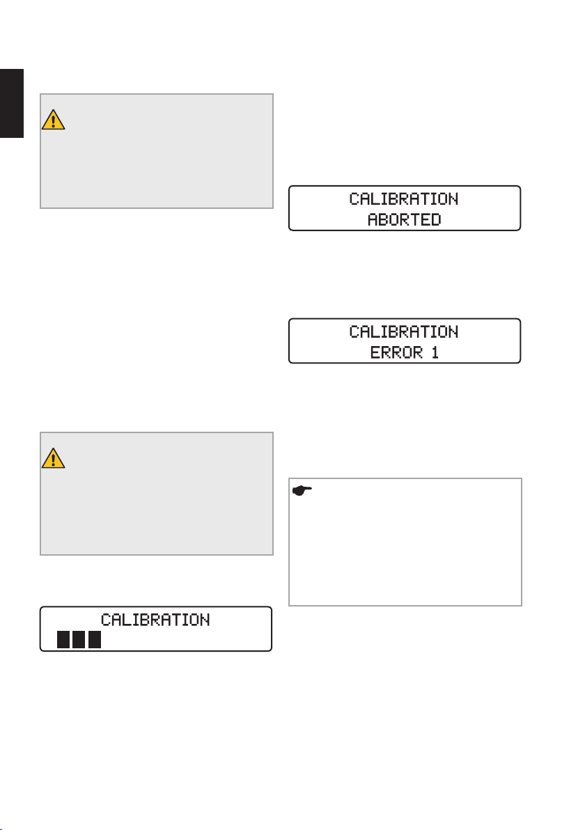
16
8.4.2. CAL: Calibration
en
WARNING
The precision of the working parameters
is ensured only if a properly maintained
VDW 6:1 contra-angle is used.
Calibrating the micromotor automatically sets
the rotational speed in order to ensure torque
precision. Calibration is necessary:
• After replacing the micromotor;
• After replacing and reprocessing the VDW 6:1
contra-angle and at least once a week (refer also
to separate operating instructions for the VDW 6:1
contra-angle).
Starting Calibration
1) Put the VDW 6:1 contra-angle on the
micromotor without any file.
WARNING
Do not insert any files during calibration.
Risk of injury, as the micromotor changes
rotational speed from the minimum to the
maximum value during calibration.
2) Press the CAL key. The calibration process will
begin and the following message will be displayed.
3) The procedure stops automatically as soon as
calibration is complete (all black bars are visible
on the display).
Aborting Calibration
The calibration procedure can be halted at any
time by pressing the foot pedal or any key on the
keypad. The following message will be displayed:
Possible Error Messages
If calibration cannot be correctly performed
or completed, the following message will be
displayed:
Details on possible error messages such as
ERROR 1 or ERROR 2 can be found in chapter
"10.2. Troubleshooting".
8.4.3. ASR: Automatic Stop Reverse
NOTE
ASR function can be activated in rotary
mode only. ASR is active (green LED) in
rotary mode on delivery.
In reciprocating mode, ASR is deactivated
(LED is off).
The micromotor will automatically measure the
inertia of the contra-angle by starting at minimum
rotational speed and accelerating to maximum
speed.
In rotary mode, the ASR function can be changed
by pressing the ASR key. The LED light will change
color depending on the selected function:
Green: When the preset torque is reached, the
micromotor will automatically rotate in the opposite
direction (counter-clockwise). As soon as the file
stops meeting resistance, the micromotor will
automatically begin running forwards (clockwise)
again.
Page 53
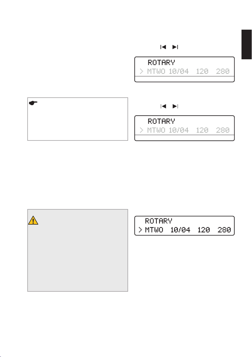
17
Red: The micromotor will automatically rotate
in reverse direction (counter-clockwise) without
torque control.
OFF: In rotary mode, when the preset torque is
reached, the micromotor will stop automatically.
By pressing the foot pedal again, the motor will
start in reverse direction (counter-clockwise).
As soon as the file stops meeting resistance,
the micromotor will automatically begin running
forwards (clockwise) again.
NOTE
ASR functions can be set for each file
in rotary mode. As soon as you select a
different file, the standard setting (green
LED) will be restored.
Audible Signals sound:
• Whenever torque exceeds approximately 75% of
the preset value;
• When the micromotor is running in reverse.
8.5. Selecting File Systems/Files
The display's standard setting is to show the last
file system or corresponding last file used. To make
a new selection:
1) Use the
(arrow):
/ keys to select the sys field
sys file gcm rpm
2) Use the +/- keys to select the desired file
system (scroll up/down).
3) Use the
(arrow):
/ keys to select the file field
sys file gcm rpm
4) Use the +/- keys to select the desired file
(scroll up/down).
5) It is not necessary to confirm the setting. The
desired file or file system is now active.
8.5.1. Rotary Mode
When a file system has been selected in rotary
mode, the first line of the display will read:
en
WARNING
Always check the mode indicated on the
display before use:
- The use of a rotary file in reciprocating
mode may lead to its breakage. Never
use rotary files in reciprocating mode.
- The use of a reciprocating file in rotary
mode may lead to its breakage. Never
use reciprocating files in rotary mode.
The second line will automatically display the first
file in the sequence.
In rotary mode, torque and rotational speed values
can be changed individually for all file systems.
See "8.5.2. Changing Torque and Rotational
Speed (Rotary Mode only)" for a description of this
process.
Page 54
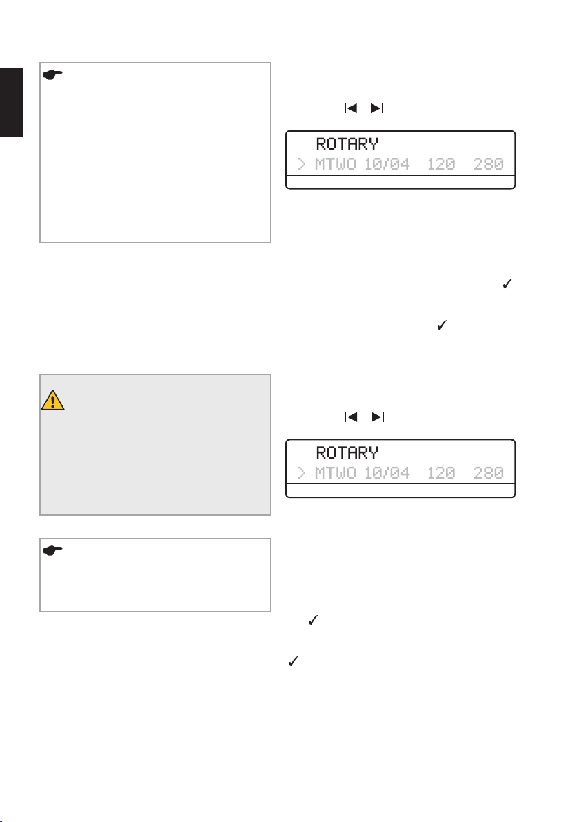
18
NOTES
en
• The ASR function can only be activated
in rotary mode. The ASR function is active
on delivery (green LED). Press the ASR key
to select different functions (see details
in Chapter "8.4.3. ASR: Automatic Stop
Reverse"
• If the rotary file is blocked in the canal,
switch to reverse ASR function (red LED),
restart the motor and pull the file out
carefully.
8.5.2. Changing Torque and Rotational Speed (Rotary Mode only)
In rotary mode, the preset torque and rotational
speed values for all systems can be changed
individually.
WARNING
The settings of torque force and speed in
excess to the recommended values may
lead to file breakage during treatment.
Always refer to the Directions for Use of
the file in use for the proper settings.
Changing Torque:
1) Select the desired rotary file as described
above (arrow indicates active selection).
2) Use the
(arrow):
/ keys to select the gcm field
sys file gcm rpm
3) Use the +/- keys to select the desired torque
(scroll up/down). When the torque value is
changed, it will flash. The available torque settings
range from 20 to 410gcm in steps of 10gcm.
4) After selecting the desired torque, save the
new setting by pressing the CONFIRM key
once. The torque field will stop flashing and will be
marked with a ' symbol. If the setting is not saved
by pressing the CONFIRM key
used and the micromotor will not start.
Changing Rotational Speed:
1) Select the desired rotary file as described
above (arrow indicates active selection).
2) Use the
(arrow):
/ keys to select the rpm field
, it cannot be
sys file gcm rpm
NOTE
Torque and rotational speed cannot be
changed in reciprocating mode.
3) Use the +/- keys to select the desired
rotational speed (scroll up/down). When the
rotational speed value is changed, it will flash. The
available rotational speed values range from 250
to 1000rpm in steps of 10rpm.
4) After selecting the desired rotational speed,
save the new setting by pressing the CONFIRM
key
once. The rotational speed field will stop
flashing and will be marked with a ' symbol. If the
setting is not saved by pressing the CONFIRM key
, it cannot be used and the micromotor will not
start.
Page 55
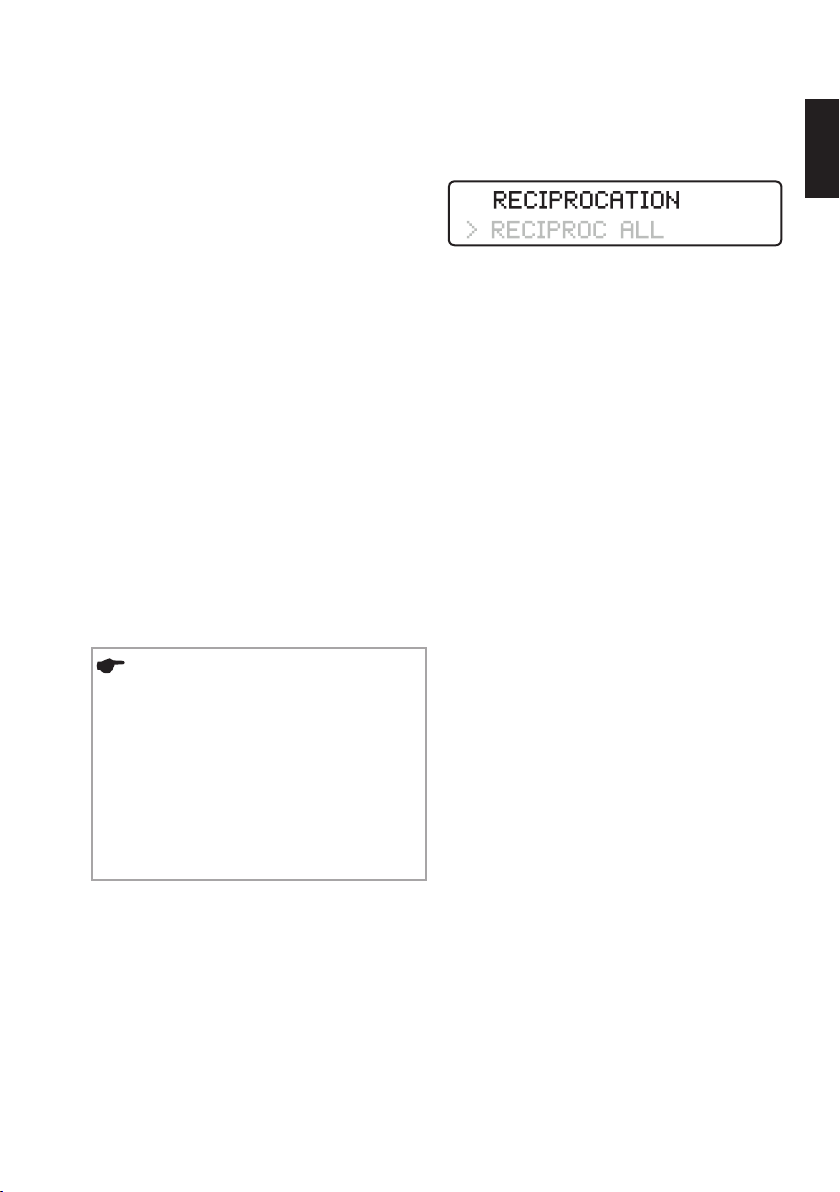
19
8.5.3. Dr's Choice (Rotary Mode only)
You can use the Dr's Choice Individual Program to
create your own file sequence. This enables you to
manage your own series of instruments.
The device is delivered with 15 default values of
torque and rotational speed (for details of the
default values refer to Chapter "15. Dr’s Choice
Tables").
To change these setting, simply “overwrite” them
as described in Chapter "8.5.2. Changing Torque
and Rotational Speed (Rotary Mode only)". Use
the table in Chapter "15. Dr’s Choice Tables" to
record your custom settings. To restore the default
settings, follow the procedure reported in Chapter
"8.6. Default Parameters".
8.5.4. Reciprocating Mode
RECIPROC® and WaveOneTM instruments are
specifically designed to be used in reciprocating
mode, whereby the instrument is driven first in a
cutting direction and then reverses to release the
instrument. The angles of reciprocation are precise
and specific to the design of the instrument.
NOTES
• The RECIPROC
reciprocating files can be distinguished from
rotary files by the following characteristics:
the shaft has a coloured plastic ring and the
cutting edges are inverted.
• The ASR function, which is designed for
rotary mode, is deactivated in reciprocating
mode.
®
and WaveOne™
Working in Reciprocation Mode
When one of the reciprocating files mentioned
above is selected, the first row of the display will
show the following message:
Select the specific reciprocating system RECIPROC
or WAVEONE by selecting the “system” in the
second row of the display via the + and - keys.
Unlike rotary mode, individual files do not have to
be selected in the reciprocating mode, as all motor
settings apply to the entire system, indicated by
RECIPROC ALL.
RECIPROC REVERSE Function
(for VDW RECIPROC
®
Instruments)
This function enables more comfortable work
and uses audible signals to alert the user to the
following events or necessary actions:
• A low, fast beeping sound indicates increased
stress along the entire length of the instrument. It
is therefore necessary to enlarge the canal with
lateral brushing motions. This will reduce the
stress on the instrument.
• A higher, slower beeping sound indicates
an even higher stress on the instrument. The
micromotor will therefore switch automatically to
continuous clockwise rotation in order to release
the instrument. Once the foot pedal has been
released and pressed again, the micromotor will
change back into reciprocating mode. It is now
essential to brush laterally, to enlarge the root
canal.
en
Page 56
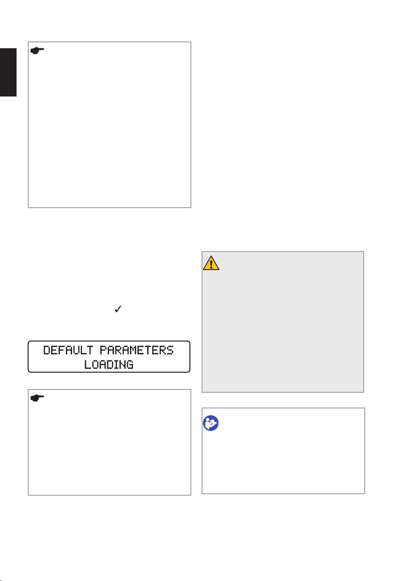
20
NOTES
en
In curved canals, brush away from the
curvature. Before brushing, repeat the
following steps:
• Clean the instrument in the Interim
Stand;
• Irrigate the canal;
• Use an ISO size 10 C-PILOT
check that the canal is not blocked.
• If the reciprocating file is blocked in
the canal, remove the file using a pair of
pliers by pulling it and carefully twisting it
clockwise.
8.6. Default Parameters
To return to the original default parameters, follow
the general reset instructions:
• Make sure that the battery charger is
disconnected from the power outlet.
• Turn off the device.
• Press the CONFIRM key
simultaneously. The device will switch on and the
display will read:
and the ON/OFF key
®
File to
9. Cleaning, Disinfection and Sterilization
Inspect the various cables of battery charger,
micromotor and foot pedal before and after each
use.
Contact the service centre if any of the cable
coatings show signs of wear and tear.
Clean the cables and the outer surfaces of the
device using a paper towel or soft cotton cloth
lightly moistened with an aldehyde-free cleaning
and disinfectant (bacterial and fungicidal) solution,
e.g. Mikrozid AF Liquid or Minuten Spray Classic.
• DENTIRO
Switzerland.
• TopActiv wipes, ad-Arztbedarf GmbH, Germany.
• SprayActiv, ad-Arztbedarf GmbH, Germany.
• DY wipes, DENTSPLY, France.
®
wipes, Oro Clean Chemie AG,
WARNINGS
• To disinfect the equipment and the
cables, wipe the surfaces with a clean
cloth or wipe that has been wetted only
slightly with a non-aggressive disinfectant.
• Do not use any liquids or sprays directly
on the equipment, particularly on the
display.
• Do not use strong alcohol to disinfect
surfaces.
NOTES
• Keep in mind that all individual settings,
including those for the Dr's Choice
Program, will be erased if the default
settings are restored.
• The audible signals are not affected: the
last settings in use before switching off the
device will remain.
CONSULT IFU
VDW 6:1 contra-angle has to be cleaned,
disinfected and sterilized before first
use and after each following use. Refer
to operating instructions for VDW 6:1
contra-angle for the method.
Page 57
21
Ensure that only validated cleaning/disinfection
and sterilization methods are used, that the
devices (disinfector, sterilizer) are maintained and
inspected at regular intervals and that the validated
parameters are preserved throughout every cycle.
In addition, ensure that you always comply with
the applicable statutory rules and regulations
regarding hygiene in your practice or clinic. This
applies also to the guidelines about effective prion
inactivation.
For your own safety, always wear gloves, protective
eyewear and a surgical mask when handling
contaminated accessory parts.
WARNINGS
• The cables cannot undergo thermal
disinfection, nor thermal sterilization.
• Using substances other than those
described above can cause damage to the
device and the accessory parts.
• Do not use hot-air or radiation
sterilization, and do not sterilize using
formaldehyde, ethylene oxide or plasma.
• The plastic casing is not sealed. Do not
use any liquids or sprays directly on the
console, especially on the display or near
the electrical sockets.
We accept no liability in the event that these
instructions are disregarded or processes that
have not been validated are used to prepare the
accessories for reuse.
WARNING
The components are not delivered neither
sterile nor disinfected. The following
steps must be performed before first use
and after each following use.
9.1. Pre-Treatment (to be performed after each use)
Pulp and dentine residues must be removed from
the accessory parts immediately; if necessary, use
a brush to carefully clean the products (no later
than 2 hours after use). Do not allow remnants to
dry on. After using the accessories on the patient,
place them directly into a dish filled with a suitable
cleaning and disinfection solution (e.g. CYDEZIME
®
ENZOL
Enzymatic Detergent Solution, Johnson &
Johnson Medical, 0,8% for between 1 minute and
2 hours) for cleaning, pre-disinfection and interim
storage. Make sure that the products are fully
immersed.
Afterwards, wash the accessories under running
sterile, deionized water or in a disinfection solution
at least three times for one minute each time, in
order to remove all visible traces of contamination
and remnants. Use an aldehyde-free disinfectant
(aldehyde sets blood stains), tested for
effectiveness (e.g. VAH/DGHM or FDA-approved
or CE certified), appropriate for disinfecting the
accessories and compatible with the accessory
parts (see chapter "9.7. Material Durability").
Use only clean, soft brushes to manually remove
contamination and remnants, or a clean, soft cloth
or wipe that is used only for this purpose. Do not
use metal brushes or wire wool. Check that no
visible contamination or remnants are left. Repeat
the pre-cleaning process if necessary.
Please, note that the disinfectant used for pretreatment is only for personal protection and dœs
not obviate the need for disinfection once cleaning
has been completed. Pre-treatment must not be
omitted.
WARNING
Do not use any automatic processes or
ultrasonic baths to clean or disinfect the
accessories.
®
,
en
Page 58

22
9.2. Manual Cleaning and Disinfection
When selecting cleaning and disinfectant solutions,
en
make sure that:
• They are intended for use in cleaning or
disinfecting instruments.
• The disinfectant’s effectiveness has been tested
(e.g. VAH/DGHM or FDA-approved or CE certified)
and that it is compatible with the cleaning solution.
• The chemicals used are compatible with the
accessory parts (see chapter "9.7. Material
Durability").
Combined cleaning/disinfectant solutions can
be used if the instruments are only slightly
contaminated (no visible contamination).
Follow the instructions provided by the manufacture
of the cleaning and disinfectant solutions regarding
concentration, application time and rinsing.
Use only freshly-prepared solutions made with
water which is either sterile or contains only low
levels of bacteria (< 10 cfu/ml) and endotoxins
(<0.25EU/ml, e.g. purified water (PW/HPW)), as
well as filtered, oil-free air for drying.
Make sure that the accessories are not in direct
contact with one another.
Step-by-Step Procedure
Cleaning
1) Place the pre-cleaned accessory parts in the
cleaning bath for the stipulated application time
(e.g. CIDEZYME
Solutions, Johnson & Johnson Medical, 0.8% for
1 minute); ensure that they are covered sufficiently
(if necessary, use a soft brush to carefully brush
them off).
2) Take the instruments out of the cleaning bath
and rinse them thoroughly with sterile, deionized
water at least three times for one minute each
time.
®
, ENZOL® Enzymatic Detergent
Disinfection
3) After cleaning and inspecting the accessory
parts, place them in the disinfection bath for the
prescribed contact time (E.G. Cidex OPA, Johnson
& Johnson Medical, 100% for 20 minutes). The
accessories must be sufficiently immersed in the
solution.
4) Then take the instruments out of the
disinfection bath and rinse them thoroughly with
water at least five times for one minute each.
5) Dry all accessories by blowing them down
fully with oil-free, filtered compressed air and then
leave them to dry further in a clean place for at
least 20 minutes. Once the accessories are dry,
inspect and pack them as soon as possible (see
section entitled "9.3. Inspection/Maintenance"
and "9.4. Packing").
6) The contra-angle has to be lubricated after
cleaning and disinfection, but before sterilization.
Follow the instructions given in the separate
operating instruction of the VDW 6:1 contra-angle
as well as the following notes:
• When lubricating the contra-angle, make sure no
lubricant penetrates the micromotor.
• If the contra-angle is being lubricated manually,
use pressurized air to remove excess lubricant
(blow for about 5 sec.) before reapplying the
contra-angle back onto the micromotor. Calibrate
the contra-angle after lubrication.
• If the contra-angle is being lubricated
automatically using a maintenance or lubrication
device, follow the device manufacturer’s
instructions carefully and make sure no excess
lubricant remains in the contra-angle.
• Do not lubricate the micromotor under any
circumstances. Lubricant can affect micromotor
functioning.
Page 59
23
9.3. Inspection/Maintenance
Check all accessory parts after cleaning or
cleaning/disinfection. Dispose of defective
accessory parts immediately. Defects may include:
• Deformation of the plastic.
• Corrosion.
• Discoloration of the plastic.
Accessory parts which are still contaminated must
be cleaned and disinfected again. Maintenance is
not required. Do not use instrument lubricant.
9.4. Packing
Pack the accessory parts in disposable sterilization
packaging (individual single-use packaging),
which meets the following requirements:
• In compliance with ISO 11607-1.
• Suitable for steam sterilization (temperature-safe
to 142°C (288°F), sufficiently steam-permeable).
9.5. Sterilization
Use only the sterilization methods given below;
other sterilization procedures are not allowed.
• Steam sterilization.
• Fractional vacuum/pre-vacuum procedures
(at least three vacuum cycles) or gravity method
with sufficient product drying (product must be
sufficiently dry). The drying time that is required
depends directly on parameters that are the sole
responsibility of the user (loading configuration,
how many items are loaded and how closely
together, condition of the sterilizer, etc.), and must
therefore be established by the user. However, the
drying time must never be less than 20 minutes.
The gravity method is less effective and must only
be used if it is not possible to use the fractionated
vacuum method.
• Steam sterilizers in compliance with EN13060
or EN285, ANSI/AAMIST79.
• Sterilization validation must be done in
accordance with ISO 17665-1 (valid installation
and operation qualification (IQ and OQ) as well as
product specific performance qualifications (PQ)).
• Maximum sterilization temperature 135°C
(275°F); plus tolerance as specified in
ISO17665-1.
• Sterilization time (application time at sterilization
temperature) at least 3 minutes at 134°C (273°F).
en
WARNINGS
• Only the VDW 6:1 contra-angle is
suitable for thermal sterilization. See
the separate operating instructions on
sterilization procedure of VDW 6:1 contraangle for its proper reprocessing.
• Do not apply thermal procedures to
any other VDW.SILVER
components other than the VDW 6:1
contra-angle.
• Never put the micromotor or other
accessory parts in the Washer-Disinfector
or in an autoclave or in a ultrasonic bath.
®
RECIPROC®
WARNINGS
• Rapid-sterilization processes and
sterilization processed with unpackaged
accessory parts are not permitted.
• Do not use hot-air sterilization, radiation
sterilization or sterilization involving
formaldehyde, ethylene oxide or plasma.
• Additionally, regional requirements have
to be followed.
Page 60
24
9.6. Storage
After sterilization, the instruments must be stored
dry and dust-free in the sterilization packaging.
en
9.7. Material Durability
When selecting cleaning and disinfection products,
make sure that they do not contain any of the
following substances:
• Phenol.
• Strong acids (pH < 6) or strong alkalis (pH > 8).
• Aldehydes.
• Anti-corrosive substances (especially di- or
triethanolamine).
• Oxidants (hydrogen peroxide, sodium
hypochlorite over 5% strength).
• Solvents.
10. Maintenance and Troubleshooting
10.1. Maintenance
For optimal battery performance, the battery
should be replaced every 2 years by an authorized
service centre.
NOTE
In order to ensure good battery life, it is
recommended to always work on battery
power and to recharge it only when it is
completely discharged.
Follow the instruction provided in Chapter 9
“Cleaning disinfection and sterilization” to
ensure that the device is functioning according to
specifications.
10.2. Troubleshooting
If the device is not functioning properly, consult
the following table for information on the possible
causes and solutions.
The following information are valid only if you are
using the VDW.SILVER
with the compatible accessories and/or spare
parts.
WARNING
Disconnect the device when it is not
functioning correctly to prevent any injury
to the user or patient.
®
RECIPROC® in combination
WARNING
Do not open the device in any case. No
serviceable parts inside.
Should the information in the table not solve
the problem, contact the service centre or the
VDW GmbH Sales Service. Service and repair
work can be done only by factory-trained service
personnel.
Page 61
25
Problem Cause Action
Smoke or fire from the
Hardware fault.
device.
Stop using your device immediately, disconnect
it from the mains plug and contact the service
centre.
Battery charger housing
Hardware fault.
damaged/Broken
Stop using your device immediately, disconnect
it from the mains plug and contact the service
centre.
Handpiece too hot you
Hardware fault.
cannot keep in hand.
Stop using your device immediately, disconnect
it from the mains plug and contact the service
centre.
Liquid leakage from the
Battery case fault.
device (electrolyte leakage
from the battery)
Stop using your device immediately, disconnect
it from the mains plug and contact the service
centre.
The device dœs not switch
on.
• Battery empty.
• Battery charger not
properly connected
• Recharge the battery.
• Check battery charger connection to the
power socket.
to the power socket.
• Battery charger
defective.
The device is not working
as expected.
Corrupted
configuration
Reset to Default Parameters as described in
Chapter "8.6. Default Parameters".
memory.
The display is
malfunctioning: shaded,
flickering or totally blank
Strong electrostatic
discharge.
Stop using the device immediately, disconnect it
from the mains and wait 5 minutes.
Reconnect the device to the mains and restart it.
If the problem persists, disconnect the device
from the mains and contact the service centre.
Risk of fire and electric shock.
Risk of fire and electric shock.
Risk of fire and electric shock.
Risk of fire and electric shock.
Risk of allergic reaction or toxicity.
en
Page 62
26
The micromotor dœs not
start.
en
The foot pedal dœs not start
the micromotor.
• Micromotor
cable not properly
connected.
• Defective VDW6:1
contra-angle.
• Defective
Micromotor.
• Strong
electrostatic
discharge
• Foot pedal not
properly connected.
• Faulty foot pedal.
• Check whether the micromotor cable is
correctly connected to the micromotor housing
and to the console.
• Check that the contra angle is working
correctly or that it is not stuck: remove the
contra-angle from the micromotor, connect a file
to the contra-angle and rotate the file manually.
If the file rotates without significant
friction, the contra-angle should be working
properly and proceed with the troubleshooting
to identify the root cause of the problem.
Otherwise, replace the contra-angle.
• Check that the micromotor is working
properly: calibrate without the contra-angle.
If the calibration fails, set the maximum
rotational speed on the console, start the
micromotor, and keep it running for at least
5 minutes. Repeat the calibration. If the
calibration fails again, contact the service
centre.
If the calibrations is successful, put the
contra-angle back on the micromotor and
repeat the calibration process. If the calibration
fails again, contact the service centre.
• It is known that a strong ESD may lead to a
temporary motor fault. If the above listed actions
failed to fix the motor problem, proceed with the
troubleshooting instruction provided for the case
"the display is malfunctioning".
• Check that the foot pedal is correctly
connected to the device and start again by
pressing the foot pedal.
If the micromotor dœs not start, start it by
pressing the CONFIRM key
for 1.5seconds.
If this starts the micromotor, replace the foot
pedal. Otherwise, contact the service centre.
Page 63
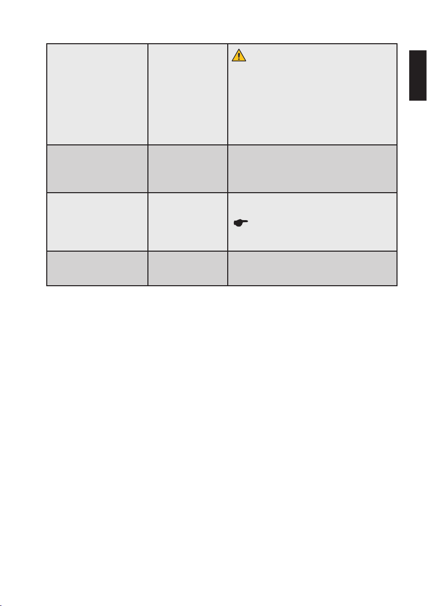
27
Battery charger not working
properly.
The battery discharges too
quickly.
Battery charger
faulty.
• Battery not
properly charged.
• Defective battery
or battery charger.
CALIBRATION ERROR 1. Micromotor not
properly connected.
CALIBRATION ERROR 2. Defective VDW6:1
contra-angle with
excessive resistance.
How to contact the service centre:
VDW GmbH
Sales Service
Hoferstr. 1
81737 Munich
Germany
Phone: +49 89 62734555
Fax: +49 89 62734374
[email protected]
www. vdw-dental.com/service
Do not replace the provided battery charger
with any other kind of power supplies.
• Check that the plug is properly connected to
the battery charger housing.
• Check that the battery charger is properly
connected to the power outlet and to the
console.
• Contact the service centre to have it replaced.
• Fully charge the battery, by paying attention
to the battery LED. Refer to Chapter "8.2.5.
Battery".
• Contact the service centre to have it replaced.
Check whether the micromotor is correctly
connected and retry calibration.
If this dœs not solve the issue, follow
troubleshooting instructions for case “The
micromotor dœs not start”.
Follow troubleshooting instructions for case
“The micromotor dœs not start”.
en
Page 64

28
11. Adverse Event Notification
If any incident occurs that is directly or indirectly
en
related to the device, report it immediately to the
manufacturer and to the competent authority
of your country and of where the patient is
established (if different).
By email:
MunichDEU-VDW-ComplaintDepartment@vdwdental.com / [email protected]
By fax:
+49 89 62734 - 379
By post:
VDW GmbH
Complaint Department
Bayerwaldstr. 15
81737 Munich
Germany
12. Disposal of Waste Parts
The device must not be discarded in domestic
household waste. Should you wish to definitively
dispose of the device, comply with the national
regulations that apply to your country for the
disposal of electric equipment. For further details,
contact VDWGmbH directly.
NOTES
For information on the proper disposal of
the endodontic instruments, refer to the
manufacturer’s instructions.
Before disposal, the device and its accessories
must not be contaminated and must have been
completely reprocessed, following the instructions
provided in Chapter 9 “Cleaning, Disinfection and
Sterilization”.
Waste Electrical and Electronic Equipment
belonging to customers located in the European
Union may be shipped to VDW for recycling in
accordance to WEEE regulations. The costs of
recycling, excluding shipping fees, are covered by
VDW.
Page 65

29
13. Warranty
In addition to the warranty applicable under
the sales contract with the dental dealer, VDW
directly offers customers the following service
warranty:
1) VDW guarantees proper manufacturing of
the product, the use of top quality materials, all
required tests and adherence to all applicable
pertinent laws and regulations relating to the
product.
The full functionality of VDW.SILVER
is covered by a 36 month warranty (exception:
contra-angle is covered by a 12 month warranty),
beginning on the date of delivery to the customer
(according to the shipping papers with the
respective product serial number, issued by the
seller at the time of purchase).
The customer is only entitled to warranty services
within the warranty period and under the condition
that VDW has been informed of the defect in
writing within a two month period from the date of
discovery of the defect.
2) In the event of a warranty claim, the VDW
Service Centre in Munich, Germany will handle any
repairs within 3 business days from receipt at the
VDW facility in Munich plus transport time to return
the shipment to the customer.
3) This warranty covers only the exchange or
repair of individual components or parts affected
by manufacturing defects. The cost for personnel
to be dispatched for purposes of technical
assistance from the dealer to the customer, and/
or packaging expenses of the customer will not
be covered by VDW. Any customer claims beyond
the realm of repair, such as claims for damages,
will not be covered. This warranty dœs not include
any compensation for direct or indirect personal
injuries or material damage of any kind. The
customer will not be entitled to damages for downtime of the equipment.
®
RECIPROC®
4) The warranty dœs not extend to damage for
which evidence can be provided by VDW that such
damage has been caused by negligence on the
part of the user as related to regular maintenance
(see operating instructions), particularly during
loading, unloading and maintenance of the battery
unit in accordance with the user instructions,
as well as regular careful maintenance of
the contra angle in compliance with the
separate user instructions for this component.
The warranty explicitly excludes any defects
arising on the basis of:
• damage occurring during transport to VDW for
the purposes of repair,
• damage occurring through atmospheric events
such as lightning strikes, fire and/or humidity.
This warranty shall automatically become invalid if
the product has been improperly repaired, modified
or manipulated in any manner by the user, by nonauthorized persons or by third party personnel.
5) This warranty is valid only if the device sent for
repair includes the invoice with confirmation of the
product’s shipping date.
6) Legal claims, such as through product liability
law or claims against sources from whom the
customer has purchased the product, in particular
the dental dealer, remain unaffected.
en
Page 66
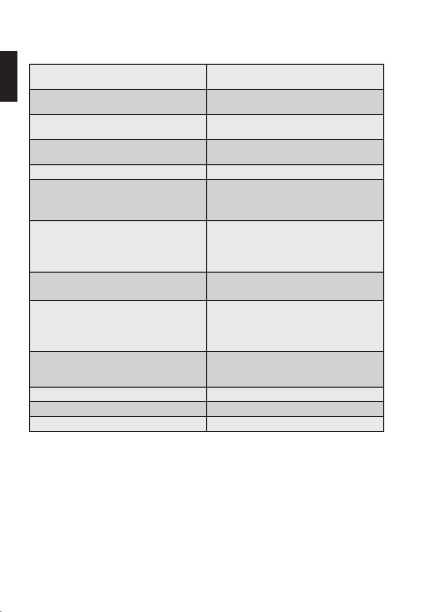
30
14. Technical Data
MANUFACTURER VDW GmbH, Bayerwaldstr. 15
en
MODEL VDW.SILVER
MEDICAL PRODUCT CLASSIFICATION Class IIa, according to Appendix IX, Rule IX,
ELECTRICAL PROTECTION CLASS Electrical Insulation Class-II according to
APPLIED PART BF (contra-angle)
IP GRADE Console: IP20
DIMENSIONS Console: 209 x 89 x 93mm
MATERIALS Console housing: PC/ABS
WEIGHT Console, cables, micromotor and contra-angle:
CONTRA-ANGLE Compatible with endodontic files having 2.334
INTERNAL BATTERY NiMH Battery, 2000mAh, 6Vdc
BATTERY CHARGER/MAINS POWER SUPPLY 100-240Vac, 47-63Hz, 0.8A max
CONSOLE POWER REQUIREMENTS 12Vdc, 2.5A max
81737 Munich, Germany
®
REF V04 1163 000 000
93/42/EEC and Amd 2007/47/EEC
IEC60601-1
Micromotor: IP24
Foot pedal: IPX1
Micromotor: 90.5mm, Ø 23.5mm with cable
1.8m long
Foot pedal: Ø 10cm with cable 1.8m long
Micromotor: Aluminium
1.1kg
Battery charger: 0.237kg
Foot pedal: 0.113kg
- 2.35mm shank diameter, shaft type 1 as per
ISO1797:2017
RECIPROC® –
Page 67
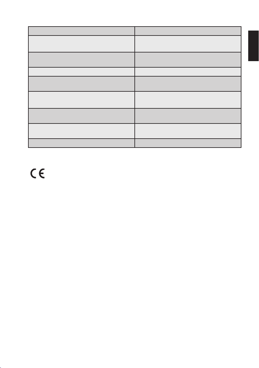
31
0123
OUTPUT POWER TO THE MICROMOTOR 30W max
OPERATIONAL MODE Non-continuous mode
Duty Cycle: 3min ON/1min OFF
TORQUE RANGE 20-410gcm (≈ 0.2-4.1Ncm); ± 20% in rotary
ROTATIONAL SPEED IN MICROMOTOR SHAFT 1500-6000rpm (±10%) in rotary mode
SECURITY LEVEL NEAR FLAMMABLE
ANÆSTHETIC GAS, MIXTURES OR OXIGEN
NORMAL OPERATING CONDITIONS +15°C/+35°C; RH<80% (non condensing);
mode
Not suitable for use near flammable anesthetic,
gas mixtures or oxygen
atmospheric pressure:80 - 106kPa
en
TRANSPORT AND STORAGE CONDITIONS -20°C/ +50°C; RH:20-90%;
ESSENTIAL PERFORMANCE No Essential Performance (according to
SERVICE LIFE Console, micromotor, contra-angle: 3years
This product bears CE marking in accordance with the provisions of Council Directive
93/42/EEC of June 14, 1993 concerning medical device.
This product first received the CE marking in 2010
atmospheric pressure: 50 - 106kPa
MDD93/42/EEC and Amd.2007/42/EEC)
Page 68
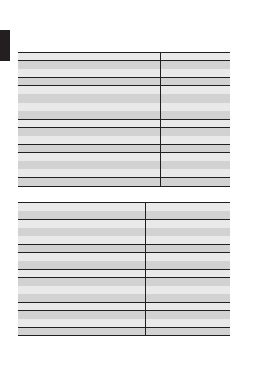
32
15. Dr’s Choice Tables
Record the file type and the selected values of your custom torque and rotational speed settings in the
en
following table (for details, see chapter "8.5.3. Dr's Choice (Rotary Mode only)"):
File Position File Type gcm rpm
01
02
03
04
05
06
07
08
09
10
11
12
13
14
15
Dr´s Choice default settings:
File Position gcm rpm
01 30 300
02 50 300
03 70 300
04 100 300
05 120 300
06 150 300
07 170 300
08 200 300
09 220 300
10 250 300
11 270 300
12 300 300
13 320 300
14 350 300
15 400 300
To restore default parameters, see chapter "8.6. Default Parameters".
Page 69
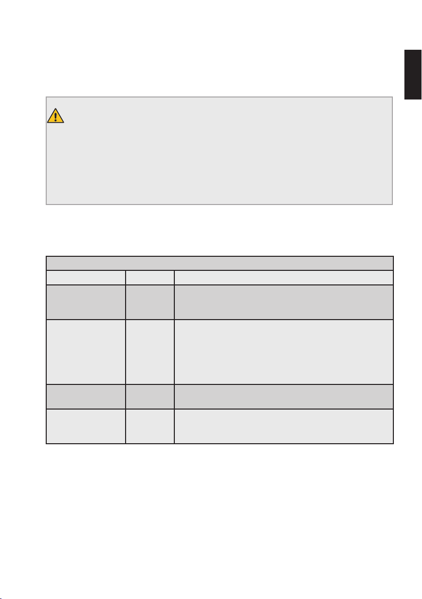
33
Electromagnetic Emissions and Immunity
The device complies with all the requirements foreseen by the IEC60601-1-2:2014 (4th Edition) and by
the previous edition: IEC60601-1-2:2007 (3
WARNING
• The use of parts other than those supplied or listed as accessory may negatively affect EMC
performance.
• Portable RF communications equipment (including peripherals such as antenna cables and
external antennas) should be used no closer than 30cm (12inches) to any part of the device,
including cables. Otherwise, degradation of the performance of this equipment could result.
The device is intended for use in the environments specified in Chapter 3 and Basic Safety is maintained
in the electromagnetic environment specified below.
Electromagnetic emissions compliance
Emission test Conformity Electromagnetic environment - guidance
RF Emissions
Cispr11
RF Emissions
Cispr11
Harmonic emissions
IEC61000-3-2
Voltage fluctuations/
flicker emissions
IEC61000-3-3
Group 1
Class A
Class A
Conforms
Conforms
rd
Edition).
The device uses RF energy only for its internal function.
Therefore, its RF emissions are very low and are not likely to
cause any interference in nearby electronic equipment.
The emissions characteristics of this equipment make it suitable
for use in professional healthcare facilities and hospitals. If it
is used in a residential environment, this equipment might not
offer adequate protection to radio-frequency communication
services. The user might need to take mitigation measures,
such as relocating or re-orienting the equipment.
en
Page 70

en
Electrostatic
discharge (ESD)
IEC61000-4-2
Electrostatic fast
transient/burst
IEC61000-4-4
Surge
IEC61000-4-5
Voltage dips
IEC61000-4-11
Voltage
interruptions
IEC61000-4-11
Power frequency
magnetic field
IEC61000-4-8
Conducted RF
IEC61000-4-6
Immunity test
34
Electromagnetic immunity compliance
IEC60601-1-2
test level
Compliance level
±8kV contact
±15kV air
±1kV for I/O lines 100kHz repetition
±2kV for power supply lines 100kHz
repetition frequency
±1kV line-to-line
(±2kV line-to ground; case not applicable to
electrically insulated Class II ME Equipment)
0% U
for 0.5cycles at 0°, 45°, 90°, 135°,
T
180°, 225°, 270° and 315°
0% U
for 1cycle and 70% UT for 25/30cycles.
T
Single phase at 0°
0% U
for 250/300cycles
T
30A/m (50Hz or 60Hz)
3Vrms (0.15MHz - 80MHz)
6Vrms in ISM bands
80% AM at 1kHz
Electromagnetic environment
- guidance
Floors should be wood,
concrete or ceramic tile.
If floors are covered with
synthetic material, the relative
humidity should be at least
30%.
The medical device is suitable
for use in professional
healthcare establishment
environments.
The medical device is suitable
for use in professional
healthcare establishment
environments. If the user
of the device requires
continued operation during
power mains interruptions,
it is recommended that the
device is powered from an
uninterruptible power supply
or a battery.
The medical device is suitable
for use in professional
healthcare establishment
environments.
Portable RF communications
equipment (including
peripherals such as antenna
cables and external antennas)
should be used no closer than
30cm (12inches) to any part of
the product, including cables.
Otherwise, degradation of the
performance of this equipment
could result.
Page 71
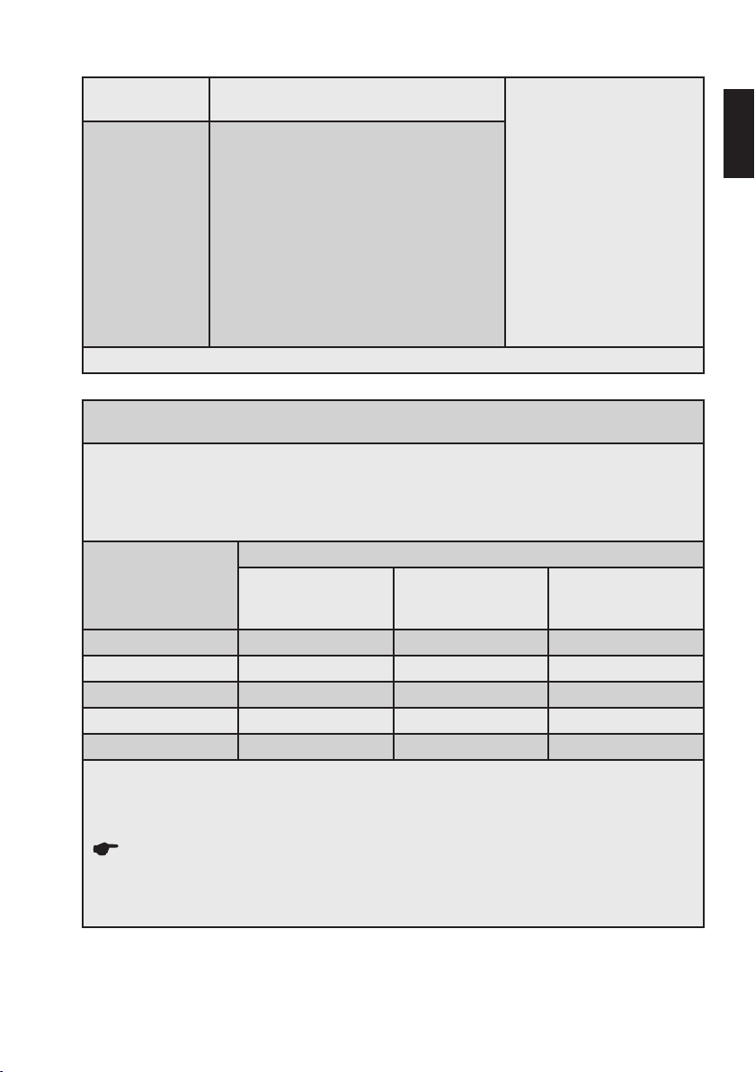
35
Radiated RF
IEC61000-4-3
Proximity fields
from RF wireless
communications
equipment
IEC61000-4-3
3V/m 80MHz - 2.7GHz
80% AM at 1kHz
9V/m
710MHz, 745MHz, 780MHz, 5.240MHz,
5.550MHz, 5.785MHz
27V/m
385MHz
28V/m
450MHz, 810MHz, 870MHz, 930MHz,
Portable RF communications
equipment (including
peripherals such as antenna
cables and external antennas)
should be used no closer than
30cm (12inches) to any part of
the product, including cables.
Otherwise, degradation of the
performance of this equipment
could result.
1.720MHz, 1.845MHz, 1.970MHz,
2.450MHz
Note: U
is the mains voltage in AC before applying test level.
T
Recommended Minimum Separation Distances between Portable and Mobile RF Communications
Equipment and the Device as per IEC60601-1-2 Ed. 3
The device is intended for use in an electromagnetic environment in which radiated RF disturbances
are controlled. The customer or the user of the device can help prevent electromagnetic interference
by maintaining a minimum distance between portable and mobile RF communications equipment
(transmitters) and the device as recommended below, according to the maximum output power of the
communication equipment.
Rated maximum
output power of
transmitter (W)
Separation distance according to frequency of the transmitter (m)
From 150kHz to
80MHz
d = 1.2*√P
From 80MHz to
800MHz
d = 1.2*√P
From 800MHz to
2GHz
d = 1.2*√P
0.01 0.12 0.12 0.23
0.1 0.38 0.38 0.73
1 1.2 1.2 2.3
10 3.8 3.8 7.3
100 12 12 23
For transmitter rated at a maximum output power not listed above, the recommended separation
distance d in meters (m) can be determined using the equation applicable to the frequency of the
transmitter, where P is the maximum output power rating of the transmitter in watts (W) according to
the transmitter manufacturer.
NOTES
• At 80MHz and 800MHz, the separation distance for the higher frequency range applies.
• These guidelines may not apply in all situations. Electromagnetic propagation is affected by
absorption and reflection from structures, objects and people.
en
Page 72

0123
VDW GmbH
Bayerwaldstr. 15
81737 Munich
Germany
Tel +49 (0) 89 62734-0
Fax +49 (0) 89 62734-304
[email protected]
MENSILVERDFUWEB Vol.1 Rev.8 / 10.05.2019
Page 73
VDW.SILVER
RECIPROC
®
®
Mode
d’emploi
vdw-dental.com
Page 74

Nous vous remercions d'avoir choisi le
moteur d’endodontie VDW.SILVER®RECIPROC®.
fr
Les produits endodontiques, ainsi que les prestations
associées, sont au cœur de l’activité de VDWGmbH.
Grâce à une coopération étroite et constante avec les
universités et les endodontistes du monde entier, nous
sommes en mesure de développer des concepts, des
produits et des systèmes innovants pour simplifier le travail du dentiste et améliorer son efficacité.
En choisissant le moteur d’endodontie
VDW.SILVER
®
RECIPROC®, vous avez fait l’acquisition
d’un produit développé et testé rigoureusement qui
répond aux exigences les plus strictes en termes de
fonctionnalités et d’utilisation.
Ce mode d’emploi est disponible dans d’autres langues
sur demande.
Le présent document a été rédigé avec le plus grand
soin, mais malgré toute notre attention, des erreurs ont
pu s’y glisser. Toute suggestion concernant l‘amélioration
de ce document est bienvenue.
Dans ce cas, veuillez contacter directement VDWGmbH.
2
VDW GmbH
Bayerwaldstr. 15
81737 Munich
Allemagne
Tél. +49 89 62734-0
Fax +49 89 62734-304
[email protected]
www.vdw-dental.com
Page 75

Table des matières
3
1. Avant l’utilisation ............................................4
2. Identification des pictogrammes ...................5
2.1. Pictogrammes utilisés dans ce mode
d’emploi ...........................................................5
2.2. Pictogrammes apposés sur l’emballage, le
dispositif et ses composants ...........................5
3. Usage prévu, utilisateur concerné et
population de patients ....................................6
4. Contre-indications ..........................................6
5. Mises en garde ...............................................6
6. Précautions .....................................................7
7. Effets secondaires ..........................................7
8. Mise en service (étape par étape) ..................7
8.1. Composants et accessoires fournis .................8
8.2. Mise en route ...................................................9
8.2.1. Préparation .......................................................9
8.2.2. Vue des connectiques .......................................9
8.2.3. Chargeur de batterie ....................................... 10
8.2.4. Micromoteur, contre-angle VDW6:1 et
pédale ............................................................11
8.2.5. Batterie ...........................................................11
8.3. Interface utilisateur .......................................12
8.3.1. Clavier ............................................................12
8.3.2. Écran ..............................................................13
8.3.3. Pédale ............................................................13
8.3.4. Signaux sonores .............................................14
8.3.5. Bibliothèque de limes ...................................... 14
8.4. Fonctionnement .............................................15
8.4.1. Mise en marche, mode veille et arrêt ..............15
8.4.2. CAL: calibrage ................................................16
8.4.3. ASR: Automatic Stop Reverse .........................16
8.5. Sélection d’un système de limes/ de limes ..17
8.5.1. Mode de rotation continue ..............................17
8.5.2. Modification du couple et de la vitesse de
rotation (mode de rotation continue
uniquement) ...................................................18
8.5.3. Dr’s Choice (mode de rotation continue
uniquement) ...................................................19
8.5.4. Mode réciproque ............................................. 19
8.6. Paramètres par défaut ...................................20
9. Nettoyage, désinfection et stérilisation .......20
9.1. Prétraitement (à réaliser après chaque
utilisation) ......................................................21
9.2. Nettoyage et désinfection manuels ...............22
9.3. Contrôle/Entretien ..........................................23
9.4. Emballage ......................................................23
9.5. Stérilisation ....................................................23
9.6. Stockage ........................................................24
9.7. Résistance des matériaux .............................24
10. Entretien et dépannage ................................24
10.1. Entretien ........................................................24
10.2. Dépannage .....................................................24
11. Notification d’un événement imprévu ..........28
12. Mise au rebut des pièces usagées ...............28
13. Garantie .........................................................29
14. Caractéristiques techniques ........................30
15. Tableaux pour le programme Dr´s Choice ....32
Émissions et immunité
électromagnétiques ......................................33
fr
Page 76
4
1. Avant l’utilisation
Les informations fournies dans le présent document sont importantes pour une utilisation du
fr
VDW.SILVER®RECIPROC® en toute sécurité, sans risquer
de blesser l’utilisateur ou le patient.
Veuillez lire attentivement l’intégralité des instructions à
respecter avant, pendant et après l’utilisation du dispositif.
Le présent document n’inclut pas le protocole d’utilisation
du contre-angle VDW6:1 ni celui des limes endodontiques.
Veuillez également lire attentivement ces documents afin
de disposer de toutes les informations concernant les
dispositifs utilisés en association avec le
VDW.SILVER
Veuillez conserver ce manuel ainsi que les autres documents susmentionnés à portée de main pour pouvoir
vous y référer à tout moment. Veuillez conserver l’emballage d’origine –celui-ci pourra servir pour l’expédition ou
le stockage du dispositif.
®
RECIPROC®.
MISES EN GARDE
• Il est interdit d’utiliser des accessoires autres
que ceux indiqués, à l’exception des composants vendus par le fabricant comme pièces
de rechange. Utilisez uniquement des accessoires et pièces de rechange d’origine. L’utilisation de câbles et d’accessoires autres que
ceux spécifiés peut perturber la compatibilité
électromagnétique du dispositif.
• N’OUVREZ PAS la console (celle-ci ne contient
pas de pièces requérant un entretien).
• NE MODIFIEZ PAS l’équipement et/ou un de
ses accessoires. Toute modification de ce
dispositif médical est interdite. S’il s’avère
nécessaire de remplacer l’un des composants,
veuillez contactez le centre SAV.
• Le chargeur de batterie doit être débranché de
la prise électrique en cas d'entretien de l’équipement électrique, de dysfonctionnement ou
de dispositif laissé sans surveillance.
En cas d’incident grave lié directement ou indirectement
au dispositif, veuillez signaler celui-ci immédiatement
au fabricant ainsi qu’aux autorités compétentes de votre
pays et du pays dans lequel réside le patient (en cas
de pays différent). Pour plus d’informations concernant
cette notification et les événements imprévus, veuillez
consulter le chapitre "11. Notification d’un événement
imprévu".
Page 77
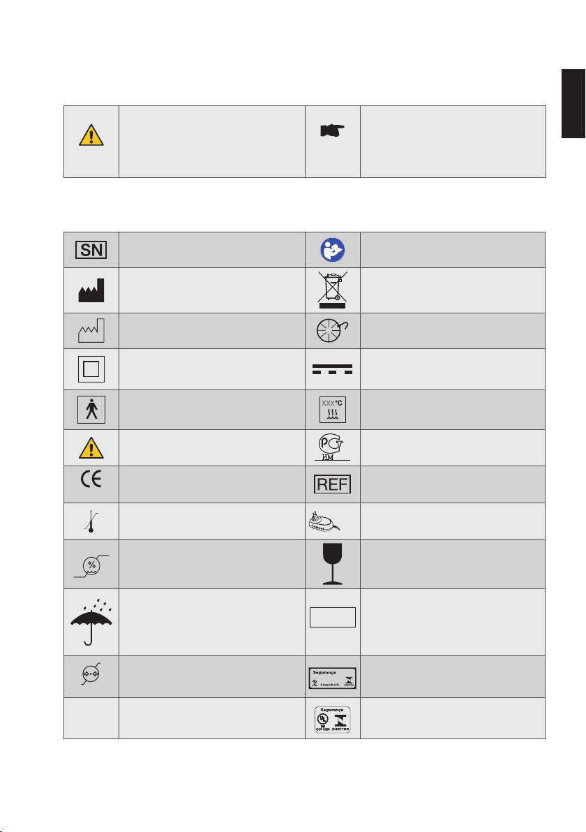
5
䣚䣚䣚
05
Model:
TR30RAM120
90%
20%
2. Identification des pictogrammes
2.1. Pictogrammes utilisés dans ce mode d’emploi
Le non-respect de ces consignes durant
MISE EN GARDE
l’utilisation risque d’endommager le produit
et de mettre en danger l’utilisateur ou le
patient.
REMARQUE
Information supplémentaire, explication sur
le fonctionnement et les performances.
2.2. Pictogrammes apposés sur l’emballage, le dispositif et ses composants
Numéro de série
Fabricant
Date de fabrication Branchement de la pédale
Produit de classeII
Partie appliquée de type BF
Mise(s) en garde
Marquage CE et numéro d’identification de
l’organisme notifié
0123
+ 50° C
- 20° C
Limitation de température
Se reporter aux instructions d’utilisation
(action obligatoire)
Ne pas mettre au rebut avec les déchets
ménagers
Courant continu
(branchement du chargeur de batterie sur
le secteur)
Stérilisable à la vapeur jusqu’à xxx°C,
température indiquée sur le pictogramme
Logo GOST, produit conforme aux normes
de sécurité russes (GOST-R).
Référence catalogue (référence pour des
commandes ultérieures)
Utiliser le dispositif uniquement avec le
chargeur de batterie fourni
fr
Limitation d’humidité Fragile!
Indice de protection (IP) contre la
Conserver au sec
IPN
poussière et l’eau: les deux chiffres (N1
1N2
et N2) indiquent respectivement le degré
de protection contre les corps solides et
les liquides
106 kPa
50 kPa
Limitation de pression atmosphérique
®
Logo INMETRO sur l’emballage: produit
conforme aux normes de sécurité
brésiliennes
Logo INMETRO sur le dispositif,
®
produit conforme aux normes de sécurité
brésiliennes
Page 78
6
3. Usage prévu, utilisateur concerné et population de patients
fr
RÉSERVÉ À UN USAGE DENTAIRE
Le VDW.SILVER® RECIPROC® est un dispositif médical
conforme à la directive 93/42/CEE relative aux dispositifs médicaux, modifiée par la Directive 2007/47/CE.
Le moteur d’endodontie est utilisé pour le traitement de
canaux radiculaires à l’aide d’instruments endodontiques
en mode de rotation continue avec contrôle du couple et
en mode réciproque.
Le présent dispositif doit être utilisé exclusivement dans
les milieux hospitaliers, les cabinets de médecine générale ou les cliniques dentaires et uniquement par des
professionnels dentaires qualifiés (dentistes et endodontistes).
N’utilisez pas le dispositif pour les implants ou tout autre
soin dentaire qui ne relève pas de l’endodontie.
Tous les patients, à l’exception des enfants, peuvent être
traités avec le VDW.SILVER
en termes de genre, d’origine et d’âge.
®
RECIPROC®, sans restriction
4. Contre-indications
L’utilisation du VDW.SILVER®RECIPROC® est contre-indiquée pour les patients ou les utilisateurs porteurs d’un
implant médical actif (stimulateur cardiaque, implant
cochléaire…).
L’innocuité et l’efficacité n’ont pas été établies chez
les femmes enceintes ou allaitantes ainsi que chez les
enfants.
L’utilisateur final du dispositif doit être en mesure de porter un jugement clinique.
5. Mises en garde
Veuillez lire les mises en garde suivantes avant utilisation.
MISES EN GARDE
• Afin de prévenir tout risque d’explosion, n’utilisez pas ce dispositif en présence de gaz
anesthésiques inflammables, de gaz comburants (protoxyde d’azote N
exemple) ou de solvants volatiles (éther ou
alcool par exemple).
O et oxygène par
2
• Toute modification de ce dispositif médical est
interdite. S’il s’avère nécessaire de remplacer
l’un des composants, veuillez contactez le
centre SAV.
• Ne connectez pas le
VDW.SILVER
tifs ou systèmes. Ne connectez aucun dispositif au VDW.SILVER®RECIPROC® via son port
USB. Ce port USB est exclusivement prévu à
des fins d'entretien ou de mises à jour du logiciel par les techniciens autorisés.
• Les composants du VDW.SILVER
sont ni désinfectés ni stérilisés à leur livraison: les composants tels que l’unité centrale,
le micromoteur et le câble du micromoteur
doivent être désinfectés avant la première
utilisation, puis retraités de façon appropriée après toute utilisation. Le contre-angle
VDW 6:1 doit être stérilisé avant la première
utilisation puis entièrement retraité après
chaque utilisation.
• Utilisez exclusivement le chargeur de batterie
fourni.
• Le chargeur de batterie doit être accessible à
tout moment pour pouvoir le débrancher rapidement du secteur.
• Utilisez exclusivement le contre-angle VDW6:1
avec le dispositif. La précision du couple et de
la vitesse de rotation n’est garantie qu’en cas
d’utilisation du contre-angle VDW6:1.
• En cas de fuite du VDW.SILVER
pouvant provenir de la batterie, cessez immédiatement d’utiliser le dispositif et débranchez-le du secteur. Contactez le centre SAV.
• En cas de dysfonctionnement lors de l’utilisation du dispositif, éteignez le micromoteur,
débranchez le dispositif du secteur et contactez le centre SAV.
• Lorsque vous utilisez des instruments endodontiques, respectez les instructions fournies
dans le manuel du fabricant de la lime ainsi
que les instructions d’utilisation du contreangle VDW6:1.
• L’utilisation d’une lime rotative en mode réciproque peut provoquer sa rupture. N‘utilisez
jamais de lime rotative en mode réciproque.
Vérifiez le mode indiqué sur l‘écran avant l‘utilisation.
®
RECIPROC® à d’autres disposi-
®
RECIPROC
®
RECIPROC®
®
Page 79

7
• L’utilisation d’une lime de travail en mode
réciproque en mode de rotation continue peut
provoquer sa rupture. N‘utilisez jamais de lime
de travail en mode réciproque en mode de
rotation continue. Vérifiez le mode indiqué sur
l‘écran avant l‘utilisation.
• Les valeurs de couple et de vitesse de rotation
autorisées peuvent être modifiées par le fabricant des limes sans communication préalable.
Par conséquent, les valeurs préréglées dans
la bibliothèque doivent être vérifiées avant
l’utilisation. Les valeurs indiquées sur l’écran
sont précises et fiables seulement si le contreangle VDW6:1 a fait l’objet d’un entretien et
d’une lubrification appropriés.
• Aucune lime ne doit être introduite pendant le
calibrage. La vitesse de rotation du micromoteur variant depuis sa valeur minimale jusqu’à
sa valeur maximale durant le calibrage, il
y a un risque de blessure. Le contre-angle
VDW 6:1 doit systématiquement être calibré
avant son utilisation et sans aucune lime.
• N’introduisez rien dans le micromoteur. Ne
lubrifiez pas le micromoteur car la lubrification
peut l’endommager et perturber son fonctionnement.
• Il est impératif d’utiliser une digue dentaire et
de porter des gants lors du traitement avec le
VDW.SILVER
®
RECIPROC®.
MISES EN GARDE
• Afin de prévenir tout risque d’explosion, n’utilisez pas ce dispositif en présence de gaz
anesthésiques inflammables, de gaz comburants (protoxyde d’azote N
exemple) ou de solvants volatiles (éther ou
alcool par exemple).
• En cas de perturbations électromagnétiques,
prenez les précautions suivantes pour prévenir
tout dysfonctionnement général du dispositif:
- L’utilisation de pièces autres que celles
fournies ou répertoriées en tant qu’accessoires peut avoir un impact négatif sur la
compatibilité électromagnétique.
- Référez-vous systématiquement aux infor-
mations fournies au chapitre «Compatibilité électromagnétique».
- En cas de dysfonctionnement du dispositif
vraisemblablement induit par des perturbations électromagnétiques, vérifiez tout
d’abord les câbles puis éloignez les équipements de communication RF portables
et mobiles placés à proximité pour éliminer toute interférence.
- Cessez d’utiliser le dispositif si les pertur-
bations électromagnétiques persistent et
contactez le centre SAV pour obtenir une
assistance.
O et oxygène par
2
fr
6. Précautions
Veuillez lire les précautions suivantes avant l’utilisation.
Le fabricant décline toute responsabilité en cas d’utilisa-
tion du VDW.SILVER
autres que celles indiquées dans le présent protocole
d’utilisation.
®
RECIPROC® pour des applications
7. Effets secondaires
Il n’y a pas d’effets secondaires connus.
8. Mise en service (étape par étape)
Dans ce chapitre, vous trouverez toutes les informations
nécessaires à la mise en service et à l’utilisation du
VDW.SILVER
®
RECIPROC®.
Page 80
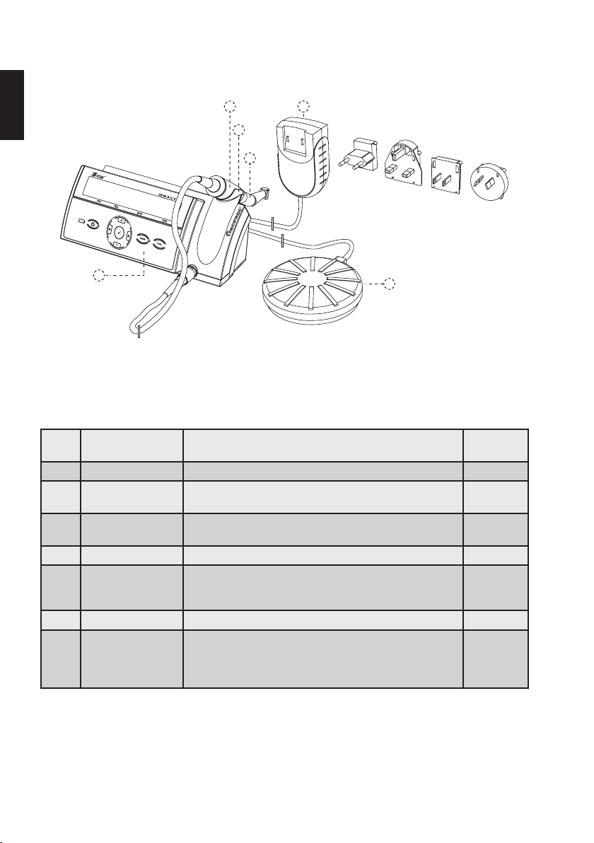
8
8.1. Composants et accessoires fournis
Le VDW.SILVER®RECIPROC® est fourni avec les composants répertoriés ci-après:
fr
(
,
)
+
'
Fig.1 VDW.SILVER®RECIPROC
N° de
RÉF. Description de la pièce
®
*
pièce
1) V04 1163 000 000 Dispositif VDW.SILVER®RECIPROC
®
2) - Micromoteur avec câble et connecteur
(longueur du câble: 1,8m)
3) V041 079 000 000 Contre-angle VDW6:1 (emballé séparément, avec son mode
d’emploi)
4) V041 107 000 510 Pédale (longueur de câble: 1,8m) 1
5) V041 107 000 517 Chargeur de batterie (avec anneau en ferrite) avec adaptateurs
électriques interchangeables U.E., R.U., USA, AUS (longueur de
câble: 1,8m)
6) - Socle de la pièce à main 1
®
Manuel utilisateur du VDW.SILVER
RECIPROC®
Le manuel utilisateur (en anglais) peut être téléchargé sur
https://www.vdw-dental.com/en/service/information-material/
directions-for-use/
Quantité
1
1
1
1
1
Page 81
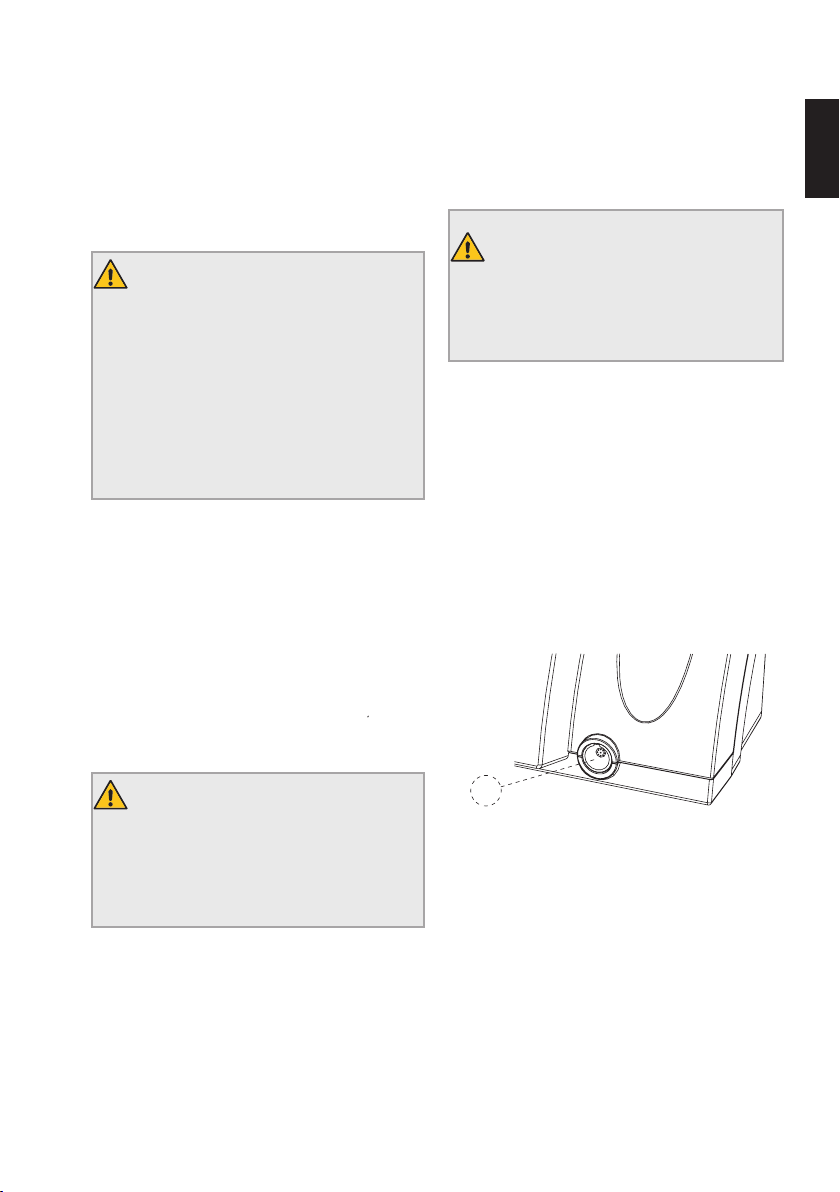
9
8.2. Mise en route
8.2.1. Préparation
1) Déballez soigneusement l’unité centrale et les
accessoires et placez-les sur une surface plane, à
l’emplacement désiré. Tenez compte des conditions
ambiantes spécifiées au chapitre "14. Caractéristiques
techniques" pour le choix de l’emplacement.
MISE EN GARDE
Le dispositif nécessite des précautions de
sécurité particulières concernant la compatibilité électromagnétique (CEM). Conformez-vous strictement aux informations CEM
fournies dans ce manuel lors de l’installation
et l’utilisation. Il est particulièrement important de ne pas utiliser le dispositif à proximité
de lampes fluorescentes, d’émetteurs radios,
de télécommandes, d’équipements de communication RF portables ou mobiles.
2) À l’ouverture de l’emballage et avant l‘installation,
examinez le dispositif pour déceler d‘éventuels dommages et vérifiez la présence de tous les composants.
Veuillez signaler au fournisseur tout composant manquant ou tout dommage survenu lors du transport dans
les 24heures suivant la réception du dispositif.
3) Vérifiez que le numéro de série du dispositif qui
figure sous l’unité centrale correspond à celui indiqué
sur l’emballage et les documents de transport.
4) Vérifiez que le numéro de série du contre-angle
VDW6:1 correspond avec celui indiqué sur son emballage.
5) Nettoyez, désinfectez et stérilisez le contre-angle
VDW6:1 (cf. les instructions d’utilisation séparées).
6) Nettoyez et désinfectez la face avant de l’unité centrale, le micromoteur ainsi que le câble du micromoteur.
Cf. chapitre «9 Nettoyage, désinfection et stérilisation».
MISE EN GARDE
En cas de fuite du dispositif, cessez immédiatement son utilisation et débranchez le
chargeur de batterie du secteur. Contactez le
centre SAV.
7) Ne placez pas le dispositif dans un endroit humide
ou à un emplacement où celui-ci sera constamment en
contact avec des liquides de tout type.
8.2.2. Vue des connectiques
Les câbles du micromoteur, de la pédale et du chargeur
de batterie ne doivent être ni pincés ni tirés lors du branchement ou du débranchement.
Assurez-vous que les câbles ne constituent pas des obstacles et ne limitent pas la mobilité.
fr
MISE EN GARDE
Les composants ne sont ni stérilisés ni désinfectés à leur livraison. Suivez les instructions
détaillées au chapitre "9. Nettoyage, désinfection et stérilisation" avant d’utiliser le dispositif.
A
Fig.2 Connectique avant
Vue avant
A) Connectique du micromoteur.
Page 82
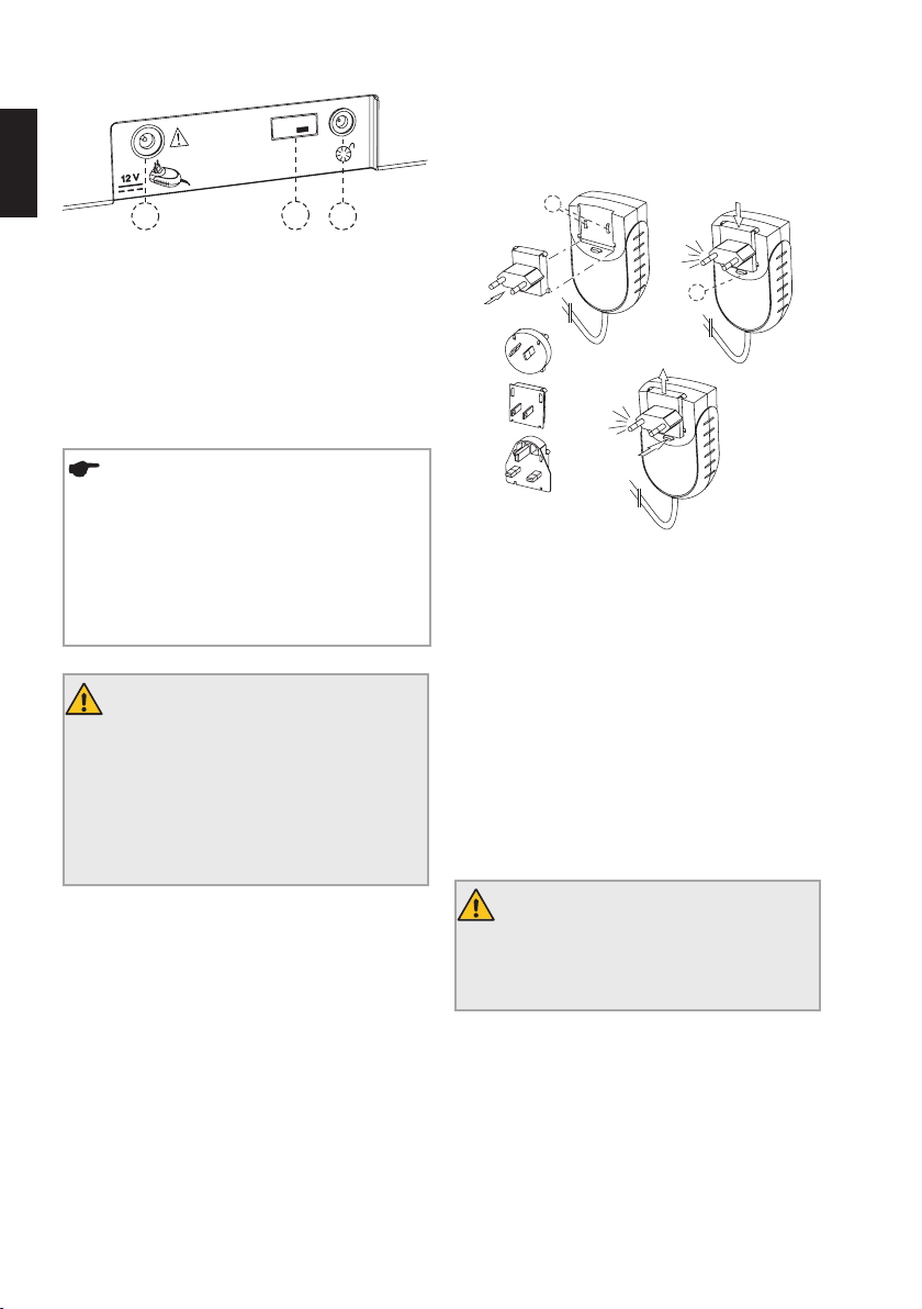
fr
Fig.3 Connectique arrière
10
8.2.3. Chargeur de batterie
1) Sélectionnez l’adaptateur correspondant à votre
Model:
TR30RAM120
B
DC
prise électrique (cf. Fig.4).
E
Vue arrière
B) Connectique du chargeur de batterie.
C) Connectique de la pédale.
D) Port USB pour les mises à jour (réservé aux techni-
ciens de maintenance).
REMARQUE
Le port USB (Fig. 3, D) est utilisé pour installer des mises à jour logicielles ou réaliser
la maintenance du dispositif. Ce port doit
être utilisé exclusivement par les techniciens
autorisés. Il est protégé par un cache qui doit
également être retiré uniquement par les
techniciens autorisés.
MISE EN GARDE
Ne connectez pas le
VDW.SILVER
®
RECIPROC® à d’autres dispositifs ou systèmes. Ne connectez aucun dispositif au VDW.SILVER®RECIPROC® via son port
USB. Ce port USB est exclusivement prévu à
des fins d'entretien et de mises à jour logicielles par les techniciens autorisés.
F
Fig.4 Chargeur de batterie et adaptateurs électriques
2) Placez l‘adaptateur sur les deux contacts du chargeur (Fig.4, E) et poussez-le vers le bouton de verrouillage jusqu‘à ce qu‘il s‘enclenche. Appuyez sur le bouton
de verrouillage pour changer d‘adaptateur.
3) Branchez le câble du chargeur de batterie sur la
prise adéquate (Fig.3, B), au dos du dispositif.
4) Branchez le chargeur de batterie sur le secteur en
veillant à ce que celui-ci reste accessible à tout moment
pour permettre un débranchement rapide. La batterie
commence à se charger.
5) Chargez complètement la batterie avant d’utiliser le
dispositif pour la première fois. Pour plus d’informations
sur l’entretien de la batterie, cf. chapitre 8.2.5.
MISE EN GARDE
Le chargeur de batterie doit être accessible à
tout moment pour pouvoir le débrancher rapidement du secteur.
Page 83
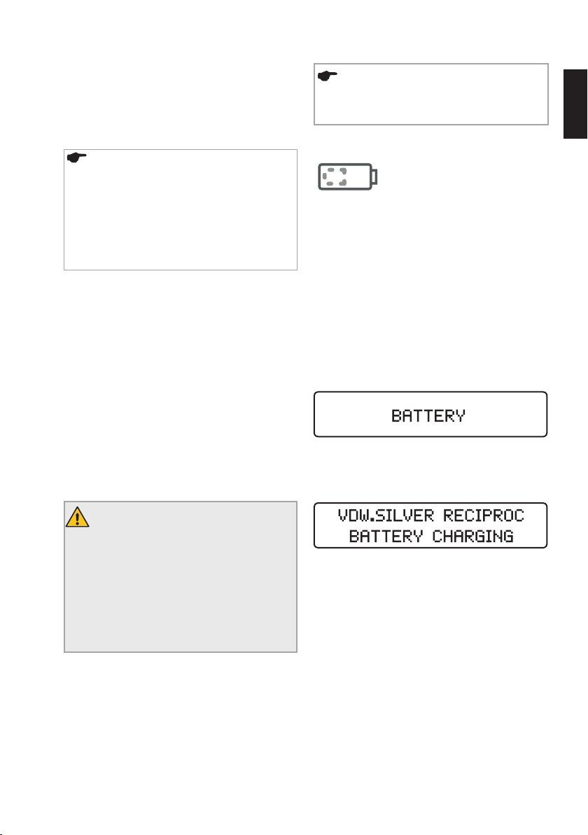
11
8.2.4. Micromoteur, contre-angle VDW6:1 et
pédale
6) Branchez la fiche du câble du micromoteur dans la
prise correspondante à l‘avant de l‘unité centrale (Fig.2,
A).
REMARQUE
La prise (Fig.2, A) est un connecteur va-etvient. Placez le point rouge du connecteur
mâle vers le haut pour permettre l’insertion
dans le connecteur femelle. Ne vissez pas le
câble dans la prise. Pour débrancher le câble,
tirez sur son extrémité en métal. Ne dévissez
pas le connecteur pour le débrancher.
7) Retirez la buse de pulvérisation noire du contreangle VDW6:1.
8) Insérez le contre-angle VDW6:1 dans le micromoteur (consultez également les instructions d’utilisation du
contre-angle VDW6:1 séparées).
9) Insérez le connecteur de la pédale dans sa prise
(Fig.3, C), à l’arrière de l‘unité centrale.
8.2.5. Batterie
Le VDW.SILVER® RECIPROC® est alimenté par une batterie nickel-hydrure métallique (NiMH). Vous trouverez
dans ce chapitre toutes les informations nécessaires
pour utiliser correctement la batterie.
REMARQUE
Chargez la batterie entièrement avant sa première utilisation.
Affichage DEL de la batterie
L’affichage DEL de la batterie utilise
trois couleurs différentes pour indiquer
l‘état actuel de la batterie:
Diode verte: indique une capacité de batterie comprise
entre 20 et 100%.
Diode rouge qui clignote: la batterie doit être chargée.
Le dispositif va s’éteindre d’ici quelques minutes.
Si la diode de la batterie devient rouge et clignote en
cours d’utilisation, branchez immédiatement le dispositif
sur le chargeur de batterie pour éviter un arrêt du dispositif pendant le traitement.
Cet avertissement de la batterie doit être considéré
comme un signal de HAUTE priorité.
Avant l’arrêt du moteur, un signal d’alarme retentit pendant 22 secondes à deux fréquences différentes et le
message suivant apparaît:
Diode orange qui clignote: le chargeur est correctement
branché et la batterie est en cours de charge. Le message suivant est affiché sur l‘écran:
fr
MISES EN GARDE
• Le dispositif ne doit être ouvert en aucune
circonstance. Il ne contient aucune pièce
requérant un entretien. Si la batterie doit être
remplacée, contactez le centre SAV.
• En cas de fuite du VDW.SILVER
pouvant provenir de la batterie, cessez immédiatement d’utiliser le dispositif et débranchez-le du secteur. Contactez le centre SAV.
®
RECIPROC®
Il est également possible d’utiliser le
VDW.SILVER® RECIPROC® pendant la charge, sans que
cela augmente sensiblement la durée de charge. Le
chargeur est suffisamment puissant pour alimenter
directement le micromoteur.
Lorsque la batterie est complètement chargée, sa diode
passe au vert.
Page 84
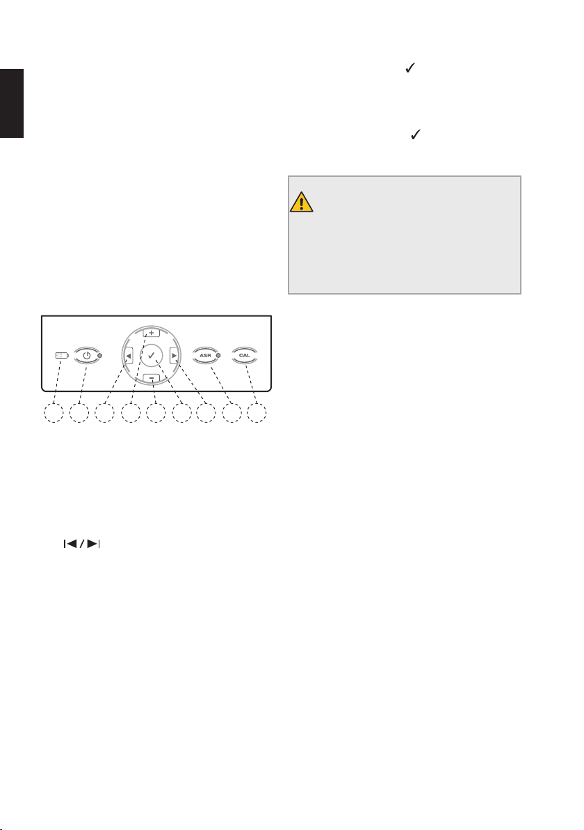
12
Durée de charge et de fonctionnement
La charge de la batterie peut durer jusqu’à 3heures si
celle-ci était complètement épuisée.
fr
Si la batterie est correctement chargée, elle dispose
d’une autonomie de 2 heures avant de devoir être
rechargée.
Pour une longue durée de vie de la batterie
Afin de garantir une durée de vie optimale de la batterie, nous vous recommandons de toujours travailler avec
l’alimentation de la batterie et de recharger celle-ci uniquement lorsqu’elle est complètement épuisée.
8.3. Interface utilisateur
8.3.1. Clavier
1
2
Fig.5 Clavier
1) Marche/Arrêt
Met en marche et arrête le dispositif.
2) Affichage DEL de la batterie
Indique le niveau actuel de la batterie (pour plus d’informations, cf. chapitre "8.2.5. Batterie").
3+4)
Font défiler vers la droite ou la gauche les différents
champs de la ligne inférieure de l‘écran : système de
limes, lime, couple et vitesse. Le champ actif est indiqué
par une flèche (en mode de rotation continue uniquement).
5+6) +/–
Font défiler les systèmes de limes ou les limes et modifient individuellement les valeurs du couple ou de la
vitesse dans tous les systèmes de limes rotatives.
3
6
5
4
7
7) Touche de confirmation
Confirme les modifications des paramètres de couple et
de vitesse pour tous les systèmes autorisant des modifications. Rétablit également les paramètres par défaut
en cas d’appui simultané sur la touche Marche/Arrêt.
La touche de confirmation permet également de
démarrer le micromoteur sans utiliser la pédale.
8) CAL
MISE EN GARDE
Aucune lime ne doit être introduite pendant le
calibrage. La vitesse de rotation du micromoteur variant depuis sa valeur minimale jusqu’à
sa valeur maximale durant le calibrage, il y a
un risque de blessure.
Calibre le contre-angle VDW6:1 pour garantir la précision du couple après chaque changement ou lubrification (pour plus d’informations, cf. chapitre "8.4.2. CAL :
calibrage").
9) ASR - Mode de rotation continue uniquement
Diode verte : en mode de rotation continue, inversion
automatique du sens de rotation une fois la valeur de
8
9
couple préréglée atteinte.
Diode rouge: en mode de rotation continue, inversion
du sens de rotation sans limite de couple, via la pédale.
Diode éteinte: en mode de rotation continue, arrêt du
micromoteur une fois la valeur de couple préréglée
atteinte.
La fonction ASR est désactivée en mode réciproque
(diode éteinte).
Page 85
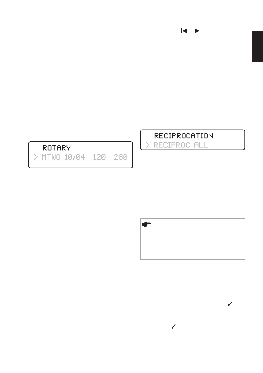
13
8.3.2. Écran
Lorsque le dispositif est mis en marche, toutes les diodes
s’allument et un écran de bienvenue apparaît. Lors des
utilisations suivantes, l’écran affiche le dernier système
de limes utilisé.
Lorsque vous activez le dispositif en mode veille (en
actionnant la pédale ou en appuyant sur une touche
quelconque du clavier), l’écran affiche également le dernier système de limes utilisé avant le mode veille.
Ligne supérieure:
Indique le mode sélectionné – ROTARY (mode rotation
continue) ou RECIPROCATION (mode réciproque ).
Ligne inférieure en mode de rotation continue:
Affiche les champs sys(système de limes), file (lime),
gcm (couple) et rpm (vitesse de rotation):
sys file gcm rpm
sys
Indique le système de limes sélectionné (par ex. MTWO
pour Mtwo
CHOICE, etc.)
file
Indique la lime sélectionnée.
gcm
Indique la valeur limite préréglée du couple (fonction
désactivée en mode réciproque). Le couple est indiqué en gcm (gramme-force par centimètre: 1 gcm =
0,0981Nmm).
rpm (tr/min)
Indique la vitesse de rotation de la lime en rpm ou tr/
min (tours par minute) (fonction désactivée en mode
réciproque).
Si les paramètres standard relatifs à la vitesse de rotation
sont modifiés, le symbole ’ précède la nouvelle valeur.
®
, FM pour FlexMaster®, DR’s pour DR’S
• Utilisez les touches
vers la droite ou la gauche (en mode de rotation continue uniquement).
• Utilisez les touches + et - pour faire défiler les systèmes de limes ou les limes et modifier individuellement les valeurs du couple ou de la vitesse dans tous
les systèmes de limes rotatives.
• Les paramètres du moteur ne peuvent pas être modifiés dans les systèmes avec mode réciproque.
• Lorsque les valeurs par défaut du couple ou de la
vitesse sont modifiées, le symbole ‘ précède la valeur
du couple ou de la vitesse.
Ligne inférieure en mode réciproque:
Indique le système réciproque utilisé.
Contrairement au mode de rotation continue, il est
impossible de sélectionner une lime individuelle en mode
réciproque puisque tous les paramètres du moteur s’appliquent à l’ensemble du système (indiqué par RECIPROC
ALL).
et pour déplacer la flèche
8.3.3. Pédale
REMARQUES
• Pour accroître la durée de vie des câbles, ne
les pliez pas.
• Si la pédale a tendance à glisser, nettoyez ses
pieds en caoutchouc.
Le micromoteur peut être démarré de deux manières
différentes:
• La pédale est actionnée et le micromoteur fonctionne
tant qu’elle reste actionnée.
• Le micromoteur peut également être démarré en
appuyant sur la touche de confirmation
dant 1,5seconde. Le micromoteur peut être arrêté en
appuyant sur n’importe quelle touche ou sur la pédale.
Si le micromoteur est actionné à l’aide de la touche de
confirmation , il s’arrête automatiquement après
5minutes de non-utilisation afin d’économiser la batterie.
pen-
fr
Page 86
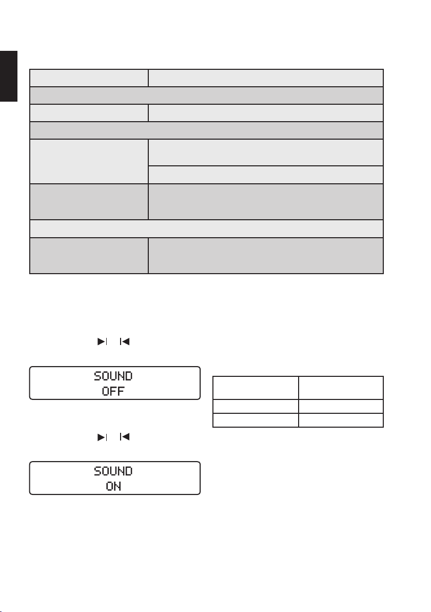
14
8.3.4. Signaux sonores
Tous les signaux sonores sont activés par défaut à la livraison du dispositif:
fr
Composants Signal sonore
Clavier
Touches Signal de confirmation à chaque pression des touches.
Moteur
Signal sonore lorsque le couple en mode de rotation continue dépasse
Mode de rotation continue
environ 75% de la valeur préréglée.
Signal intermittent en cas de rotation continue dans le sens antihoraire.
Mode réciproque
longueur de l‘instrument. Pour plus d’informations, cf. chapitre "8.5.4.
Mode réciproque".
Batterie
Un signal sonore fort retentit avant l’arrêt du dispositif dû à un faible
Signal sonore lorsqu’une pression accrue est exercée sur toute la
Niveau de la batterie
niveau de la batterie. Cet avertissement de la batterie doit être considéré
comme un signal d’alarme de HAUTE priorité.
Désactivation et activation des signaux sonores
Pour désactiver les signaux sonores, appuyez simultanément sur les touches
et : un bip est émis et le
message suivant s’affiche:
Pour réactiver les signaux sonores, appuyez simultanément sur les touches et : un bip est émis et le
message suivant s’affiche:
8.3.5. Bibliothèque de limes
Le dispositif contient une bibliothèque de limes avec les
systèmes prédéfinis suivants:
Systèmes pour le mode réciproque:
Nom du système de limes Nom affiché sur le
®
RECIPROC
WaveOne™ WAVEONE ALL
Les paramètres relatifs au moteur s’appliquent à l’intégralité du système et sont indiqués par RECIPROC ALL et
WAVEONE ALL.
dispositif
RECIPROC ALL
Page 87
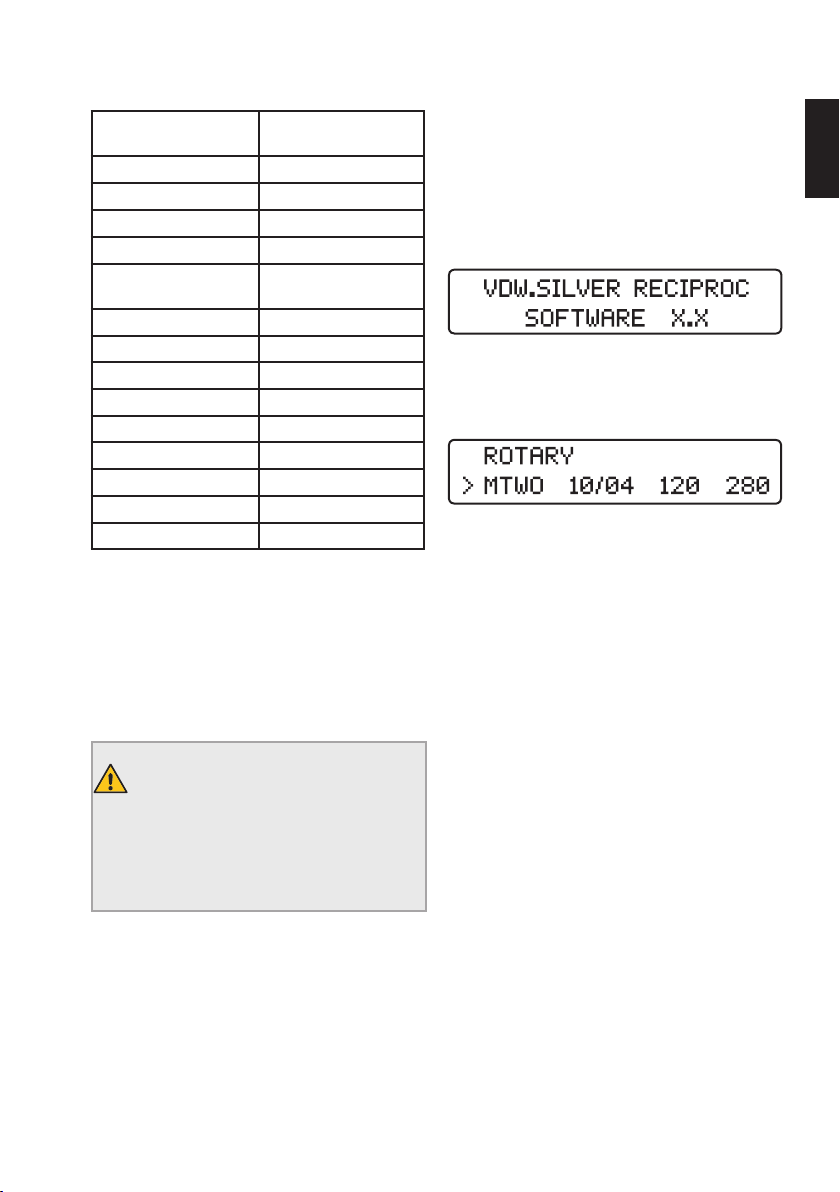
15
Systèmes de rotation continue:
Nom du système de limes Nom affiché sur le
VDW.ROTATE VROT
®
Mtwo
FlexMaster
Gates Glidden GATE
Dr’s Choice Individual
Program
TruNatomy™ TN
ProFile
ProGlider
ProTaper
ProTaper
K3™ K3
FlexMaster
FlexMaster
Lentulo LENT
®
®
®
®
Universal PTU
®
Next PTN
®
Retreatment1 FMR1
®
Retreatment2 FMR2
dispositif
MTWO
FM
DR’S
PF
PG
Avant de démarrer le micromoteur, assurez-vous que le
système de limes indiqué sur l’écran correspond à la lime
utilisée. Veuillez vous référer au protocole d’utilisation de
la lime utilisée pour connaître les paramètres préconisés.
Les valeurs affichées par le dispositif sont précises et
fiables seulement si le contre-angle VDW6:1 fait l’objet
d’un entretien approprié.
MISE EN GARDE
Lorsque vous utilisez des instruments endodontiques, respectez les instructions fournies dans le manuel du fabricant ainsi que
les instructions d’utilisation du contre-angle
VDW6:1.
8.4. Fonctionnement
8.4.1. Mise en marche, mode veille et arrêt
fr
Mise en marche
Appuyez sur la touche Marche/Arrêt. Toutes les diodes
s’allument brièvement, ce qui permet de vérifier leur
fonctionnement. Un écran de bienvenue apparaît et
indique la version du logiciel.
Lors des sessions suivantes, l’écran indique la première
lime du dernier système utilisé avant l’arrêt du dispositif,
ou la dernière lime utilisée avant la mise en veille.
Mode veille
Si le dispositif n’est pas utilisé pendant 10min, il passe
automatiquement en mode veille pour économiser la batterie. L’écran s’éteint.
Pour quitter le mode veille, appuyez sur n’importe quelle
touche du clavier ou sur la pédale. Le dispositif se rallume et affiche la dernière fonction utilisée avant la mise
en veille.
Après 30minutes de veille, le dispositif se met hors tension pour économiser la batterie.
Pour remettre en marche le dispositif, appuyez sur la
touche Marche/Arrêt.
Arrêt
Appuyez sur la touche Marche/Arrêt pour arrêter le dispositif. La diode de la batterie s’éteint, sauf si la batterie
est en cours de charge.
Page 88
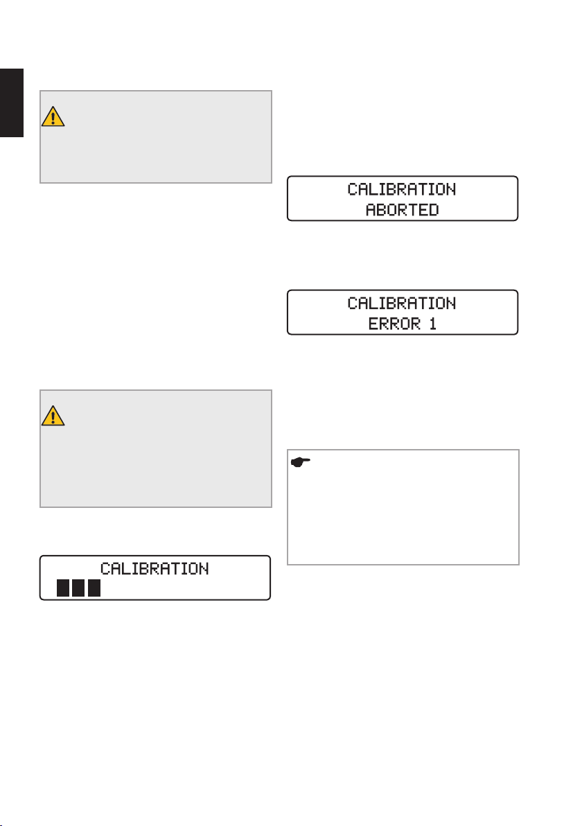
16
8.4.2. CAL: calibrage
fr
MISE EN GARDE
La précision des paramètres de travail n’est
garantie qu’en cas d’utilisation d’un contreangle VDW6:1 correctement entretenu.
Le calibrage du micromoteur définit automatiquement la
vitesse de rotation pour garantir la précision du couple.
Le calibrage est nécessaire:
• après un changement du micromoteur,
• après un changement et retraitement du contre-angle
VDW6:1, et au moins une fois par semaine (cf. également le mode d’emploi séparé du contre-angle
VDW6:1).
Début du calibrage
1) Connectez le contre-angle VDW 6:1 au micromo-
teur, sans lime.
MISE EN GARDE
Aucune lime ne doit être introduite pendant le
calibrage. La vitesse de rotation du micromoteur variant depuis sa valeur minimale jusqu’à
sa valeur maximale durant le calibrage, il y a
un risque de blessure.
2) Appuyez sur la touche CAL. Le processus de
calibrage est lancé et le message suivant s’affiche:
3) Le processus s’arrête automatiquement, dès le
calibrage terminé (toutes les barres noires sont visibles
sur l’écran).
Annulation du calibrage
Le processus de calibrage peut être interrompu à tout
moment en appuyant sur la pédale ou sur l’une des
touches du clavier. Le message suivant s’affiche alors:
Messages d’erreur possibles
Si le processus de calibrage ne peut pas être exécuté
ou achevé correctement, le message suivant s’affiche:
Vous trouverez toutes les informations concernant les messages d’erreur possibles, tels que
ERROR1 ou ERROR2, au chapitre "10.2. Dépannage".
8.4.3. ASR: Automatic Stop Reverse
REMARQUE
La fonction ASR peut être activée uniquement
en mode de rotation continue. À la livraison,
la fonction ASR est activée pour le mode de
rotation continue (diode verte).
En mode réciproque, la fonction ASR est
désactivée (diode éteinte).
La vitesse de rotation du micromoteur varie automatiquement de sa valeur minimale à sa valeur maximale
pour mesurer l’inertie du contre-angle.
En mode de rotation continue, la fonction ASR peut
être modifiée en appuyant sur la touche ASR. La diode
change de couleur selon la fonction sélectionnée:
Diode verte: lorsque le couple préréglé est atteint, le
micromoteur inverse automatiquement son sens de rotation (sens antihoraire). Dès que la lime ne rencontre plus
de résistance, le micromoteur repart automatiquement
en rotation avant (sens horaire).
Page 89
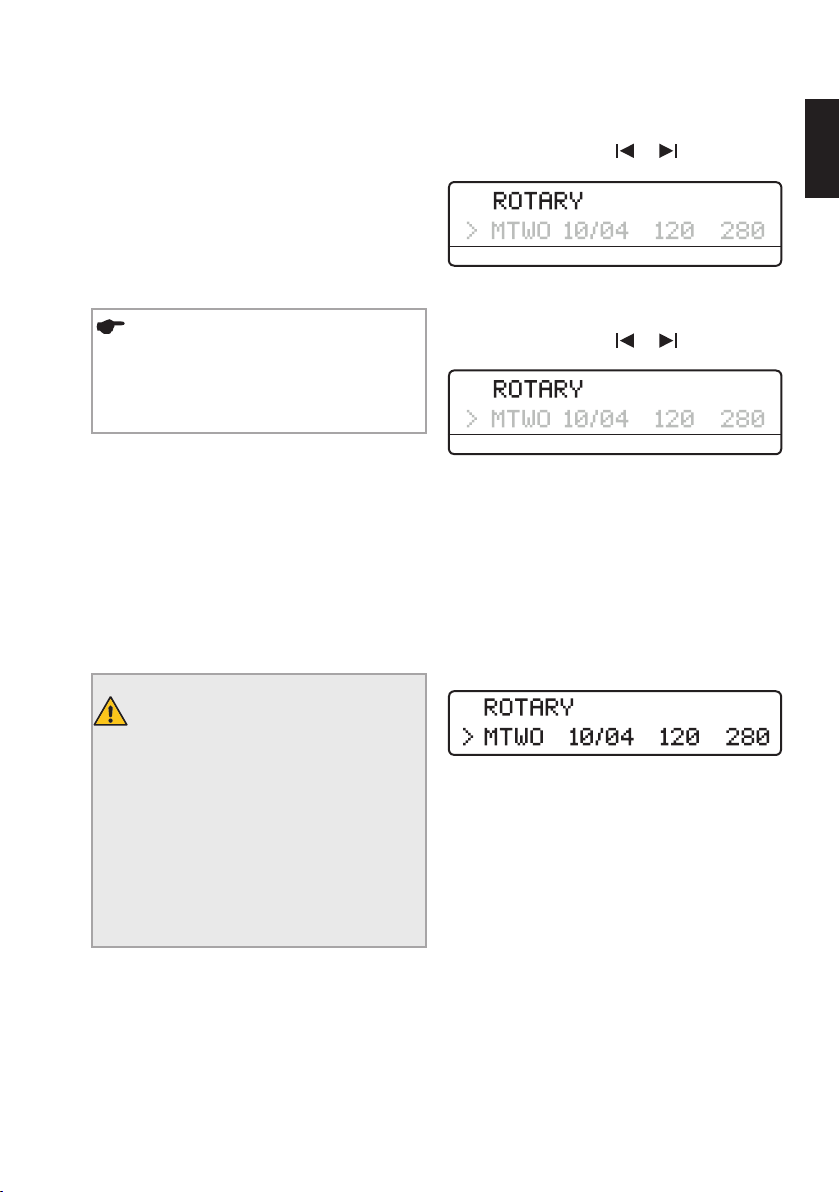
17
Diode rouge: le micromoteur passe automatiquement
en rotation arrière (sens antihoraire), sans contrôle du
couple.
Diode éteinte: en mode de rotation continue, lorsque le
couple préréglé est atteint, le micromoteur s’arrête automatiquement. En cas de nouvelle pression de la pédale,
le micromoteur démarre en rotation arrière (sens antihoraire). Dès que la lime ne rencontre plus de résistance, le
micromoteur repart automatiquement en rotation avant
(sens horaire).
REMARQUE
La fonction ASR peut être paramétrée pour
chaque lime en mode de rotation continue. Le
paramètre standard est réactivé (diode verte)
dès que vous choisissez une autre lime.
Signaux sonores:
• lorsque le couple dépasse environ 75% de la valeur
préréglée;
• lorsque le micromoteur est en rotation arrière.
8.5. Sélection d’un système de limes/
de limes
L’écran affiche systématiquement le dernier système de
limes utilisé ou la dernière lime correspondante utilisée.
Pour faire une nouvelle sélection, procédez comme suit:
1) À l’aide des touches
champ sys (flèche):
/ , sélectionnez le
sys file gcm rpm
2) À l’aide des touches +/–, sélectionnez le système de
limes souhaité (défilement vers le haut ou vers le bas).
3) À l’aide des touches / , sélectionnez le
champ lime (flèche):
sys file gcm rpm
4) À l’aide des touches +/–, sélectionnez la lime souhaitée (défilement vers le haut ou vers le bas).
5) Il n’est pas nécessaire de confirmer le paramètre.
La lime ou le système souhaité est maintenant activé.
8.5.1. Mode de rotation continue
Lorsqu’un système de limes est sélectionné en mode de
rotation continue, la première ligne de l’écran indique:
fr
MISE EN GARDE
Vérifiez systématiquement le mode indiqué
sur l’écran avant l’utilisation:
- L’utilisation en mode réciproque d’une lime
rotative peut provoquer sa rupture. N‘utilisez
jamais de lime rotative en mode réciproque.
- L’utilisation en mode de rotation continue
d’une lime de travail en mode réciproque peut
provoquer sa rupture. N‘utilisez jamais de
lime de travail en mode réciproque en mode
de rotation continue.
La deuxième ligne affiche automatiquement la première
lime de la séquence.
En mode de rotation continue, les valeurs du couple et de
la vitesse de rotation peuvent être modifiées individuellement pour tous les systèmes de limes. Pour ce faire,
procédez comme décrit au point "8.5.2. Modification
du couple et de la vitesse de rotation (mode de rotation
continue uniquement)".
Page 90
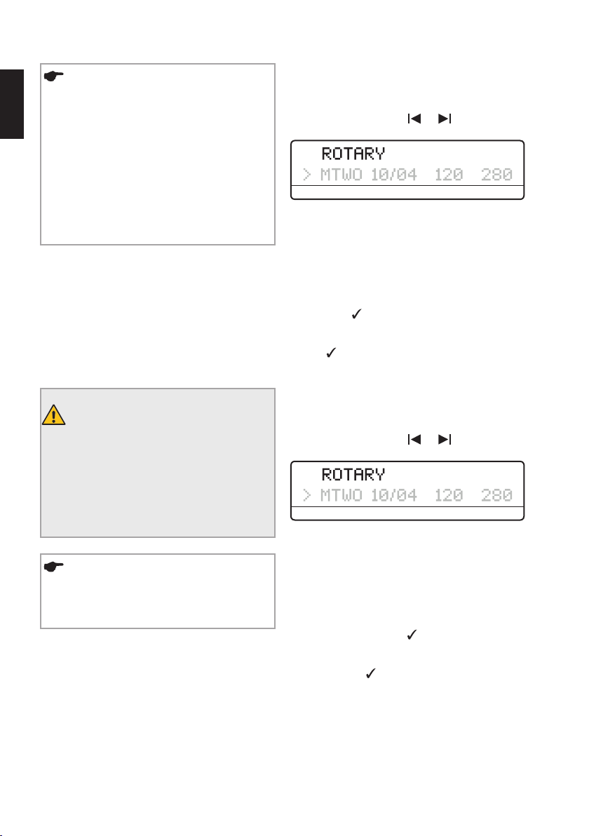
18
REMARQUES
fr
• La fonction ASR peut être activée uniquement
en mode de rotation continue. Lors de livraison, la fonction ASR est activée (diode verte).
Appuyez sur la touche ASR pour sélectionner
les différentes fonctions (pour plus d’informations, cf. chapitre "8.4.3. ASR: Automatic Stop
Reverse")
• Si la lime rotative est bloquée dans le canal,
sélectionnez la fonction ASR de rotation arrière
(diode rouge), redémarrez le moteur et désengagez la lime délicatement.
8.5.2. Modification du couple et de la vitesse
de rotation (mode de rotation continue
uniquement)
En mode de rotation continue, les valeurs du couple et de
la vitesse de rotation préréglées peuvent être modifiées
individuellement pour chaque système.
MISE EN GARDE
Des valeurs de couple et de vitesse de rotation supérieures aux valeurs recommandées
peuvent entraîner une rupture de la lime pendant le traitement.
Veuillez toujours vous référer au protocole
d’utilisation de la lime utilisée pour connaître
les paramètres préconisés.
Modification du couple
1) Sélectionnez la lime rotative souhaitée, comme
décrit précédemment (la flèche indique la sélection
active).
2) À l’aide des touches
champ gcm (flèche):
/ , sélectionnez le
sys file gcm rpm
3) À l’aide des touches +/–, sélectionnez le couple
souhaité (défilement vers le haut ou vers le bas). Lorsque
la valeur du couple est modifiée, celle-ci clignote. La
plage du couple s’étend de 20 à 410gcm par paliers
de 10gcm.
4) Une fois le couple sélectionné, enregistrez le nouveau paramètre en appuyant une fois sur la touche de
confirmation . Le champ du couple cesse alors de
clignoter et est précédé du symbole ‘. Si le paramètre
n’est pas enregistré par un appui sur la touche de confir-
mation , celui-ci ne peut pas être pris en compte et
le micromoteur ne démarre pas .
Modification de la vitesse de rotation
1) Sélectionnez la lime rotative souhaitée comme décrit
précédemment (la flèche indique la sélection active).
2) À l’aide des touches
champ rpm (flèche):
/ , sélectionnez le
sys file gcm rpm
REMARQUE
Les valeurs de couple et de vitesse de rotation ne peuvent pas être modifiées en mode
réciproque.
3) À l’aide des touches +/–, sélectionnez la vitesse
de rotation souhaitée (défilement vers le haut ou vers le
bas). Lorsque la valeur de la vitesse de rotation est modifiée, celle-ci clignote. La plage de la vitesse de rotation
s’étend de 250 à 1000tr/min par paliers de 10tr/min.
4) Une fois la vitesse de rotation sélectionnée, enregistrez le nouveau paramètre en appuyant une fois sur
la touche de confirmation
cesse alors de clignoter et est précédé du symbole ‘. Si le
paramètre n’est pas enregistré par un appui sur la touche
de confirmation
compte et le micromoteur ne démarre pas .
. Le champ de la vitesse
, celui-ci ne peut pas être pris en
Page 91
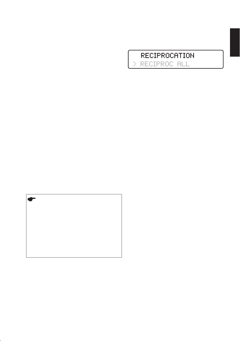
19
8.5.3. Dr’s Choice (mode de rotation continue uniquement)
Le programme personnalisé Dr‘s Choice vous permet
de composer votre propre séquence de limes. Vous avez
ainsi la possibilité de gérer votre sélection d’instruments.
Le dispositif est fourni avec 15valeurs de couple et de
vitesse de rotation par défaut (pour plus d’informations
sur les valeurs par défaut, cf. chapitre "15. Tableaux pour
le programme Dr´s Choice").
Pour modifier ces paramètres, il vous suffit de les remplacer comme décrit au chapitre "8.5.2. Modification
du couple et de la vitesse de rotation (mode de rotation
continue uniquement)". Pour garder une trace de vos
paramètres personnalisés, utilisez le tableau fourni au
chapitre "15. Tableaux pour le programme Dr´s Choice".
Pour restaurer les paramètres par défaut, veuillez suivre
la procédure détaillée au chapitre "8.6. Paramètres par
défaut".
8.5.4. Mode réciproque
Les instruments RECIPROC® et WaveOneTM sont spécialement conçus pour être utilisés en mode réciproque:
l‘instrument travaille dans un sens de coupe, puis se
désengage en tournant dans le sens inverse. Les angles
pour un travail en mode réciproque sont précis et propres
au modèle de l‘instrument.
REMARQUES
• Les limes de travail en mode réciproque
RECIPROC
des limes rotatives par les caractéristiques
suivantes: leur tige comporte une bague en
plastique coloré et leurs spires coupantes sont
inversées.
• En mode réciproque, la fonction ASR – prévue pour le mode de rotation continue – est
désactivée.
®
et WaveOne™ se distinguent
Le travail en mode réciproque
Lorsque l’une des limes de travail en mode réciproque
susmentionnées est sélectionnée, la première ligne de
l’écran affiche le message suivant:
Indiquez le système réciproque en sélectionnant
RECIPROC ou WAVEONE sur la seconde ligne de l’écran
à l’aide des touches + et -. Contrairement au mode de
rotation continue, il est impossible de sélectionner une
lime individuelle en mode réciproque puisque tous les
paramètres du moteur s’appliquent à l’ensemble du système indiqué par RECIPROC ALL.
Fonction RECIPROC REVERSE
(pour les instruments VDW RECIPROC
®
)
Cette fonction permet un travail plus agréable et renseigne l’utilisateur, via des signaux sonores, sur les événements suivants ainsi que les actions requises:
• Un signal sonore faible et rapide indique qu‘une pression accrue est exercée sur toute la longueur de l‘instrument. Il est nécessaire d’exécuter un mouvement
de brossage latéral pour agrandir le canal et réduire la
pression exercée sur l’instrument.
• Un signal sonore plus fort et plus lent indique qu‘une
pression encore plus importante est exercée sur toute
la longueur de l‘instrument. Le micromoteur bascule
automatiquement en rotation continue dans le sens
horaire pour désengager l‘instrument. Une fois la
pédale relâchée puis à nouveau actionnée, le micromoteur revient en mode réciproque. Un mouvement
de brossage latéral est à présent indispensable pour
agrandir le canal radiculaire.
fr
Page 92
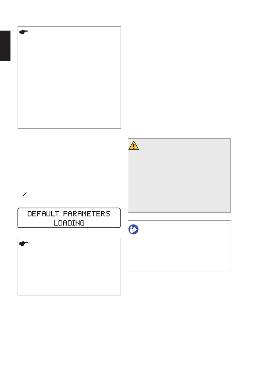
20
REMARQUES
Dans les canaux courbés, effectuez un mou-
fr
vement de brossage sur la paroi opposée à
la courbure canalaire. Avant de commencer le
mouvement de brossage, répétez les étapes
suivantes:
• nettoyez l’instrument dans le support Interim-Stand;
• irriguez le canal;
• vérifiez la perméabilité du canal à l’aide d’une
lime C-PILOT
• Si une lime de travail en mode réciproque est
bloquée dans le canal, essayez de la désengager à l’aide de précelles en tirant et tournant
délicatement la lime dans le sens horaire.
®
ISO taille10.
8.6. Paramètres par défaut
Pour rétablir les paramètres par défaut d’origine, veuillez
suivre les instructions de réinitialisation générale:
• Assurez-vous que le chargeur de batterie n’est pas
branché sur le secteur.
• Éteignez le dispositif.
• Appuyez simultanément sur la touche de confirmation
et la touche Marche/Arrêt. Le dispositif se met en
marche et l‘écran affiche le message suivant:
9. Nettoyage, désinfection et stérilisation
Avant et après chaque utilisation, inspectez les câbles
du chargeur de batterie, du micromoteur et de la pédale.
Contactez le centre SAV si le revêtement de l’un de ces
câbles présente des signes d’usure.
Nettoyez les câbles et les surfaces extérieures du dispositif avec de l’essuie-tout ou un chiffon en coton doux
légèrement imbibé d’une solution nettoyante et désinfectante sans aldéhyde (bactéricide et fongicide), par ex.
Mikrozid AF Liquid ou Minuten Spray Classic.
• DENTIRO
• TopActiv Wipes, ad-Arztbedarf GmbH, Allemagne.
• SprayActiv, ad-Arztbedarf GmbH, Allemagne.
• DY wipes, DENTSPLY, France.
®
Wipes, Oro Clean Chemie AG, Suisse.
MISES EN GARDE
• Pour désinfecter l’équipement et les câbles,
essuyez les surfaces à l’aide d’une lingette
ou d’un chiffon propre seulement légèrement
humidifié avec un désinfectant non agressif.
• N’utilisez pas de produits liquides ou en spray
directement sur l’équipement, notamment sur
l’écran.
• N’utilisez pas de solutions fortement concentrées en alcool pour désinfecter les surfaces.
REMARQUES
• Veuillez tenir compte du fait que tous les paramètres personnalisés, y compris ceux du programme Dr’s Choice, seront supprimés en cas
de restauration des paramètres par défaut.
• Les signaux sonores ne sont pas concernés:
les derniers paramètres utilisés avant l’arrêt du
dispositif sont conservés.
CONSULTEZ LE PROTOCOLE D’UTILISATION
Le contre-angle VDW 6:1 doit être nettoyé,
désinfecté et stérilisé avant sa première utilisation et après chaque utilisation ultérieure.
Consultez les instructions d’utilisation du
contre-angle VDW 6:1 concernant la procédure.
Page 93
21
Vérifiez que seules des méthodes de nettoyage/désinfection et de stérilisation validées sont appliquées, que
les appareils (désinfecteur, stérilisateur) font l’objet d’un
entretien et de contrôles périodiques et que les paramètres utilisés lors de chaque cycle sont ceux qui ont
été validés.
Veillez par ailleurs à toujours respecter la législation en
vigueur ainsi que les mesures relatives à l’hygiène applicables dans votre cabinet ou à la clinique. Cela concerne
également les directives sur l’élimination efficace des
prions.
Pour votre propre sécurité, portez toujours des gants, des
lunettes de protection et un masque chirurgical lorsque
vous manipulez des accessoires contaminés.
MISES EN GARDE
• Les câbles ne supportent pas une désinfection
thermique, ni une stérilisation thermique.
• L’utilisation de substances autres que celles
indiquées ci-dessus peut endommager le dispositif et les accessoires.
• Ne recourez pas à la stérilisation à air chaud,
à la stérilisation par irradiation ni à la stérilisation avec du formaldéhyde, de l’oxyde d’éthylène ou du plasma.
• Le boîtier en plastique n’est pas hermétique.
N’appliquez pas de produits liquides ou en
spray directement sur la console, notamment
sur l’écran ou à proximité des prises électriques.
Nous déclinons toute responsabilité en cas de non-respect de ces instructions ou d’utilisation de procédures
non homologuées pour préparer les accessoires en vue
de leur réutilisation.
9.1. Prétraitement (à réaliser après chaque utilisation)
Les résidus de pulpe et de dentine doivent être immédiatement éliminés des accessoires. Si nécessaire, utilisez
une brosse pour les nettoyer soigneusement (au plus
tard dans les 2heures qui suivent leur utilisation). Ne
laissez pas sécher les résidus sur les accessoires. Après
utilisation sur un patient, placez directement les accessoires dans un récipient rempli d’une solution nettoyante
et désinfectante appropriée (par ex. CIDEZYME®, ENZOL®
Enzymatic Detergent Solution, Johnson & Johnson Medical, 0,8% pendant 1minute à 2heures), afin de les nettoyer et de réaliser une désinfection préliminaire avant
leur stockage provisoire. Assurez-vous que les accessoires sont totalement immergés.
Lavez ensuite les accessoires à l’eau courante stérile et
déminéralisée ou dans une solution désinfectante pendant une minute à trois reprises au moins, afin d’éliminer
toute trace visible de contamination ou de résidus. Utilisez un désinfectant sans aldéhyde (les aldéhydes fixent
les taches de sang) dont l’efficacité est démontrée (par
ex. certification VAH/DGHM ou FDA, ou marquage CE). Il
doit également être adapté à la désinfection des accessoires et être compatible avec ceux-ci (cf. chapitre "9.7.
Résistance des matériaux").
Pour éliminer manuellement les traces de contamination
et de résidus, utilisez uniquement des brosses douces
et propres ou encore un chiffon doux ou une lingette
propre que vous réserverez exclusivement à cet usage.
N’utilisez pas de brosse métallique ou de paille de fer.
Contrôlez l’absence de traces de contamination visibles
ou de résidus. Renouvelez la procédure de prénettoyage
si nécessaire.
Veuillez noter que le désinfectant utilisé lors du prétraitement ne constitue qu’une simple protection pour éviter la
contamination pendant la manipulation; la désinfection
demeure indispensable une fois le nettoyage effectué. Le
prétraitement doit être réalisé de manière systématique.
fr
MISE EN GARDE
Les composants sont ni stérilisés ni désinfectés à leur livraison. Les étapes suivantes
doivent être réalisées avant la première utilisation et après chaque utilisation ultérieure.
MISE EN GARDE
N’utilisez pas de procédés automatiques ou
de bains à ultrasons pour nettoyer ou désinfecter les accessoires.
Page 94

22
9.2. Nettoyage et désinfection manuels
Lorsque vous sélectionnez des solutions de nettoyage et
de désinfection, vérifiez:
fr
• Qu’elles sont adaptées au nettoyage ou à la désinfection des accessoires.
• Que l’efficacité du désinfectant a été testée (par ex.,
certification VAH/DGHM ou FDA, ou marquage CE) et sa
compatibilité avec la solution de nettoyage démontrée.
• Que les produits chimiques utilisés sont compatibles
avec les accessoires (cf. chapitre "9.7. Résistance des
matériaux").
Les solutions à la fois nettoyantes et désinfectantes
peuvent être utilisées uniquement en cas de contamination légère des accessoires (pas de traces de contamination visibles).
Respectez les instructions fournies par les fabricants des
solutions nettoyantes et désinfectantes en matière de
concentration, de durée d’application et de rinçage.
Utilisez uniquement des solutions fraîchement préparées
avec de l’eau purifiée ou ayant une faible teneur en bactéries (< 10cfu/ml) et endotoxines (< 0,25EU/ml, par ex.
de l’eau purifiée (EP/EHP)), ainsi que de l’air filtré sans
huile pour le séchage.
Veillez à ce que les accessoires n’entrent pas en contact
direct entre eux.
Procédure étape par étape
Nettoyage
1) Placez les accessoires prénettoyés dans le bain
nettoyant pendant la durée d’exposition préconisée (par
ex. CIDEZYME
Johnson & Johnson Medical, 0,8% pendant 1 minute).
Vérifiez qu’ils sont suffisamment immergés (si nécessaire, utilisez une brosse douce pour un brossage délicat).
2) Retirez ensuite les accessoires du bain nettoyant et
rincez-les soigneusement à l’eau stérile et déminéralisée
pendant une minute à trois reprises au moins.
®
, ENZOL® Enzymatic Detergent Solutions,
Désinfection
3) Une fois les accessoires nettoyés et inspectés,
placez-les dans le bain désinfectant pendant la durée
d’exposition préconisée (par ex. Cidex OPA, Johnson
& Johnson Medical, 100 % pendant 20 minutes). Les
accessoires doivent être suffisamment immergés dans
la solution.
4) Retirez ensuite les accessoires du bain désinfectant
et rincez-les soigneusement à l’eau pendant une minute
à cinq reprises au moins.
5) Séchez tous les accessoires avec de l’air comprimé
filtré sans huile, puis laissez-les finir de sécher dans un
endroit propre pendant au moins 20minutes. Une fois les
accessoires séchés, inspectez-les et emballez-les dès
que possible (cf. les sections "9.3. Contrôle/Entretien" et
"9.4. Emballage").
6) Le contre-angle doit être lubrifié après le nettoyage
et la désinfection, mais avant la stérilisation. Respectez
les consignes fournies dans les instructions d’utilisation séparées du contre-angle VDW 6:1, ainsi que les
remarques suivantes:
• Lorsque vous lubrifiez le contre-angle, assurez-vous
que le lubrifiant ne pénètre pas dans le micromoteur.
• En cas de lubrification manuelle, utilisez de l’air comprimé (pendant env. 5 s) pour éliminer l’excès de
lubrifiant avant de remettre en place le contre-angle
sur le micromoteur. Calibrez le contre-angle après la
lubrification.
• En cas de lubrification automatique au moyen d’un
équipement d'entretien ou de lubrification, respectez
soigneusement les instructions du fabricant de l’équipement et vérifiez qu’il ne reste pas de lubrifiant en
excès sur le contre-angle.
• Ne lubrifiez en aucune circonstance le micromoteur.
Le lubrifiant peut perturber le bon fonctionnement du
micromoteur.
Page 95
23
9.3. Contrôle/Entretien
Contrôlez tous les accessoires après la procédure de nettoyage ou de nettoyage/désinfection. Éliminez immédiatement tout accessoire défectueux. Ces défauts peuvent
être:
• une déformation du plastique,
• des traces de corrosion,
• une décoloration du plastique.
Vous devez à nouveau nettoyer et désinfecter les acces-
soires encore contaminés. Aucun entretien n’est requis.
N’appliquez pas de lubrifiant sur les accessoires.
9.4. Emballage
Placez les accessoires dans des emballages de stérilisation jetables (emballages individuels à usage unique) qui
répondent aux critères suivants:
• conformes à la norme ISO11607-1,
• adaptés à la stérilisation à la vapeur (résistent à des
températures jusqu’à 142°C, perméabilité suffisante
à la vapeur).
9.5. Stérilisation
Utilisez uniquement les méthodes de stérilisation répertoriées ci-après. Toute autre procédure de stérilisation
est proscrite.
• Stérilisation à la vapeur
• Procédé de vide/pré-vide fractionné (au moins trois
cycles) ou procédé de gravitation avec un séchage
suffisant du produit (le produit doit être suffisamment
sec). La durée de séchage requise dépend directement
de paramètres qui relèvent de la seule responsabilité
de l’utilisateur (configuration du chargement, nombre
d’articles chargés et proximité des articles, état du
stérilisateur, etc.) et doit donc être déterminée par
l’utilisateur. Cette durée ne doit toutefois jamais être
inférieure à 20minutes. Le procédé de gravitation est
moins efficace, il doit être utilisé seulement s’il n’est
pas possible d’appliquer le procédé de vide fractionné.
• Stérilisateurs à vapeur d’eau conformes aux normes
EN13060 ou EN285, ANSI/AAMIST79.
• La validation de la stérilisation doit être réalisée
conformément à la norme ISO17665-1 (qualification
de l’installation et qualification opérationnelle (IQ et
OQ) et qualification de performance (QP) spécifique au
produit).
• Température maximale de stérilisation :
135 °C ; + tolérance conformément à la
norme ISO17665-1.
• Durée de stérilisation (durée d’exposition à la température de stérilisation): au moins 3minutes à 134°C.
fr
MISES EN GARDE
• Seul le contre-angle VDW 6:1 est adapté à
la stérilisation thermique. Référez-vous aux
instructions d’utilisation séparées relatives à
la stérilisation du contre-angle VDW 6:1 pour
mettre en œuvre un retraitement approprié.
• Seul le contre-angle VDW 6:1 peut faire
l’objet de procédures thermiques. Ne
soumettez aucun autre composant du
VDW.SILVER
dures.
• Ne placez jamais le micromoteur ou d’autres
accessoires dans le laveur-désinfecteur, un
autoclave ou un bain à ultrasons.
®
RECIPROC® à de telles procé-
MISES EN GARDE
• Les processus de stérilisation rapide ou de
stérilisation d’accessoires non emballés ne
sont pas autorisés.
• Ne recourez pas à la stérilisation à air chaud,
la stérilisation par irradiation ou la stérilisation
utilisant du formaldéhyde, de l’oxyde d’éthylène ou du plasma.
• Les exigences régionales doivent également
être respectées.
Page 96
24
9.6. Stockage
Après stérilisation, les instruments doivent être conservés dans leur emballage de stérilisation, au sec et à l’abri
fr
de la poussière.
9.7. Résistance des matériaux
Lorsque vous choisissez les produits de nettoyage et
de désinfection, assurez-vous qu’ils ne contiennent pas
l'une des substances suivantes:
• phénol,
• acides forts (pH <6) ou alcalins forts (pH >8),
• aldéhydes,
• substances anticorrosion (en particulier di- ou triéthanolamine),
• oxydants (peroxyde d’hydrogène, hypochlorite de
sodium à plus de 5%),
• solvants.
10. Entretien et dépannage
10.1. Entretien
Pour garantir une performance optimale de la batterie,
celle-ci doit être remplacée tous les 2ans par un centre
SAV agréé.
REMARQUE
Afin de garantir une durée de vie optimale
de la batterie, nous vous recommandons de
toujours travailler avec l’alimentation de la
batterie et de recharger celle-ci uniquement
lorsqu’elle est complètement épuisée.
Veuillez suivre les instructions détaillées au chapitre «9
Nettoyage, désinfection et stérilisation » pour garantir
une utilisation du dispositif conforme aux spécifications.
10.2. Dépannage
Si le dispositif ne fonctionne pas correctement, consultez
le tableau ci-après pour obtenir des informations sur les
causes possibles et trouver des solutions.
Ces informations sont pertinentes uniquement si vous
utilisez le VDW.SILVER
et/ou des pièces de rechange compatibles.
MISE EN GARDE
En cas de dysfonctionnement, débranchez
le dispositif pour éviter que l’utilisateur ou le
patient soit blessé.
®
RECIPROC® avec des accessoires
MISE EN GARDE
Le dispositif ne doit être ouvert en aucune circonstance. Il ne contient aucune pièce requérant un entretien.
Si les informations fournies ne vous permettent pas de
résoudre le problème, veuillez contacter le centre SAV
ou le service clientèle VDWGmbH. Les tâches d’entretien
et de réparation doivent être réalisées exclusivement par
des techniciens de maintenance formés par l’entreprise.
Page 97
25
Problème Cause Action
Le dispositif fume ou prend feu. Défaut du matériel.
Cessez immédiatement d’utiliser le dispositif, débranchez-le du secteur et contactez le centre SAV.
Le boîtier du chargeur de batterie est endommagé/cassé
La pièce à main est brûlante,
impossible de la tenir.
Le dispositif fuit (fuite d’électrolyte de la batterie)
Le dispositif ne s’allume pas. • Batterie déchargée.
L’appareil ne fonctionne pas
comme prévu.
L’écran ne fonctionne pas correctement : il est voilé, il clignote ou il est totalement noir
Défaut du matériel.
Défaut du matériel.
Défaut du boîtier de la
batterie.
• Chargeur de batterie
mal branché sur la
prise électrique.
• Chargeur de batterie
défectueux.
Mémoire de configuration corrompue.
Forte décharge électrostatique.
Cessez immédiatement d’utiliser le dispositif, débranchez-le du secteur et contactez le centre SAV.
Cessez immédiatement d’utiliser le dispositif, débranchez-le du secteur et contactez le centre SAV.
Cessez immédiatement d’utiliser le dispositif, débranchez-le du secteur et contactez le centre SAV.
• Rechargez la batterie.
• Contrôlez le branchement du chargeur de batterie
sur la prise électrique.
Restaurez les paramètres par défaut comme indiqué
au chapitre "8.6. Paramètres par défaut".
Cessez immédiatement d’utiliser le dispositif, débranchez-le du secteur et attendez 5minutes.
Branchez à nouveau le dispositif sur le secteur et
redémarrez-le.
Si le problème persiste, débranchez le dispositif du
secteur et contactez le centre SAV.
Risque d’incendie et d’électrocution.
Risque d’incendie et d’électrocution.
Risque d’incendie et d’électrocution.
Risque d’incendie et d’électrocution.
Risque de réaction allergique ou de toxicité.
fr
Page 98
26
Le micromoteur ne démarre
pas.
fr
La pédale ne démarre pas le
micromoteur.
• Câble du micromoteur mal branché.
• Contre-angle
VDW6:1 défectueux.
• Micromoteur défectueux.
• Forte décharge
électrostatique
• Pédale mal connectée.
• Pédale défectueuse.
• Vérifiez que le câble du micromoteur est correctement connecté au boîtier du micromoteur et à la
console.
• Vérifiez que le contre-angle fonctionne correctement et qu’il n’est pas bloqué : débranchez le
contre-angle du micromoteur, insérez une lime dans
le contre-angle et tournez la lime manuellement.
Si la lime tourne sans frottement important, le
contre-angle fonctionne correctement. Poursuivez
l’analyse pour identifier la cause première du problème. Dans le cas contraire, remplacez le contreangle.
• Vérifiez que le micromoteur fonctionne correcte-
ment: procédez au calibrage sans le contre-angle.
Si la procédure de calibrage échoue, réglez la
vitesse de rotation maximale sur la console, démarrez
le micromoteur et laissez-le tourner pendant au moins
5minutes. Procédez ensuite à nouveau au calibrage.
Si la procédure de calibrage échoue encore, contactez
le centre SAV.
Si la procédure de calibrage se déroule correctement, replacez le contre-angle sur le micromoteur et
relancez le calibrage. Si la procédure de calibrage
échoue encore, contactez le centre SAV.
• Une forte DES peut entraîner une défaillance tempo-
raire du moteur. Si les actions listées ci-dessus ne
permettent pas de résoudre le problème du moteur,
veuillez suivre les instructions de dépannage du cas
intitulé «L’écran ne fonctionne pas correctement».
• Vérifiez que la pédale est correctement connectée
au dispositif et appuyez à nouveau sur la pédale
pour démarrer le dispositif.
Si le micromoteur ne se met pas en marche,
démarrez-le en appuyant sur la touche de confirma-
tion pendant 1,5seconde. Si le micromoteur peut
être mis en marche de cette façon, remplacez la
pédale. Dans le cas contraire, contactez le centre SAV.
Page 99
27
Le chargeur de batterie ne
fonctionne pas correctement.
La batterie se décharge trop
rapidement.
CALIBRATION ERROR 1 (erreur
de calibrage 1).
CALIBRATION ERROR 2 (erreur
de calibrage 2).
Coordonnées du centre SAV:
VDW GmbH
Sales Service
Hoferstr. 1
81737 Munich
Allemagne
Téléphone: +49 89 62734555
Fax: +49 89 62734374
[email protected]
www. vdw-dental.com/service
Chargeur de batterie
défectueux.
• Batterie mal chargée.
• Batterie ou chargeur
de batterie défectueux.
Micromoteur mal
raccordé.
Le contre-angle
VDW6:1 est défectueux, il présente une
résistance excessive.
Ne remplacez pas le chargeur de batterie fourni
par un autre type d’alimentation.
• Vérifiez que le connecteur est correctement branché
sur le boîtier du chargeur de batterie.
• Vérifiez que le chargeur de batterie est correctement
branché sur la prise électrique et sur la console.
• Contactez le centre SAV pour un remplacement.
• Chargez entièrement la batterie, en tenant compte
de la diode de la batterie. Cf. chapitre "8.2.5. Batterie".
• Contactez le centre SAV pour un remplacement.
Vérifiez la connexion du micromoteur et lancez à nouveau la procédure de calibrage.
Si le problème persiste, suivez les instructions
de dépannage du cas intitulé « Le micromoteur ne
démarre pas».
Suivez les instructions de dépannage du cas intitulé
«Le micromoteur ne démarre pas».
fr
Page 100

28
11. Notification d’un événement
imprévu
fr
En cas d’incident lié directement ou indirectement au
dispositif, veuillez immédiatement signaler celui-ci au
fabricant ainsi qu’aux autorités compétentes de votre
pays et du pays où réside le patient (en cas de pays différent).
Par e-mail:
MunichDEU-VDW-ComplaintDepartment@vdw-dental.
com/ [email protected]
Par fax:
+49 89 62734 - 379
Par courrier:
VDW GmbH
Complaint Department
Bayerwaldstr. 15
81737 Munich
Allemagne
12. Mise au rebut des pièces usagées
Le présent dispositif ne doit pas être mis au rebut avec
les déchets ménagers. Si vous souhaitez vous défaire
définitivement du dispositif, veuillez respecter les réglementations nationales concernant la mise au rebut des
équipements électriques. Pour plus d’informations,
contactez directement VDWGmbH.
REMARQUES
Respectez les instructions du mode d’emploi
du fabricant pour l’élimination des instruments endodontiques.
En vue de leur mise au rebut, le dispositif et ses accessoires doivent avoir été décontaminés et entièrement
retraités, conformément aux instructions détaillées au
chapitre «9 Nettoyage, désinfection et stérilisation».
Les Déchets d’Équipements Électriques et Électroniques
appartenant aux clients basés dans l’Union Européenne
peuvent être expédiés à VDW à des fins de recyclage,
conformément à la directive DEEE. Le coût du recyclage,
à l’exception des frais d’expédition, sont pris en charge
par VDW.
 Loading...