

Page 1
VIP 10
VIP 1000
User Guide
Page 2

Copyright
This user guide is the intellectual property of VCS and is protected by copyright.
All rights reserved. No part of this document may be reproduced or transmitted
for any purpose, by whatever means, electronic or mechanical, without the
express written permission of VCS.
Release: March 2004 (Software Version 2.0)
© 2004, VCS Video Communication Systems AG
Note
This user guide has been compiled with great care and the information it contains
has been thoroughly verified. The text was complete and correct at the time of
printing. Due to further product development, the contents of the user guide may
change without prior notice. VCS accepts no liability for damages resultin g
directly or indirectly from errors, omissions or discrepancies between the user
guide and the product described.
Trademarks
All hardware and software product names used in this document are likely to be
registered trade marks and must be treated accordingly.
Page 3

Contents
Contents 0
Kapitel 1 Contents
Kapitel 1 Preface
About this user guide. . . . . . . . . . . . . . . . . . . . . . . . . . . . . . . . . . . 7
Conventions. . . . . . . . . . . . . . . . . . . . . . . . . . . . . . . . . . . . . . . . . . 7
Intended use . . . . . . . . . . . . . . . . . . . . . . . . . . . . . . . . . . . . . . . . . 8
EU guidelines. . . . . . . . . . . . . . . . . . . . . . . . . . . . . . . . . . . . . . . . . 8
Rating plate . . . . . . . . . . . . . . . . . . . . . . . . . . . . . . . . . . . . . . . . . . 8
Kapitel 2 Safety Information
Electrical shock hazard . . . . . . . . . . . . . . . . . . . . . . . . . . . . . . . . . 9
Installation and operation. . . . . . . . . . . . . . . . . . . . . . . . . . . . . . . 10
Maintenance and repair. . . . . . . . . . . . . . . . . . . . . . . . . . . . . . . . 10
Kapitel 3 Product Description
Supplied components . . . . . . . . . . . . . . . . . . . . . . . . . . . . . . . . . 11
System requirements for setup . . . . . . . . . . . . . . . . . . . . . . . . . . 11
Configuration requirements . . . . . . . . . . . . . . . . . . . . . . . . . . . . . 11
Operational requirements . . . . . . . . . . . . . . . . . . . . . . . . . . . . . . 12
Overview of functions . . . . . . . . . . . . . . . . . . . . . . . . . . . . . . . . . 12
VIP 10 and VIP 1000 Receiver Connections . . . . . . . . . . . . . . . 15
VIP 1000 Transmitter Connections . . . . . . . . . . . . . . . . . . . . . . . 16
Kapitel 4 Installation
Installing the unit . . . . . . . . . . . . . . . . . . . . . . . . . . . . . . . . . . . . . 17
Connections. . . . . . . . . . . . . . . . . . . . . . . . . . . . . . . . . . . . . . . . . 18
Switching on/off . . . . . . . . . . . . . . . . . . . . . . . . . . . . . . . . . . . . . . 20
Setup using terminal software . . . . . . . . . . . . . . . . . . . . . . . . . . . 21
Kapitel 5 Configuration using a Web Browser
Establishing the connection. . . . . . . . . . . . . . . . . . . . . . . . . . . . . 25
Choosing the configuration mode . . . . . . . . . . . . . . . . . . . . . . . . 28
Configuration with the Installation Wizard . . . . . . . . . . . . . . . . . . 29
Configuration in Expert Mode . . . . . . . . . . . . . . . . . . . . . . . . . . . 32
VIP 10/1000 3
Page 4

Contents
Kapitel 6 Configuring the Transmitter
Basics . . . . . . . . . . . . . . . . . . . . . . . . . . . . . . . . . . . . . . . . . . . . . 35
Unit identification. . . . . . . . . . . . . . . . . . . . . . . . . . . . . . . . . . . . . 35
Password settings. . . . . . . . . . . . . . . . . . . . . . . . . . . . . . . . . . . . 36
Language selection . . . . . . . . . . . . . . . . . . . . . . . . . . . . . . . . . . . 37
Date and time . . . . . . . . . . . . . . . . . . . . . . . . . . . . . . . . . . . . . . . 37
Timer server . . . . . . . . . . . . . . . . . . . . . . . . . . . . . . . . . . . . . . . . 38
Camera name . . . . . . . . . . . . . . . . . . . . . . . . . . . . . . . . . . . . . . . 38
Display stamping. . . . . . . . . . . . . . . . . . . . . . . . . . . . . . . . . . . . . 39
MPEG-2 Encoder configuration (VIP 1000 only). . . . . . . . . . . . . 40
MPEG-4 Encoder configuration. . . . . . . . . . . . . . . . . . . . . . . . . . 43
Video input settings. . . . . . . . . . . . . . . . . . . . . . . . . . . . . . . . . . . 46
Audio configuration . . . . . . . . . . . . . . . . . . . . . . . . . . . . . . . . . . . 46
Alarm sources . . . . . . . . . . . . . . . . . . . . . . . . . . . . . . . . . . . . . . . 47
Alarm connections. . . . . . . . . . . . . . . . . . . . . . . . . . . . . . . . . . . . 48
Motion detector . . . . . . . . . . . . . . . . . . . . . . . . . . . . . . . . . . . . . . 50
Relay action / Relay operation . . . . . . . . . . . . . . . . . . . . . . . . . . 53
COM1 serial data port / COM1 interface settings . . . . . . . . . . . . 55
Network settings . . . . . . . . . . . . . . . . . . . . . . . . . . . . . . . . . . . . . 56
Multicast settings. . . . . . . . . . . . . . . . . . . . . . . . . . . . . . . . . . . . . 59
Version information . . . . . . . . . . . . . . . . . . . . . . . . . . . . . . . . . . . 61
Livepage configuration . . . . . . . . . . . . . . . . . . . . . . . . . . . . . . . . 62
Software update . . . . . . . . . . . . . . . . . . . . . . . . . . . . . . . . . . . . . 64
Function test . . . . . . . . . . . . . . . . . . . . . . . . . . . . . . . . . . . . . . . . 66
Kapitel 7 Configuring the Receiver
Basics . . . . . . . . . . . . . . . . . . . . . . . . . . . . . . . . . . . . . . . . . . . . . 67
Unit identification. . . . . . . . . . . . . . . . . . . . . . . . . . . . . . . . . . . . . 67
Unit password . . . . . . . . . . . . . . . . . . . . . . . . . . . . . . . . . . . . . . . 68
Language selection . . . . . . . . . . . . . . . . . . . . . . . . . . . . . . . . . . . 68
Date and time . . . . . . . . . . . . . . . . . . . . . . . . . . . . . . . . . . . . . . . 69
Timer server . . . . . . . . . . . . . . . . . . . . . . . . . . . . . . . . . . . . . . . . 70
Monitor settings. . . . . . . . . . . . . . . . . . . . . . . . . . . . . . . . . . . . . . 70
Audio configuration . . . . . . . . . . . . . . . . . . . . . . . . . . . . . . . . . . . 71
Alarm sources . . . . . . . . . . . . . . . . . . . . . . . . . . . . . . . . . . . . . . . 71
Alarm connections. . . . . . . . . . . . . . . . . . . . . . . . . . . . . . . . . . . . 72
Relay action / Relay operation . . . . . . . . . . . . . . . . . . . . . . . . . . 73
COM1 serial data port / COM1 interface settings . . . . . . . . . . . . 75
Network settings . . . . . . . . . . . . . . . . . . . . . . . . . . . . . . . . . . . . . 76
Version information . . . . . . . . . . . . . . . . . . . . . . . . . . . . . . . . . . . 78
Software update . . . . . . . . . . . . . . . . . . . . . . . . . . . . . . . . . . . . . 79
4 VIP 10/1000
Page 5

Function test . . . . . . . . . . . . . . . . . . . . . . . . . . . . . . . . . . . . . . . . 81
Kapitel 8 Transmitter Operation
Operation with Microsoft Internet Explorer . . . . . . . . . . . . . . . . . 83
The Livepage. . . . . . . . . . . . . . . . . . . . . . . . . . . . . . . . . . . . . . . . 83
Saving snapshots . . . . . . . . . . . . . . . . . . . . . . . . . . . . . . . . . . . . 87
Recording video sequences . . . . . . . . . . . . . . . . . . . . . . . . . . . . 88
Kapitel 9 Receiver Operation
Operation with Microsoft Internet Explorer . . . . . . . . . . . . . . . . . 89
The Decoder connection page . . . . . . . . . . . . . . . . . . . . . . . . . . . 89
Connection between the receiver and transmitter . . . . . . . . . . . . 90
Kapitel 10 Hardware Connections
Hardware connections between VIP units. . . . . . . . . . . . . . . . . . 91
Establishing the connection. . . . . . . . . . . . . . . . . . . . . . . . . . . . . 91
Closing the connection . . . . . . . . . . . . . . . . . . . . . . . . . . . . . . . . 93
Kapitel 11 Operation with Decoder Software
Operation with VIDOS . . . . . . . . . . . . . . . . . . . . . . . . . . . . . . . . . 95
Kapitel 12 Maintenance and Upgrades
Testing the network connection. . . . . . . . . . . . . . . . . . . . . . . . . . 97
Device reset. . . . . . . . . . . . . . . . . . . . . . . . . . . . . . . . . . . . . . . . . 97
Repairs . . . . . . . . . . . . . . . . . . . . . . . . . . . . . . . . . . . . . . . . . . . . 98
Transfer and disposal . . . . . . . . . . . . . . . . . . . . . . . . . . . . . . . . . 98
Contents
Kapitel 13 Appendix
Troubleshooting. . . . . . . . . . . . . . . . . . . . . . . . . . . . . . . . . . . . . . 99
LEDs . . . . . . . . . . . . . . . . . . . . . . . . . . . . . . . . . . . . . . . . . . . . . 101
RS232/485 interface . . . . . . . . . . . . . . . . . . . . . . . . . . . . . . . . . 102
Connection jacks . . . . . . . . . . . . . . . . . . . . . . . . . . . . . . . . . . . . 104
Glossary. . . . . . . . . . . . . . . . . . . . . . . . . . . . . . . . . . . . . . . . . . . 105
VIP 10 Specifications . . . . . . . . . . . . . . . . . . . . . . . . . . . . . . . . . 108
VIP 1000 Specifications. . . . . . . . . . . . . . . . . . . . . . . . . . . . . . . 110
Kapitel 14 Index
VIP 10/1000 5
Page 6

6 VIP 10/1000
Page 7

Preface 1
About this user guide
This user guide is intended for persons responsible for the installation and
operation of the VIP 10 or the VIP 1000 network video servers. International,
national and any regional regulations regarding electrical systems must be
adhered to at all times. The user manual describes the installation and operation
of the unit.
Conventions
Symbols and notation
The following symbols and notation highlight important situations and
information.
Warning!
This symbol indicates that failure to follow the safety instructions described
may endanger persons and cause damage to the unit or other equipment.
It is associated with immediate, direct hazards.
Note
This symbol indicates tips and information for easier, more convenient use
of the unit.
Designation of the units
This user guide describes the installation and operation of the VIP 10 and
VIP 1000 network video servers. In most cases, unit installation and operation is
the same, and the description and instructions given apply to both. Where this
applies, both devices are referred to by the common designation "VIP". Steps that
apply to only one unit are clearly identified as such. In these cases, the relevant
unit is referred to by its full name.
VIP 10 / VIP 1000 7
Page 8

Preface Chapter 1
Intended use
The VIP 10 and VIP 1000 network video servers transmit video, audio and control
signals over data networks (such as Ethernet LANs and the Internet). They are
designed for use in CCTV systems. By incorporating external alarm devices,
various functions can be triggered automatically. Other applications are not
authorized.
For questions regarding the use of the units that are not answered in this user
guide, please contact your local dealer or:
VCS Video Communication Systems AG
Forchheimer Strasse 4
90425 Nuremberg, Germany
Phone: +49 (0)911 9 34 56-0
Fax: +49 (0)911 9 34 56-66
EU guidelines
Both the VIP 10 and VIP 1000 network video servers comply with the
specifications of EU Directives 89/336 (Electromagnetic Compatibility) and
73/23, amended by 93/68 (Low Voltage Directive).
Rating plate
For exact identification of the unit, the model and serial number are inscribed on
the rating plate on the bottom of the housing. Please note this information before
starting installation, so that you have it ready if you need to ask for assistance or
order spare parts.
8 VIP 10 / VIP 1000
Page 9

Safety Information 2
Electrical shock hazard
] Never attempt to connect the unit to any power n etwork other than t he type for
which it was intended.
] Use only the power supply provided.
] Never open the casing!
] If a fault occurs, disconnect the power supply unit from the mains supply and
from all other devices.
] Install the unit and power supply only in dry, weather-protected areas.
] If safe operation of the unit cannot be guaranteed, remove it from service and
secure it to prevent unauthorized start-up. Safe operation can no longer be
guaranteed, for example,
– if there is visible damage to the unit or power cables,
– if the unit no longer works properly,
– if the unit has been exposed to rain or moisture,
– if foreign matter has infiltrated the unit,
– after long storage under adverse conditions or
– after exposure to higher than normal stress during transport.
In such cases, have the unit checked by VCS.
VIP 10 / VIP 1000 9
Page 10

Safety Information Chapter 2
Installation and operation
] Relevant electrical codes and guidelines must be complied with at all times
during installation.
] Before installing or operating the unit, make sure you have read and
understood the documentation for the other equipment connected to the
system, such as cameras. There you will find important safety instructions and
information about authorised use.
] Perform only the installation tasks and operating steps described in this
manual. Additional actions may lead to personal injuries, property damage or
damage to the equipment.
Maintenance and repair
] Never open the casing of the VIP. The unit does not contain parts that you can
repair or replace.
] Never open the housing of the power supply unit. The power supply unit does
not contain parts that you can repair or replace.
] Ensure that all maintenance or repair work is performed exclusively by
qualified personnel (electrical technicians).
10 VIP 10 / VIP 1000
Page 11

Product Description 3
Supplied components
] Network video server, model VIP 10 or VIP 1000, including plug-in mains
adapter
] RS232 null modem cable
] Quick start guide “First Steps” in English/German
] CD with software and user guides
System requirements for setup
] Computer with Microsoft Windows 98/2000/XP operating system and network
access and
] Microsoft Internet Explorer (version 5.5 or higher) or
a free serial port and terminal software
Configuration requirements
] Computer with Microsoft Windows 98/2000/XP operating system and network
access and
] Microsoft Internet Explorer (version 5.5 or later) or decoder software, such as
VIDOS from VCS
Note
Make sure the graphic card is set to 16 or 32 bit color depth and Microsoft's
Virtual Machine is installed on your computer.
VIP 10 / VIP 1000 11
Page 12

Product Description Chapter 3
Operational requirements
] Computer with Microsoft Windows 98/2000/XP operating system and network
access and
] Microsoft Internet Explorer (version 5.5 or later) or decoder software, such as
VIDOS from VCS
or
] VIP acting as the receiver and video monitor
or
] VideoJet from VCS acting as the receiver and video monitor
Note
Make sure the graphic card for receiving on the computer monitor is set to
16 or 32 bit color depth and Microsoft's Virtual Machine is installed on the
computer.
Overview of functions
Network video server
The VIP module is an ultra-compact network video server. Its primary function is
to encode and decode video, audio and control data for transmission over an IP
network. The module is particularly well suited to adapting analog cameras for IP
communication and for remote access to digital video recorders and multiplexers.
About the size and shape of a cigarette packet, it can be integrated into small
enclosures without difficulty. The use of existing networks means that integration
with CCTV systems or local networks is quick and easy.
Two units, a VIP as the transmitter and another VIP as the receiver, can form a
stand-alone system for data transfer without a PC. The system can be expanded
to include additional transmitters and receivers so that video images from one
transmitter can be received simultaneously on a number of receivers.
Receiver
VIP or VideoJet units from VCS can be used as receivers. Computers with
decoding software such as VIDOS from VCS or Microsoft Internet Explorer can
also be used as receivers.
12 VIP 10 / VIP 1000
Page 13

Chapter 3 Product Description
Video encoding
The VIP 10 works with the MPEG-4 video compression standard. The VIP 1000
works with the MPEG-2 and MPEG-4 standards.
Due to the efficiency of e ncoding usi ng MPEG-2, t he data r ate remains lo w even
with high image quality and can also be adapted to local conditions within wide
limits. MPEG-4 enables data transfer at narrow bandwidth – via Internet for
example.
Dual encoding
Dual encoding allows the incoming data stream to be encoded simultaneously
according to two different, individually customizable profiles. This creates two
data streams that can serve different purposes, for example one for local
recording and one optimized for transmission via the LAN.
Multicast
In suitably configured networks, the multicast function enables simultaneous, real
time video transmission to multiple receivers. The prerequisite for this is that the
UDP and IGMP protocols be implemented on the network.
Remote control
The VIP can remotely control external devices, such as pan and tilt heads or
motorized zoom lenses, by transmitting control data via its bidirectional serial
interface. This interface can also be used to transmit transparent data.
Configuration
The VIP can be configured using a browser on the local network (Intranet) or via
Internet.
Firmware updates and fast loading of device configurations are possible in the
same way.
Recording and playback
You can save the video images provided by the unit as a file on the hard drive of
your computer. The video sequences are stored in MPEG format and can be
replayed with the VCS MPEG Viewer included with the package.
VIP 10 / VIP 1000 13
Page 14

Product Description Chapter 3
Snapshots
Individual video frames (snapshots) can be called up as JPEG images by the VIP,
stored on the hard drive or displayed in a separate browser window.
Backup
Backups of video sequences can be made to the hard drive from the Video
Livepage with a simple click of the mouse.
Summary
The main functions of the VIP are:
] Video, audio and data transmission over IP data networks
] Simultaneous dual encoding with two independently defined profiles
] Multicast function for simultaneous picture transmission to multiple receivers
] Analog BNC composite video input FBAS (PAL/NTSC) (transmitter)
] Analog BNC composite video output FBAS (PAL/NTSC) (receiver)
] A bidirectional audio input/output (mono)
] Video and audio encoding using the MPEG-4/G.711 and MPEG-2 (VIP 1000
only) international standards
] Integrated Ethernet interface (10/100 Base-T)
] A transparent bidirectional data channel using a serial interface, type
RS232/485
] Remote control of all built-in functions via TCP/IP
]
Password protection to prevent unauthorized connection or configuration changes
] Relay input for an external sensor (such as a door contact)
] Relay output for switching external devices (such as lights or audible alarms)
] Event-driven, automatic connection (for example when switching on and
when alarms are activated)
] Fast, convenient configuration using a Web browser
] Firmware update using flash memory
] Convenient upload of configuration data
14 VIP 10 / VIP 1000
Page 15
Chapter 3 Product Description
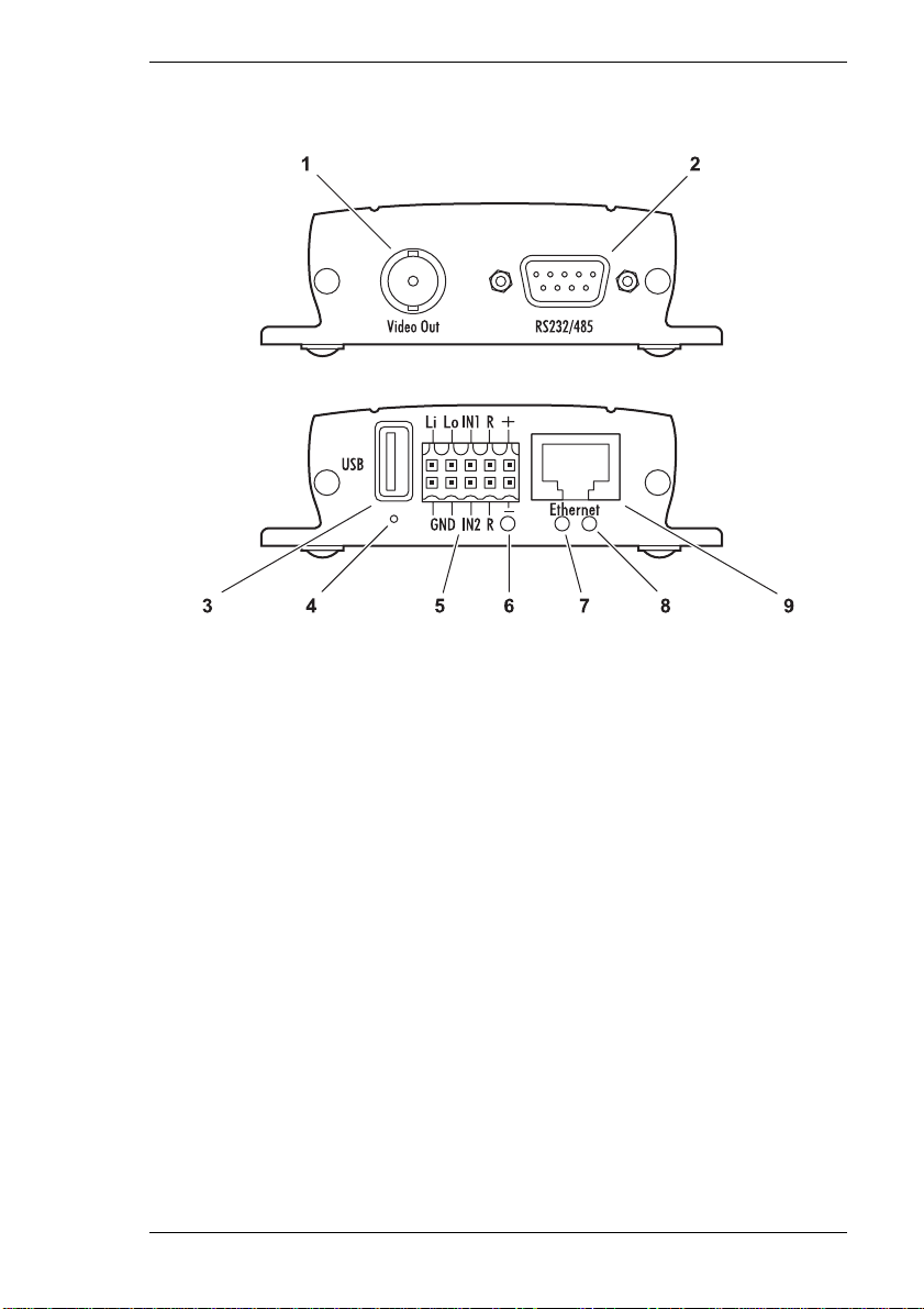
VIP 10 and VIP 1000 Receiver Connections
1 BNC jack: Video In (transmitter) or Video Out (receiver),
for connecting a video source or an analog video monitor
2RS232/485 serial interface
9-pin Sub D socket (male) for transmitting control data and
configuration with terminal software
3USB interface
for future expansion of the recording function
4 Reset button for restoring the default settings
5 Terminal block (audio, alarms, relay and power supply)
6 Operating status LED
yellow, lights up when the device is ready for operation
7 Network connection LED
green, lights up when the device is connected to the network
8 Data transfer LED
flashes yellow when data is transmitted over the network
9 RJ45 jack for Ethernet
for connecting to the network
VIP 10 / VIP 1000 15
Page 16
Product Description Chapter 3
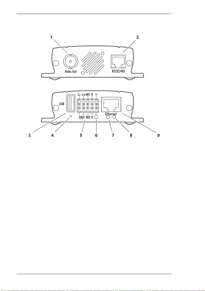
VIP 1000 Transmitter Connections
1 BNC jack Video In
for connecting a video source
2 RJ45 jack for RS232/485
for transmitting control data and
configuration with terminal software
3USB interface
for future expansion of the recording function
4 Reset button for restoring the default settings
5 Terminal block (audio, alarms, relay and power supply)
6 Operating status LED
yellow, lights up when the device is ready for operation
7 Network connection LED
green, lights up when the device is connected to the network
8 Data transfer LED
flashes yellow when data is transmitted over the network
9 RJ45 jack for Ethernet
for connecting to the network
16 VIP 10 / VIP 1000
Page 17

Installation 4
Installing the unit
With its ultra-compact dimensions, the VIP is particularly well suited for
installation in cabinets.
Warning!
The unit is intended for use indoors or in a protective enclosure. Select a
suitable location for installation where the equipment is not subject to
extreme temperatures or humidity. The ambient temperature must lie
between 0 and +50 °C. The relative humidity should not exceed 80%.
The unit generates heat during operation. Ensure that there is adequate
ventilation and also that there is enough clearance between the unit and
heat-sensitive objects or equipment.
Make sure the following conditions for installation are complied with:
] Do not mount the unit close to heaters or other heat sources. Avoid locations
subject to direct sunlight.
] Allow sufficient space for running cables.
] Ensure that the unit has adequate ventilation.
] Use only the cables supplied for connections or appropriate cables, which are
also shielded against electromagnetic interference.
] Position and run all cables so that they are protected from damage, and
provide strain relief where needed.
VIP 10 / VIP 1000 17
Page 18

Installation Chapter 4
Connections
Camera/monitor
Depending on the device used, you can connect a video source (transmitter) or
a monitor (receiver). All cameras and video sources that generate a standard PAL
or NTSC signal and all monitors compatible with PAL or NTSC standards can be
used for this purpose.
– Connect the camera or another video source using a video cable (75 Ohms,
BNC plug) to the Video In BNC jack of the transmitter.
or
– Connect the video monitor using a video cable (75 Ohms, BNC plug) to the
Video Out BNC jack of the receiver.
Data interface
The bidirectional data interface is used to control equipment connected to the VIP
unit, such as a dome camera with a motorized lens.
The RS232/485 connection supports RS232, RS422 and RS485 communication
standards.
The selection of controllable devices is growing constantly. The manufacturers of
this equipment can provide specific information on installation and control .
Warning!
Make use of the device documentation when installing and operating a
device that you want to control using the system. It contains important
safety instructions and information about authorized use.
Note
A video connection is necessary to transmit transparent data.
Network
You can connect the VIP directly to a 10/100 Base-T network or via a hub. Use a
standard UTP Category 5 cable with RJ45 connectors for this.
– Connect the unit to the network using the Ethernet jack.
18 VIP 10 / VIP 1000
Page 19

Chapter 4 Installation
Alarm inputs
The VIP has two alarm inputs on the orange terminal block. The alarm inputs are
used to transfer signals from external alarm devices, such as door contacts or
sensors. Given the appropriate configuration, an alarm device can, for example,
trigger automatic connection between the VIP and a remote location. A voltage
free normally open contact or switch can be used as an actuator.
Note
It is preferable to use an actuator with a bounce-free contact system.
– Connect the leads to the appropriate terminals on the orange terminal block
and check that the connection is secure.
Relay output
The VIP has a relay output for switching external devices, such as lights or
audible alarms. This relay output can be activated manually if there is an active
connection with the VIP. Moreover, the output can be configured to activate
audible alarms or other devices as a response to an alarm signal. The relay
output is also located on the orange terminal block.
Warning!
The maximum rating of the relay contact is 30 V and 1 A.
– Connect the leads to the appropriate terminals on the orange terminal block
and check that the connection is secure.
Microphone/loudspeaker
The connection for the microphone/loudspeaker is also on the orange terminal
block.
The bidirectional audio signals are transmitted simultaneously with the video
signals. This can be used for example to operate a loudspeaker or door intercom
at the target location.
– Connect a line level audio source to the appropriate terminals on the orang e
terminal block of the transmitter and check that the connection is secure.
– Connect a loudspeaker to the appropriate terminals on the orange terminal
block of the receiver and check that the connection is secure.
VIP 10 / VIP 1000 19
Page 20

Installation Chapter 4
Switching on/off
Power connection
A plug-in mains adapter is included with the VIP package. The VIP does not have
a mains switch. The unit is ready for operation as soon as it is connected to the
mains supply.
Warning!
Use only the plug-in mains adapter provided for operation of the VIP. Where
necessary, take appropriate measures to ensure that the mains supply is
protected against voltage surges, spikes or brownouts.
Warning!
Do not connect the VIP to the power source until all the other connections
have been made.
– Connect the cable of the mains adapter to the orange terminal block of the VIP.
– Plug the mains adapter into a fused power socket. The unit is ready for
operation as soon as the "operating status" LED stops flashing red during
start-up and becomes yellow.
If the network connection is in order, the yellow "network connection" LED is also
lit. The flashing orange "data transmission" LED indicates data traffic on the
network.
20 VIP 10 / VIP 1000
Page 21

Chapter 4 Installation
Setup using terminal software
Data terminal
You can connect a data terminal to the VIP for setup and local control. The data
terminal consists of a computer with terminal software. Use the serial null-modem
cable included in the package supplied to make the connection.
For example, HyperTerminal, a communications utility included with Microsoft
Windows, can be used as the terminal program.
Note
Information on installing and using HyperTerminal can be found in the user
guides or online help for Microsoft Windows.
– Before working with the terminal program, disconnect the VIP from the data
network.
– Connect the RS232/485 Sub D connector of the VIP to an available serial port
on the computer.
Configuring the terminal
To establish communication between the terminal program and the VIP, the
transmission parameters must be correctly defined. Set the following values in th e
terminal program:
] 19,200 Bit/s
] 8 data bits
] No parity check
] 1 stop bit
] No protocol
Command entry
After the connection has been established, you must log on to the VIP. You can
then access the main menu. You can call up additional submenus and functions
using the on-screen commands.
] If necessary, turn off the local echo so that entered values are not repeated on
the screen display.
VIP 10 / VIP 1000 21
Page 22
Installation Chapter 4
] Enter only one command at a time.
] After entering a value (such as an IP address), re-check the entry before
pressing the Enter key to send the data to the VIP.
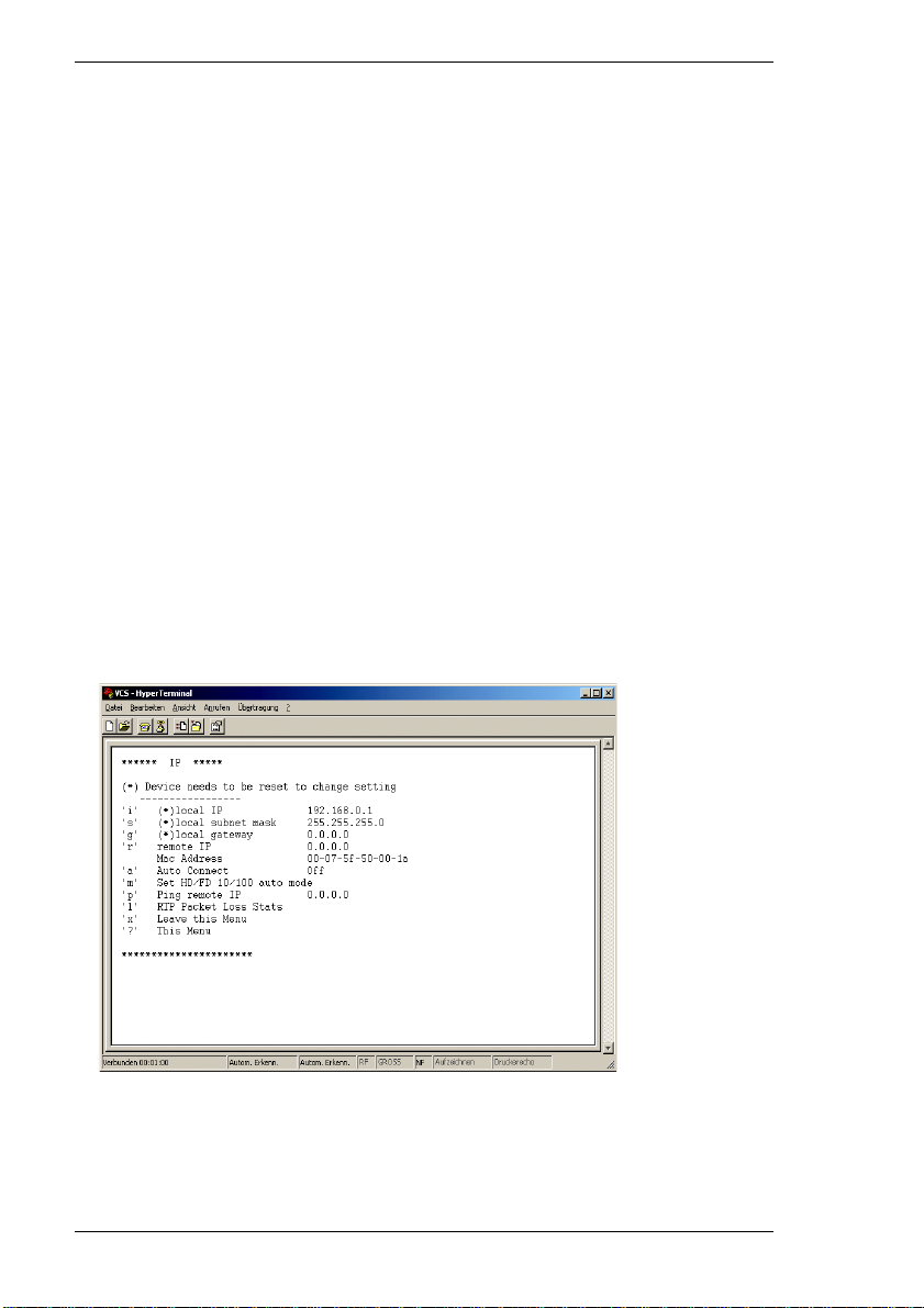
Assigning an IP address
To operate the VIP on your network, you must assign it an IP address that is
recognized by the network.
The following default address has been pre-set at the factory:
Transmitter: 192.168.0.1
Receiver: 192.168.0.2
– Start up a terminal program such as HyperTerminal.
– Enter the user name service. The main menu will be displayed.
– Enter I to open the IP menu.
– Enter i. The current IP address will be displayed, and you will be requested to
enter a new IP address.
– Enter the desired IP address and press Enter. The new IP address will be
displayed and becomes effective following a restart.
22 VIP 10 / VIP 1000
Page 23

Chapter 4 Installation
Additional parameters
Using the terminal program, you can check other basic parameters and modify
them where necessary. Use the on-screen commands displayed in the various
submenus for this purpose.
VIP 10 / VIP 1000 23
Page 24

24 VIP 10 / VIP 1000
Page 25

Configuration using a Web Browser 5
Establishing the connection
The integrated HTTP server allows the unit to be configured over the network
using a Web browser. This option offers considerably more possibilities and is
more convenient than configuration using terminal software. It also allows live
video images to be displayed.
Note
Before the computer can decode live video images, the appropriate, special
ActiveX Control must be installed. The latest version of the ActiveX Control
is on the accompanying software CD. It is also available from VCS
Customer Service or as an Internet download at www.vcs.com.
Instructions for using the Web browser can be found in its online help.
System requirements
] Microsoft Internet Explorer (version 5.5 or higher)
] Monitor resolution 1024 × 768 pixels
] Network access (intranet or Internet)
Note
Make sure the graphic card is set to 16 or 32 bit color depth and Microsoft's
Virtual Machine is installed on your computer.
MPEG decoder installation
If no video images are displayed when MPEG-2 or MPEG-4 is selected, it may be
necessary to install a current MPEG decoder. This software is on the VCS CD
included with the package.
– Insert the CD into the CD-ROM drive of the computer. The CD should start
automatically. If the CD does not start automatically, open the root directory of
the CD in Windows Explorer and double click MPEGAx.exe.
– Follow the instructions on the screen.
VIP 10 / VIP 1000 25
Page 26
Configuration using a Web Browser Chapter 5
Establishing the connection
The VIP must be assigned a valid IP address for your network, before it can be
operated in your network environment.
The following default address has been pre-set at the factory:
Transmitter: 192.168.0.1
Receiver: 192.168.0.2
– Start the Web Browser.
– Enter the IP address of the VIP as the URL. The VIP home page will be shown
in the browser.
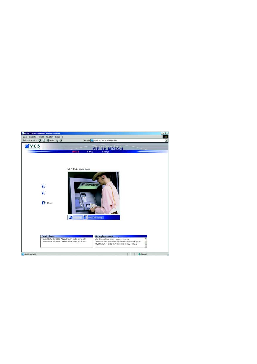
If the unit is a transmitter, the home page will be the Livepage (which shows the
live video image).
26 VIP 10 / VIP 1000
Page 27
Chapter 5 Configuration using a Web Browser
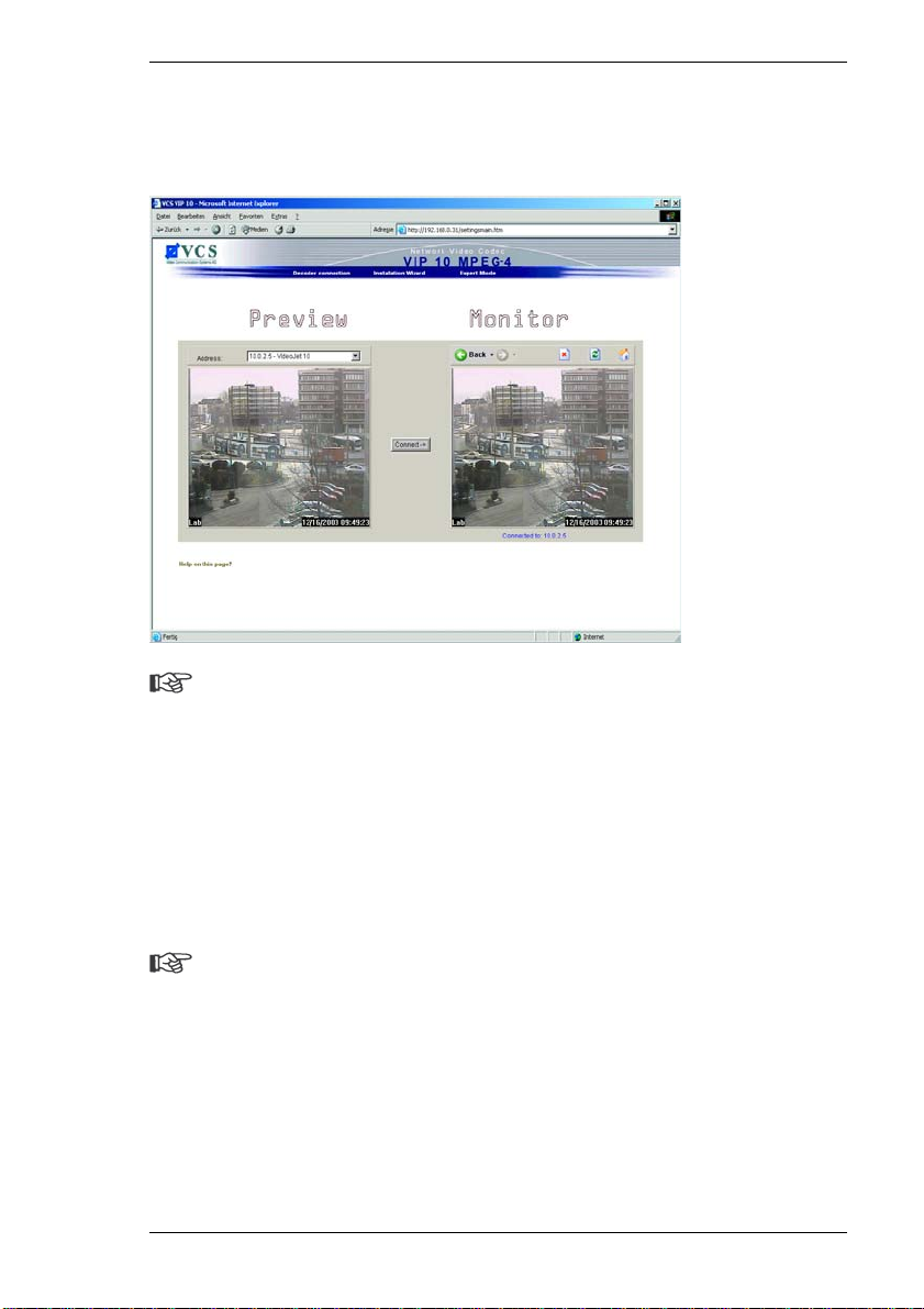
The Con nection page will be displayed as the home page for a receiver. It shows
a snapshot from the video source for the transmitter currently connected, and the
unit searches the network automatically for available transmitters.
Note
If the connection cannot be established, the unit selected may already be
in communication with another remote station. Depending upon the
network configuration and the individual units, a transmitter can serve up to
five receivers simultaneously.
VIP password protection
If the VIP is password-protected agai nst unauthorized access, a dialog box
requesting the password will appear first.
Note
Configuration work can only be performed on a password-protected VIP
unit if the user logs on under the Service user name.
– Enter the user name and password in the appropriate fields.
– Click OK. If the password is correct, the VIP home page will open.
VIP 10 / VIP 1000 27
Page 28

Configuration using a Web Browser Chapter 5
Choosing the configuration mode
There are two options to configure the VIP or to check the current setup:
] the Installation Wizard and
] Expert Mode.
All settings are stored in the VIP memory, and they are preserved even if the
power is interrupted.
Use of the Installation Wizard is recommended for initial setup. It takes you step
by step through the necessary settings. It prevents critical settings for correct
operation being overlooked. Moreover, each step offers brief instructions that
help with installation.
Expert Mode is recommended only for experienced users or system
administrators. All unit parameters can be accessed in this mode. Operations that
affect the basic functionality of the unit (such as software updates) can only be
performed in Expert Mode.
Note
Depending on whether the unit is a transmitter or a receiver, different home
pages will be displayed. (For the transmitter, see page 26. For the receiver,
see page 27).
– Click the Settings link in the top part of the VIP transmitter Livepage. A new
page will open, and the desired configuration mode can be selected using the
links at the top of the window.
28 VIP 10 / VIP 1000
Page 29

Chapter 5 Configuration using a Web Browser
Configuration with the Installation Wizard
The Installation Wizard is used for step-by-step configuration of the VIP. It will
lead you through a series of screens where you can input the necessary settings.
The settings only become effective after the last screen of the Wizard has been
completed. When working with the Installation Wizard, you can switch to another
window at any time.
The last screen of the Installation Wizard offers the option of launching the
Application Wizard. The Application Wizard helps you to configure the Livepage.
It is used in a manner similar to the Installation Wizard.
Starting the Installation Wizard
The Installation Wizard can be launched from the configuration pages.
– Just click the link Installation Wizard in the top part of the window. A new
page will appear.
– Click the button with the wizard icon in the Installation Wizard field. The first
screen for the Installation Wizard will appear.
– Click Start to launch the wizard. The next screen for the wizard will appear.
VIP 10 / VIP 1000 29
Page 30
Configuration using a Web Browser Chapter 5
General procedure
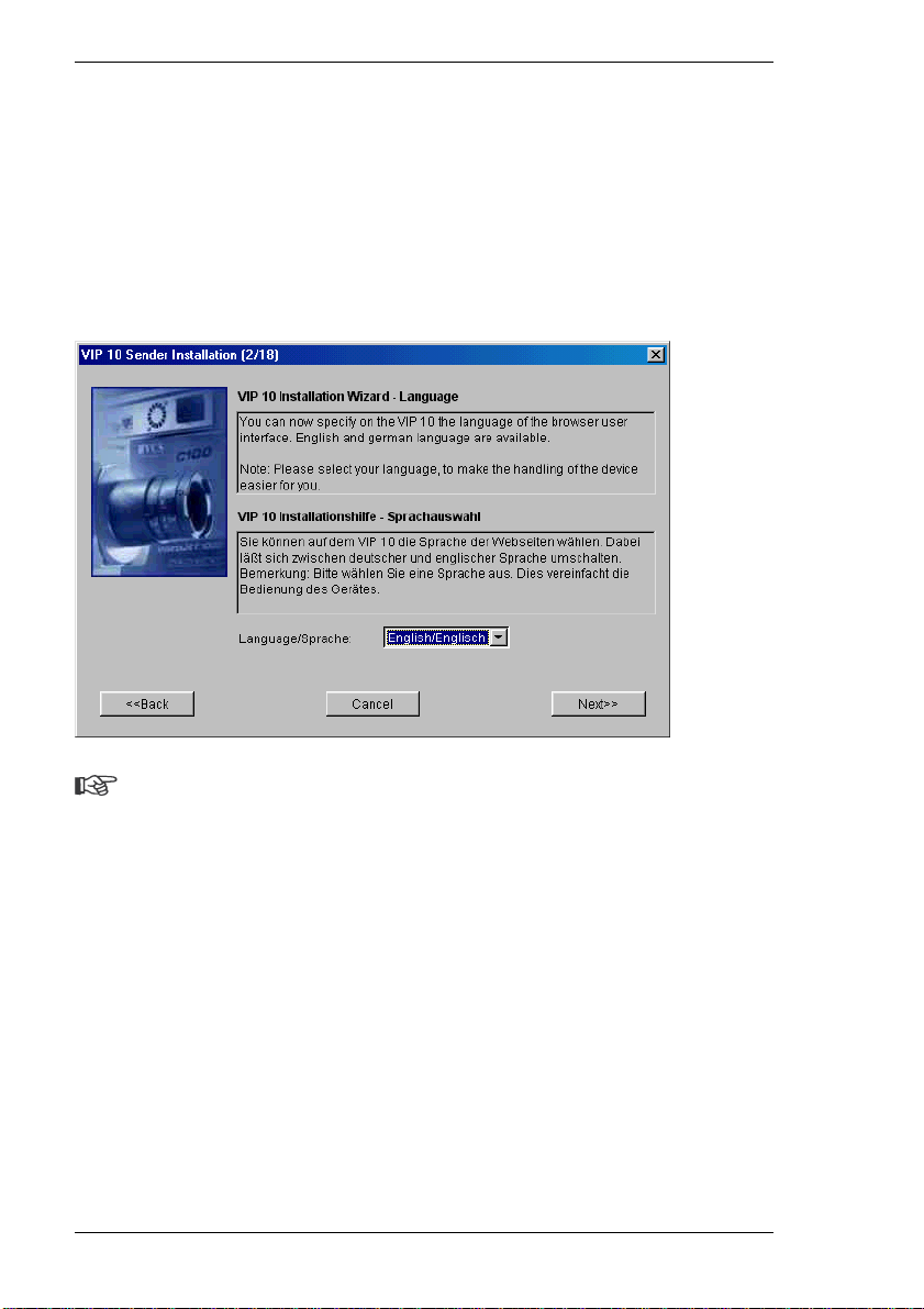
The screens for the Installation Wizard will be shown in sequence, allowing you
to work quickly and easily. The upper part of the window always contains
information about the settings options. The current settings are shown in the
lower part of the window. You can change settings by entering the desired value
in a text field or choosing it from a list. The navigation buttons for the Installation
Wizard are at the bottom of the window. You can switch between pages of the
Wizard at any time.
Note
Your screen display may differ slightly from the illustration, depending on
whether you are working with a transmitter or a receiver and a VIP 10 or a
VIP 1000. However, the configuration procedure with the Installation
Wizard is the same for all units.
– First read the information provided.
– Make the desired settings.
– Click Next>> to proceed to the next screen.
or
– Click <<Back to return to the previous screen.
or
– Click Cancel to end the wizard without changing th e settings.
30 VIP 10 / VIP 1000
Page 31

Chapter 5 Configuration using a Web Browser
Finishing the configuration
After you have specified all the settings you want, they must be transmitted to the
VIP unit and saved. Click Finish in the last screen of the Installation Wizard to
complete this process.
Warning!
All settings changes will become effective only after you have ended the
configuration by clicking Finish in the last screen.
– Go to the last screen of the Installation Wizard if necessary.
– Click Finish to finalize the configuration. All settings will be transmitted to the
VIP and become effective forthwith.
VIP 10 / VIP 1000 31
Page 32
Configuration using a Web Browser Chapter 5
Configuration in Expert Mode
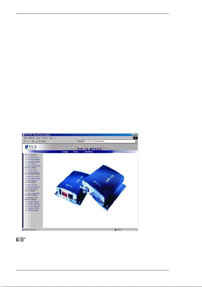
Expert Mode allows all parameters of the VIP to be configured. You can view the
current settings by opening one of the configuration pages. The settings can be
changed by entering new values or by selecting a predefined value in a list field.
The basic use of the configuration pages is described be low. Separate
descriptions of the individual configuration pages and customizable parameters
for transmitters and receivers can be found in Chapter 6 and Chapter 7 of this
user guide.
Navigation
You can switch to Expert Mode from the configuration pages.
– Click the Expert Mode link. The initial page will be opened.
– Click one of the links on the left of the window. Other subordinate links will be
shown.
– Click one of the links. The corresponding page will be opened.
Note
Your screen display may differ from the illustration, depending on whether
you are working with a transmitter or a receiver and a VIP 10 or a VIP 1000.
However, navigation on the configuration pages is the same for all units.
32 VIP 10 / VIP 1000
Page 33

Chapter 5 Configuration using a Web Browser
Making changes
Each configuration page shows the current settings. You can change the settings
by entering new values or by selecting from predefined lists. After each change,
click Set to save the change.
Warning!
Save each change with the associated Set button. When Set is clicked,
only the changes in the relevant (blue-bordered) field are saved. Changes
in any other fields are ignored.
VIP 10 / VIP 1000 33
Page 34

34 VIP 10 / VIP 1000
Page 35
Configuring the Transmitter 6
Basics
The VIP offers various configuration options. Configuration in Expert Mode with
a Web browser is described below. Basic information about configuration with a
Web browser and other configuration options are described in Chapter 5 of this
user guide.
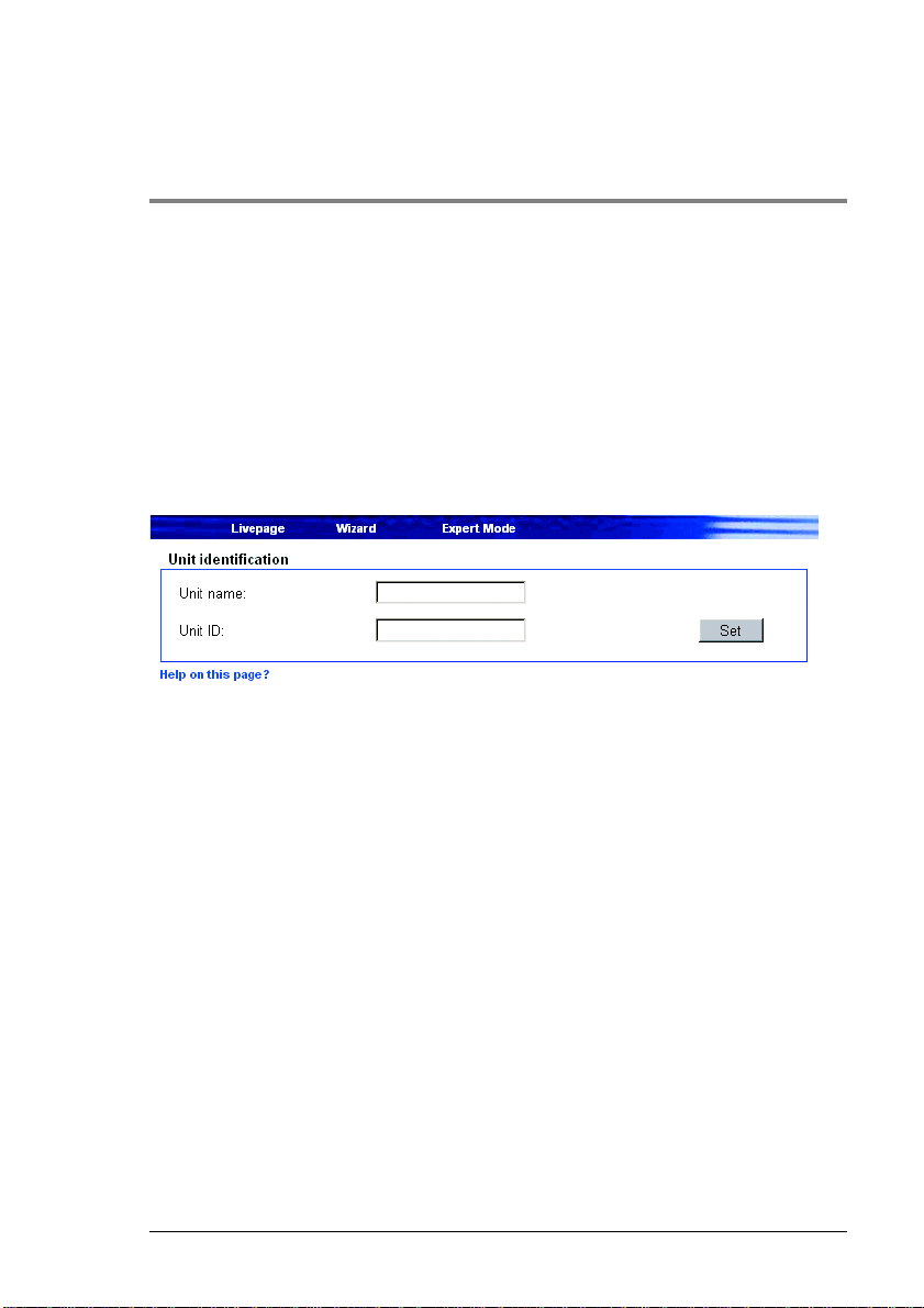
Unit identification
The unit can be assigned a name and an ID to facilitate identification. Both make
the task of managing video surveillance systems with VIDOS from VCS or other
tools much simpler.
Unit name:
Enter a name for the unit here.
Unit ID:
Each VIP should be assigned a unique identifier that can be entered here as an
additional means of identification.
VIP 10 / VIP 1000 35
Page 36
Configuring the Transmitter Chapter 6
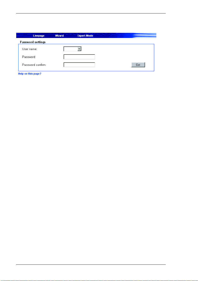
Password settings
A VIP unit is generally protected by a password to prevent unauthorized access.
User name:
The transmitter operates with three user names: Service, User and Live.
Once logged in under the user name Service, you can use all the functions
offered by the VIP and change all settings.
When logged in under User, you can operate the device and other devices, such
as a camera, but no changes can be made to the configuration.
The user Live can only view the live video image and switch between the various
live image feeds.
Password:
You can define and change a unique password for each user name if you are
logged on under Service or if the unit is not protected by a password. You can
change only one password at a time. In order to change the password for another
authorization level, you must reload this configuration page.
Password confirmation:
Re-enter the new password to prevent typing mistakes.
36 VIP 10 / VIP 1000
Page 37
Chapter 6 Configuring the Transmitter
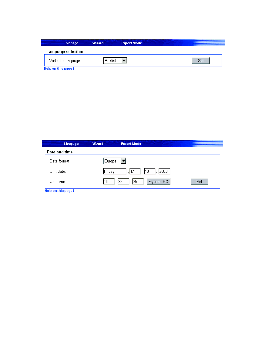
Language selection
If more convenient, a different operating interface language can be chosen.
Website language:
Select the language from the dropdown field.
Date and time
If a number of VIP units are part of a system, it is important that the internal clocks
of these separate units be synchronized. Only if all units operate with the same
time it is possible, for example, to correctly identify and evaluate recordings that
have been made simultaneously.
Date format:
Choose the desired date format here
(Europe: DD.MM.YYYY; USA: MM.DD.YYYY; Japan: YYYY/MM/DD).
Unit date:
Enter the current date here. Since the system time is controlled by the internal
clock, it is not necessary to enter the day of week. This is added automatically.
VIP 10 / VIP 1000 37
Page 38
Configuring the Transmitter Chapter 6
Unit time:
Enter the current time here or click the Synchr. PC button to copy the system
time of your computer to the VIP.
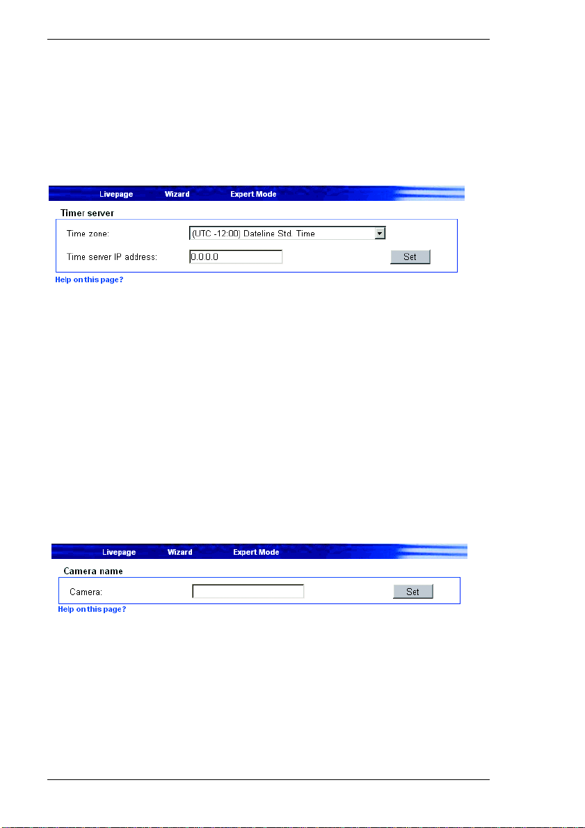
Timer server
The VIP can receive a time signal from a time server (NTP server) and use it to
set its internal clock. The device calls up the time signal automatically every two
hours.
Time zone:
Select the time zone that applies to your system.
Time server IP address:
Enter the IP address of the chosen NTP server here.
Camera name
The camera name simplifies identification of the remote camera location, for
example in the event of an alarm call. It will be shown in the video image if this
facility has been configured (see page 39). Moreover, the camera name is used
by VIDOS, VCS software for managing video surveillance systems, and makes it
easier to identify the camera.
38 VIP 10 / VIP 1000
Page 39
Chapter 6 Configuring the Transmitter
Camera:
Enter a unique, unambiguous name for the camera in this field.
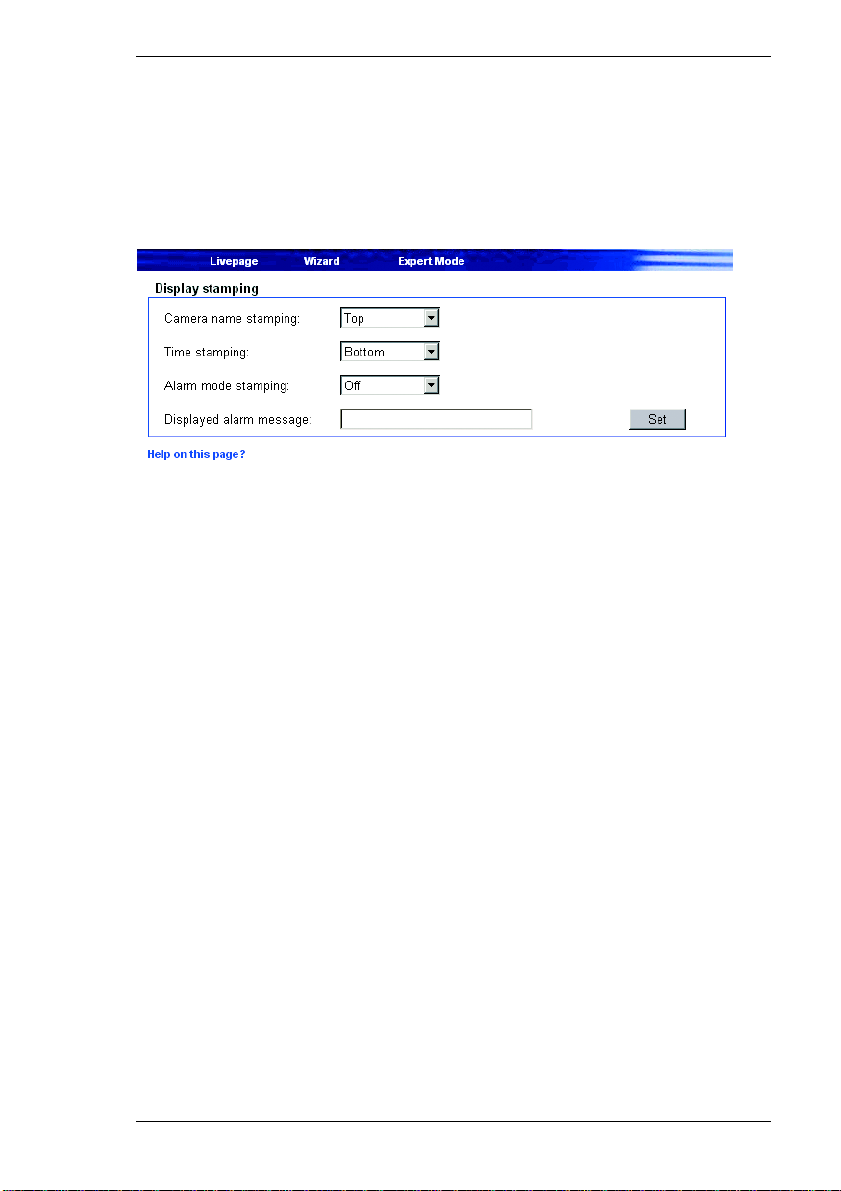
Display stamping
Various overlays or stamps in the video image provide important supplemental
information. These overlays can be enabled individually and arranged on the
image in a clear manner.
Camera name stamping:
This field sets the position of the camera name overlay. It can be shown at the
Top or the Bottom, or it can be set to Off if no overlay for this information is to
be shown.
Time stamping:
This field sets the position of the time and date overlay. It can be shown at the
Top or the Bottom, or it can be set to Off if no overlay for this information is to
be shown.
Alarm mode stamping: Choose On if a text message should be overlaid in the event of an alarm.
Displayed alarm message:
Enter the message to be displayed for an alarm. The field can contain up to 31
characters.
VIP 10 / VIP 1000 39
Page 40
Configuring the Transmitter Chapter 6
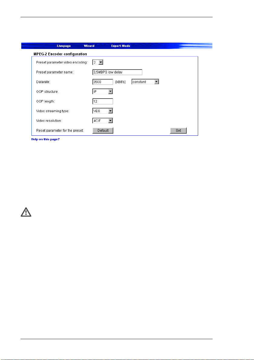
MPEG-2 Encoder configuration (VIP 1000 only)
The data transmission parameters can be configured to suit the local operating
environment (network architecture, bandwidth, data structures, etc.). Eight
preconfigured profiles are provided in MPEG-2 mode, each reflecting different
priorities and environments.
Individual settings in a profile can be changed, and the modified profile can be
saved under a new name.
Warning!
The profiles are rather complex. They include a number of parameters that
interact with one another. Therefore it is generally best to use the profiles
as provided. The profiles should only be changed once you have
familiarized yourself with all the configuration options.
Preset parameter video encoding / Preset parameter name:
Select a parameter value for the encoder from the dropdown field. The name
(description) of the value will be shown automatically in the field Preset
parameter name. The following values can be selected:
] 1 corresponds to 2MBPS low delay
2 MBit/s transmission rate with low image refresh delay
] 2 corresponds to 3.5MBPS low delay
3.5 MBit/s transmission rate with low image refresh delay
40 VIP 10 / VIP 1000
Page 41

Chapter 6 Configuring the Transmitter
] 3 corresponds to 5MBPS low delay
5 MBit/s transmission rate with low image refresh delay
] 4 corresponds to 2MBPS high quality
2 MBit/s transmission rate with high image quality
] 5 corresponds to 3.5MBPS high quality
3.5 MBit/s transmission rate with high image quality
] 6 corresponds to 5MBPS high quality
5 MBit/s transmission rate with high image quality
] 7 corresponds to 2MBPS with audio
2 MBit/s transmission rate with additional audio transmission
] 8 corresponds to 3.5MBPS with audio
3.5 MBit/s transmission rate with additional audio transmission
Data rate:
The data rate for the speed of transmission over the network is shown for each
parameter value. You can change the data rate and decide whether you prefer a
constant data rate or consistent image quality.
Selecting constant means that the data will always be transmitted at the set rate,
but the image quality may vary. Selecting variable means that the image quality
will be consistent, but the data rate can vary from the set value.
GOP structure: In MPEG-2 encoding, image sequences are divided into groups (GOP – Group
of Pictures). Each GOP can contain three different frame types. I-frames contain
the complete information for an image and thus require the most coding data. Pframes code only the difference between the current image and the previous one.
These require considerably less data. Lastly, B-frames encode only the
difference between the current image and the previous and next images. The
require the least data. However, B-frames have a large delay, because image
information from subsequent images is required for encoding. Each GOP always
begins with an I-frame.
Note
B-Frames have a large delay and are not suitable for some applications,
such as manually controlling a dome camera. Keep this in mind when
choosing a GOP structure and length.
VIP 10 / VIP 1000 41
Page 42

Configuring the Transmitter Chapter 6
Select the structure for the GOP. You can choose between:
] I
I-frames only
] IP
an I-frame followed by several P-frames
] IPB
an I-frame followed by several substructure sequences, each consisting of a
P-frame and a B-frame
] IPBB
an I-Frame followed by several substructure sequences, each consisting of a
P-frame and two B-frames
GOP length:
Enter the image interval between I-frames here. The value will depend on the
GOP structure selected. It must always be a multiple of the P- frames and Bframes in the GOP structure.
In the context of the GOP structure IPB, a length of 4 means that an I-frame is
followed by a total of four other frames, which are alternately P- and B-frames.
The resultant image structure is: IPBPBIPBPBIPBPB …
The GOP structure IP can have any GOP length. The IPB structure must have a
GOP length that is a multiple of two. The IPBB structure has length that is a
multiple of three. The GOP structure I requires no GOP length.
Video stream type:
You can choose between the types VES (Video Elementary Stream) and PRG
(Program Stream). Select PRG if audio is to be transmitted together with the
video images. Audio signals require an additional bandwidth of about 256 kBit/s.
Note
Choosing VES results in no encoding of audio data.
42 VIP 10 / VIP 1000
Page 43
Chapter 6 Configuring the Transmitter
Video resolution:
Select the desired resolution for the MPEG-2 video image. The following options
are available:
] CIF 352 × 288 pixels
] 4CIF 704 × 576 pixels
Reset this parameter preset: Click the Default button to reset the profile to its factory presets.
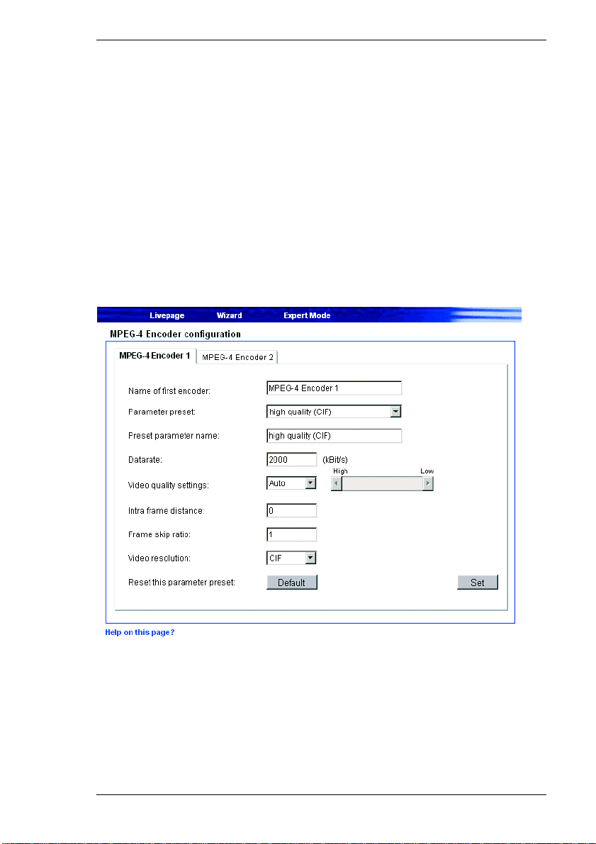
MPEG-4 Encoder configuration
The VIP transmitter has two MPEG encoders that can be configured separately.
The benefit of this so-called "dual encoding" is that you can transmit and record
simultaneously with different compression settings. The parameters for each can
be configured to suit the environment used (network architecture, bandwidth,
data structures, etc.).
VIP 10 / VIP 1000 43
Page 44

Configuring the Transmitter Chapter 6
There are several pre-programmed profiles available for both MPEG encoders.
These are optimized for different application scenarios. Individual settings in a
profile can be changed, and the modified profile can be saved under a new name.
Warning!
The profiles are rather complex. They include a number of parameters that
interact with one another. Therefore it is generally best to use the profiles
as provided. The profiles should only be changed after you have
familiarized yourself with all the configuration options.
You can switch between the parameters of the two MPEG-4 encoders by clicking
the associated tabs. The choice of Video Livepage encoder is set on the
Livepage configuration page (see page 62).
Note
The parameters as a group constitute a profile and are dependent on one
another. If you enter a setting outside the allowed range for the parameter,
the nearest valid value will be substituted when the settings are saved.
Name of first (second) encoder:
Enter a unique name for each encoder. The name of the encoder will also be
shown on the Livepage configuration page.
Parameter preset:
Eight pre-programmed profiles are available for each of the two MPEG-4
encoders. These are optimized for different transmission modes:
] high quality (CIF)
for connections with high bandwidth, resolution 352 × 288 pixels
] high res. (2CIF)
for connections with high bandwidth, resolution 704 × 288 pixels
] low res. (QCIF)
for connections with low bandwidth, resolution 176 × 144 pixels
] DSL
for DSL connections with 500 kbit/s
] ISDN (2B)
for ISDN connections via two B channels
44 VIP 10 / VIP 1000
Page 45

Chapter 6 Configuring the Transmitter
] ISDN (1B)
for ISDN connections via one B channel
] MODEM
for analog modem connections at 20 kBit/s
] GSM
for 9600 baud GSM connections
Preset parameter name:
Enter a name for the current profile. The name will be displayed automatically in
the field Parameter preset.
Datarate:
Enter a value for the transmission rate of data over the network.
Video quality settings:
Here you can adjust video quality as a function of the level of movement within
the frame. The Auto option automatically adjusts to the optimum relationship
between movement and image definition (focus). Manual allows you to set a
value between 1 and 31 on a slide bar. The value 1 gives the highest quality with
the lowest frame refresh rate. The value 31 results in a high refresh rate and low
image quality.
Intra frame distance:
This parameter determines the number of frames between two I-frames
Frame skip ratio:
This setting determines the frame encoding interval. The value 1 means each
image is encoded. The value 2 means that only every other image is encoded,
etc. The lower the available transmission bandwidth, the higher this value should
be set in order to maintain high-quality images despite the bandwidth.
Video resolution:
Select the desired resolution for the MPEG-4 video image. The following options
are available:
VIP 10 / VIP 1000 45
Page 46
Configuring the Transmitter Chapter 6
] QCIF 176 × 144 pixels
] CIF 352 × 288 pixels
] 2CIF 704 × 288 pixels
Reset this parameter preset: Click the Default button to reset the profile to its factory presets.
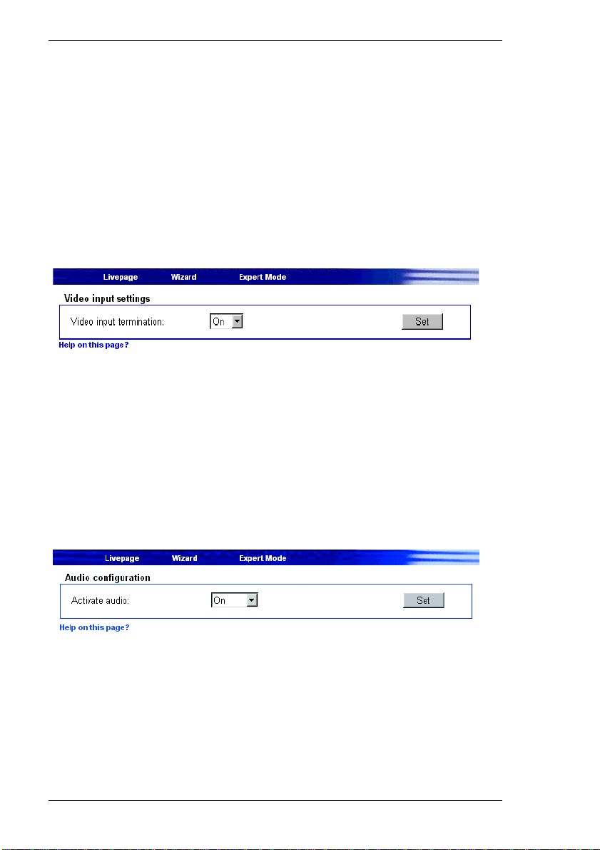
Video input settings
The 75 Ohm termination of the VIP can be set here. If the video signal is to be
looped through, the termination must be set off. The default setting for the video
input termination is On.
Video input termination: To loop the video signal through choose Off.
Audio configuration
In addition to video data, the unit can also transmit audio signals. The
transmission of audio takes place at the same time as that of the video data and
thus increases the size of the data stream. If you use the MPEG-4 format for
video data, audio transmission can be activated separately here. In this case, the
audio data stream requires an additional bandwidth of about 80 kBit/s.
46 VIP 10 / VIP 1000
Page 47
Chapter 6 Configuring the Transmitter
Note
If you work with the MPEG-2 video format, you must choose PRG as the
video stream in order to transmit audio at the same time as video data (see
page 42).
Warning!
Audio data is only saved with central recording, using VIDOS-NVR for
example.
Activate audio: To transmit an audio stream together with the MPEG-4 video choose On.
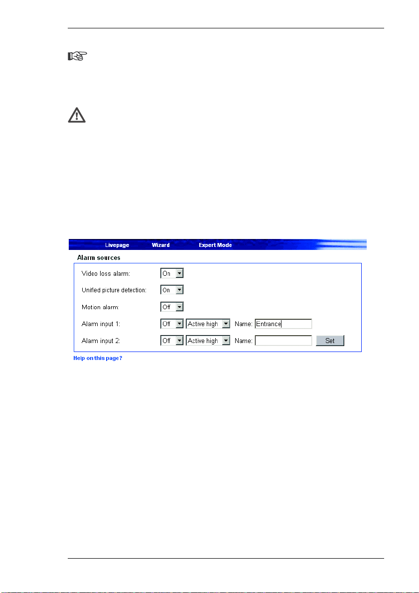
Alarm sources
You can configure the possible alarm triggers for the VIP (e.g. the alarm inputs).
Video loss alarm:
Select On if the unit is to activate an alarm whenever the video signal is
interrupted.
Unified picture detection:
The VIP can trigger an alarm if the camera image shows too little contrast,
possibly indicating that the lens has been sprayed with paint or covered in some
way. Select On to enable this function.
VIP 10 / VIP 1000 47
Page 48
Configuring the Transmitter Chapter 6
Motion alarm:
Select On if the unit is to respond to a motion alarm.
Motion detection is configured on a separate page (see page 50).
Alarm input 1:
Select On if the alarm is to be activated by external alarm sensor 1.
Furthermore, you can choose whether the alarm is to be activated by an Active
high or Active low voltage level.
Enter a designation for the alarm input in the Name field. This name will be shown
on the Video Livepage next to the associated alarm icon.
Alarm input 2:
Select On if the alarm is to be activated by external alarm sensor 2.
Furthermore, you can choose whether the alarm is to be activated by an Active
high or Active low voltage level.
Enter a designation for the alarm input in the Name field. This name will be shown
on the Video Livepage next to the associated alarm icon.
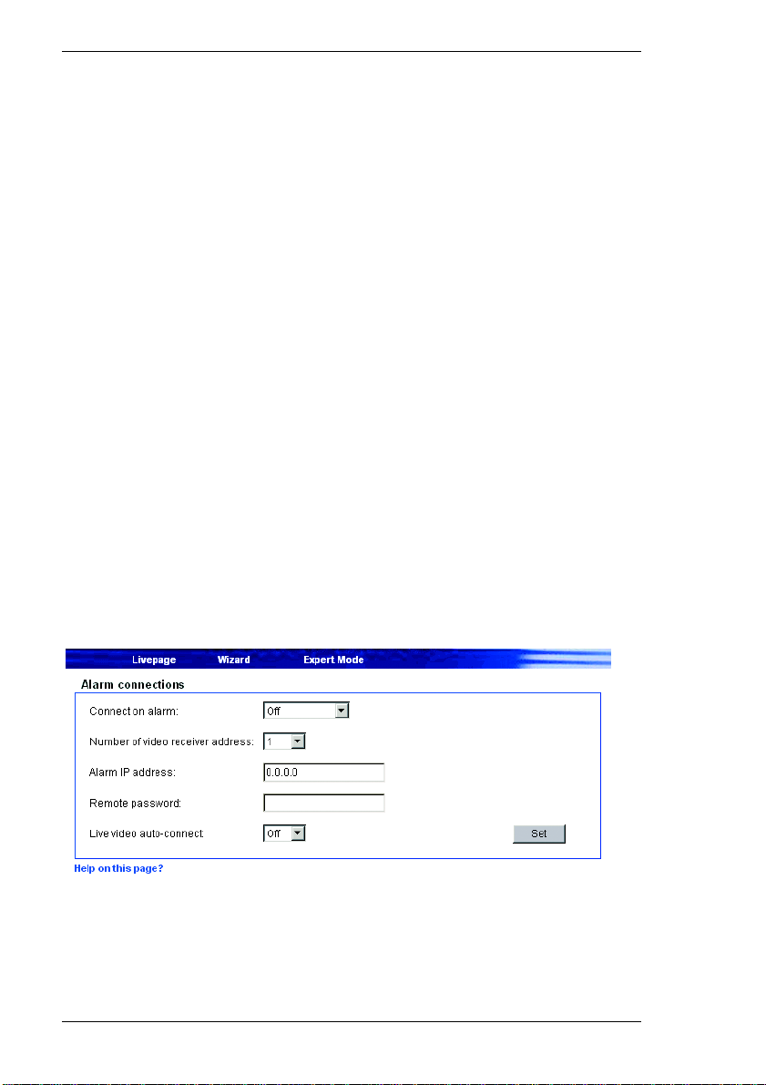
Alarm connections
You can select a number of options determining how the VIP responds to an
alarm. For example, the VIP can automatically connect to a predefined IP
address (VIP receiver or a PC with receiver software).
48 VIP 10 / VIP 1000
Page 49

Chapter 6 Configuring the Transmitter
Connect on alarm:
Select On, to establish a connection automatically to a specified IP address in the
event of an alarm.
With the setting Follows input 1, the VIP establishes an automatic connection to
a remote location as long as an alarm signal is present at the alarm input 1.
Connection type in the event of an alarm (VIP 1000 only):
Here you can select the transmission standard for the alarm connection to the
specified IP address dependent on the environment used (network
configuration). In doing so, consider the settings used for MPEG-2 and MPEG-4
(refer to page 40).
Number of video receiver addresses:
The VIP can store up to 10 IP addresses to contact in response to an alarm. In
case of an alarm, if the first IP address cannot be reached, the others will be tried
in sequence until a connection can be established. Select the contact priority of
the IP address here.
Alarm IP address:
Enter the IP address with which a connection is to be established in the event of
an alarm.
Remote password:
Enter the password for the remote device (if it has one) that is to be contacted in
response to an alarm.
Live video auto-connect:
Select On here if an active connection should be established after each reboot,
for example following a connection failure or power failure.
VIP 10 / VIP 1000 49
Page 50
Configuring the Transmitter Chapter 6
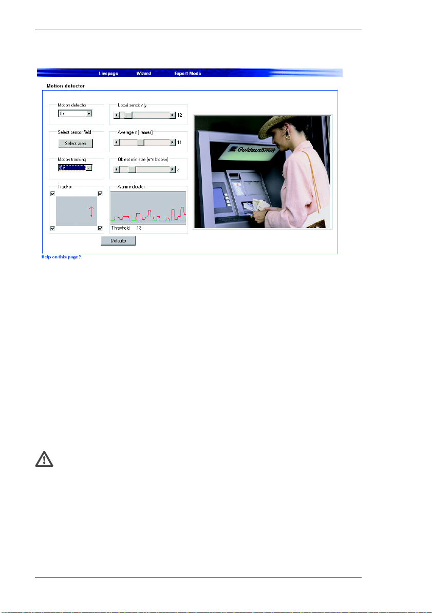
Motion detector
The VIP contains an integrated video sensor that can register changes in the
video signal based on image processing. These changes are triggered primarily
by any movement that is detected in the camera's field of view.
The sensitivity of the video sensor can be adjusted, so that an alarm is generated
only if a given threshold is exceeded.
In order for the sensor to function, the following conditions must be satisfied:
] The motion detector must be enabled.
] At least one cell must be activated.
] Individual parameters must be configured correctly to suit the operating
environment and the responses desired.
] The sensitivity must be set to a value greater than zero.
Warning!
Reflections of light (off glass surfaces, etc.), switching lights on or off or
changes in the light level caused by clouds passing across the sun can
spuriously trigger the video sensor and generate false alarms. Perform
sufficient tests during the day and night in order to ensure correct operation
of the video sensor. When the system is used for surveillance of indoor
areas, ensure constant lighting during the day and at night. Uniform
50 VIP 10 / VIP 1000
Page 51

Chapter 6 Configuring the Transmitter
surfaces without contrast can trigger false alarms even when light levels are
constant.
Note
Clicking the Defaults button will reset the video sensor to its factory
configuration.
Motion detector Select On to activate the video sensor.
Select sensor field
You can select the areas of the image to be monitored by the video sensor. The
video frame is subdivided into 396 square cells. Each of these cells can be
activated or deactivated individually. If it is necessary to exclude particular
regions of the camera field of view from the monitoring process due to continuous
movement (a tree moving in the wind, etc.), the relevant cells can be deactivated.
– Click Select area to configure the sensor cells. A new window will open.
– If necessary, click Clear all first to clear the current selection (cells marked
red).
– Left-click the cells to be activated. Activated cells are marked red.
– Click Select all if you want to select the entire video frame for monitoring.
– Right-click any cells you wish to deactivate. "Inactive" cells are marked white.
– Click Set to save the configuration.
– Click the close button (X ) in the window title bar to close the window without
saving the changes.
Local sensitivity
The basic sensitivity of the video sensor can be adjusted for the environmental
conditions to which the camera is subject.
The sensor reacts to variations in the brightness of the video image. The darker
the observation area, the greater the value that must be selected here.
– Adjust the sensitivity by dragging the scroll thumb to the desired setting.
VIP 10 / VIP 1000 51
Page 52

Configuring the Transmitter Chapter 6
Average [n frames]
It is possible to define the number of frames in which a movement is detected in
order to generate an alarm. This can help prevent false alarms from events such
as a bird flying through the surveillance area.
– Select the desired value by dragging the scroll thumb to the desired position.
Object min size [n*n blocks]
You can specify the number of sensor cells that a moving object must cover to
generate an alarm. This can prevent objects that are too small from triggering an
alarm.
A minimum value of 2 (2 × 2 sensor fields) is recommended.
– Select the desired value by dragging the scroll thumb to the desired position.
Alarm indicator
To prevent false alarms, a threshold can be applied to the motion signal. This
allows effects such as the background noise from the camera itself to be filtered
out.
The blue line in the illustration represents the alarm threshold. Any value above
this level will trigger an alarm. The parts of the motion signal line which will cause
an alarm are shown in red. The alarm threshold can be set higher or lower to suit
your needs.
– Observe the amplitude of the displayed movement signal over a longer period
of time under all the lighting conditions that may be encountered.
– Move the pointer over the blue line.
– Press the left mouse button in and drag the line to the desired level.
Motion tracking
In some situations you may want an alarm triggered only if movement takes place
in a particular direction. In such cases, enable motion detection and select the
direction of movement required to trigger an alarm.
– Select On to enable the motion tracking feature of the video sensor.
52 VIP 10 / VIP 1000
Page 53
Chapter 6 Configuring the Transmitter
Tracker
The Tracker field shows an arrow indicating the current motion vector in the
video image. The checkboxes at the corners of the field are used to select the
directions to monitor. For example, if all movements toward the left and up are to
trigger an alarm, mark the top left corner. If all movement to the left is to trigger
an alarm, mark the upper left and the lower left checkboxes.
– Observe the movement in the video image indicated by the arrow over a longer
period of time at all the relevant light levels.
– Mark the checkboxes to activate the corresponding directional components for
monitoring.
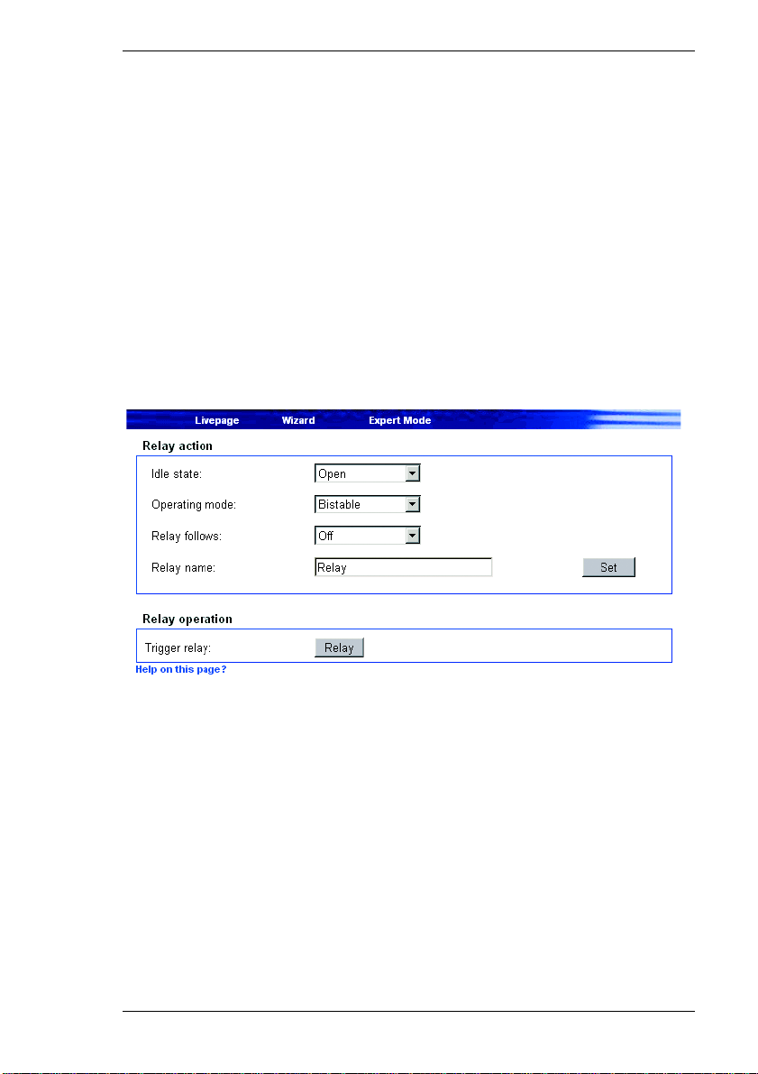
Relay action / Relay operation
You can configure the switching behavior of the relay output. Relay action can be
specified either as open switch (normally closed contact) or closed switch
(normally open contact).
It is also possible to specify whether the output signal should be bistable or
monostable. With bistable operation, the relay remains in the activated state.
With monostable operation, the delay time can be selected after which the relay
reverts to its idle state.
You can choose various events that activate the output automatically. Thus, for
example, it is possible to switch on a spotlight in response to a motion alarm and
switch it off again when the alarm situation is no longer active.
VIP 10 / VIP 1000 53
Page 54

Configuring the Transmitter Chapter 6
Idle state:
Select Open if the relay is to operate as a normally open contact or Closed if it
is to operate as a normally closed contact.
Operating mode:
Select an operating mode for the relay.
If, for example, a light switched on by an alarm is to remain lit when the alarm has
ended, select Bistable. If an audible signal activated by an alarm is to sound for
a period of ten seconds for example, select 10 s.
Relay follows:
Select a particular event to trigger the relay. The following events can activate the
relay:
] Off
No relay triggering by events
] Connection
Triggering whenever a connection is established
] Video alarm
Triggering caused by loss of the video signal
] Motion alarm
Triggering by the motion alarm
] Local input 1
Triggering by the alarm input 1
] Remote input 1
Triggering by a relay contact at the target location (only when a connection is
established)
] Unified picture
Triggering caused by a lack of contrast in the picture
Relay name:
A name can be assigned to the relay in this field. The name will be shown on the
button under Trigger relay. The Livepage can also be configured to display the
name next to the relay icon.
54 VIP 10 / VIP 1000
Page 55
Chapter 6 Configuring the Transmitter
Trigger relay:
Click the button to switch the relay manually (for example for test purposes or to
operate a door opener).
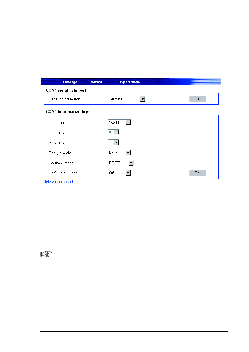
COM1 serial data port / COM1 interface settings
The serial interface port RS232/485 can be configured to suit your specific
requirements.
Serial port function:
Select a controllable device from the list. If you want to use the serial interface to
transmit transparent data, select Transparent. To operate the VIP with a
terminal, choose Terminal.
Note
After selecting a unit, the remaining parameters in the window are set
automatically and should not be altered.
Baud rate:
Select the value for the data communication rate in Bit/s.
VIP 10 / VIP 1000 55
Page 56
Configuring the Transmitter Chapter 6
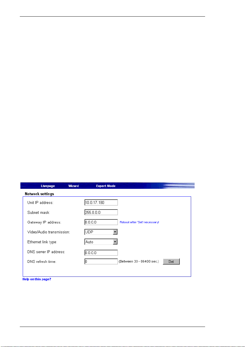
Data bits:
The number of data bits per character cannot be changed.
Stop bits:
Select the number of stop bits per character.
Parity check:
Select the type of parity check.
Interface mode:
Select the desired protocol for the serial interface.
Half-duplex mode:
Choose the setting appropriate for your application.
Network settings
The settings on this page are used to integrate the unit into an existing network.
56 VIP 10 / VIP 1000
Page 57

Chapter 6 Configuring the Transmitter
Warning!
Although the modified network settings are copied to the VIP when the Set
button is clicked, they become effective only after the unit has been
restarted. To do this, enter the old IP address with /reset appended to it
in the address field of the Web browser. The unit will be accessible only at
its new IP address after this action.
Unit IP address:
Enter the desired IP address for the VIP in this field. The IP address must be
recognized by the network.
Subnet mask:
Enter the corresponding subnet mask here if the unit is to communicate via a
subnet.
Gateway IP address:
Enter the corresponding IP address here if the unit is to establish a connection
outside the local network independently. Otherwise, this field can remain empty
(0.0.0.0).
Video/Audio transmission:
If the device is used in front of a firewall, TCP (Port 80) should be selected as the
transmission protocol. For use in a local network, choose UDP.
Warning!
Multicast operation is possible only with the UDP protocol. The TCP
protocol does not support multicast connections.
Ethernet link type:
Adjust here the ethernet link to the network. In most applications Auto is the
correct choice. For some routers and switches it can be necessary to set the
Ethernet link to a fixed value. In that case select the appropriate value:
] 10 MBit/s HD = 10 MBit/s half-duplex
] 10 MBit/s FD = 10 MBit/s full-duplex
VIP 10 / VIP 1000 57
Page 58

Configuring the Transmitter Chapter 6
] 100 MBit/s HD = 100 MBit/s half-duplex
] 100 MBit/s FD = 100 MBit/s full-duplex
DNS Server IP address:
Working with a device over the Internet dynamic IP addresses are assigned for
efficient use of the IP address pool, i.e. the device gets a new (changing) IP
address each time a connection is set up.
Connecting is easier when the device is listed on a DNS server. The device logs
in regularly leaving the device name, device IP address and the current Internet
IP address. To connect to a device over the Internet you just insert the device
name together with the URL of the DNS server which then returns the valid
Internet IP address for automatic connection set up.
The default setting for the DNS server IP address is the IP address of the VCS
DNS server videotec.info. The VIP contacts the server automatically when a
refresh time is specified in the next parameter. If e.g. the name of the VIP is
myVIP just type myVIP.videotec.info as URL to set up a connection.
Note
Assign a unique name to the VIP if you want to use this feature.
DNS refresh time:
Enter here the time interval for the VIP to contact the DNS server. You can enter
a value from 30 to 86400 sec (24 h). Leave this field empty when you don't want
to use the DNS function.
58 VIP 10 / VIP 1000
Page 59
Chapter 6 Configuring the Transmitter
Multicast settings
In addition to a "one on one" connection (unicast) between a transmitter and a
receiver, the VIP also supports multiple connections. With multicasting, several
receivers receive the video signal from the transmitter at the same time. There
are two methods for multiple connection: multi-unicast opera tion and multicast
operation.
In multi-unicast mode, the unit's data stream is duplicated and passed on to
multiple receivers.
Note
This places a heavy demand on the units' CPU that can lead to reductions
in image quality.
In multicast mode, duplication of the data stream takes place on the network itself
After duplication, the data is also then passed to multiple receivers.
Note
The prerequisite for multicast operation is a network enabled for
multicasting with the IGMP group management protocol and data transfer
via UDP.
Even with multiple connections, a transparent data connection can be
established only to a single device, usually the first receiver connected. However,
after about five seconds of inactivity, the data connection is automatical ly
suspended and another receiver can exchange transparent data with the
transmitter.
The audio link is likewise established only with a single receiver. It is also
generally maintained by the first receiver connected until that connection is
closed.
VIP 10 / VIP 1000 59
Page 60

Configuring the Transmitter Chapter 6
The VIP supports multi-unicast operation fo r MPEG-4 for up to five simultaneously
connected receivers. With the settings Multicast streaming: MPEG-4 and
Multicast group IP address: 0.0.0.0 the VIP operates in multi-unicast mode.
With the settings Multicast streaming: MPEG-4 and a valid multicast group IP
address, the unit functions in multicast mode.
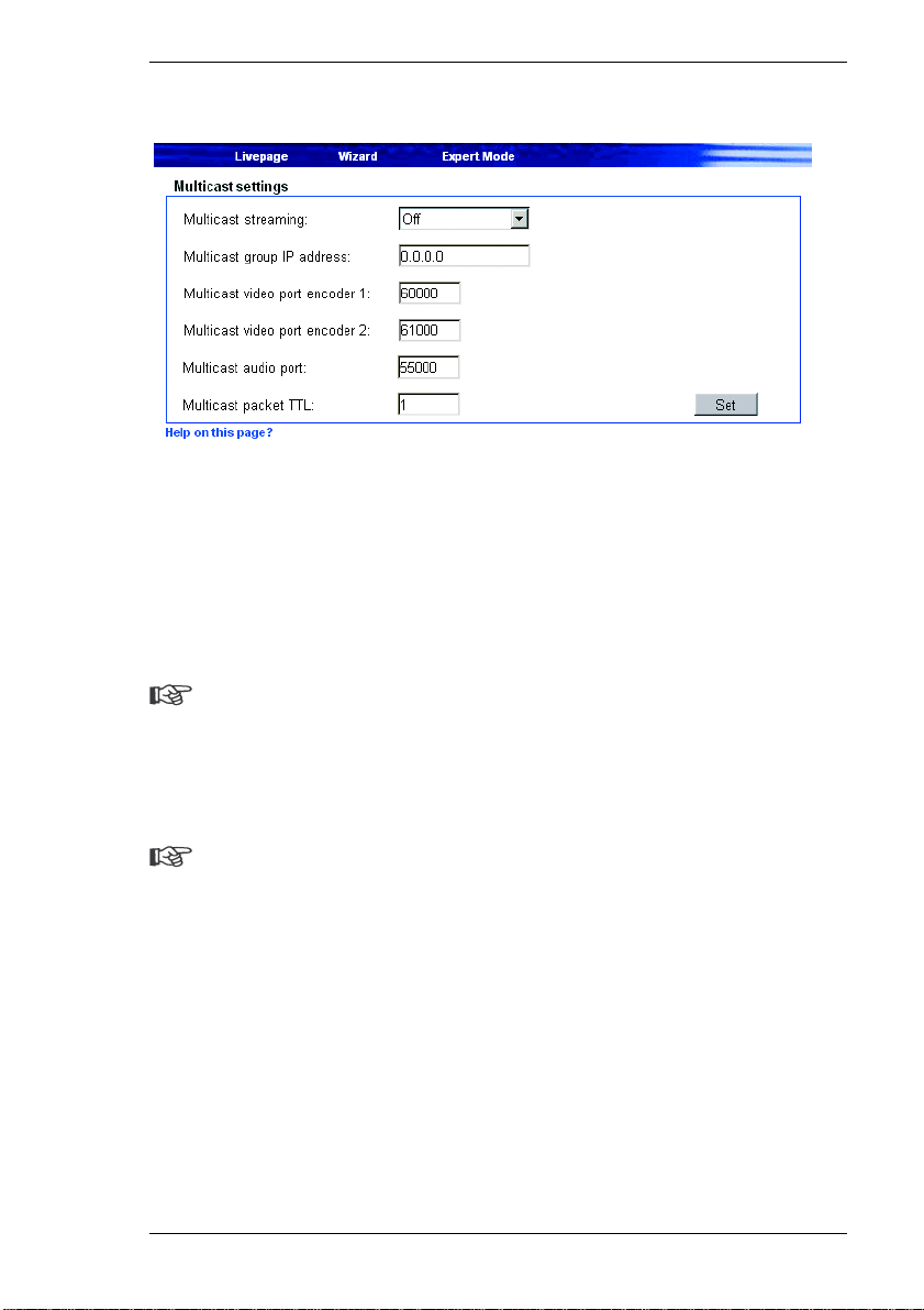
Multicast streaming:
Select an option to enable multicast operation. The options available depend on
the unit concerned. Off disables multicast operation.
Multicast group IP address:
A special IP address (class D address) must be configured for multicast operation
in a multicast-enabled network.
The network must support group IP addresses and the Internet Group
Management Protocol (IGMP). The address range is from 224.0.1.0 to
238.255.255.255.
Multicast video port encoder 1 (VIP 10 only):
Enter the port address for the video port of encoder 1.
Multicast video port encoder 2 (VIP 10 only):
Enter the port address for the video port of encoder 2.
Multicast MPEG-2 video port encoder (VIP 1000 only):
If there are simultaneous data streams in MPEG-2 and MPEG-4 formats, the data
for each must be assigned to different ports. Enter the port address for the
MPEG-2 data stream here.
Multicast video port encoder (VIP 1000 only):
If there are simultaneous data streams in MPEG-2 and MPEG-4 formats, the data
for each must be assigned to different ports. Enter the port address for the
MPEG-4 data stream here.
60 VIP 10 / VIP 1000
Page 61
Chapter 6 Configuring the Transmitter
Multicast MPEG-4 audio port:
With MPEG-4, video and audio data is transmitted via separate ports. To transmit
MPEG-4 with audio you must assign a dedicated audio port.
Enter the port address for the audio stream here.
Note
Audio data are only transmitted if the corresponding function on the Audio
configuration page is enabled (see page 47).
Multicast packet TTL:
This value determines the "life span" of multicast packets on the network. If
multicast is operated via a router, the value must be greater than 1 to ensure that
the packets are passed on.
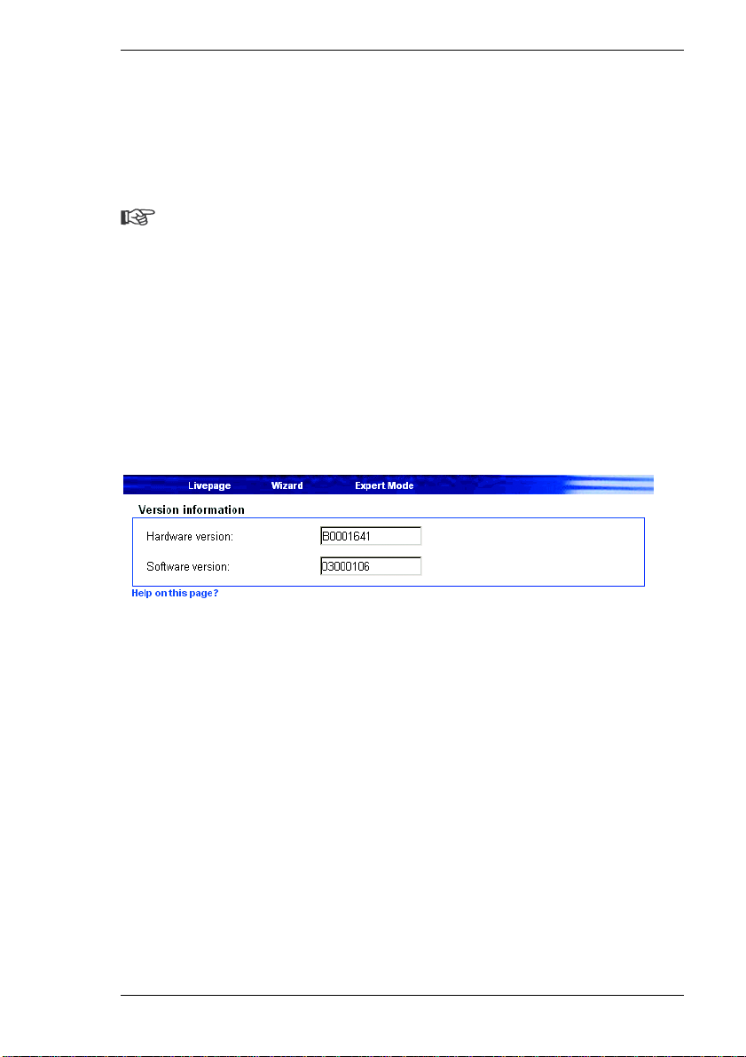
Version information
The hardware and software version numbers are for information only and cannot
be altered. Keep a record of these numbers in case technical assistance is
required.
Hardware version:
The hardware version number of the VIP is displayed.
Software version:
The software version number of the VIP is displayed.
VIP 10 / VIP 1000 61
Page 62
Configuring the Transmitter Chapter 6
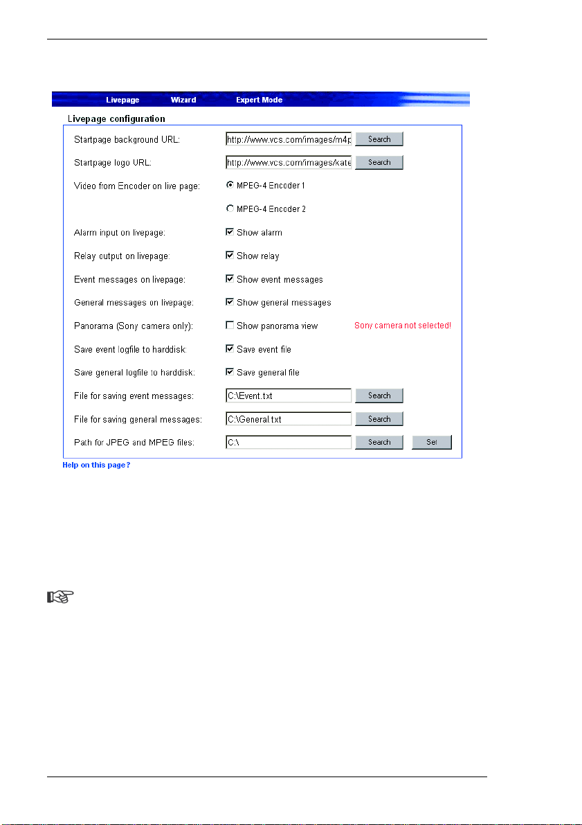
Livepage configuration
The appearance of the Livepage can be set up to suit your requirements. You
have the option of displaying various information and operating controls in
addition to the video image.
Moreover, individual background graphics can be used for the main window and
for the upper area of the window (banner).
Note
Either GIF or JPEG file formats can be used. The file paths must
correspond to the access mode (local paths such as C:\Images\Logo.gif for
local files and URLs such as http://www.vcs.com/images/logo.gif for files on
the Internet). Please note that access to network files requires that the
connection be maintained in order to continue displaying the image. The
image files are not stored on the VIP. To restore the original graphics, just
delete the entries in the fields Startpage background URL and Startpage
logo URL.
62 VIP 10 / VIP 1000
Page 63

Chapter 6 Configuring the Transmitter
– Mark the checkboxes for the information to be displayed on the Livepage. The
selected elements are marked.
– Check the display of the desired information on the Livepage.
Startpage background URL:
Enter the path to a suitable background grap hic. The image can be stored on a
local computer, a local network or an Internet address.
– If necessary, click Search to find a suitable image on the local network.
Startpage logo URL:
Enter here the path for a suitable image for the upper part of the window (banner).
The image can be stored on a local computer, a local network or an Internet
address.
– If necessary, click Search to find a suitable image on the local network.
Video from Encoder on live page (VIP 10 only):
Select an encoder for the video image on the Livepage.
Panorama (Sony camera only):
Selecting this option enables the display of a panoramic image. The panoramic
image is shown in the upper part of the browser window. It consists of five single
images that can be updated any time (see page 86).
Note
The panoramic image facility is only available with Sony EVI-D100 or EVID30/31 cameras.
Save event logfile to harddisk:
Select this option to save event data in a text file on the local computer.
These text files can be viewed , edi ted and printed with Microsoft Office software
(such as Microsoft Word or Excel).
VIP 10 / VIP 1000 63
Page 64
Configuring the Transmitter Chapter 6
Save general logfile to harddisk:
Select this option to save the general log entries in a text file on the local
computer.
These text files can be vie wed, edited and printed with Microsoft Office software
(such as Microsoft Word or Excel).
File for saving event messages:
Enter the path for the event message log file here.
– If necessary, click Search to find a suitable folder.
File for saving general messages:
Enter the full path for the general system messages log file.
– If necessary, click Search to find a suitable folder.
Path for JPEG and MPEG files:
Enter the full path to the storage location for individual images and MPEG
recordings to be saved from the Livepage.
– If necessary, click Search to find a suitable folder.
Software update
Software upload:
The VIP is designed so its functions and parameters can be updated with
firmware. To do this, you transmit the latest firmware update to the unit via the
64 VIP 10 / VIP 1000
Page 65

Chapter 6 Configuring the Transmitter
selected network. The firmware will be installed there automatically after the
connection is closed.
This allows a VIP unit to be serviced and updated remotely without intervention
by a technician to make on-site changes to the unit installation.
The latest firmware can be obtained from VCS Customer Service or downloaded
from the Internet at our Web site www.vcs.com.
Warning!
Before starting the firmware upload, be certain that you have selected the
correct upload file! Uploading the wrong files can result in the unit no longer
being addressable, requiring it to be replaced. Never interrupt the
installation of the firmware. Interruption will damage the Flash EPROM.
This can also render the unit inoperable and make replacement necessary.
– First, save the update file to the hard disk.
– Enter the full path for the update file in the field or click Durchsuchen... to
locate and select the file.
– Click Upload to begin transmission to the unit. Transmission progress can be
monitored from the status messages and the progress bar.
After the upload is completed successfully, the unit will restart automatically.
If the operating status LED flashes red and green alternately, the upload has
failed and must be done again. This requires that you work from a special page:
– Enter the IP address of the unit in the browser and append /main.htm (for
example 192.168.0.12/main.htm).
– Repeat the upload.
Configuration download:
You can save the unit's configuration data to a PC.
– Click Download. A dialog box will appear.
– Follow the instructions in the dialog box to save the current settings.
Configuration upload:
You can upload configuration data that you previously saved to a PC, to the unit.
VIP 10 / VIP 1000 65
Page 66

Configuring the Transmitter Chapter 6
– Enter the full path of the file to upload or click Durchsuchen... to select the
desired file.
– Make sure that the file to load is of the same type as the unit you want to
reconfigure.
– Click Upload to start transmitting the file to the unit.
This message will appear: Configuration upload finished. State:
Configuration upload ok (the system must be rebooted), and the
countdown for reconnection will be displayed.
– Restart the unit.
The next time the software update page is opened, the message Configuration
upload ok confirms the successful completion of the upload. If the message
Configuration upload failed is displayed, the file did not upload correctly.
Repeat the upload in this case, possibly with a different file.
Function test
The VIP offers a variety of configuration options. Therefore you should check that
it works properly after installation and configuration. Only in this way can you
ensure that the VIP will also function properly in an alarm situation.
Check for the following (among other things):
] the VIP can be contacted remotely,
] the VIP transmits all the required data,
] the VIP responds as configured to alarm events and
] that any peripheral devices respond properly to control signals.
66 VIP 10 / VIP 1000
Page 67
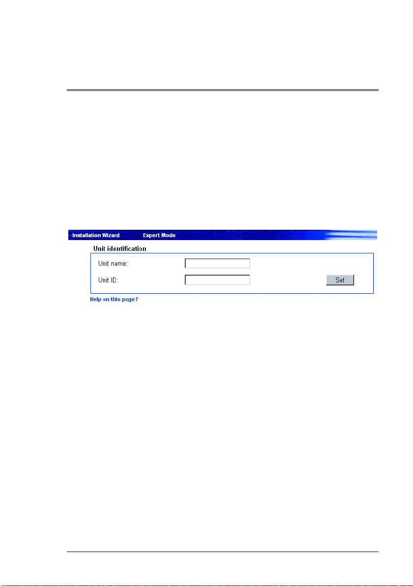
Configuring the Receiver 7
Basics
The VIP offers various configuration options. Configuration in Expert Mode with
a Web browser is described below. Basic information about configuration with a
Web browser and other configuration options are described in Chapter 5 of this
user guide.
Unit identification
The unit can be assigned a name and an ID to facilitate identification. Both make
the task of managing video surveillance systems with VIDOS von VCS or other
tools much simpler.
Unit name:
Enter a name for the unit here.
Unit ID:
Each VIP should be assigned a unique identifier that can be entered here as an
additional means of identification.
VIP 10 / VIP 1000 67
Page 68
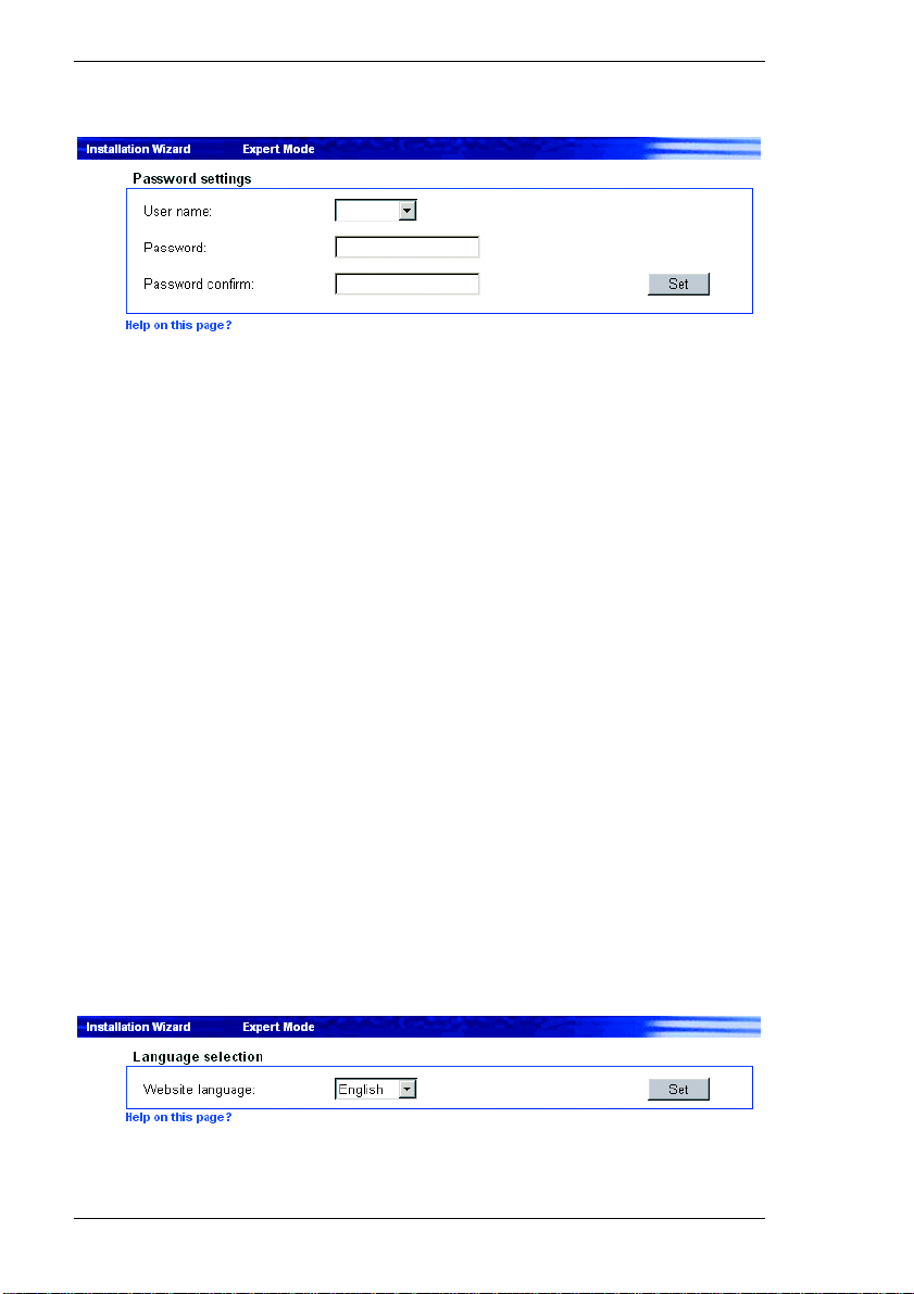
Configuring the Receiver Chapter 7
Unit password
A VIP unit is generally protected by a password to prevent unauthorized access.
User name:
The receiver operates with two user names: Service and User.
When logged in as Service, you can use all functions of the VIP and change all
settings.
As User, you can connect the unit to a transmitter on the network and close the
connection. Also, you can view a snapshot from the transmitter's video source on
the home page.
Password:
You can define and change a unique password for each user name if you are
logged on as Service or if the unit is not protected by a password. You can
change only one password at a time. In order to change the password of another
authorization level, you must reload this configuration page.
Password confirm:
Re-enter the new password to prevent typing mistakes.
Language selection
If more convenient, a different operating interface language can be selected.
68 VIP 10 / VIP 1000
Page 69
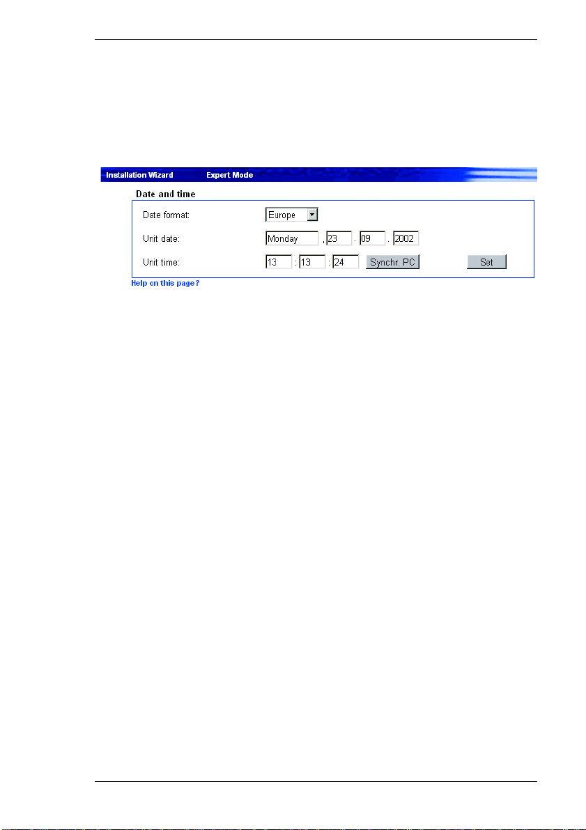
Chapter 7 Configuring the Receiver
Website language:
Select the language from the dropdown field.
Date and time
If a number of VIP units are part of a system, it is important that the internal clocks
of these separate units be synchronized. Only if all units operate with the same
time it is possible, for example, to correctly identify and evaluate recordings that
have been made simultaneously.
Date format:
Choose the desired date format here
(Europe: DD.MM.YYYY; USA: MM.DD.YYYY; Japan: YYYY/MM/DD).
Unit date:
Enter the current date here. Since the system time is controlled by the internal
clock, it is not necessary to enter the day of week. This is added automatically.
Unit time:
Enter the current time here or click the Synchr. PC button to copy the system
time of your computer to the VIP.
VIP 10 / VIP 1000 69
Page 70
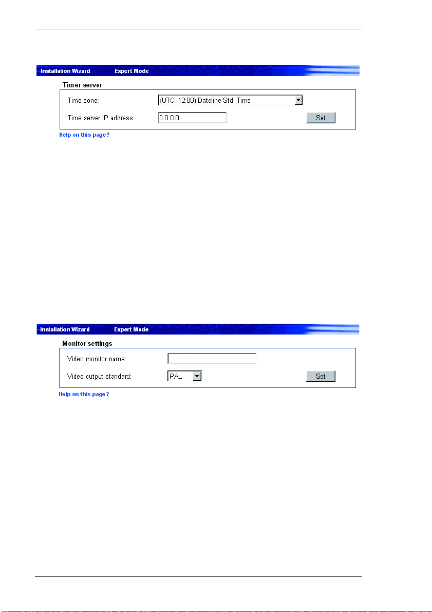
Configuring the Receiver Chapter 7
Timer server
The VIP can receive a time signal from a time server (NTP server) and use it to
set its internal clock. The device calls up the time signal automatically every two
hours.
Time zone:
Select the time zone that applies to your system.
Time server IP address:
Enter the IP address of the chosen NTP server here.
Monitor settings
The monitor name is used for easier identification of the monitor. It is used by
VIDOS, the VCS software for managing video surveillance systems, and makes
the task of identifying the monitor easier.
The video standard for the connected monitor can also be selected here.
Video monitor name:
Enter the desired monitor name here. Enter a unique, unambiguous name.
Video output standard:
Select the video standard for the monitor output.
70 VIP 10 / VIP 1000
Page 71
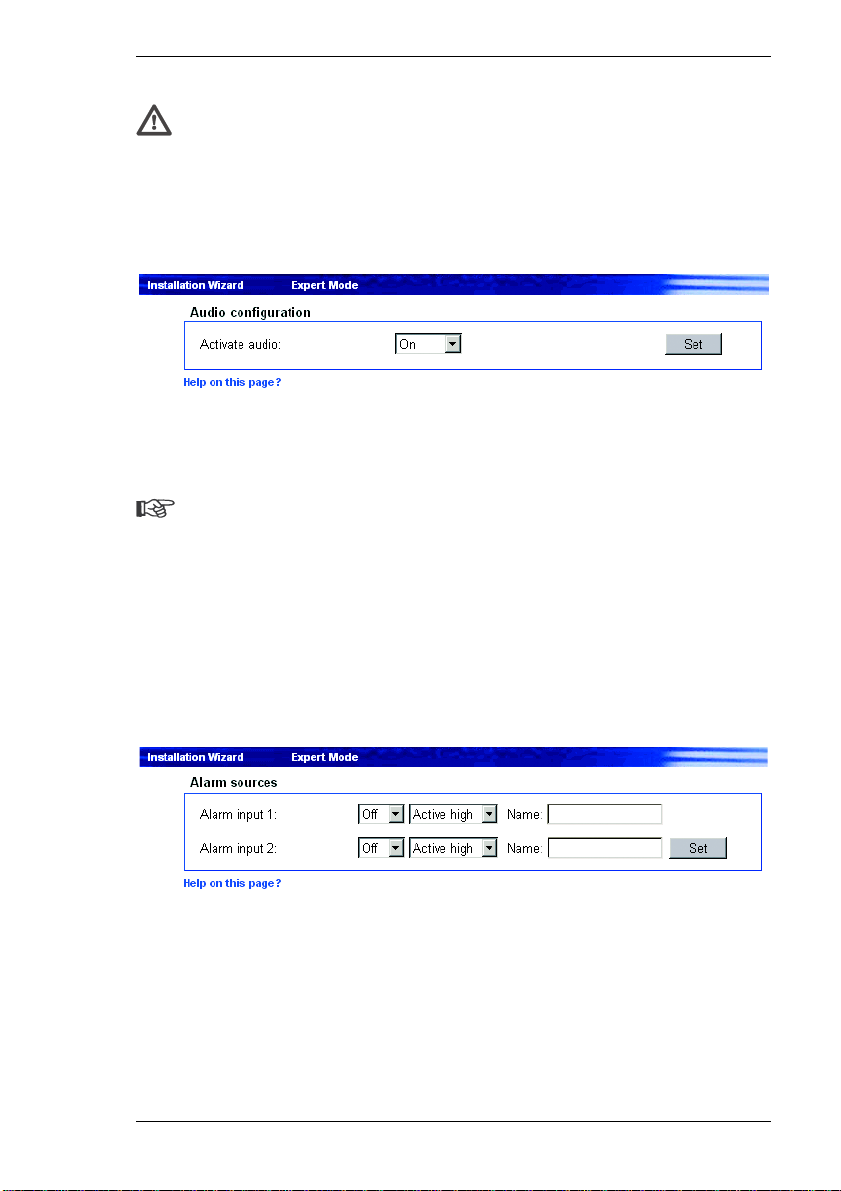
Chapter 7 Configuring the Receiver
Warning!
Be sure to choose the correct video standard to avoid damaging the
monitor.
Audio configuration
In addition to video data, the unit can also receive audio signals. Audio
transmission occurs parallel to video data transfer and requires an additional
bandwidth of about 80 kBit/s.
Note
Audio signals can only be received if the audio function is also enabled on
the transmitter (see page 46).
Activate audio: Select On to receive audio in addition to the video data.
Alarm sources
Both VIP alarm inputs can be configured individually.
Alarm input 1:
Select On if the alarm is to be activated by the external alarm sensor 1.
Furthermore, you can choose whether the alarm is to be activated by an Active
high or Active low voltage signal.
VIP 10 / VIP 1000 71
Page 72
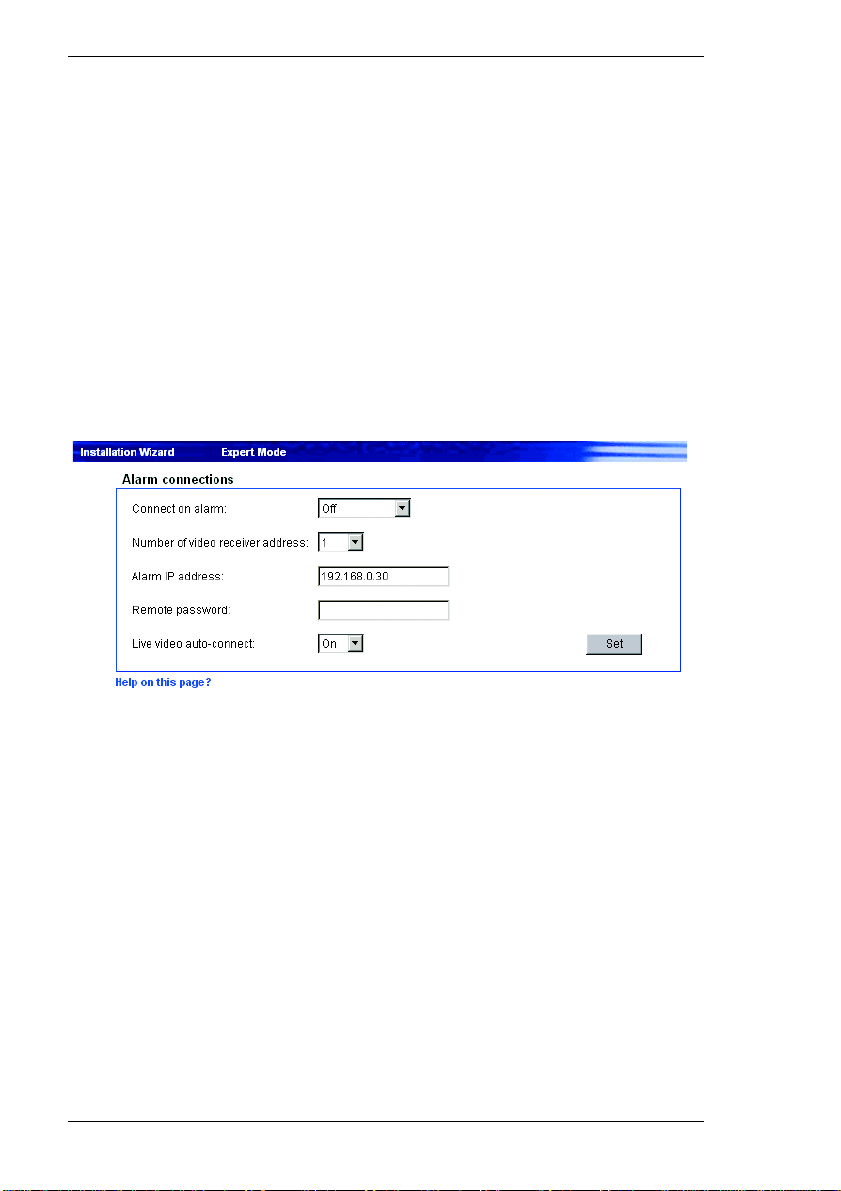
Configuring the Receiver Chapter 7
Enter a designation for the alarm input in the Name field. This name will be shown
on the transmitter's Livepage next to the associated alarm icon.
Alarm input 2:
Select On if the alarm is to be activated by the external alarm sensor 2.
Furthermore, you can choose whether the alarm is to be activated by an Active
high or Active low voltage signal.
Enter a designation for the alarm input in the Name field. This name will be shown
on the transmitter's Livepage next to the associated alarm icon.
Alarm connections
The VIP can be configured to connect to a specified remote location, such as a
transmitter, when an alarm is triggered.
Connect on alarm:
Select On, to establish a connection automatically to a specified IP address in the
event of an alarm.
With the setting Follows input 1, the VIP establishes an automatic connection to
a remote location as long as a signal is present at the alarm input 1. This setting
can also be used to connect two VIP units via a control switch. In this case, a
computer is not needed to establish the connection.
72 VIP 10 / VIP 1000
Page 73
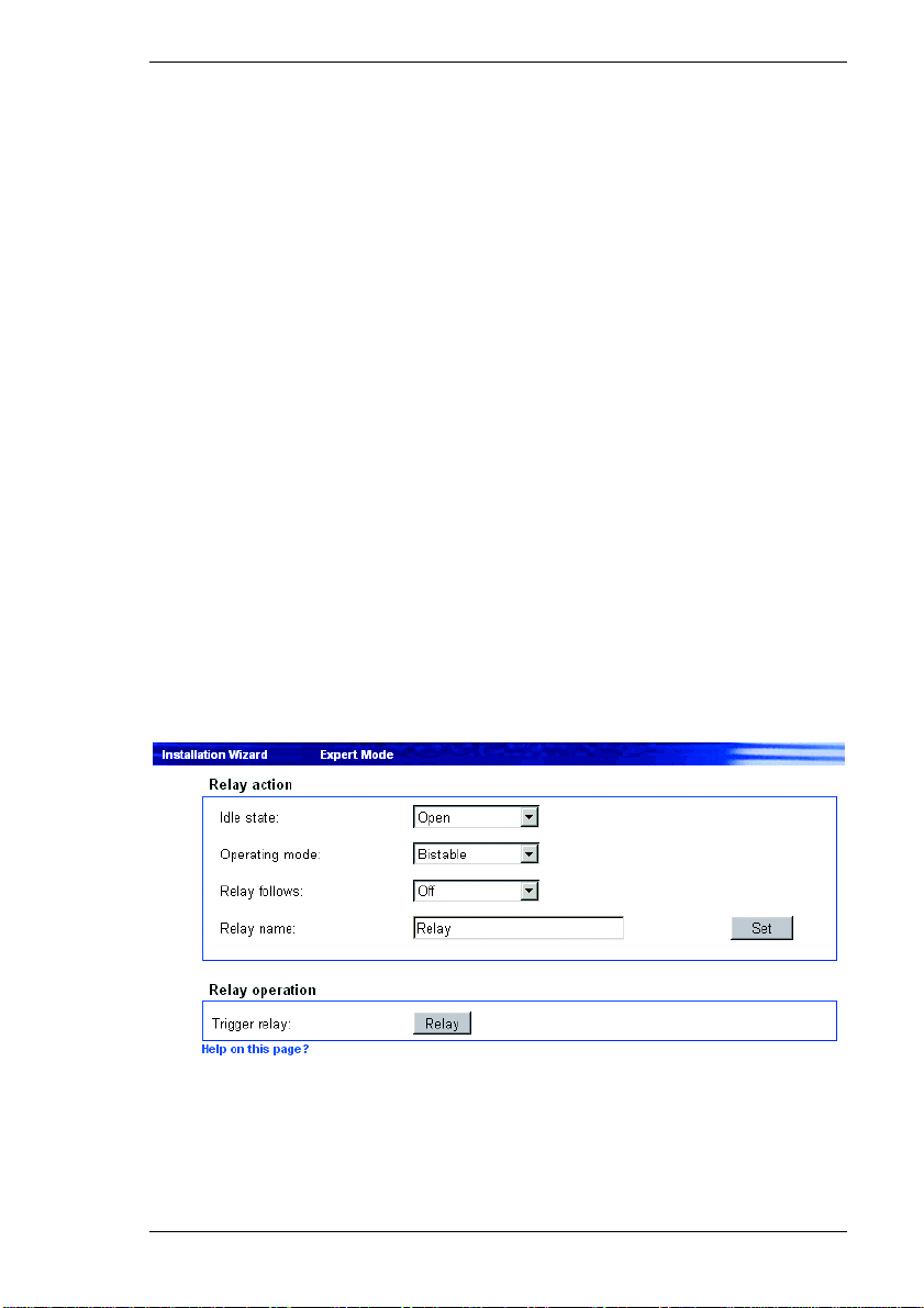
Chapter 7 Configuring the Receiver
Number of video receiver address:
The VIP can store up to 10 IP addresses, which are polled in response to an
alarm. When an alarm signal is received, the unit attempts to contact the first IP
address. If this address cannot be reached, the others will be tried in sequence
until a connection can be established. Select the contact priority of the IP address
here.
Alarm IP address:
Enter the IP address to contact in the event of an alarm.
Remote password:
Enter the password for the remote device (if it has one) that is to be contacted in
response to an alarm.
Live video auto-connect:
Select On here if an active connection should be established after each reboot,
for example following a connection failure or power failure.
Relay action / Relay operation
You can configure the switching behavior of the relay output. Open switch relay
mode (normally closed contact) or closed switch relay mode (normally open
contact) can be specified here.
VIP 10 / VIP 1000 73
Page 74

Configuring the Receiver Chapter 7
It is also possible to specify whether the output should react with an bistable
(permanent) or a monostable (time limited) signal. With a permanent signal
(bistable), the activated state of the relay is maintained. With a time limited signal
(monostable), the delay can be selected after which the relay reverts to its idle
state.
You can choose various events that activate the output automatically. In this way,
for example, it is possible to switch on an audible alarm when an alarm signal is
received via the connection and switch the audible alarm off again when the
alarm signal is no longer present.
Idle state:
Select Open if the relay is to operate as a normally open contact or Closed if it
is to operate as a normally closed contact.
Operating mode:
Select an operating mode for the relay.
If, for example, a lamp switched on by an alarm is to remain lit when the alarm
has ended, select Bistable. If an acoustic signal acti vated by an alarm is to soun d
for a period of ten seconds for example, select 10s.
Relay follows:
Select a particular event to trigger the relay. The following events can activate the
relay:
] Off No relay triggering by events
] Connection
Triggering whenever a connection is established
] Local input 1
Triggering by the alarm input 1
] Remote input 1
Triggering by a relay contact at a remote location (only when a connection is
established)
] Unified picture
Triggering caused by a lack of contrast in the picture
74 VIP 10 / VIP 1000
Page 75
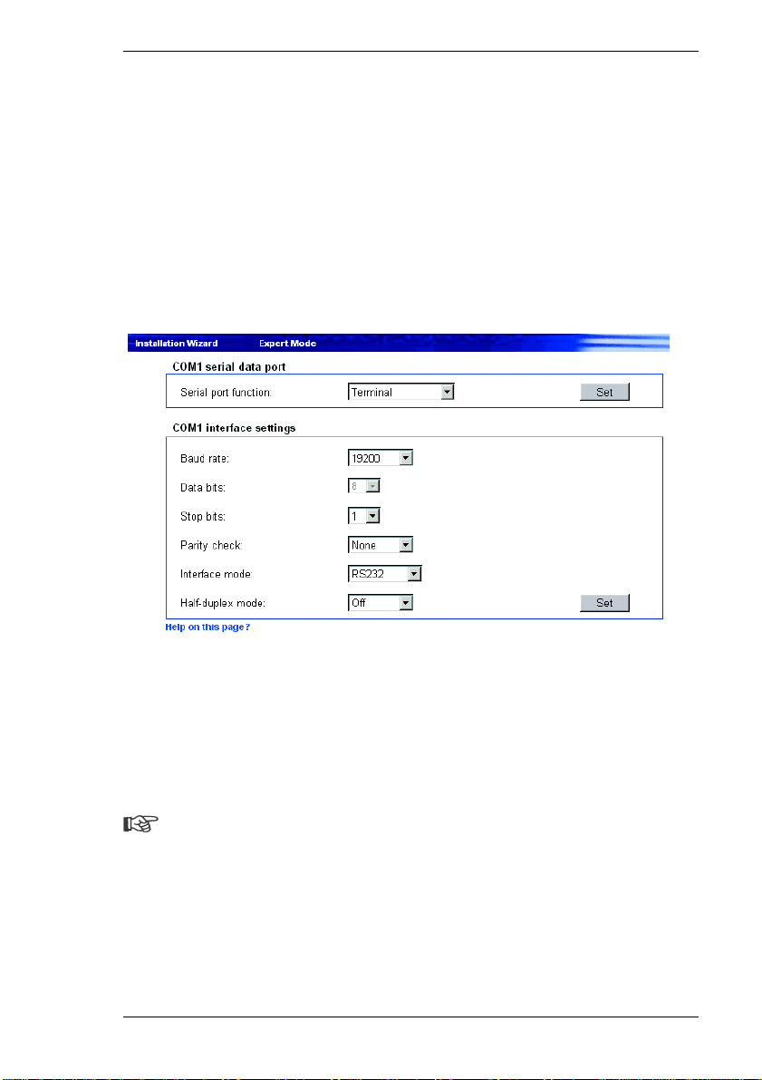
Chapter 7 Configuring the Receiver
Relay name:
The relay can be assigned a name here.
Trigger relay:
Click the button to switch the relay manually (for example for test purposes or to
operate a door opener).
COM1 serial data port / COM1 interface settings
The serial interface port RS232/485 can be configured for your specific
requirements.
Serial port function:
If you want to use the serial interface to transmit transparent data, select
Transparent. To operate the VIP with a terminal, choose Terminal.
Note
After selecting an interface function, the remaining parameters in the
window are set automatically and should not be altered.
Baud rate:
Select the value for the data communication rate in Bit/s.
VIP 10 / VIP 1000 75
Page 76
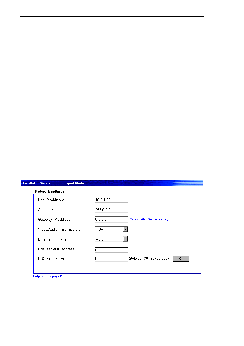
Configuring the Receiver Chapter 7
Data bits:
The number of data bits per character cannot be changed.
Stop bits:
Select the number of stop bits per character.
Parity check:
Select the type of parity check.
Interface mode:
Select the desired protocol for the serial interface.
Half-duplex mode:
Choose the setting that is appropriate for your application.
Network settings
The settings on this page are used to integrate the unit into an existing network.
76 VIP 10 / VIP 1000
Page 77

Chapter 7 Configuring the Receiver
Warning!
Although the modified network settings are copied to the VIP when the Set
button is clicked, they only become effective after the unit has been
restarted. To do this, enter the old IP address with /reset appended to it
in the address field of the Web browser. The unit will be accessible only at
its new IP address after this action.
Unit IP address:
Enter the desired IP address for the VIP in this field. The IP address must be
recognized by the network.
Subnet mask:
Enter the corresponding subnet mask here if the unit is to communicate via a
subnet.
Gateway IP address:
Enter the corresponding IP address here if the unit is to establish a connection
within the local network independently. Otherwise, this field can remain empty
(0.0.0.0).
Video/Audio transmission:
If the device is used in front of a firewall, TCP (Port 80) should be selected as the
transmission protocol. For use in a local network, choose UDP.
Warning!
Multicast operation is possible only with the UDP protocol. The TCP
protocol does not support multicast connections.
Ethernet link type:
Adjust here the ethernet link to the network. In most applications Auto is the
correct choice. For some routers and switches it can be necessary to set the
Ethernet link to a fixed value. In that case select the appropriate value:
] 10 MBit/s HD = 10 MBit/s half-duplex
] 10 MBit/s FD = 10 MBit/s full-duplex
VIP 10 / VIP 1000 77
Page 78

Configuring the Receiver Chapter 7
] 100 MBit/s HD = 100 MBit/s half-duplex
] 100 MBit/s FD = 100 MBit/s full-duplex
DNS Server IP address:
Working with a device over the Internet dynamic IP addresses are assigned for
efficient use of the IP address pool, i.e. the device gets a new (changing) IP
address each time a connection is set up.
Connecting is easier when the device is listed on a DNS server. The device logs
in regularly leaving the device name, device IP address and the current Internet
IP address. To connect to a device over the Internet you just insert the device
name together with the URL of the DNS server which then returns the valid
Internet IP address for automatic connection set up.
The default setting for the DNS server IP address is the IP address of the VCS
DNS server videotec.info. The VIP contacts the server automatically when a
refresh time is specified in the next parameter. If e.g. the name of the VIP is
myVIP just type myVIP.videotec.info as URL to set up a connection.
Note
Assign a unique name to the VIP if you want to use this feature.
DNS refresh time:
Enter here the time interval for the VIP to contact the DNS server. You can enter
a value from 30 to 86400 sec (24 h). Leave this field empty when you don't want
to use the DNS function.
Version information
The hardware and software version numbers are for information only and cannot
be altered. Keep a record of these numbers in case technical assistance is
required.
78 VIP 10 / VIP 1000
Page 79
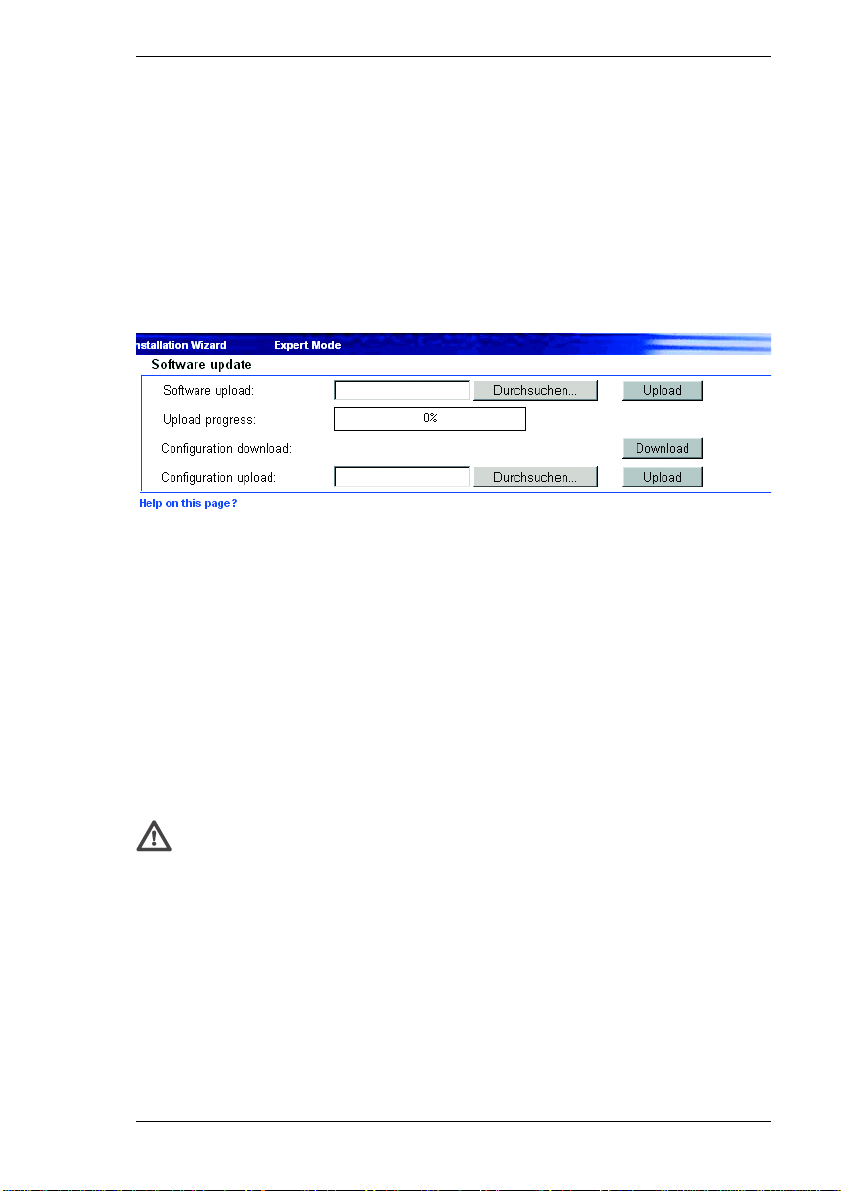
Chapter 7 Configuring the Receiver
Hardware version:
The hardware version number of the VIP is displayed.
Software version:
The software version number of the VIP is displayed.
Software update
Software upload:
The VIP is designed so its functions and parameters can be updated with
firmware. To do this, you transmit the latest firmware update to the unit via the
selected network. The firmware will be installed there automatically after the
connection is closed.
This allows a VIP unit to be serviced and updated remotely without intervention
by a technician to make on-site changes to the unit installation.
The latest firmware can be obtained from VCS Customer Service or downloaded
from the Internet at our Web site, www.vcs.com.
Warning!
Before starting the firmware upload, be certain that you have selected the
correct upload file! Uploading the wrong files can result in the unit no longer
being addressable, requiring it to be replaced. Never interrupt the
installation of the firmware. Interruption will damage the Flash EPROM.
This can also render the unit inoperable and make replacement necessary.
– First, save the update file to the hard disk.
– Enter the full root directory path for the update file in the field or click
Durchsuchen... to locate and select the file.
VIP 10 / VIP 1000 79
Page 80

Configuring the Receiver Chapter 7
– Click Upload to begin transmission to the unit. The transmission progress can
be monitored from the status messages and the progress bar.
After the upload is completed successfully, the unit will restart automatically.
If the operating status LED flashes red and green alternately, the upload has
failed and must be done again. This requires that you work from a special page:
– Enter the IP address of the unit in the browser and append /main.htm (for
example 192.168.0.12/main.htm).
– Repeat the upload.
Configuration download:
You can save the unit's configuration data to a PC.
– Click Download. A dialog box will appear.
– Follow the instructions in the dialog box to save the current settings.
Configuration upload:
You can upload configuration data that you previously saved to a PC, to the unit.
– Enter the full root directory path of the file to upload or click Durchsuchen...
to select the desired file.
– Make certain that the file you want to load is of the same type as the unit you
want to reconfigure.
– Click Upload to start transmitting the file to the unit.
This message will appear: Configuration upload finished. State:
Configuration upload ok (the system must be rebooted), and the
countdown for reconnection will be displayed.
– Restart the unit.
The next time the software update page is opened, the message Configuration
upload ok confirms the successful completion of the upload. If the message
Configuration upload failed is displayed, the file did not upload correctly.
Repeat the upload in this case, if necessary with a different file.
80 VIP 10 / VIP 1000
Page 81

Chapter 7 Configuring the Receiver
Function test
The VIP offers a variety of configuration options. Therefore you should check that
it works properly after installation and configuration. Only in this way can you
ensure that the VIP will also function properly in an alarm situation.
Check for the following (among other things):
] the VIP can be contacted remotely,
] the VIP transmits all the required data,
] the VIP responds as configured to alarm events and
] that any peripheral devices respond properly to control signals.
VIP 10 / VIP 1000 81
Page 82

Configuring the Receiver Chapter 7
82 VIP 10 / VIP 1000
Page 83
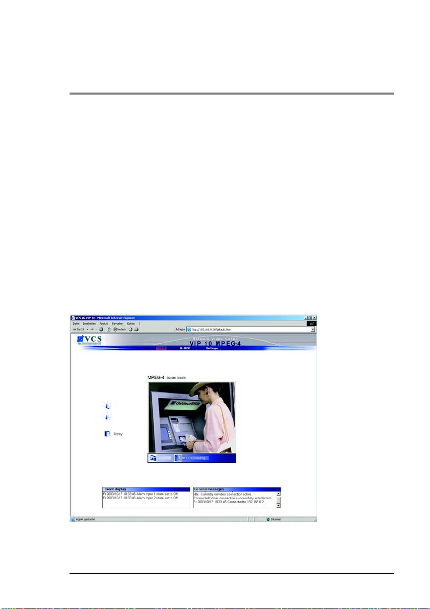
Transmitter Operation 8
Operation with Microsoft Internet Explorer
Various requirements must be met in order to operate with Internet Explorer.
Refer to the section entitled Establishing the connection in Chapter 5 (see
page 25).
The Livepage
After the connection is established, the Livepage will be displayed first. It shows
the live video image in the middle of the browser window. Depending upon
configuration, various text overlays may be visible on the image (see page 39).
Other information may also be shown next to the video image on the Livepage.
The display depends on the settings on the configuration page Livepage
configuration (see page 62).
VIP 10 / VIP 1000 83
Page 84

Transmitter Operation Chapter 8
Image quality
The VIP 10 displays either a live video sequence in MPEG-4 format or individual
live video frames in JPEG format. Moreover, with the VIP 1000 you can also call
up live video images in MPEG-2 format.
Note
Only the VIP 1000 provides live video images in MPEG-2 format.
– Click on the MPEG-4 or MPEG-2 link in the navigation bar at the top of the
browser display to display or decode the video sequences in the
corresponding image format.
or
– Click on the M-JPEG link in the navigation bar at the top of the browser display
to display or decode the individual frames in the corresponding image format.
– Click one of the links (352x288 or 704x576) above the live video image to view
the image in the chosen resolution.
Alarm
In the event of an alarm, a red alarm symbol is displayed next to the video image.
You can assign specific names to the alarm inputs. These will be shown next to
the relevant alarm symbols on the Livepage (see page 47).
Relay output
Depending upon configuration, a device such as a floodlight or a door opener can
be activated by the relay of the VIP unit. You can assign a specific name to the
relay. It will be shown next to the alarm symbol on the Livepage (see page 53).
– Click the relay symbol next to the video image to activate the relay output. The
symbol will turn red when the relay is activated.
Event messages
The Event display field is where events such as switching a relay or alarm status
messages are listed. These messages can be saved (see page 63).
84 VIP 10 / VIP 1000
Page 85
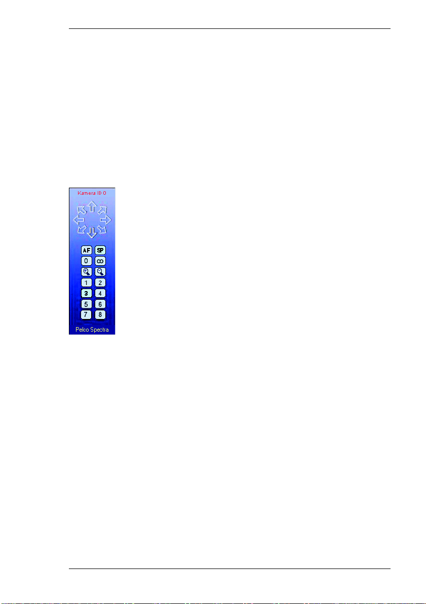
Chapter 8 Transmitter Operation
General messages
The General messages field contains information about the operating status of
the VIP and the connection. These messages can be saved (see page 64).
Control functions
Control options for peripheral devices (such as a pan and tilt head) depend on the
type of device installed and the configuration of the VIP.
If a controllable device (such as a dome camera) is configured and connected to
the VIP, the controls for the device are displayed next to the video image.
– To control a peripheral device click the appropriate operating elements.
– Move the pointer over the live video image. Further options for peripheral
device control will be displayed.
VIP 10 / VIP 1000 85
Page 86
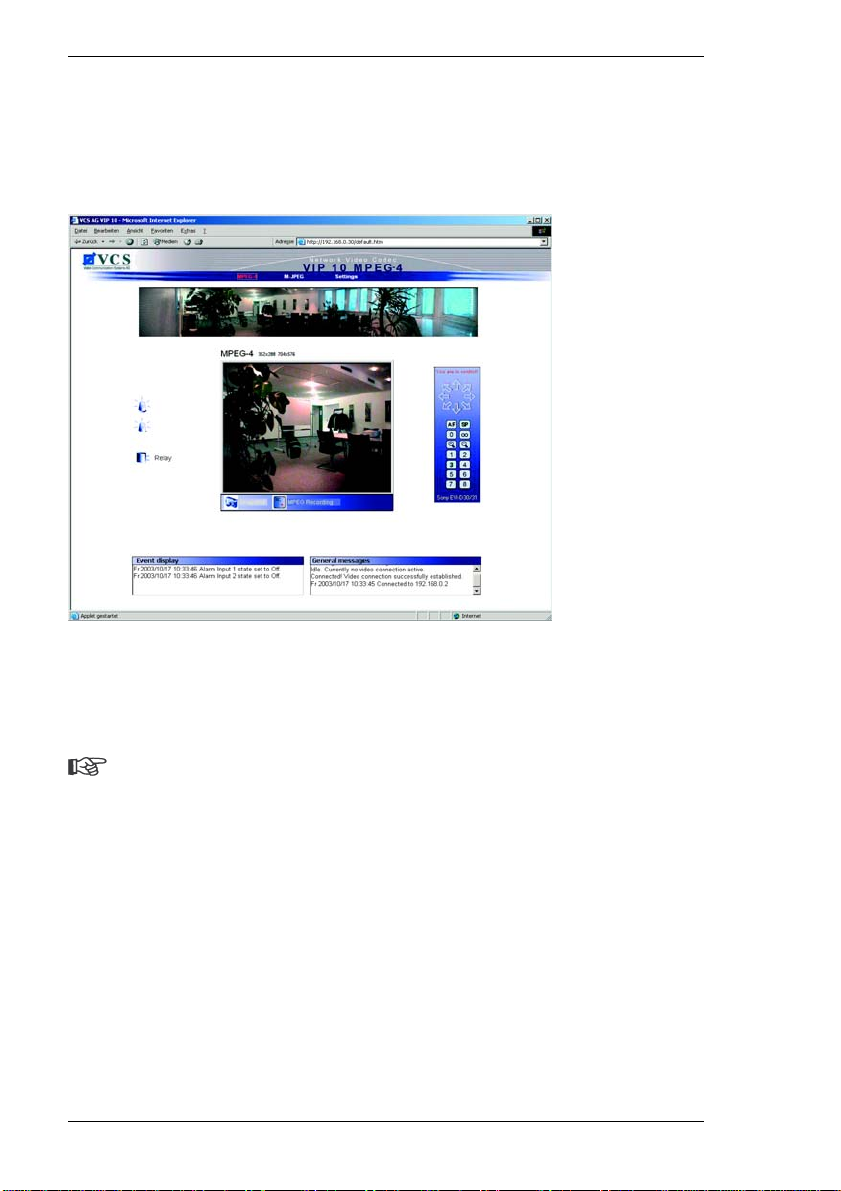
Transmitter Operation Chapter 8
Panorama view
If you are working with a Sony EVI-D100 or EVI-D30/31 camera, you can also
display a panoramic image. The panoramic image is shown in the upper part of
the Livepage. It consists of five single images that can be updated any time.
– Right-click on the panoramic image to open the context menu.
– Select Start scan to update the individual images. Stop scan cancels the
update.
Note
The panorama image is displayed only if Show panorama view is selected
on the configuration home page Livepage configurati on (see page 62).
86 VIP 10 / VIP 1000
Page 87

Chapter 8 Transmitter Operation
Saving snapshots
Individual images from the current video sequence on the Video Livepage can be
saved in JPEG format on the computer's hard drive.
– Click the Snapshot symbol. The image will be saved. The storage location
depends on the configuration of the VIP (see page 62).
Image resolution
Snapshots can be called up and displayed at different resolutions by entering
URL parameters in the address field of the Web browser. Just append the
corresponding parameter to the snap.jpg command:
] snap.jpg?JpegSize=S for 176 × 144 pixels
] snap.jpg?JpegSize=M for 352 × 288 pixels
] snap.jpg?JpegSize=XL for 704 × 576 pixels
Without the extra parameter, the default image size is 352 × 288 pixels.
– Type the IP address of the VIP, followed by /snap.jpg into the Internet
address field as URL (e.g. http://192.168.0.12/snap.jpg).
– Press the Return key or Enter key. A single frame image will be displayed in a
new window.
– Right-click the image and select Save Picture As... from the context menu.
– Save the snapshot in the desired format, giving it a new name.
VIP 10 / VIP 1000 87
Page 88

Transmitter Operation Chapter 8
Recording video sequences
You can manually save segments of the current video sequence displayed on the
Livepage to your hard drive. The video sequences will be stored in MPEG format.
– Click the MPEG Recording icon to start recording a sequence. The storage
location depends on the configuration of the VIP (see page 62).
Recording begins immediately. The red dot on the MPEG Recording icon
flashes while the recording is in progress.
– Click the icon once more to stop the recording.
Note
Use the VCS MPEG viewer to play the recorded video. The latest version
of the MPEG viewer is on the accompanying software CD. It is also
available from VCS Customer Service or as an Internet download at
www.vcs.com.
Image resolution
The sequences will be recorded at the resolution specified in the settings for the
corresponding encoder (see page 43 ). Select the encoder for Livepage video
display on the configuration page Livepage configu ration.
MPEG viewer installation
You will find the VCS MPEG viewer on the accompanying software CD.
– Insert the CD into the CD-ROM drive of the computer. The CD will start
automatically. If the CD does not start automatically, open it in Windows
Explorer.
– Open the directory entitled MPEG-Viewer and copy the MPEGViewer.exe file
to your hard drive.
– You can start the MPEG viewer by double-clicking the file
MPEGViewer.exe.
88 VIP 10 / VIP 1000
Page 89
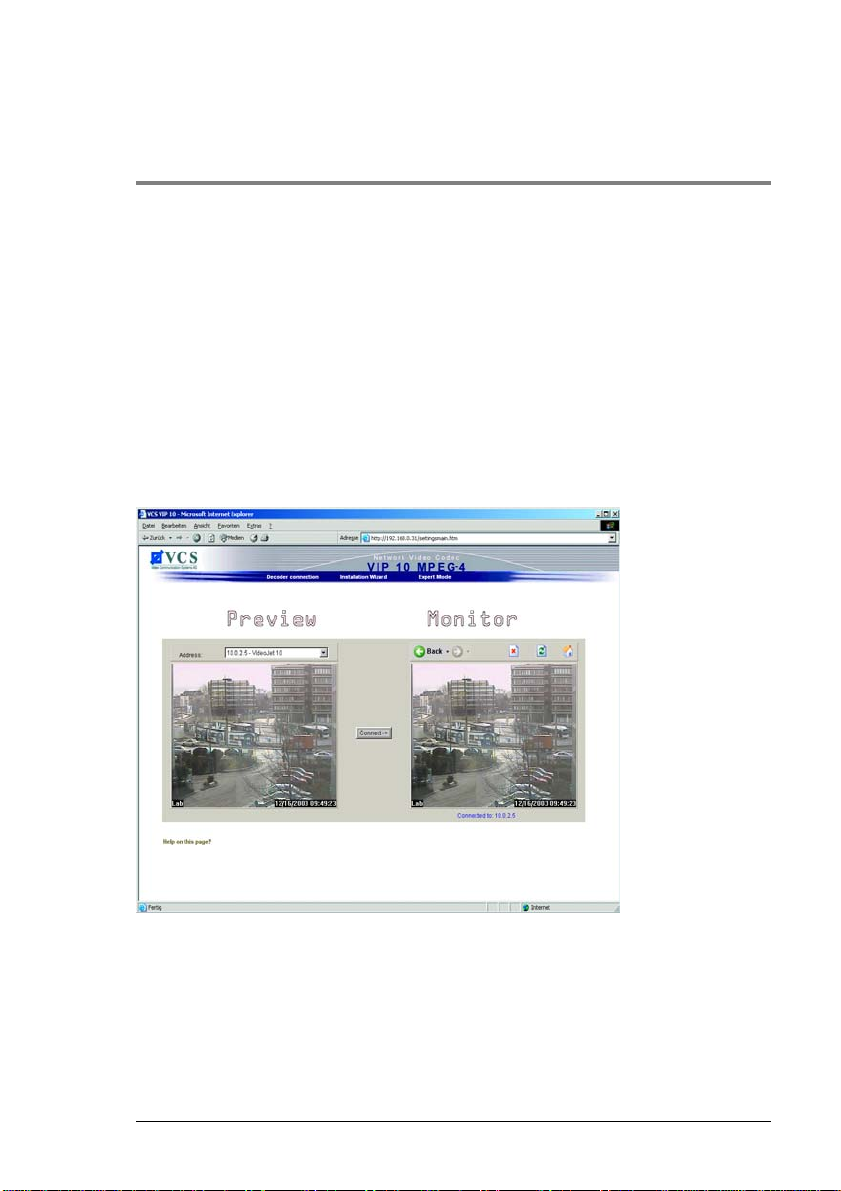
Receiver Operation 9
Operation with Microsoft Internet Explorer
Various requirements must be met in order to operate with Internet Explorer.
Refer to the section entitled Establishing the connection in Chapter 5 (see
page 25).
The Decoder connection page
After the connection has been established, the Decoder connection page will be
displayed.
Preview
This area displays a snapshot of the video image from the transmitter, which is
online at that moment. In addition to the unit name, the snapshot provides other
means of identifying the transmitter.
VIP 10 / VIP 1000 89
Page 90

Receiver Operation Chapter 9
Monitor
The video image currently seen on the connected monitor is shown here. As soon
as a connection is made to a transmitter, you will see the video image from the
selected transmitter here.
Connection between the receiver and transmitter
During startup the VIP automatically scans the network for available transmitters.
As soon as a transmitter is found on the network, the VIP connects to it
automatically. All the transmitters found are listed in a dropdown list labeled
Available sender units.
Establishing a connection
– Choose a transmitter from the list of Available sender units. A JPEG
snapshot from the video source selected will appear on the start page under
Preview.
– Click Connect to begin displaying the video images on the connected monitor.
The video image from the selected source can now also be seen under
Monitor.
Terminating a connection
– Click the icon with the red x to stop the video display on the monitor.
90 VIP 10 / VIP 1000
Page 91

Hardware Connections 10
Hardware connections between VIP units
A VIP transmitter, connected to a camera, and a VIP receiver, connected to a
monitor, can be linked together easily via an Ethernet network. This makes it
possible to establish connections over large distances with little effort for
installation or cabling.
Installation
The VIP units are designed to connect with one another automatically when
correspondingly configured. The only requirement is that they are both part of a
closed network. Proceed as follows to install the units:
– Connect the units to the closed network using Ethernet ca bles.
– Connect them to the mains supply.
Note
Make sure the units are correctly configured for the network environment
and that the transmitter setting for the Alarm IP address parameter is set
to the IP address of the video receiver (see page 48).
Establishing the connection
There are three options for establishing a connection between a VIP transmitter
and a VIP receiver in a closed network:
] when an alarm signal is given,
] using a terminal program or
] using a Web browser
VIP 10 / VIP 1000 91
Page 92

Hardware Connections Chapter 10
Connection when an alarm signal is given
The transmitter can be configured to connect automatically with a receiver when
an alarm is triggered (see page 48). After a short time, the live video image from
the transmitter will be shown on the monitor to which it is connected.
This option can also be used to connect two VIP units via a switch. In this case,
a computer is not needed to establish the connection (see page 72).
Connection using a terminal program This operating mode has various prerequisites. Refer to the section Setup using
terminal software in Chapter 4.
– Start the terminal program (see page 21). Enter the command I to call up the
IP menu.
– Enter the command r in the IP menu to change the remote IP address, then
enter the IP address of the device to connect to.
– Enter the command a in the IP menu to activate automatic connection set up.
Connection using a Web browser
This operational mode has various prerequisites. Refer to the section
Establishing the connection in Chapter 5 (see page 25).
– Use the Web browser to connect to the VIP receiver. Its home page will be
displayed.
– Select a transmitter from the Available sender units. A JPEG snapshot of the
selected video source will be displayed on the page.
– Click Connect to begin showing the video images on the monitor.
92 VIP 10 / VIP 1000
Page 93

Chapter 10 Hardware Connections
Closing the connection
The connection may be closed using a terminal program or Web browser.
Closing the connection using a terminal program
– Start the terminal program (see page 21); enter the command I to call up the
IP menu.
– Enter the command a in the IP menu to deactivate automatic connection.
Closing the connection using a Web browser
– Use the Web browser to connect to the VIP receiver. Its home page will be
displayed.
– Click the icon with the red x to stop the video display on the monitor.
VIP 10 / VIP 1000 93
Page 94

94 VIP 10 / VIP 1000
Page 95

Operation with Decoder Software 11
Operation with VIDOS
VIP video servers and VIDOS software can be combined to form a high performance system solution.
VIDOS is software for the operation, control and administration of CCTV
installations (e.g. surveillance systems) at remote locations. It runs under
Microsoft Windows operating systems. Its main function is decoding video, audio
and control data from a remote transmitter.
There are many options available for operation and configuration when using VIP
devices in combination with VIDOS. Refer to the software documentation for
more details.
VIP 10 / VIP 1000 95
Page 96

96 VIP 10 / VIP 1000
Page 97

Maintenance and Upgrades 12
Testing the network connection
The ping command can be used to check the connection between two IP
addresses. This allows you to test whether a unit is active in the network.
– Open the DOS command prompt.
–Type ping followed by the IP address of the unit.
If the unit is found, the response appears as Reply from ..., followed by the
number of bytes sent and the transmission time in milliseconds. Any other
response indicates that the unit cannot be accessed via the network. Possible
causes:
] The unit is not properly connected to the network. Check the cable
connections in this case.
] The unit is not correctly integrated into the ne tw o r k. C heck th e IP ad dress,
subnet mask and, if necessary, the gateway IP.
Device reset
The reset button can be used to reset the unit to its original factory settings. Any
changes in the settings will be overwritten by the factory defaults. This may be
necessary, for example, if the unit has invalid settings that prevent it from
functioning as desired.
Warning!
All configured settings will be discarded during a reset. If necessary, back
up the current settings using the Download button on the configuration
page entitled Software Update (see page 64 or page 79).
Before starting the firmware upload, be sure that you have selected the
correct upload file! Uploading the wrong files can result in the unit no longer
being addressable, requiring it to be replaced. Do not interrupt the firmware
installation for any reason! Interruption will damage the Flash EPROM. This
VIP 10 / VIP 1000 97
Page 98

Maintenance and Upgrades Chapter 12
can likewise result in the unit no longer being addressable, requiring it to be
replaced.
Note
After a reset, the unit can only be addressed via the factory default IP
addresses. The IP address can be changed as described in the chapter
entitled Installation (see page 22).
– If necessary, back up the current settings using the Download button on the
configuration page entitled Software Update.
– Disconnect the unit from the mains supply.
– Use a pointed object to press the reset button. All settings will revert to their
defaults.
– Change the IP address of the unit as necessary.
– Configure the unit to meet your requirements.
Repairs
Warning!
Never open the casing of the VIP device. The unit does not contain parts
that you can repair or replace.
Ensure that maintenance or repair work is performed only by qualified personnel
(electrical technicians), or contact your VCS dealer service center.
Transfer and disposal
The VIP should only be passed on together with this reference manual.
The unit and its power supply contain environmentally hazardous materials that
must be disposed of professionally as required by local law.
Defective or superfluous units and parts should be disposed of professionally or
taken to your local collection point for hazardous materials.
98 VIP 10 / VIP 1000
Page 99

Appendix 13
Troubleshooting
If a problem cannot be resolved, please contact VCS Customer Service
([email protected]).
The version numbers of the internal processors can be viewed on a special page.
Please note this information before contacting Customer Service.
– In the address field of the browser, append /version.htm to the IP address
of the unit (e.g . 192.168.0.12/version.htm) and press return.
– Write down the information or print out the page.
The following table is intended to help you identify the causes of malfunctions and
correct them where possible.
Problem Possible Causes Solution
No connection
between the unit and
terminal program.
No image
transmission from
the target location.
Faulty cable connections. Check all cables, plugs, contacts
The computer's serial
interface is not connected.
Interface parameters do not
match.
Defective camera. Connect a local monitor and check
Faulty cable connections. Check all cables, plugs, contacts
and connections.
Check the other serial interfaces.
Select a different COM port if
necessary and make sure that the
computer's interface parameters
match those of the unit. Yo u can also
try the following standard
parameters: 19,200 baud, 8 data
bits, no parity, 1 stop bit. After that,
switch off the power to the unit and
switch it on again after a couple of
seconds.
the camera function.
and connections.
VIP 10 / VIP 1000 99
Page 100

Appendix Chapter 13
Problem Possible Causes Solution
No connection
established, no
image transmission.
No audio
transmission from
the target location.
The unit does not
report an alarm.
Control of cameras
or other devices is
not possible.
The unit is no longer
operational after a
firmware upload.
The unit's configuration. Check all settings.
Faulty installation. Check all cables, plugs, contacts
Wrong IP address. Check the IP addresses (terminal
Faulty data transmission
within the LAN.
The maximum number of
connections possible to
other devices has already
been reached.
Hardware failure. Check that all audio devices
Faulty cable connections. Check all cables, plugs, contacts
Faulty configuration. Check the audio settings (volume
Audio/voice communication
is busy with another
receiver.
No alarm source is chosen. Select alarm input on the Alarm
No alarm action selected. Define the desired alarm actions on
The cable connection
between the serial interface
and the connected device is
incorrect.
The interface parameters
conflict with those of the
other device connected.
Power failure when
uploading the update file.
and connections.
program).
Check data transmission with the
ping command.
Wait until there is a free connection
and contact the transmitter again.
connected function correctly.
and connections.
and coding mode).
Wait until a connection is available
and contact the transmitter again.
sources configuration page.
the Alarm connections
configuration page. If necessary,
change the IP address.
Check all cable connections and
ensure all plugs are properly
plugged in.
Make sure the settings of all devices
involved are compatible.
Replace the unit and have it
checked by VCS.
100 VIP 10 / VIP 1000
 Loading...