

Page 1
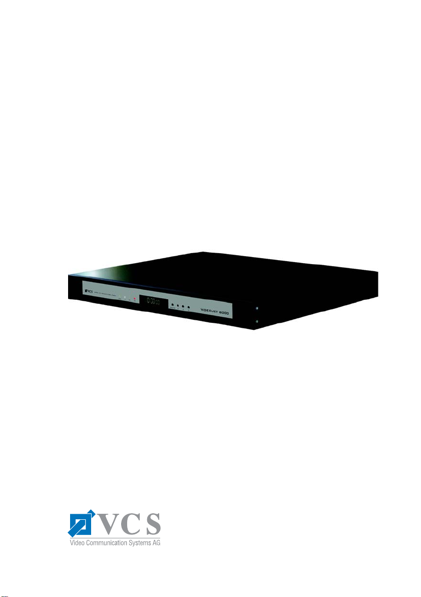
VideoJet 8000
User Guide
Page 2

Copyright
This user guide is the intellectual property of VCS and is protected by copyright.
All rights reserved. No part of this document may be reproduced or transmitted
for any purpose, by whatever means, electronic or mechanical, without the
express written permission of VCS.
Release: August 2004 (Software version 1.1)
Copyright © 2004 VCS Video Communication Systems AG
Note
This user guide has been compile d w it h great care, and the information it
contains has been thoroughly verified. The text was complete and correct at the
time of printing. Due to further product development, the contents of the user
guide may change without prior notice. VCS accepts no liability for damages
resulting directly or indirectly from errors, omissions or discrepancies between
the user guide and the product described.
Trademarks
All hardware and software product names used in this document are believed to
be trademarks or registered trademarks of their respective owners and must be
treated accordingly.
Page 3

Contents
Contents 0
Chapter 1 Preface
Conventions. . . . . . . . . . . . . . . . . . . . . . . . . . . . . . . . . . . . . . . . . . 5
Intended use . . . . . . . . . . . . . . . . . . . . . . . . . . . . . . . . . . . . . . . . . 6
EU guidelines. . . . . . . . . . . . . . . . . . . . . . . . . . . . . . . . . . . . . . . . . 6
Rating label . . . . . . . . . . . . . . . . . . . . . . . . . . . . . . . . . . . . . . . . . . 6
Chapter 2 Safety Information
Electrical shock hazard . . . . . . . . . . . . . . . . . . . . . . . . . . . . . . . . . 7
Installation and operation. . . . . . . . . . . . . . . . . . . . . . . . . . . . . . . . 8
Maintenance and repair. . . . . . . . . . . . . . . . . . . . . . . . . . . . . . . . . 8
Chapter 3 Product Description
Supplied components . . . . . . . . . . . . . . . . . . . . . . . . . . . . . . . . . . 9
System requirements for setup . . . . . . . . . . . . . . . . . . . . . . . . . . . 9
Configuration requirements . . . . . . . . . . . . . . . . . . . . . . . . . . . . . 10
Operational requirements . . . . . . . . . . . . . . . . . . . . . . . . . . . . . . 10
Overview of functions . . . . . . . . . . . . . . . . . . . . . . . . . . . . . . . . . 11
Rear panel connectors. . . . . . . . . . . . . . . . . . . . . . . . . . . . . . . . . 14
Front panel. . . . . . . . . . . . . . . . . . . . . . . . . . . . . . . . . . . . . . . . . . 15
Chapter 4 Installation
Control cabinet installation. . . . . . . . . . . . . . . . . . . . . . . . . . . . . . 18
Connections. . . . . . . . . . . . . . . . . . . . . . . . . . . . . . . . . . . . . . . . . 20
Switching on/off . . . . . . . . . . . . . . . . . . . . . . . . . . . . . . . . . . . . . . 22
Setup using a terminal program. . . . . . . . . . . . . . . . . . . . . . . . . . 23
Chapter 5 Configuration using a Web Browser
Connecting. . . . . . . . . . . . . . . . . . . . . . . . . . . . . . . . . . . . . . . . . . 27
Choosing the configuration mode . . . . . . . . . . . . . . . . . . . . . . . . 29
Installation Wizard . . . . . . . . . . . . . . . . . . . . . . . . . . . . . . . . . . . . 31
Device overview. . . . . . . . . . . . . . . . . . . . . . . . . . . . . . . . . . . . . . 34
Expert Mode . . . . . . . . . . . . . . . . . . . . . . . . . . . . . . . . . . . . . . . . 71
Function test . . . . . . . . . . . . . . . . . . . . . . . . . . . . . . . . . . . . . . . 111
VideoJet 8000 3
Page 4

Contents
Chapter 6 Operation
Operation with Microsoft Internet Explorer . . . . . . . . . . . . . . . . 113
Saving snapshots . . . . . . . . . . . . . . . . . . . . . . . . . . . . . . . . . . . 118
Recording video sequences . . . . . . . . . . . . . . . . . . . . . . . . . . . 1 18
Recordings in progress . . . . . . . . . . . . . . . . . . . . . . . . . . . . . . . 119
Playback of recorded sequences . . . . . . . . . . . . . . . . . . . . . . . 120
Backup . . . . . . . . . . . . . . . . . . . . . . . . . . . . . . . . . . . . . . . . . . . 122
MPEG viewer installation . . . . . . . . . . . . . . . . . . . . . . . . . . . . . 123
Hardware connections between VCS units. . . . . . . . . . . . . . . . 124
Establishing the connection. . . . . . . . . . . . . . . . . . . . . . . . . . . . 124
Closing the connection . . . . . . . . . . . . . . . . . . . . . . . . . . . . . . . 126
Operation with decoder software. . . . . . . . . . . . . . . . . . . . . . . . 126
Front panel controls. . . . . . . . . . . . . . . . . . . . . . . . . . . . . . . . . . 127
Chapter 7 Maintenance and Upgrades
Testing the network connection. . . . . . . . . . . . . . . . . . . . . . . . . 131
Repairs . . . . . . . . . . . . . . . . . . . . . . . . . . . . . . . . . . . . . . . . . . . 131
Transfer and disposal . . . . . . . . . . . . . . . . . . . . . . . . . . . . . . . . 132
Chapter 8 Appendix
Troubleshooting. . . . . . . . . . . . . . . . . . . . . . . . . . . . . . . . . . . . . 133
LEDs . . . . . . . . . . . . . . . . . . . . . . . . . . . . . . . . . . . . . . . . . . . . . 135
RS232/RS422/RS485 interface. . . . . . . . . . . . . . . . . . . . . . . . . 136
Glossary . . . . . . . . . . . . . . . . . . . . . . . . . . . . . . . . . . . . . . . . . . 137
Specifications . . . . . . . . . . . . . . . . . . . . . . . . . . . . . . . . . . . . . . 139
Chapter 9 Index
4 VideoJet 8000
Page 5

Preface 1
This user guide is intended for persons responsible for the installation and
operation of VideoJet 8000. International, national and any regional regula tions
regarding electronics must be followed at all times. The user manual describes
the installation and operation of the unit.
Conventions
In this manual, the following symbols and notation are used to draw attention to
special situations:
Warning!
This symbol indicates that failure to follow the safety instructions described
may endanger persons and cause damage to the unit or other equipment.
It is associated with immediate, direct hazards.
Note
This symbol indicates tips and information for easier, more convenient use
of the unit.
VideoJet 8000 5
Page 6

Preface Chapter 1
Intended use
The VideoJet 8000 network video server transmits video and control signals over
data networks (such as Ethernet LANs and the Internet). The integrated hard
drive enables the VideoJet 8000 to be used as a DVR. It is designed for use in
CCTV systems. By incorporating external alarm devices, various functions can
be triggered automatically. Other applications are not permitted.
In the event of questions concerning the use of the server which are not answered
in this manual, please contact your local dealer or:
VCS Video Communication Systems AG
Forchheimer Strasse 4
90425 Nuremberg, Germany
Phone: +49 (0)911 9 34 56-0
Fax: +49 (0)911 9 34 56-66
EU guidelines
The VideoJet 8000 network video server complies with the specifications of EU
Directives 89/336 (Electromagnetic Compatibility) and 73/23, amended by 93/68
(Low Voltage Directive).
Rating label
For exact identification of the unit, the model and serial number are inscribed on
the rating plate on the botto m of th e housing. Please note this information if
necessary before installation so it available in case of questions or spare parts
orders.
6 VideoJet 8000
Page 7

Safety Information 2
Electrical shock hazard
] Never attempt to connect the un it to any power net work other than the type for
which it was intended.
] Never open the casing!
] If a fault occurs, disconnect the unit from the mains supply and from all other
devices.
] Install the unit only in dry, weather-protected areas.
] If safe operation of the unit cannot be ensured, remove it from service and
secure it to prevent unauthorized start-up. Safe operation is no longer
possible, for example,
– if there is visible damage to the unit or power cables,
– if the unit no longer works properly,
– if the unit has been exposed to rain or moisture,
– if foreign matter has infiltrated the unit,
– after long storage under adverse conditions or
– after exposure to extraordinary transport stress.
In such cases, have the unit checked by VCS.
VideoJet 8000 7
Page 8

Safety Information Chapter 2
Installation and operation
] Relevant electrical codes and guidelines must be complied with at all times
during installation.
] Before installing or operating the unit, make sure you have read and
understood the documentation for the other equipment connected to the
system, such as cameras. It contains important safety instructions and
information about permitted uses.
] Perform only the installation and operating steps described in this manual.
Actions beyond these may lead to personal injuries, property damage or
damage to the equipment.
Maintenance and repair
] Never open the casing of the VideoJet 8000 yourself, there are no user
serviceable parts inside.
] Ensure that all maintenance or repair work is performed only by qualified
personnel (electrical technicians).
8 VideoJet 8000
Page 9

Product Description 3
Supplied components
] Network video serverVideoJet 8000
] Power cable
] RS232 null modem cable
] Mounting kit for installation in 19" racks
] The quick start guide “First Steps” in English and German
] VCS product CD with the following content:
– The quick start guide “First Steps” in English and German
– User guide in English and German
– MPEG-ActiveX control from VCS
– MPEG viewer (DVD player)
– DirectX control
– Microsoft Internet Explorer
– Microsoft Virtual Machine
– Adobe Acrobat Reader
] 3.5" hard drive
System requirements for setup
] Computer with Microsoft Windows 98/2000/XP operating system and network
access and
] Microsoft Internet Explorer (version 5.5 or later) or
an available serial port and terminal software
VideoJet 8000 9
Page 10

Product Description Chapter 3
Configuration requirements
] Computer with Microsoft Windows 98/2000/XP operating system and network
access and
] Microsoft Internet Explorer (version 5.5 or later) or decoder software, such as
VIDOS from VCS
Note
Make sure the graphic card is set to 16 or 32 bit color depth and the
Microsoft Virtual Machine is installed on your computer. If necessary, the
required software and controls can be installed from the CD provided (see
the list of components supplied, 9).
Operational requirements
] Computer with Microsoft Windows 98/2000/XP operating system and network
access and
] Microsoft Internet Explorer (version 5.5 or later) or decoder software, such as
VIDOS from VCS
or
] MPEG-2 capable hardware decoder from VCS (such as VIP 1000) as a
receiver and a connected video monitor
Note
Make sure the graphic card for receiving on the computer monitor is set to
16 or 32 bit color depth and the Microsoft Virtual Machine is installed on the
computer. If necessary, the required software and controls can be installed
from the CD provided (see the list of components supplied, 9).
10 VideoJet 8000
Page 11

Chapter 3 Product Description
Overview of functions
Network video server
The VideoJet 8000 is a network video server for 8 independent video channels.
Its primary function is to encode video and control data for transmission over an
IP network. The VideoJet 8000 encodes up to 8 nonmultiplexed data streams in
MPEG-2 format (DVD standard) and does so without compromising image
quality. The use of existing networks means that integration with CCTV systems
or local networks can be achieved quickly and easily.
The VideoJet 8000 is designed for tabletop operation and installation in control
cabinets. The supplied mounting kit makes installation in a 19" rack fast and easy.
Two units, a VideoJet 8000 as the transmitter and a VIP 1000 as the receiver,
can form a stand-alone system for data transfer without a PC. The system can be
expanded to include additional transmitters and receivers so that video images
from one transmitter can be received simultaneously on a number of receivers.
Receiver
Receivers can be MPEG-2 capable hardware decoders from VCS (such as the
VIP 1000), computers with decoding software installed, such as VIDOS from
VCS, or Microsoft Internet Explorer.
Video encoding/multicast
The VideoJet 8000 works with the MPEG-2 video compression standard. Thanks
to efficient encoding, the data rate remains low even with high image quality and
can also be adapted to local conditions with great flexibility. It can do this while
supporting simultaneous encoding on all 8 video channels.
In suitably configured networks, the multicast function enables simultaneous, real
time transmission to multiple receivers. The prerequisite for this is that the UDP
and IGMP protocols be implemented on the network.
DVR
The integrated hard drive enables the VideoJet 8000 to be used as a digital video
recorder for local long-term recording. Replay and backup are possible while
recording is in process (triplex function).
VideoJet 8000 1 1
Page 12

Product Description Chapter 3
The VideoJet 8000 supports ANR technology, which ensures seamless, gap-free
storage with the VIDOS-NVR, the network video recorder from VCS, even when
the network fails.
Remote control
The VideoJet 8000 can remotely control external devices, such as pan and tilt
heads or motorized zoom lenses, by transmitting control data via its bidirectional
serial interface. This interface can also be used to transmit transparent data.
Configuration
The VideoJet 8000 can be configured with a browser on the local network
(Intranet) or from the Internet.
Similarly, firmware updates and rapid loading of equipment configurations are
also possible.
Snapshots
Individual video frames (snapshots) can be called up in JPEG format by the
VideoJet 8000, stored on the computer hard drive or be displayed in a separate
browser window.
Backup
Video sequences can be saved to the computer's hard drive from either the live
video page or the local hard drive mode with just a mouse-click.
12 VideoJet 8000
Page 13

Chapter 3 Product Description
Summary
The main functions of the VideoJet 8000 can be summarized as follows:
] Video and data transmission over IP data networks
] Multicast function for simultaneous picture transmission to multiple receivers
] 8 independent, analog BNC video inputs FBAS (PAL/NTSC)
] Video encoding using the MPEG-2 (DVD quality) international standard
] Integrated Ethernet interface (10/100/1000 Base-T)
] Integrated ISDN connection (for future functional extensions)
] USB interface (for future functional extensions)
] Transparent, bidirectional data channel using a serial interface:
RS232, RS422 or RS485
] Local long-term recording on the integrated 3.5" hard drive
] Remote control of all built-in functions via TCP/IP
] Password protection to prevent unauthorized connection or configuration
changes
] 10 relay inputs for external sensors (such as door contacts)
] Event-driven, automatic connection in case of an alarm
] Integrated video sensor for motion alarms
] Video signal monitoring
] Fast, convenient configuration using a Web browser
] Firmware update through flash memory
VideoJet 8000 13
Page 14
Product Description Chapter 3
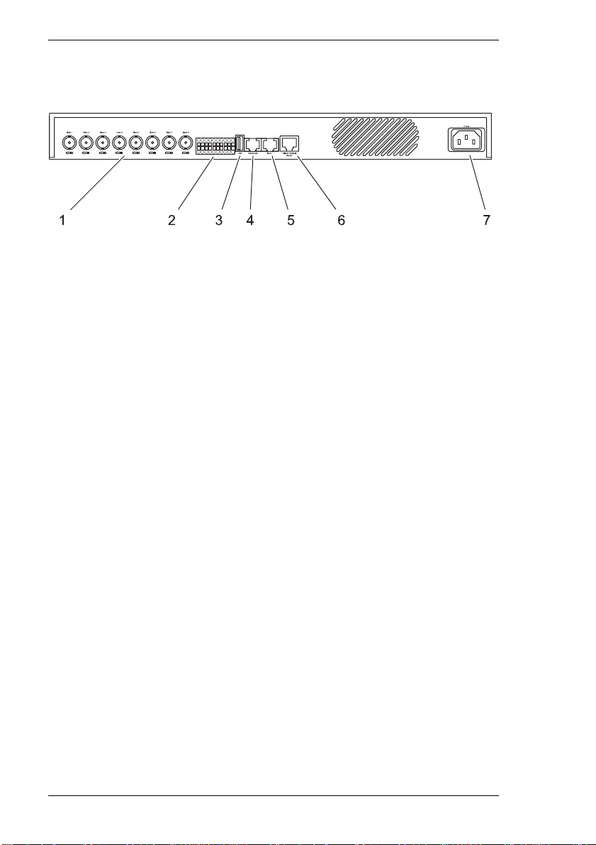
Rear panel connectors
1 8 video inputs, Video 1 to Video 8
BNC jacks for connecting video sources,
each with a switch for 75 ohm terminating resistance
2 10 alarm inputs, IN
1 ... IN10
push-in terminals for connecting external signal sources or switches
3USB port
for future functional extensions
4 RS232/485 serial interface
RJ45 jack for transmitting control data (RS232, RS422 and RS485 protocols)
and for configuration with terminal software
5 RJ45 jack for ISDN
for future functional extensions
6 RJ45 jack 10/100/1000 MBit Base-T
for connecting to an Ethernet LAN
7Power receptacle
for connecting the power cable
14 VideoJet 8000
Page 15
Chapter 3 Product Description
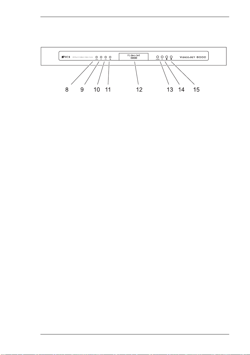
Front panel
8Power LED
lit green when ready for operation
9IR diode
infrared receiver (for future functional extensions)
10 HDD LED
blinks red duringdata transfer from and to the hard drive
11 Failure LED
blinks red in the event of a hardware error
12 Display
for showing the operating parameters
13 Menu/Exit button
for showing or hiding the configuration menu
14 Set button
for saving changes to the operating parameters
(for future functional extensions)
15 Arrow keys
for navigation in the configuration menu
Further information on the LEDs can be found on page 135.
VideoJet 8000 15
Page 16

Product Description Chapter 3
16 VideoJet 8000
Page 17

Installation 4
The VideoJet 8000 is designed for tabletop operation and installation in control
cabinets. The supplied mounting kit makes installation in a 19" rack fast and easy.
Four self-adhesive, anti-slip rubber feet are included with delivery. These can be
attached to the bottom of the unit.
Warning!
The unit is intended for indoor use only. Choose a suitable location for
installation where the equipment will not be subject to extremes of
temperature or humidity. The ambient temperature must be between 0 and
+50 °C. The relative humidity should not exceed 80% (no condensation).
The unit generates heat during operation. Ensure that there is adequate
ventilation and also that there is enough clearance between the unit and
heat-sensitive objects or equipment.
Please ensure the following conditions for installation:
] Do not mount the unit close to heaters or other heat sources. Avoid locations
in direct sunlight.
] Allow sufficient space for running cables.
] Ensure that the unit has adequate ventilation. For cabinet installation of
multiple units, pay particular attention to the overall thermal load.
] Use only the cables supplied for connection, or appropriate cables resistant to
electromagnetic interference.
] Position and run all cables so that they are protected from damage, and
provide strain relief where needed.
VideoJet 8000 17
Page 18

Installation Chapter 4
Control cabinet installation
The VideoJet 8000 is ready for installation in a 19" rack. The necessary mounting
kit is included with the delivery.
Warning!
When installing in cabinets, ensure that each unit has adequate ventilation.
The free space around the unit must be at least 5 cm on the right and left
sides and at least 10 cm in the back.
The ambient temperature must be between 0 and +50 °C. The relative
humidity should not exceed 80%.
The unit generates heat during operation. Ensure that there is enough
clearance between the unit and heat-sensitive objects or equipment.
When installing additional units, direct contact with the VideoJet 8000 is
permitted if the surface temperature of the adjacent units does not exceed
+50 °C.
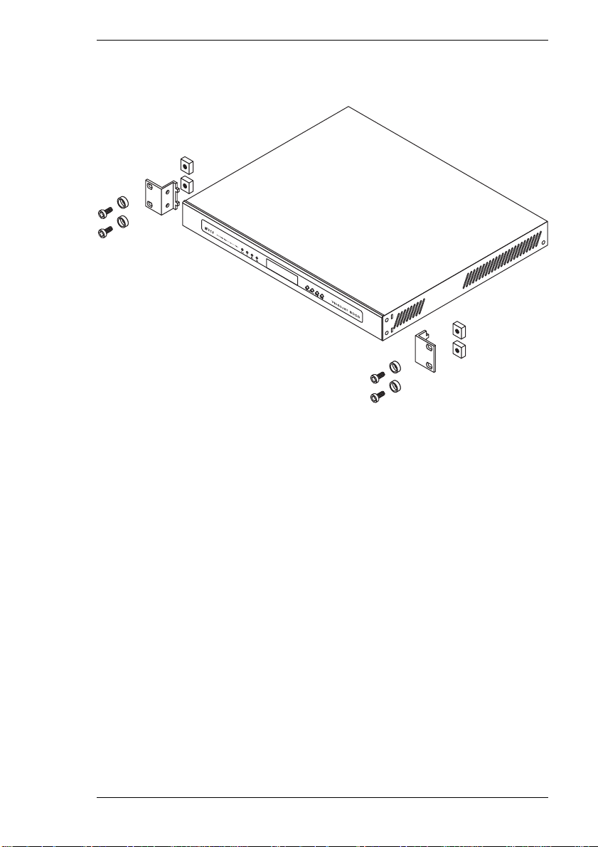
Unit installation
– Remove both screws on the front part of the right and left sides of the unit.
– Place both brackets from the mounting kit in the recesses by the screw holes
on the housing and attach them firmly using the four screws.
– Set the unit in the cabinet and attach the brackets to the frame using the four
screws, washers and lock nuts included in the kit.
– Insert the connector of the power cable in the power receptacle on the rear
side of the unit.
18 VideoJet 8000
Page 19
Chapter 4 Installation
Installation overview
VideoJet 8000 19
Page 20

Installation Chapter 4
Connections
Cameras
Up to 8 standard video sources (CCTV cameras) can be connected to the
VideoJet 8000. Any cameras or other video sources that produce a standard PAL
or NTSC signal are suitable for connection.
– Connect each of the cameras or other video sources with a video cable (75
ohm) to the BNC jacks Video 1 to Video 8.
– Set the slide switch (75 Ω) under the BNC jack to O to terminate the video
input if the signal is not passed on further.
Network
The VideoJet 8000 can be connected to a 10/100/1000 Base-T network directly
or via a hub. Use a standard UTP Category 5 cable with RJ45 connectors for this.
– Attach the network cable to the 10/100/1000 MBit Base-T jack.
Alarm inputs
The alarm inputs are used to connect to external alarm devices, such as door
contacts or sensors. Given the appropriate configuration, an alarm generator can,
for example, trigger an automatic connection between the VideoJet 8000 and a
remote location.
A voltage free closing contact or switch can be used as an actuator.
Note
Use a bounce-free contact system as the actuator if at all possible.
– Remove the terminal block from its receptacle.
– Connect the lines to the terminals and check that the connections are secure.
– Reconnect the terminal block to the unit.
20 VideoJet 8000
Page 21
Chapter 4 Installation
Data interface
The bidirectional data interface is used to control connected devices, such as a
dome camera with a motorized lens. During setup the interface is used to connect
to the data terminal using the RS232 protocol.
The interface supports RS232, RS422 and RS485 transmission protocols.
The selection of controllable devices is growing constantly. The manufacturers of
this equipment can provide specific information on installation and control.
Warning!
Make use of the device documentation when installing and operating a
device to be controlled. It contains important safety instructions and
information about permitted uses.
Note
The transmission of transparent data is only possible when a connection
has been established.
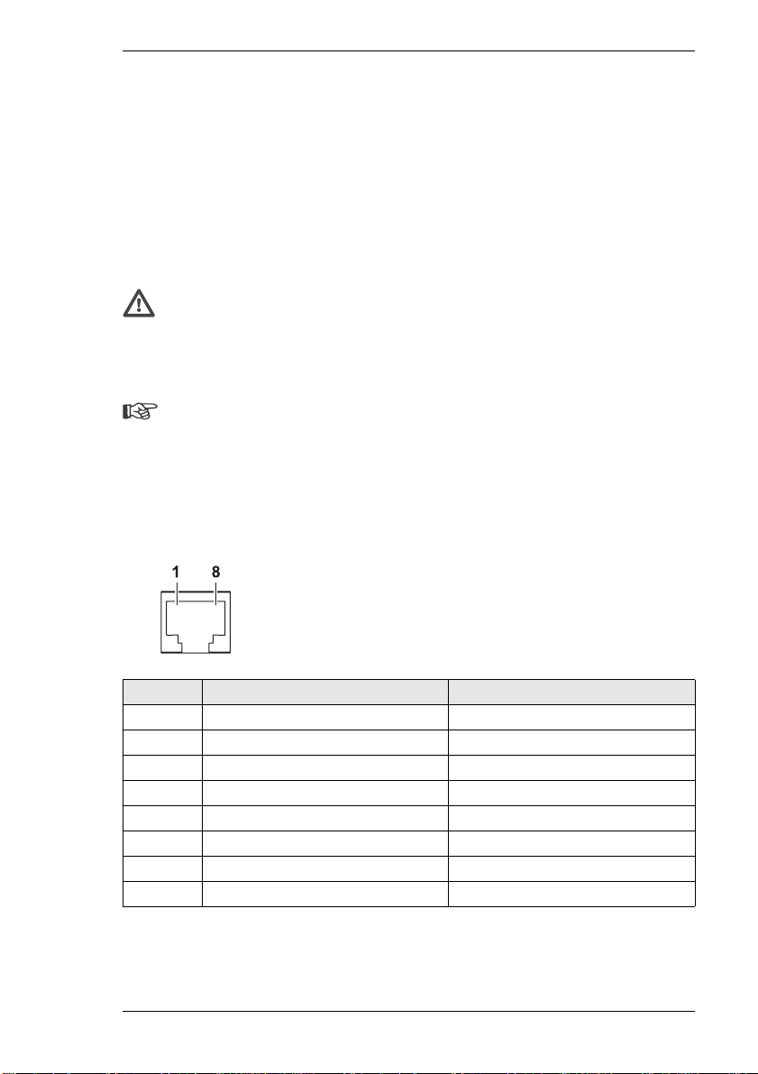
RJ45 connector pin assignments
The pin assignments depend on the protocol used.
Pin RS232 Protocol RS422/485 Protocol
1 RxD (receive data) RxD+ (receive data plus)
2 CTS (clear to send) RxD- (receive data minus)
3– –
4– –
5 GND (ground) GND (ground)
6– –
7 TxD (transmit data) TxD- (transmit data minus)
8 RTS (ready to send) TxD+ (transmit data plus)
VideoJet 8000 21
Page 22

Installation Chapter 4
Switching on/off
Power connection
The VideoJet 8000 package includes a power cable with a computer style
receptacle.
Warning!
Use suitable facilities where necessary to ensure that the mains supply is
free of interference such as voltage surges, spikes or brownouts. Only
connect the VideoJet 8000 to the mains supply after all other connections
have been established.
The VideoJet 8000 has no power switch. When the unit is connected to power, it
is ready for operation after startup.
– Attach the connector of the power cable to the Power socket.
– Plug the power cable into a fused power socket. The green Power LED on the
front panel of the VideoJet 8000 should be lit.
– After startup, the unit is ready for operation when "VideoJet 8000" appears on
the display.
If the network connection is in order, the green LED for the RJ45 jack
10/100/100 MBit Base-T on the back of the unit should be lit. The flashing orange
LED indicates data traffic on the network.
22 VideoJet 8000
Page 23

Chapter 4 Installation
Setup using a terminal program
Data terminal
A data terminal may be connected to the VideoJet 8000 for setup and local
control. The data terminal usually consists of a computer with suitable terminal
software. A serial cable is provided with the delivery for making the connection.
HyperTerminal, a communications accessory included with Microsoft Windows,
can be used as the terminal program.
Note
Information on installing and using of HyperTerminal can be found in the
user guides or online help for Microsoft Windows.
– Before working with the terminal program, disconnect the VideoJet 8000 from
the data network.
– Connect the RS232/485 RJ45 connector of the VideoJet 8000 to an available
serial port on the computer.
Configuring the terminal
To establish communication between the terminal program and the
VideoJet 8000, the transmission parameters must be defined properly. The
following values should be set in the terminal program:
] 19,200 Bit/s
] 8 data bits
] No parity check
] 1 stop bit
] No protocol
Command entry
After the connection has been established, you must enter a user name. After
that you can access the main menu. You can call up additional submenus and
functions using the on-screen commands.
– If necessary, turn off the local echo so that entered values are not repeated on
the screen display.
VideoJet 8000 23
Page 24
Installation Chapter 4
– Enter only one command at a time.
– After entering a value (such as an IP address), re-check the entry before
pressing the Enter key to send the data to the VideoJet 8000.
Assigning an IP address
To operate the VideoJet 8000 on a network, an IP address valid for the network
must be provided.
The following default address has been pre-set at the factory: 192.168.0.1
Note
The new addresses will only be in effect after restarting.
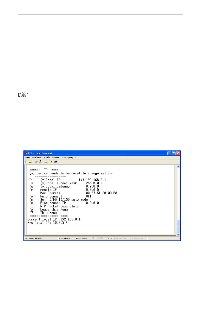
– Start up a terminal program such as HyperTerminal.
– First enter ? and then service as the user. The main menu will be
displayed.
– Enter the command i twice, in order to open the IP menu and then display the
current IP address.
– Enter the desired IP address and press Enter. The new IP address will be
shown.
– If necessary, enter the command s and a new subnet mask.
– Interrupt the power to the VideoJet 8000 briefly (pull the power plug and
replace it after a few seconds) to restart the unit.
24 VideoJet 8000
Page 25

Chapter 4 Installation
Additional parameters
Using the terminal program, you can check other basic parameters and modify
them where necessary. Use the on-screen commands displayed in the various
submenus for this purpose.
VideoJet 8000 25
Page 26

Installation Chapter 4
26 VideoJet 8000
Page 27

Configuration using a Web Browser 5
Connecting
The integrated HTTP server allows the unit to be configured over the network
using a Web browser. This option offers far more possibilities and is more
convenient than configuration using terminal software. It also allows live video to
be displayed.
Note
In order for the computer to decode live video images, the special ActiveX
control must be installed. The latest version of the ActiveX control can be
obtained from VCS customer service or from the download pages on the
Internet site at www.vcs.com.
Make sure the graphic card is set to 16 or 32 bit color depth and the
Microsoft Virtual Machine is installed on your computer. If necessary, the
required software and controls can be installed from the CD provided (see
the list of components supplied, 9).
Instructions for using the Web browser will be found in its online help.
System requirements
] Microsoft Internet Explorer (version 5.5 or higher)
] Monitor resolution 1024 × 768 pixels
] Network access (intranet or Internet)
MPEG decoder installation
Note
In order to decode MPEG encoded video data, an appropriate MPEG
decoder must be installed on the computer, such as that used for playing
DVD movies. If necessary, the required software and controls can be
installed from the CD provided (see the list of components supplied, 9).
VideoJet 8000 27
Page 28
Configuration using a Web Browser Chapter 5
– Insert the CD into the CD-ROM drive of the computer. The CD will start
automatically. If the CD does not start automatically, open the root directory of
the CD in Windows Explorer and double click MPEGAx.exe.
– Follow the instructions on the screen.
Establishing the connection
The VideoJet 8000 must be provided with a valid IP address to operate on your
network.
The following default address has been pre-set at the factory: 192.168.0.1
– Start the Web browser.
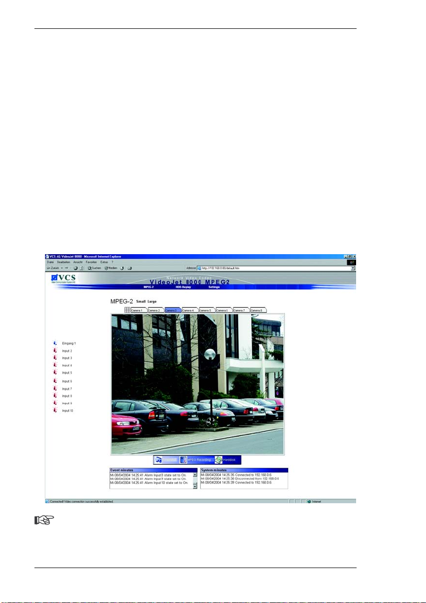
– Enter the IP address of the VideoJet 8000 as the URL. The connection will be
established, and after a short time the Livepage with the video image will
appear.
Note
If the connection cannot be established, this may be because the unit
selected is already busy with another remote station. Depending upon the
28 VideoJet 8000
Page 29

Chapter 5 Configuration using a Web Browser
network configuration and the individual units, a transmitter can serve up to
five receivers at the same time.
VideoJet 8000 password protection
If the VideoJet 8000 is password-protected against unauthorized access, a
password dialog will appear first.
Note
Configuration work can only be performed on a password-protected
VideoJet 8000 unit if the service user is logged on.
– Enter the user name and the associated password in the appropriate fields.
– Click OK. If the password is entered correctly, the Livepage with the video
image will be shown.
Choosing the configuration mode
There are various options for configuring the VideoJet 8000 or checking the
current setup:
] the Installation Wizard,
] the overview and
] expert mode.
All settings are stored in the VideoJet 8000 memory, and they are preserved
even if the power is interrupted.
Installation Wizard
The installation wizard is recommended for initial setup of the unit. It takes you
step by step through the necessary settings. This ensures that key settings for
proper operation are not overlooked. Moreover, each step offers brief instructions
that help with installation.
Device overview
The most important parameters can be displayed in groups for a quick overview.
The settings can also be changed here. However, a sequence is not specified
here.
VideoJet 8000 29
Page 30
Configuration using a Web Browser Chapter 5
Expert mode
Expert mode is recommended only for experienced operators or system
administrators. All unit parameters can be accessed in this mode. Operations that
affect the basic functionality of the unit (such as software updates) can only be
performed in expert mode.
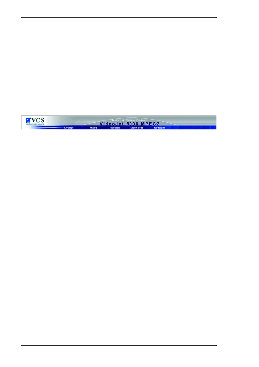
Beginning configuration
Click the Settings link in the top part of the Livepage. A new page will be opened,
and the required installation mode can be selected on the menu line:
30 VideoJet 8000
Page 31
Chapter 5 Configuration using a Web Browser
Installation Wizard
The VideoJet 8000 Installation Wizard guides you step by step through the
necessary settings.
Starting the Installation Wizard
The Installation Wizard can be started by clicking the Settings link on the
Livepage.
– Click the Installation Wizard link. A new page will appear.
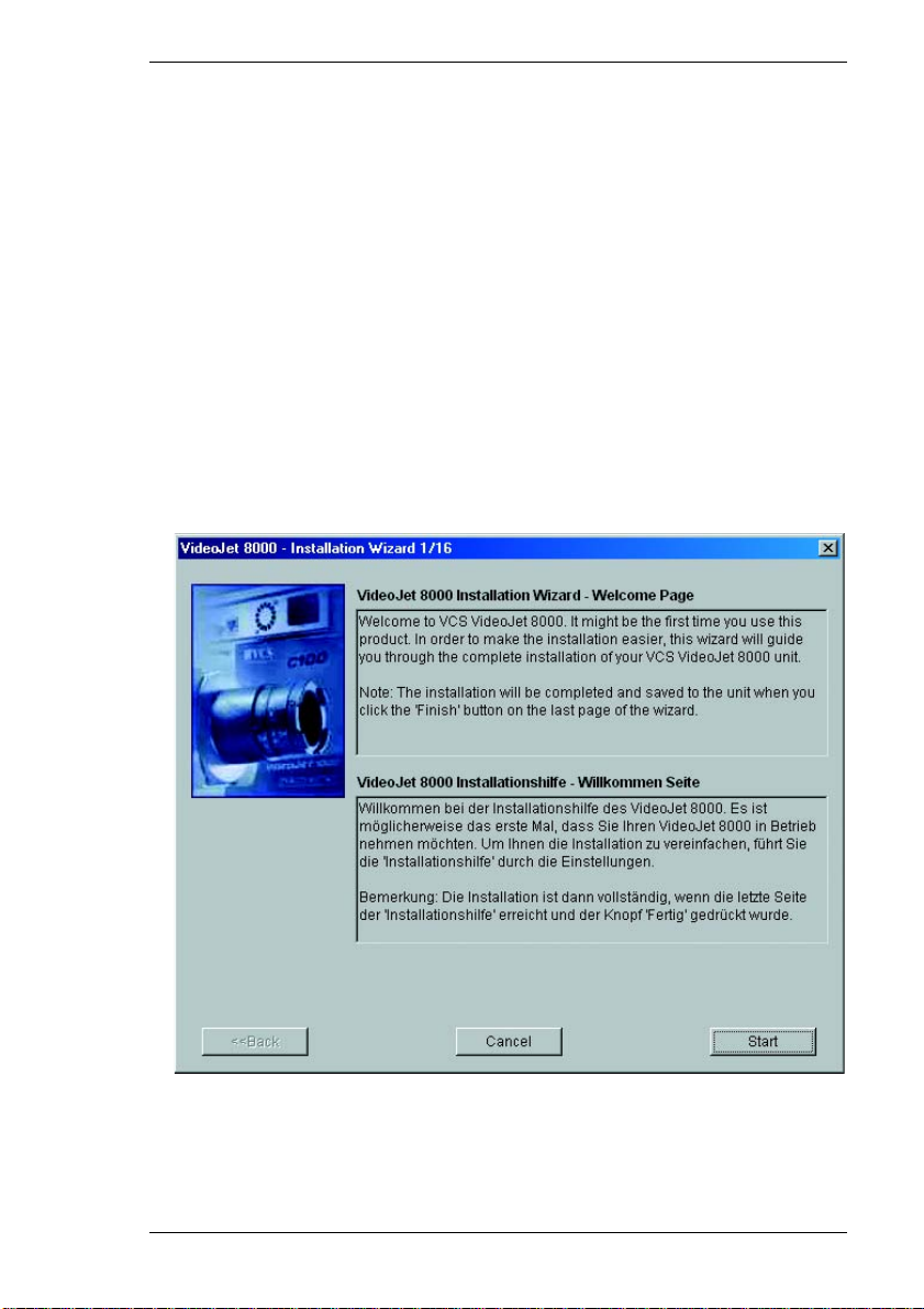
– Click the button with the wizard icon in the Installation Wizard field. The
Installation Wizard will be opened to the first page.
– Click Start to begin the wizard. The next page of the installation wizard will
appear:
VideoJet 8000 31
Page 32
Configuration using a Web Browser Chapter 5
General procedure
The pages of the Installation Wizard will be shown in sequence, allowing you to
work comfortably. The upper part of the page always contains information about
the settings options The current settings are shown in the lower area. You can
change settings by entering the desired value in a text field or choosing it from a
list. The navigation buttons for the Installation Wizard are at the bottom of the
window. You can switch between pages of the Wizard at any time .
– Always read the information in the upper part of the window first.
– Click in the text fields to enter values or use the other controls available, such
as buttons, check boxes or list fields.
– Click Next >> to go to the next step.
– Click << Back to look at the previous step again.
– Click Cancel to interrupt the process and close the Installation Wizard.
Applying the changes
Changes made with the Installation Wizard only take effect after the Finish
button on the last page is clicked.
Clicking Cancel causes the original settings to remain unchanged.
Warning!
Always continue with the Installation Wizard until the last page is reached.
Only there is it possible to save the changes by clicking Finish.
32 VideoJet 8000
Page 33
Chapter 5 Configuration using a Web Browser
Other settings
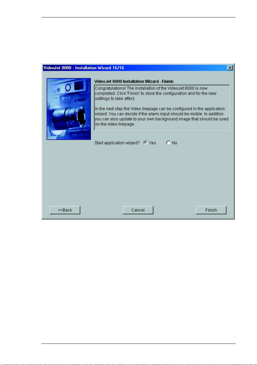
The last page of the Installation Wizard offers the option to start the Application
Wizard for configuring the Livepage.
– Click Yes to start the Application Wizard.
– Click Finish to close the Installation Wizard. The settings will be saved and
loaded on the VideoJet 8000, and the Application Wizard will start immediately
thereafter.
It works similar to the Installation Wizard.
VideoJet 8000 33
Page 34
Configuration using a Web Browser Chapter 5
Device overview
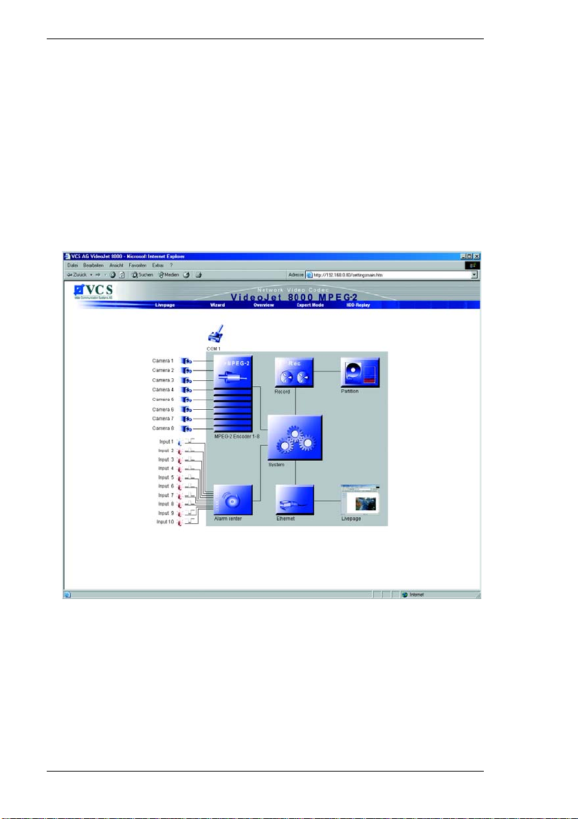
The device overview gives you a graphical overview to review the individual
areas of the configuration. The individual configuration parameters are grouped
and displayed in separate windows.
Opening the overview
The graphical overview can be accessed by clicking Settings on the Livepage.
– Click the Overview link. The page with the graphical overview will appear.
34 VideoJet 8000
Page 35
Chapter 5 Configuration using a Web Browser
General procedure
After the page with the graphical overview is opened, the individual setting groups
can be accessed directly.
– Click one of the group graphics. A new window will open.
– Click in the text fields to enter values or use the other controls available, such
as buttons, check boxes or list fields.
– Click the close button (X ) in the window title bar to close the window without
saving the changes.
Applying changes
After making changes in a window, click Set to load the new settings on the
device and save them there.
Warning!
Save the changes made in each window by clicking Set. When Set is
clicked, only the changes in that particular window are saved.
A description of the individual windows that can be accessed via the group
graphics of the overview is given below.
VideoJet 8000 35
Page 36
Configuration using a Web Browser Chapter 5
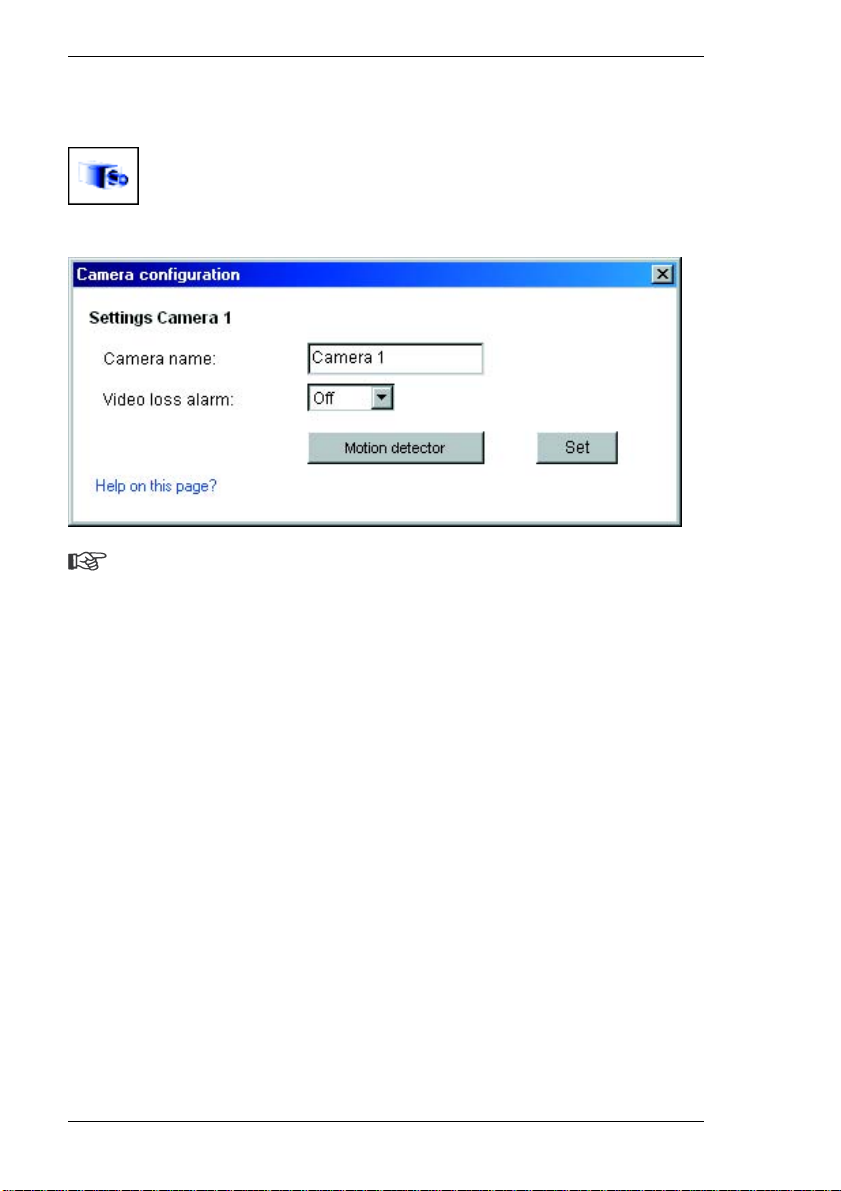
Camera configuration
Note
Each camera input must be configured separately. To do this, click the
camera icons one after another. The configuration page is identical for all
the inputs.
Camera name:
Enter the desired camera name here. The camera name makes it easier to
identify the remote camera location, in the event of an alarm for example. The
camera name will also be shown on the video image if so specified in the
configuration (see page 76). It is also used by VIDOS, the VCS software for
administering video monitoring systems. The camera name helps to identify the
camera or its location in the program. Enter an unambiguous, understandable
name in the field.
Video loss alarm:
Select On to monitor the video source (camera). If the signal is not present, the
VideoJet 8000 triggers an alarm.
36 VideoJet 8000
Page 37
Chapter 5 Configuration using a Web Browser
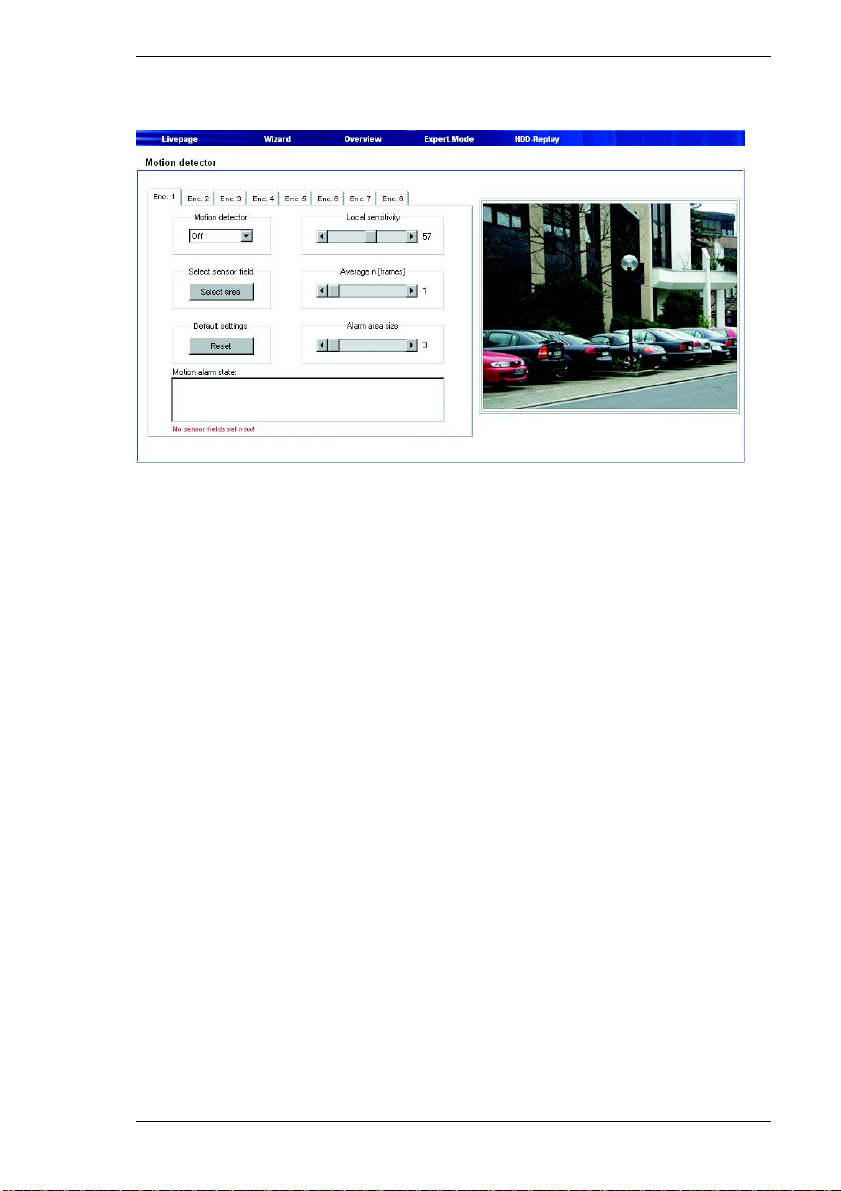
Motion detector
The VideoJet 8000 has an integrated video sensor which can detect changes in
the signal. Such changes are due primarily to movements in the camera's field of
view.
The video sensor can be configured separately for each encoder, i.e. for each
camera connected.
The sensitivity of the video sensor can be adjusted, so an alarm is generated only
if specified values are exceeded.
In order for the sensor to function, the following conditions must be met:
] The motion detector must be enabled.
] At least one cell must be activated.
] The individual parameters must be set for the operating environment and the
desired responses configured accordingly.
] The sensitivity must be set to a value greater than zero.
VideoJet 8000 37
Page 38

Configuration using a Web Browser Chapter 5
Warning!
Reflections of light (on glass surfaces, etc.), switching lights on or off or
changes in the light level caused by cloud movement on a sunny day can
trigger unintended responses from the video sensor and generate false
alarms. Run a series of tests under day and night conditions to ensure that
the sensor works as intended.
For indoor surveillance, ensure constant lighting of the areas during the day
and at night.
Uniform surfaces without contrast can trigger false alarms even with
constant lighting. – Click Motion Detector to open the configuration page for the video sensor. – Click one of the tabs to access the configuration of the corresponding
encoders (or camera).
– Click Reset in the Default settings area to revert the settings to their default
values.
– Click the remaining tabs to access and edit the configurations of additio nal
encoders.
– After you are finished with configuration, click Back to Overview page! to
return to the graphical overview of the system.
Motion detector
Select On to activate the video sensor.
Sensor fields
The areas of the image to be monitored by the video sensor can be selected. The
video image is subdivided into 192 square sensor fields. Each of these fields can
be activated or deactivated individually. If it is necessary to exclude particular
regions of the camera's field of view from monitoring due to continuous
movement (by a tree in the wind, etc.), the relevant fields can be deactivated.
– Click Select area to configure the sensor fields. A new window will open.
– If necessary, click Clear all first to clear the current selection (fields marked
red).
– Click the fields to be activated. Activated fields are marked red.
– Click Select all to select the entire video frame for monitoring.
38 VideoJet 8000
Page 39

Chapter 5 Configuration using a Web Browser
– Right-click any fields you wish to d eactivate. "Inactive" fields are marked wh ite.
– Click Set to save the configuration.
– Click the close button (X) in the window title bar to close the window without
saving the changes.
Local sensitivity
The basic sensitivity of the video sensor can be adjusted to the environmental
conditions of the camera.
The sensor reacts to variations in the brightness of the video image. The darker
the observed area, the higher the value that must be selected.
– Adjust the sensitivity by dragging the scroll thumb to the desired setting.
Average [n frames]
You can define the number of frames for which a movement is monitored before
generating an alarm. This helps prevent false alarms from events such as a bird
flying across the surveillance area.
– Select the desired value by dragging the scroll thumb to the desired position.
Alarm area size:
You can specify the number of sensor fields that a moving object must cover to
generate an alarm. This is to prevent objects that are too small from triggering an
alarm.
The minimum setting is "1". This corresponds to one sensor field.
– Select the desired value by dragging the scroll thumb to the desired position.
Motion alarm status:
This field lists all the motion alarms and the date and time of their occurrence. The
events for the currently selected camera input will be listed.
After adjusting the settings, the reaction of the VideoJet 8000 can be checked in
the preview frame on the right side of the page. Sensor fields that are currently
reacting to motion are marked red on the video image. Inactive sensor fields are
marked green.
VideoJet 8000 39
Page 40
Configuration using a Web Browser Chapter 5
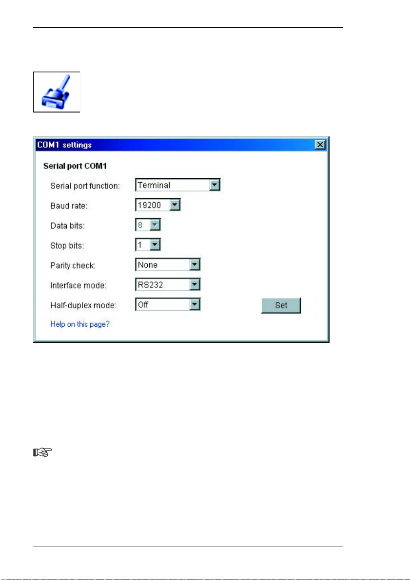
COM1 interface parameters
The RS232/485 serial interface port can be configured to meet your
requirements.
Serial port function:
Select a controllable device from the list. If you want to use the serial interface to
transmit transparent data, select Transparent.
Note
After selecting a device, the remaining parameters in the window are set
automatically and should not be changed.
Baud rate:
Select the value for the data transmission rate in Bit/s.
40 VideoJet 8000
Page 41

Chapter 5 Configuration using a Web Browser
Data bits:
The number of data bits per character cannot be changed.
Stop bits:
Select the number of stop bits per character.
Parity:
Select the type of parity check.
Interface mode:
Select the desired protocol for the serial interface.
Half-duplex mode:
Choose the setting appropriate for your application.
VideoJet 8000 41
Page 42
Configuration using a Web Browser Chapter 5
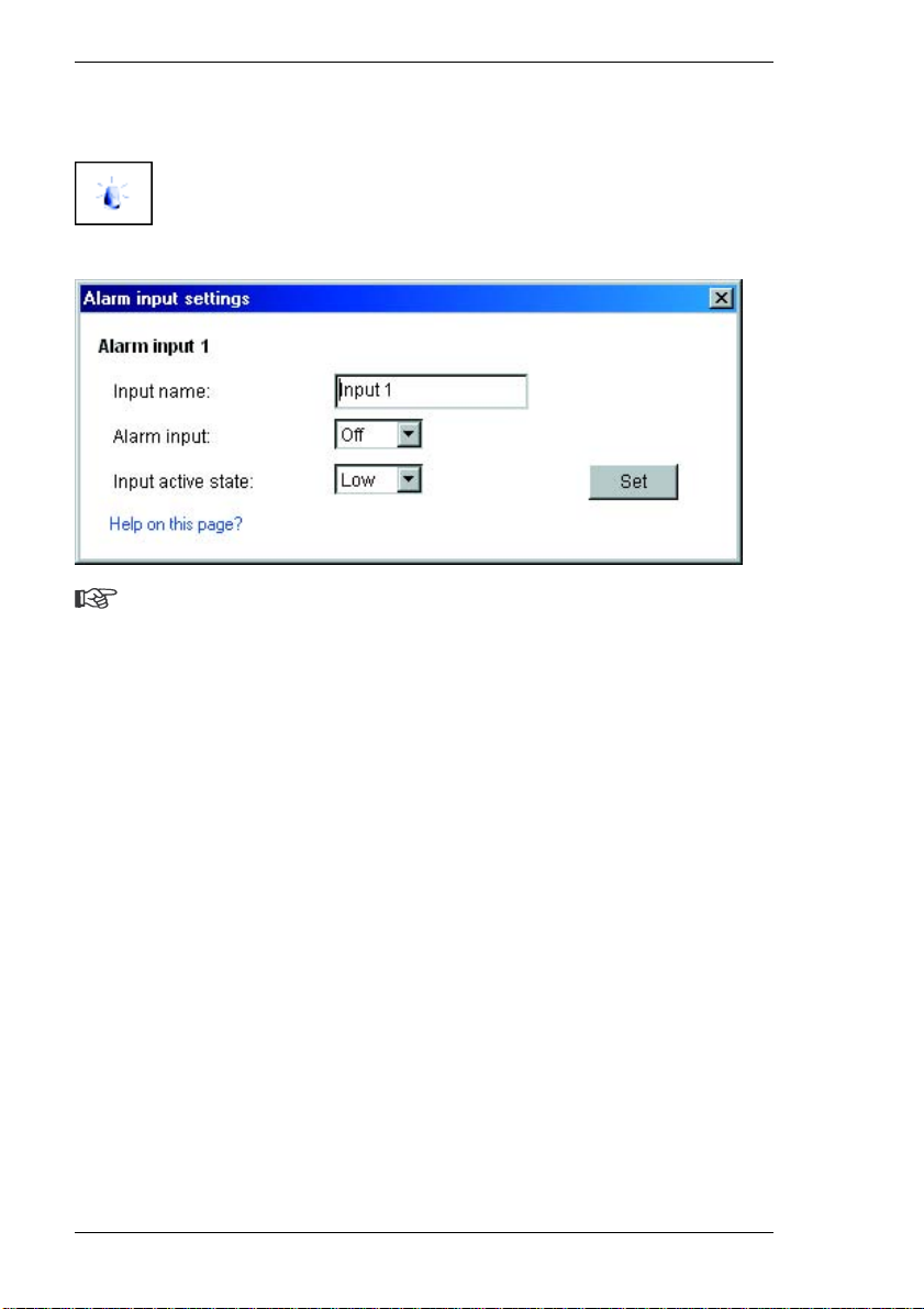
Alarm input settings
Note
The settings for the alarm inputs must be configured separately for each
input. To do this, click the alarm icons in turn. The configuration page is
identical for all the inputs.
Alarm input name:
You can enter a name for each alarm input, which is then displayed next to the
icon for the alarm input on the video live page during the respective configuration
(see page 106).
Alarm input active:
Select the option On in order to activate the alarm via the corresponding external
alarm sensor. Otherwise, select Off.
Alarm input status:
You can choose whether the alarm is triggered by an Active high or Active low
voltage level.
42 VideoJet 8000
Page 43
Chapter 5 Configuration using a Web Browser
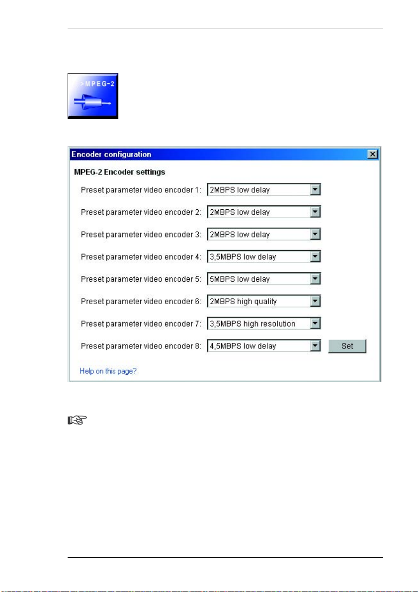
MPEG-2 encoder configuration
Parameter values for the encoders:
Note
The settings for the encoders must be configured separate ly for each
camera input. The numbering of the encoders corresponds to the labeling
of the inputs on the back of the unit.
The MPEG-2 data transmission can be configured to suit the environment (for
instance, network architecture, bandwidth, etc.).
Preconfigured profiles are provided, which re flect different priorities and
environments.
VideoJet 8000 43
Page 44

Configuration using a Web Browser Chapter 5
] 2MBPS low delay
2 MBit/s transmission rate with a low delay for image refresh
] 3.5MBPS low delay
3.5 MBit/s transmission rate with a low delay for image refresh
] 5MBPS low delay
5 MBit/s transmission rate with a low delay for image refresh
] 2MBPS high quality
2 MBit/s transmission rate with high image quality
] 3.5MBPS high quality
3.5 MBit/s transmission rate with high image quality
] 5MBPS high quality
5 MBit/s transmission rate with high image quality
] 3MBPS low delay
3 MBit/s transmission rate with a low delay for image refresh
] 4.5MBPS low delay
4.5 MBit/s transmission rate with a low delay for image refresh
– Select the desired setting from the list.
44 VideoJet 8000
Page 45
Chapter 5 Configuration using a Web Browser
Alarm connections
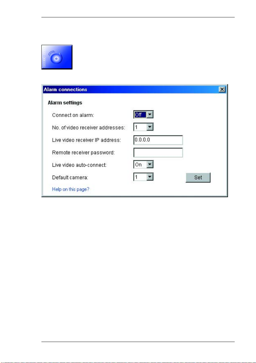
You can select a number of options for the response of the VideoJet 8000 to an
alarm. In case of an alarm, the VideoJet 8000 can establish a connection to a
predefined IP address (VCS hardware receiver or PC with receiver software)
automatically. You can enter up to 10 IP addresses which will be selected in
sequence by the unit until a connection is established. You can also choose
which camera image should be automatically be displayed first on the receiver in
the case of an alarm.
Connect on alarm:
Select On so that the VideoJet 8000 establishes a connection automatically to
one of the pre-defined IP addresses in the event of an alarm.
Number of the alarm IP address:
Here you assign the numbering for the IP addresses to be contacted in the event
of an alarm. The unit contacts the remote locations on e after the other in the
numbered sequence until a connection has been established.
VideoJet 8000 45
Page 46

Configuration using a Web Browser Chapter 5
Video receiver IP address:
For each number, enter the corresponding IP address of the desired receiver.
Remote receiver password:
If necessary, enter the password, if the remote location is protected by a
password.
Live video auto-connect:
Select the option On if an active connection should be automatically
reestablished to one of the previously specified IP addresses after each restart,
e.g. after a connection breakdown or network dropout.
Select camera on alarm:
Here you can select the camera whose image will automatically be displayed first
to the receiver after the alarm connection has been established. Depending on
the system configuration, the receiver can then also select the other cameras.
46 VideoJet 8000
Page 47
Chapter 5 Configuration using a Web Browser
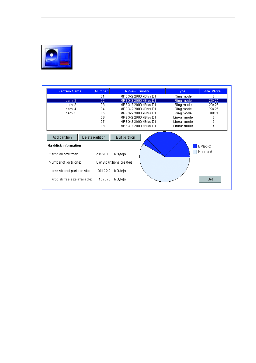
Partition
The VideoJet 8000 hard drive can have up to eight partitions configured in the
same way as is typical for computer hard drives. Parameters can be defined
individually for each partition, such as size, quality, type of video recording and
the compression standard used. Changes in these parameters result in a
complete reorganization, causing saved data on the partition to be deleted.
The VideoJet 8000 requires a dedicated partition for the recordings of each
camera connected. Each partition is linked to its own encoder or camera input:
camera input Video 1 with partition 01, camera input Video 2 with partition 02 etc.
The assignments cannot be changed. Therefore all partitions are always shown
in the list, regardless of whether a configuration is present or has been deleted.
It is necessary to configure all eight partitions to record with eight cameras. The
default configuration already has eight partitions configured.
All the partitions are listed in the table on the Partition page by name, sequential
number, recording format/video quality, recording type and partition size.
VideoJet 8000 47
Page 48
Configuration using a Web Browser Chapter 5
This page also provides an overview of the hard drive information, such as total
size, number of partitions, space used on the partitions and the number of
unallocated megabytes of space.
A pie chart shows how much space is reserved for recordings or is unused.
General procedure
Warning!
Changes to the size or number of partitions will result in reorganization of
the entire hard drive and the loss of all saved data. Therefore, before
making changes to the parameters mentioned, check the recordings and
back up the important sequences to your computer's hard drive.
Note
If there are already eight partitions configured, the Installation Wizard can
only be started after at least one partition has been deleted.
When the Installation Wizard has started, a new information window will appear
in which settings can be config ured.
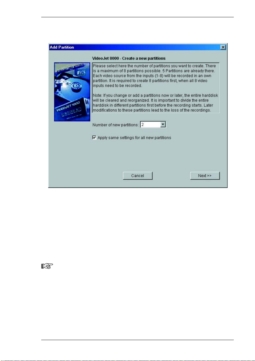
The entire wizard sequence must be completed once for each hard drive partition
created. For this reason, the number of partitions to be created can be selected
immediately after starting the Installation Wizard. The wizard will then restart
automatically until all the partitions specified are configured.
Note
More than one partition with the same configuration can be created in a
single process. Mark the checkbox Apply same settings for all new
partitions on the initial page of the wizard.
48 VideoJet 8000
Page 49
Chapter 5 Configuration using a Web Browser
– Click Add partition to start the wizard for partitions.
– Always read the information in the upper part of the window first.
– Click in the text fields to enter values or use the other controls available, such
as buttons, check boxes or list fields.
– Click Next >> to continue to the next step.
– Click << Back to look at the previous step again.
Applying the settings
Note
Continue with the Installation Wizard until the last page. Only there is it
possible to save the settings by clicking Finish.
Settings made with the Installation Wizard only take effect after the Finish button
on the last page is clicked.
Clicking Cancel causes the original settings to remain unchanged.
VideoJet 8000 49
Page 50

Configuration using a Web Browser Chapter 5
– After closing the Installation Wizard, click the Set button in the main window to
send the changes to the unit and save them there.
Changing partition data
The configuration of the partitions can be changed at any time .
Warning!
Changes to a partition that affect the name, video quality, recording format
or type or the number of alarms and the pre- and post-alarm recording times
cause the partition to be reorganized and all saved data on that partition to
be lost. Therefore you should back up all the important sequences to your
computer's hard drive. If the total recording time or the size of the partition
is changed, the entire configuration of the hard drive is lost.
The desired changes can be made in the Partition Settings window.
– Click to select the partition in the list that you want to change.
– Click Edit partition. The Partition Settings window will appear, showing the
information for the selected partition.
– Make the desired changes.
– Click Set to save the changes.
– After closing the window, click the Set button in the main window to send the
changes to the unit and save them there.
50 VideoJet 8000
Page 51

Chapter 5 Configuration using a Web Browser
Deleting partitions
A partition can be deleted at any time.
Warning!
Deleting a partition causes the entire hard drive to be reorganized and all
sequences stored on it to be lost. Therefore, before deleting partitions,
check the recordings and back up the important sequences to your
computer's hard drive.
– Click a partition in the list to select it.
– Click Delete partition to delete the selected partition. The partition will not be
removed from the list. Rather, it remains without a name or size specification
in order to give you a better overview.
– Click Set to send the changes to the unit and save them.
VideoJet 8000 51
Page 52
Configuration using a Web Browser Chapter 5
Recorder
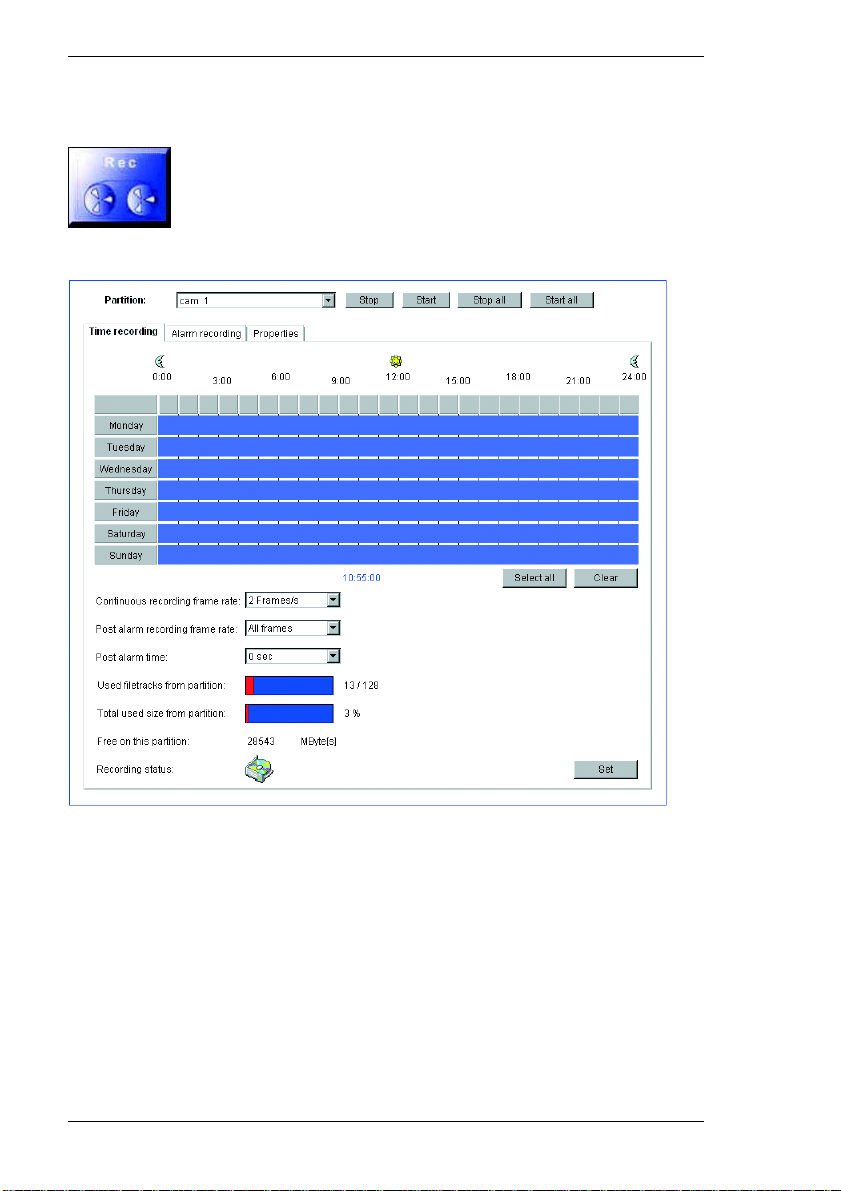
Here you set the parameters for recording on the local hard drive. Recording may
be done continuously or only in the event of an alarm.
Partition:
Select the partition on which you want to record. Recording of the individual
camera inputs is always done on dedicated partitions.
Timed recording
Here you can specify the times during which continuous recording on the hard
drive takes place.
52 VideoJet 8000
Page 53

Chapter 5 Configuration using a Web Browser
For each weekday, there are separate selection fields for each partition and thus
for each camera input. You can select 16 individual recording periods for each
weekday.
Note
If a period has already been selected for the alarm record ing, you cannot
select this period for the timed recording (see Alarm recording, page 55).
– Left-click on the weekday on which the recording should start and hold down
the mouse button.
– Now drag the selected field to the desired ending time for the recording and
release the mouse.
– Right-click a selected time segment to delete it.
– Click Select all to select all time segments.
– Click Delete all to delete all selected periods.
Continuous recording frame rate:
You can select the frame rate for default recordings. Default recordings are those
that are not triggered by an alarm. The option All frames is used to record at
25 fps (PAL) or 30 fps (NTSC) from a camera to its assigned partition. Other
settings result in a lower frame rate and thus require less partition space. This
means that the VideoJet 8000 can record for a longer period of time.
Post-alarm recording frame rate:
If an alarm occurs during a default recording, the frame rate can be changed
automatically to the post-alarm rate. The option All frames is used to record at
25 fps (PAL) or 30 fps (NTSC) from a camera to its assigned partition. Other
settings result in a lower frame rate.
Post-alarm time:
Select the period after an alarm during which recording should continue at a
different frame rate.
Used file tracks from partition:
Up to 128 recording tracks are created automatically on a partition. Each new
recording takes place on a separate track.
VideoJet 8000 53
Page 54

Configuration using a Web Browser Chapter 5
Selecting the option Linear mode means that no more new recordings are made
after the 128 tracks have been used. Old recordings must be deleted before the
tracks can be re-used. Selecting Ring mode means that the 129th recording will
be written on the first track, so that the oldest recording is always overwritten by
the newest.
Total used size from partition:
The display indicates the space currently used on the partition.
Free on this partition:
The display indicates the current amount of free space on the partition.
Recording status:
The icon indicates the recording status on this partition. When a recording is
being made, the icon is animated.
54 VideoJet 8000
Page 55
Chapter 5 Configuration using a Web Browser
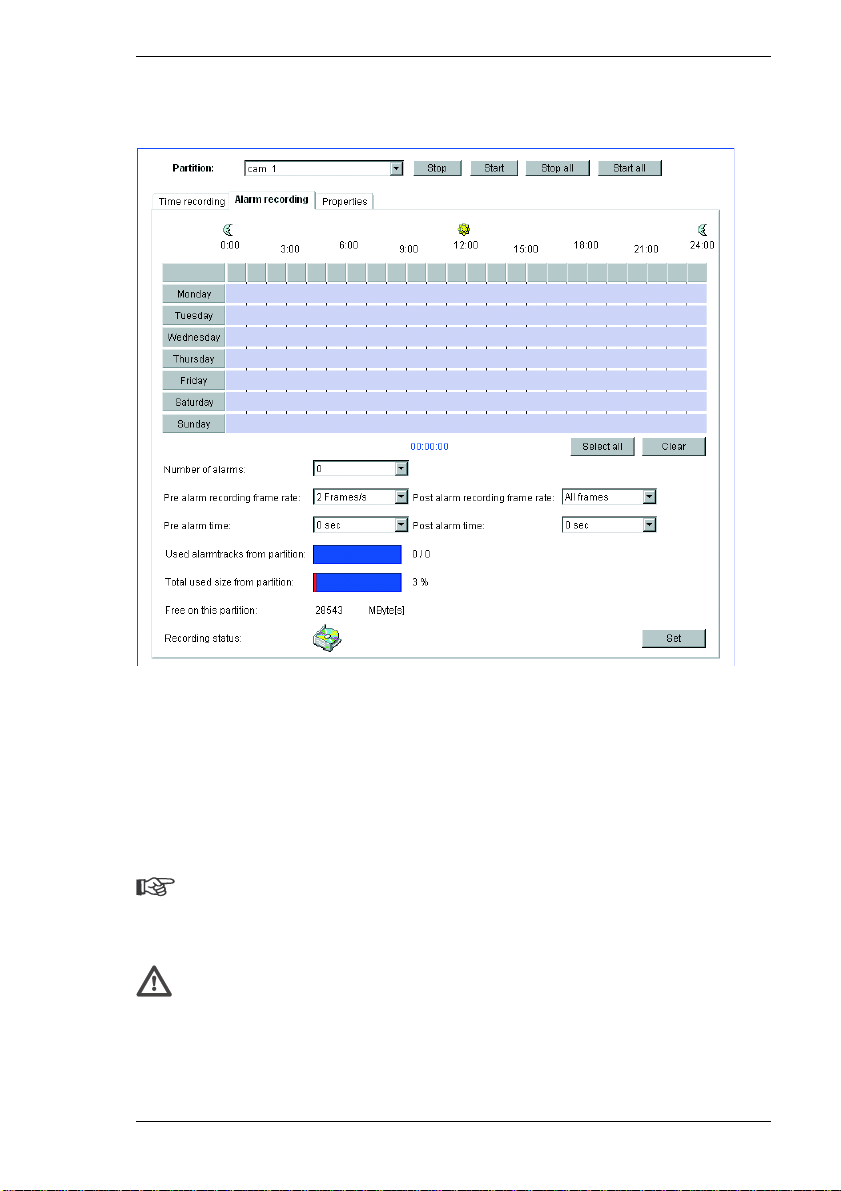
Alarm recording
Here you can define the times when recordings are to be made by the selected
camera on the hard drive in the event of an alarm. When recorded sequences are
played back, the time of the alarm activation is specially marked so that it can be
easily identified.
Just like for timed recording, you can select 16 separate time periods on each
weekday for alarm recording. An alarm recording takes place only during the
selected periods.
Note
If a time period has already been selected for the timed recording, you can
no longer select it for alarm recording (see Timed recording, page 52).
Warning!
For alarm recordings, alarm tracks must be set up on the desired partition
(see Number of alarm tracks, page 56).
VideoJet 8000 55
Page 56

Configuration using a Web Browser Chapter 5
The VideoJet 8000 uses a special recording mode for alarm recording to optimize
the use of storage capacity. As soon as a time slot begins for the alarm recording,
continuous recording starts on a segment the size of a complete alarm sequence
(pre- and post-alarm). This segment on the partition works like a ring buffer and
is overwritten again and again until an alarm is actually triggered. After that,
recording on this segment will go on for the time predefined for post-alarm
recording, and then a new segment will be used in the same way. For this reason
the recorded alarm file is always saved in its full length to the partition and the
recording space required for each alarm recording can be calculated easily.
Note
When the time slots for default and alarm recording overlap, the default
recording has priority.
Number of alarm tracks:
Here you set the number of alarm tracks on the partition. One alarm event can be
recorded on each alarm track. The specified number of alarms can be recorded
and archived accordingly. A partition can contain a maximum of 128 alarm
recordings. If the option Ring mode is set for the partition, the predefined number
of the latest alarm recordings will be stored. If the option Linear mode is set,
recording will stop as soon as all the alarm tracks have been written.
Pre-alarm recording frame rate:
You can select the frame rate for pre-alarm recording. The option All frames is
used to record at 25 fps (PAL) or 30 fps (NTSC) from a camera to its assigned
partition. Other settings result in a lower frame rate.
Post-alarm recording frame rate:
You can select the frame rate for alarm recording. The option All frames is used
to record at 25 fps (PAL) or 30 fps (NTSC) from a camera to its assigned partition.
Other settings result in a lower frame rate.
Pre-alarm time:
Select the period to be covered by the pre-alarm recording.
Post-alarm time:
Select the duration of the alarm recording.
56 VideoJet 8000
Page 57

Chapter 5 Configuration using a Web Browser
Used alarm tracks from partition:
The display indicates how many of the alarm tracks are already used.
Total used size from partition:
The display indicates the space currently used on the partition.
Free on this partition:
The display indicates the current amount of free space on the partition.
Recording status:
The icon indicates the recording status on this partition. When a recording is
being made, the icon is animated.
VideoJet 8000 57
Page 58
Configuration using a Web Browser Chapter 5
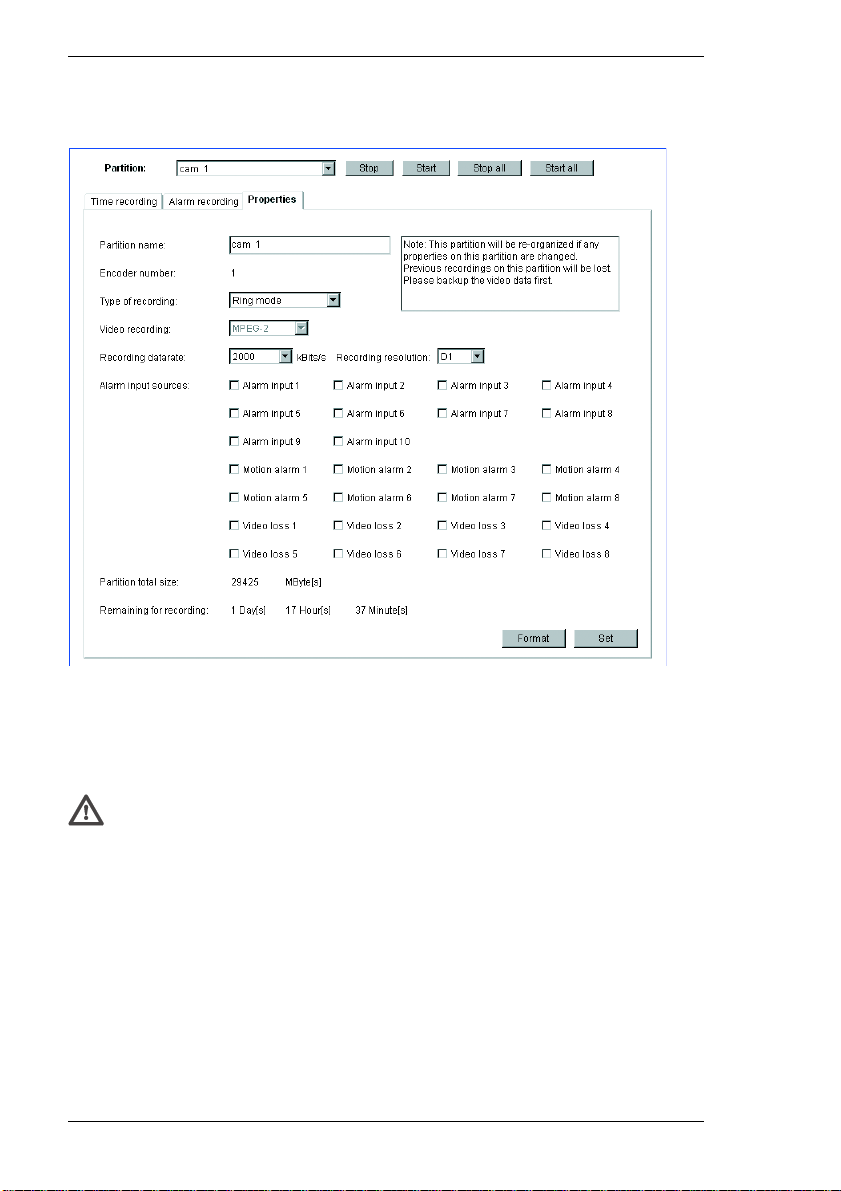
Settings
You can view the current parameters for each selected partition and change them
as required in the recording scheduler. At the same time, you can activate the
various alarms which must be taken into account during the recording. You can
also set the data rate for the recording here.
Warning!
Changes to a partition that affect the name, video quality, recording format
or type or the number of alarms and the pre- and post-alarm recording times
cause the partition to be reorganized and all saved data on that partition to
be lost. You should therefore back up all important sequences to the hard
drive of the computer before making such changes.
Partition name:
Here you can enter a new name for the partition if needed.
58 VideoJet 8000
Page 59

Chapter 5 Configuration using a Web Browser
Encoder number:
This shows information about the number of the associated encoder. The number
corresponds to the respective camera input on the back of the unit.
Type of recording:
You can change the recording mode as required. In Ring mode recording will
continue indefinitely. When the maximum hard drive space has been reached,
the oldest recordings will be overwritten automatically. In Linear mode, recording
will continue until all the drive space has been used. Then recording will stop.
Recording data rate:
Select the desired recording rate here. The image quality increases automatically
as the data rate increases. However, a higher data rate reduces the recording
duration on the partition.
The maximum remaining recording time is recalculated after the data rate has
been set and is displayed further down the page (Remaining for recording).
Recording resolution:
Here you can change the image resolution for the recording as required.
Alarm input sources:
Here you can select the alarm sensors that should trigger an alarm. Select the
checkboxes of the alarm sources so the corresponding alarm sensors will be
monitored for alarm recording.
Note
A motion or video alarm from one camera can be used to trigger alarm
recording by another camera. The motion alarm must be configured on the
Motion Detector page (see page 98). Alarm settings are activated on the
Alarm input settings page (see page 42). The video alarm is activated on
the Camera settings page (see page 36).
Partition total size:
The displayed value shows the total space in MB occupied by the partition on the
hard drive.
VideoJet 8000 59
Page 60

Configuration using a Web Browser Chapter 5
Remaining for recording:
Here the maximum time remaining for recording is displayed. It is automatically
updated after the parameters are changed.
Deleting partitions
Partitions can be deleted at any time.
Warning!
Deleting a partition causes the entire hard drive to be reorganized and all
sequences stored on it to be lost. Therefore, before deleting partitions,
check the recordings and back up the important sequences to your
computer's hard drive.
– Click Format to delete the partition currently shown.
Activating partitions
After configuring a partition, it can be activated by clicking the Start button and
thereby starting recording activities.
After the partition is activated the entire field for it will be shown as gray. The icon
at the bottom of the page indicates the recording status on the partition. When a
recording is being made, the icon is animated.
Recording activities can be stopped at any time, and one, several or all partitions
can be deactivated.
– Click Start to activate the currently selected partition and begin recording
activities for it.
– Click Start all to activate all the configured partitions and begin the associated
recording activities.
– Click Stop to deactivate the currently selected partition and terminate its
recording activities.
– Click Stop all to deactivate all the configured partitions and halt the associated
recording activities.
60 VideoJet 8000
Page 61
Chapter 5 Configuration using a Web Browser
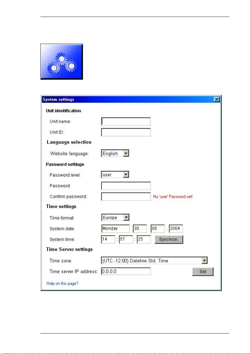
System settings
Various basic configuration data for the VideoJet 8000 can be set or selected
here.
VideoJet 8000 61
Page 62

Configuration using a Web Browser Chapter 5
Unit name:
The unit can be assigned a name to assist in identifying it. This name will be
overlaid on the video image, depending on the configuration. Furthermore, device
names simplify the administration of multiple units in larger systems using
programs such as VIDOS from VCS.
Note
The unit name is used to identify a unit remotely, such as in the case of an
alarm call. Enter a designation that makes it as easy as possible to identify
the location unambiguously.
Unit ID:
Each VideoJet 8000 should be assigned a unique identifier that can be entered
here as an additional means of identification.
Web site language:
Here you select the language of the user interface.
user name:
A VideoJet 8000 unit is generally protected by a password to prevent
unauthorized access. The VideoJet 8000 uses three levels of authorization: live,
service and user.
The service authorization level allows you to use all the functions of the
VideoJet 8000 and change all the settings after entering the proper password.
The user authorization level allows you to operate the unit and control cameras
but not to change the configuration.
Live authorization allows you to view live images but neither change the
configuration nor control cameras or other peripheral devices.
Password:
You can define and change passwords for each authorization level if the unit is
not password protected or if logged on with service authorization. Only one
password at a time can be changed. To change the password of another
authorization level, this configuration page must be reloaded.
Confirm password:
Re-enter the new password to avoid typing errors.
62 VideoJet 8000
Page 63

Chapter 5 Configuration using a Web Browser
Time format
The desired date format for the display can be selected:
] Europe: DD.MM.YYYY
] USA: MM/DD/YYYY
] Japan: YYYY/MM/DD
System date and time:
If there are a number of units operating in your system or network, it is important
to synchronize their internal clocks. Only if all units operate with the same time it
is possible, for example, to make correct identification and evaluation of
recordings occurring at the same time.
– Enter the current date. It is not necessary to enter the day of week; this is
supplied automatically by the internal clock
– Enter the current time or click the Synchron. button to copy the system time
from your computer to the VideoJet 8000.
Time zone and Time server IP address:
The VideoJet 8000 can receive a time signal from a TIME server (NTP server)
and use it to set the internal clock. The unit calls up the time signal automatically
every two hours.
– Select the time zone where the system is located from the list.
– Enter the IP address of the desired NTP server.
VideoJet 8000 63
Page 64
Configuration using a Web Browser Chapter 5
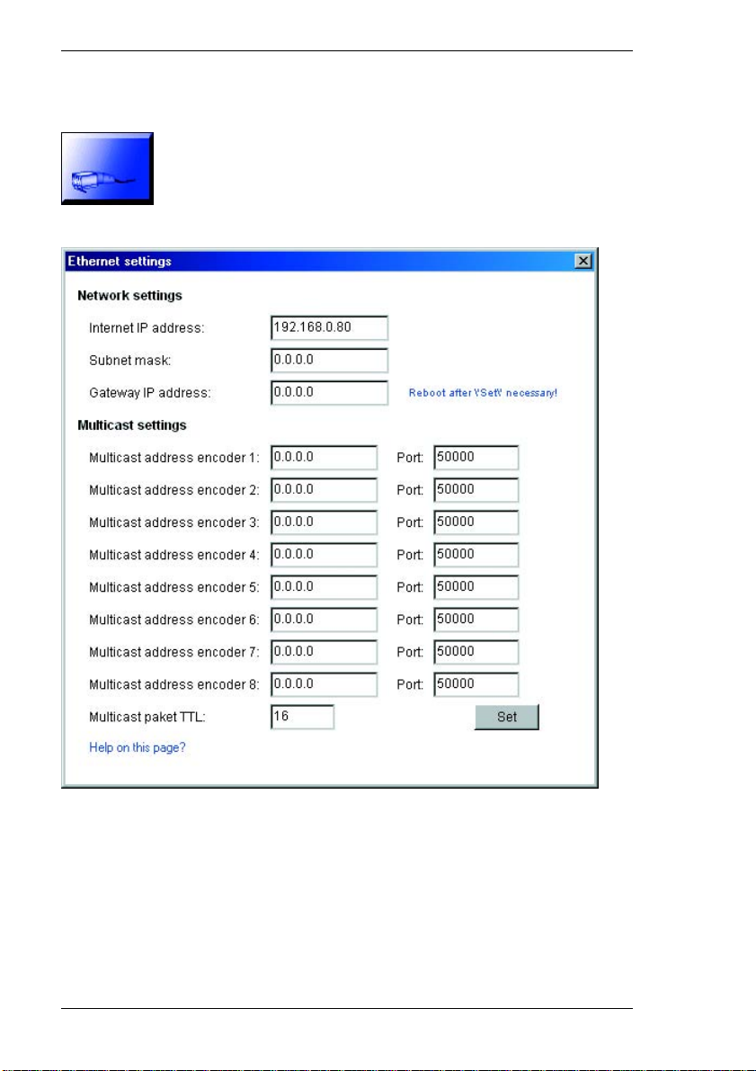
Ethernet settings
The settings in this dialog are used to integrate the unit into an existing network.
The group IP address (multicast address) and the channel (port) must be set
separately for each encoder.
64 VideoJet 8000
Page 65
Chapter 5 Configuration using a Web Browser
Warning!
Changes to the IP address, subnet mask or gateway address are sent to
the unit when the Set button is clicked. However, they only take effect after
the unit is restarted!
– Click Set after entering a new IP address.
– To do this, enter the old IP address in the address field of the Web browser
and append /reset to it (e.g. 192.168.0.80/reset). The VideoJet 8000
will be restarted after which it can only be accessed at the new IP address.
Internet IP address:
Enter the desired IP address for the VideoJet 8000 in this field. The IP address
must be valid for the network.
Subnet mask:
Enter the subnet mask here if the unit is to communicate via a subnet.
Gateway IP address:
Enter the corresponding IP address here if the unit is to establish a connection
independently outside the local network. Otherwise, this field can remain empty
(0.0.0.0).
Note
If a switch is used additional settings must be configure d in expert mode
(see page 103).
Multicast configuration
In addition to a 1:1 connection between an encoder and a single receiver
(unicast), the VideoJet 8000 can enable multiple receivers to receive the video
signal from an encoder simultaneously. This is achieved either by duplicating the
data stream in the unit with subsequent distribution to multiple receivers (multiunicast) or by distribution of a single data stream over the network to a number
of receivers in a defined group (multicast). A dedicated multicast address and
port can be specified for each of the eight encoders.
Note
The prerequisite for multicast operation is a multicast-capable network
using the UDP and IGMP protocols. Other group membership protocols are
not supported. The TCP protocol does not support multicast connections.
VideoJet 8000 65
Page 66

Configuration using a Web Browser Chapter 5
The MPEG-2 data transfer protocol is designed for at most one multi-unicast
connection to each encoder. The transparent data connection is maintained by
the first unit. However after about 15 seconds of inactivity, the data connection is
automatically terminated and another unit can exchange transparent data with
the transmitter.
For multilink operation, the network need not be multicast-capable, because the
VideoJet 8000 is also multi-unicast compatible. Duplication of the data on the unit
requires considerable processor power and, under certain circumstances, leads
to limitations in the picture quality.
When the multicast address is set to 0.0.0.0, the VideoJet 8000 operates in multiunicast mode (copies the data streams on the unit).
If a valid multicast group IP address is entered for each encoder, the unit operates
in the multicast mode (duplication of the data stream on the network).
Multicast address encoder 1 ... Multicast address encoder 8:
A special IP address (class D address) must be configured for multicast operation
in a multicast-enabled network.
The network must support group IP addresses and the Internet Group
Management Protocol (IGMP). The address space is from 224.0.1.0 to
238.255.255.255.
The multicast address can be the same for multiple encoders. Then however it is
necessary to use a different port in each case so that multiple data streams are
not sent simultaneously over the same port and multicast address.
66 VideoJet 8000
Page 67

Chapter 5 Configuration using a Web Browser
Port:
In the case of simultaneous data streams in MPEG-2 format the data streams
must be assigned to different ports.
Enter the port address for the particular encoder here.
Multicast packet TTL:
A value can be entered to specify how long the multicast data packets are active
on the network. If multicast is to be run over a router the value must be greater
than 1.
VideoJet 8000 67
Page 68
Configuration using a Web Browser Chapter 5
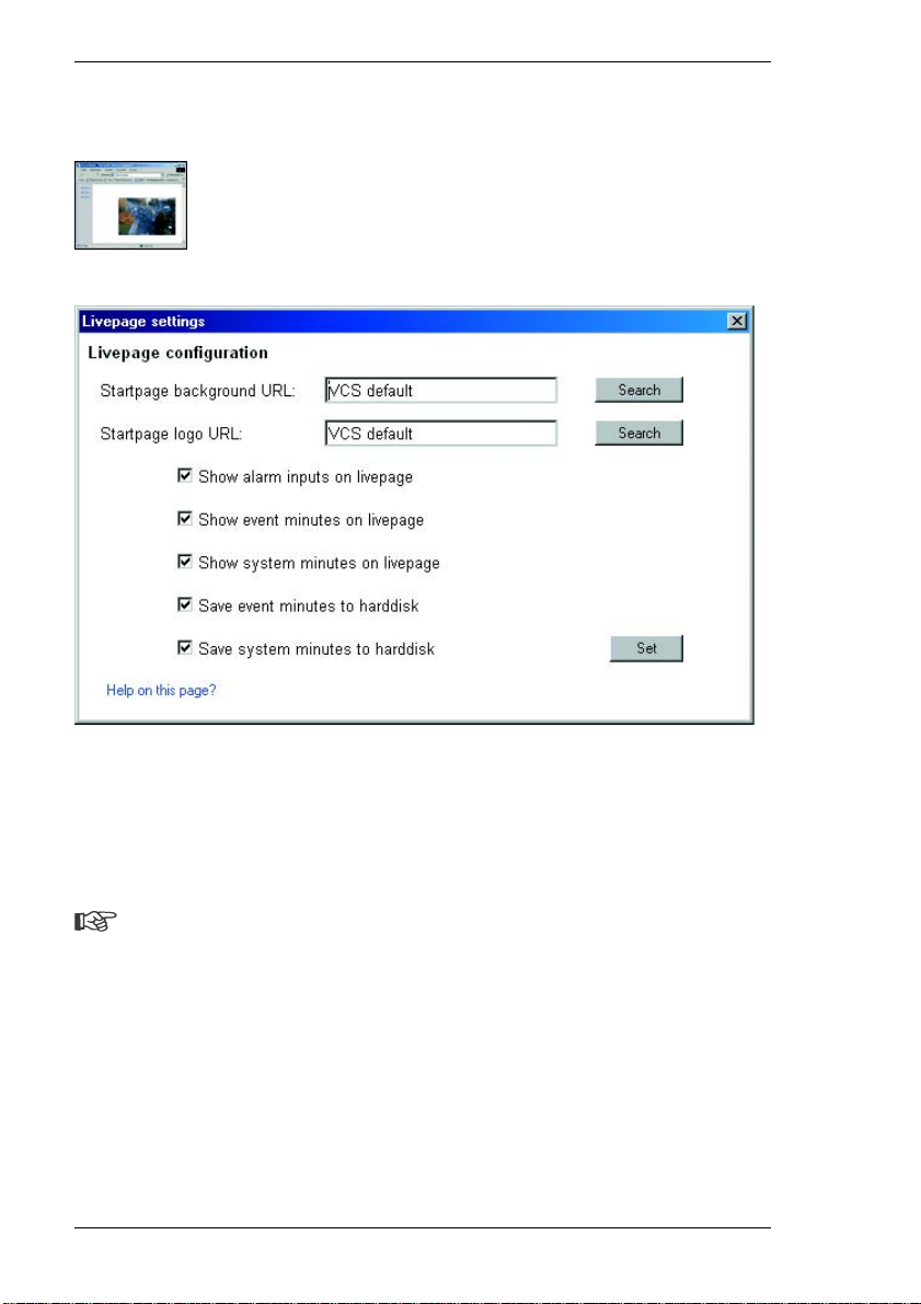
Livepage settings
In this dialog, the appearance of the Livepage can be set up to suit your
requirements. Options are provided here to display various information and
operating elements in addition to the video image.
Moreover, individual background graphics can be used for the main window and
the upper area of the window (banners).
Note
Either GIF or JPEG images can be used. The file paths must correspond to
the access mode (local paths such as C:\Images\Logo.gif for local files and
URLs such as http://www.vcs.com/images/logo.gif for files on the Internet).
Please note for access via Internet/intranet that there must be a connection
in order to display the image. The image files are not stored on the
VideoJet 8000.
– Mark the checkboxes for the information to be displayed on the Livepage. The
selected elements are checkmarked.
68 VideoJet 8000
Page 69

Chapter 5 Configuration using a Web Browser
– Check the display of the desired information on the Livepage.
Startpage background URL:
Enter the path to a suitable background graphic in this field. The image can be
stored on a local computer, a local network or at an Internet address.
Click Search if necessary to find a suitable image on the local network.
Startpage logo URL:
Enter here the path for a suitable image for the upper part of the window (banner).
The image can be stored on a local computer, a local network or at an Internet
address.
– Click Search if necessary to find a suitable image on the local network.
Note
To restore the original graphics, just delete the entries in the fields
Startpage background URL and Startpage logo URL.
Show alarm inputs on livepage
Alarm inputs are displayed next to the video image as icons along with their
assigned names. If an alarm is active the corresponding icon changes color.
Show event minutes on livepage
The event log will be displayed with date and time in a field under the video
image.
Show system minutes on livepage
The system log will be displayed with date and time in a field under the video
image and provide information about connections, etc.
Save event minutes to hard disk
Select this option to save the event log in a text file on the local computer.
These logs can be viewed, edited and printed with any software that can work
with text files (such as Microsoft Word or Excel).
VideoJet 8000 69
Page 70

Configuration using a Web Browser Chapter 5
Save system minutes to hard disk
Select this option to save the system log in a text file on the local computer.
These logs can be viewed, edited and printed with any software that can work
with text files (such as Microsoft Word or Excel).
Note
If the saving of log files is enabled (for example "Save event minutes on
livepage"), these will be stored by default as text files on the Windows
Desktop. The path for saving the files can be changed in expert mode (see
page 108).
70 VideoJet 8000
Page 71
Chapter 5 Configuration using a Web Browser
Expert Mode
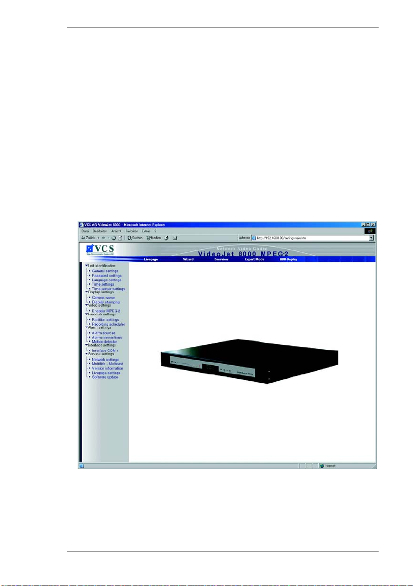
Expert Mode allows all parameters of the VideoJet 8000 to be configured. You
can view the current settings by opening one of the configuration pages. The
settings can be changed by entering new values or by selecting a predefined
value from a list field.
Navigation
You can switch to expert mode after clicking the Settings link on the Livepage.
– Click the Expert Mode link. The initial page will be opene d.
– Click one of the links on the left edge of the window. The corresponding page
will be opened.
Applying changes
Each configuration page shows the current settings. The settings can be changed
by entering new values or by selecting a predefined value from a list field.
VideoJet 8000 71
Page 72
Configuration using a Web Browser Chapter 5
– Click Set after each change to save it.
Warning!
Save each change with the associated Set button. When Set is clicked,
only the changes in the relevant (blue-bordered) field are saved. Changes
in any other fields are ignored.
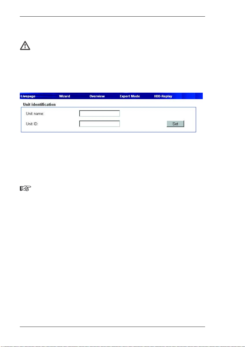
Unit identification
Unit name:
The unit can be assigned a name to assist in identifying it. This name will be
overlaid on the video image, depending on the configuration. Furthermore, device
names simplify the administration of multiple units in larger systems using
programs such as VIDOS from VCS.
Note
The unit name is used to identify a unit remotely, in case of an alarm for
example. Enter a designation that makes it as easy as possible to identify
the location unambiguously.
Unit ID:
Each VideoJet 8000 should be assigned a unique identifier that can be entered
here as an additional means of identification.
72 VideoJet 8000
Page 73
Chapter 5 Configuration using a Web Browser
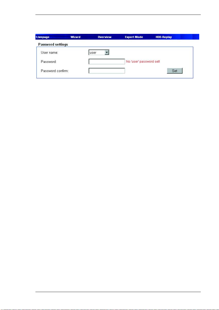
Password settings
User name:
A VideoJet 8000 unit is generally protected by a password to prevent
unauthorized access. The VideoJet 8000 uses three levels of authorization: live,
service and user.
The service authorization level allows you to use all the functions of the
VideoJet 8000 and change all the settings after entering the proper password.
The user authorization level allows you to operate the unit and control cameras
but not to change the configuration.
Live authorization allows you to view live images but you can neither change the
configuration nor control cameras or other peripheral devices.
Password:
You can define and change passwords for each authorization level if the unit is
not password protected or if logged on with service authorization. Only one
password at a time can be changed. To change the password of another
authorization level, this configuration page must be reloaded.
Confirm password:
Re-enter the new password to avoid typing errors.
VideoJet 8000 73
Page 74
Configuration using a Web Browser Chapter 5
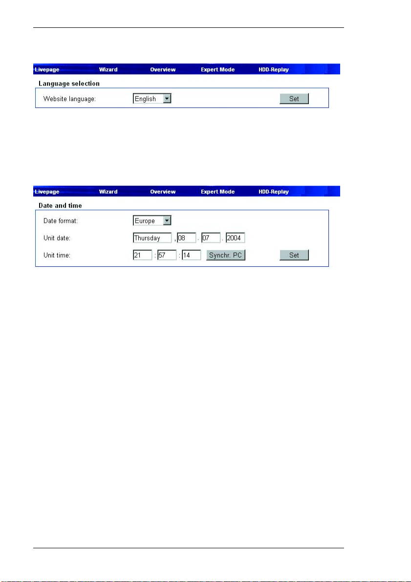
Language selection
Web site language:
Here you select the language of the user interface.
Date and time
If a number of VideoJet units are part of a system, it is important that the internal
clocks of these separate units be synchronized. Only if all units operate with the
same time it is possible, for example, to make correct identification and
evaluation of recordings occurring at the same time.
Date format:
The desired date format for the display can be selected:
] Europe: DD.MM.YYYY
] USA: MM/DD/YYYY
] Japan: YYYY/MM/DD
Unit date:
Enter the current date here. It is not necessary to enter the day of week; this is
supplied automatically by the internal clock
Unit time:
Enter the current time here or click the Synchr. PC button to copy the system
time from your computer to the VideoJet 8000.
74 VideoJet 8000
Page 75
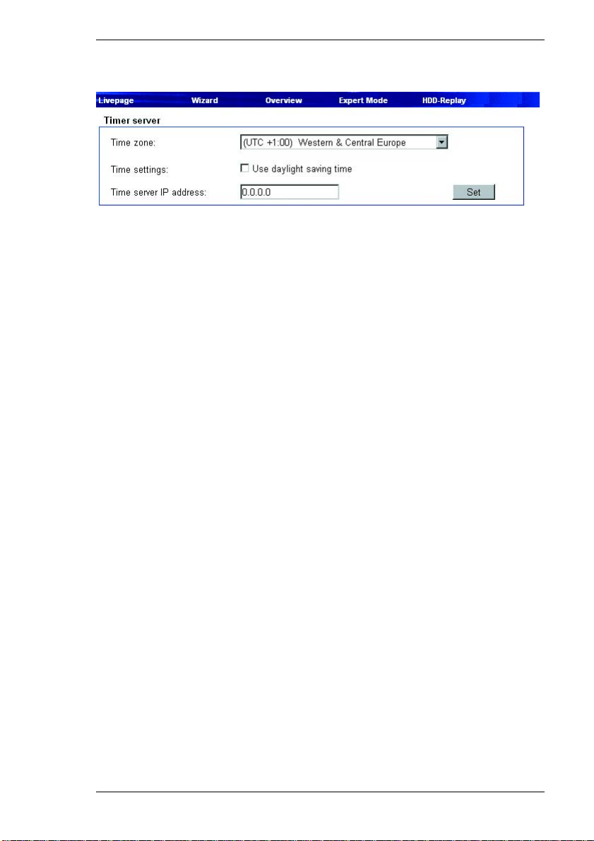
Chapter 5 Configuration using a Web Browser
Time server
The VideoJet 8000 can receive a time signal from a TIME server (NTP server)
and use it to set the internal clock. The device calls up the time signal
automatically every two hours.
Time zone:
Here you can select the time zone in which your system is located.
Time settings:
Select this during daylight savings time if the time change is to be taken into
account. Deselect it when standard time has resumed.
Time server IP address:
Enter the IP address of the desired NTP server if necessary.
VideoJet 8000 75
Page 76
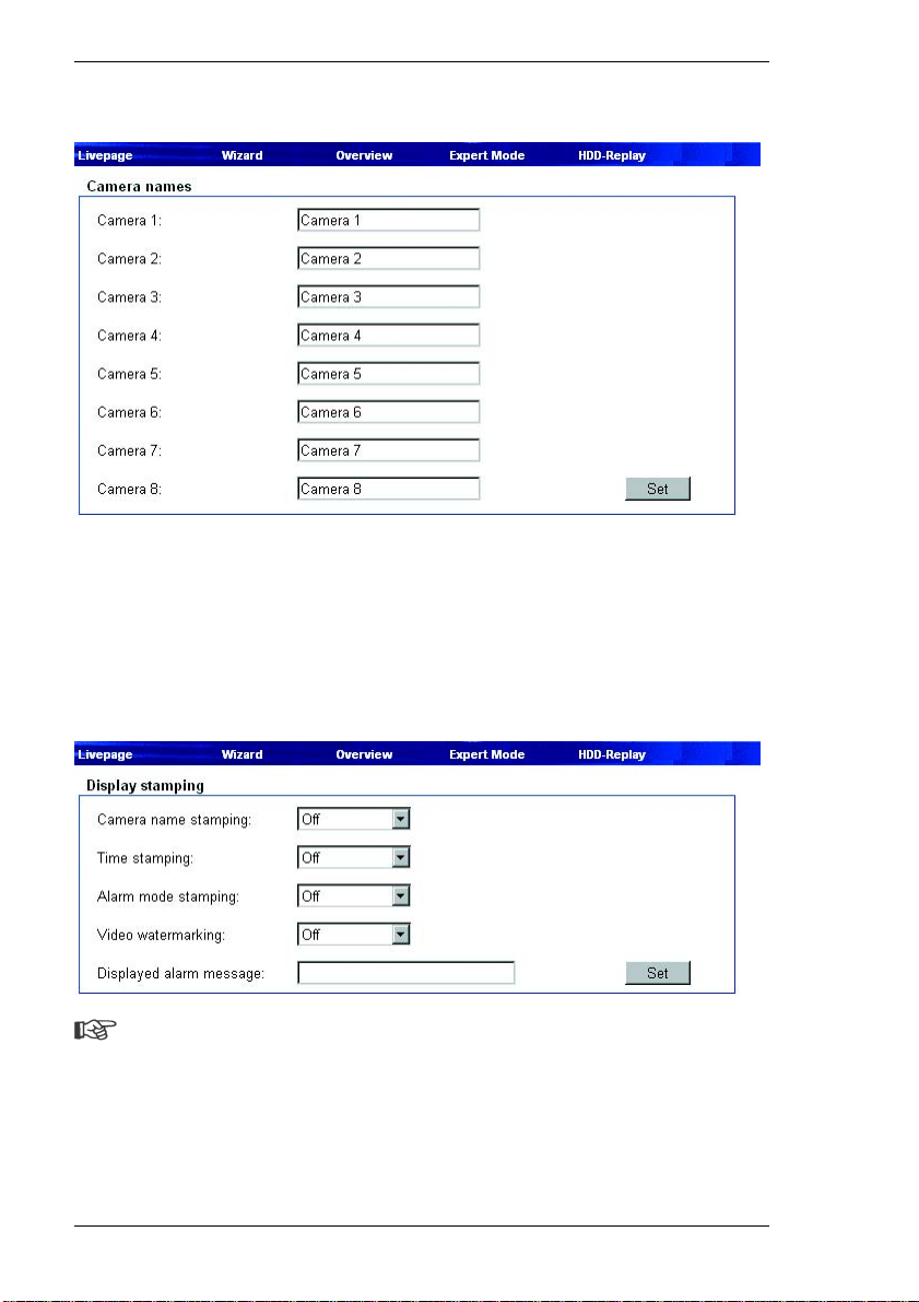
Configuration using a Web Browser Chapter 5
Camera names
Camera 1 ... Camera 8:
Enter the desired name for each camera here. The camera name makes it easier
to identify the remote camera location, in the event of an alarm for example. Enter
an unambiguous, understandable name in the field.
Display stamping
Note
The settings on this page apply to all camera inputs.
Camera name stamping:
This field sets the position of the camera name overlay. It can be displayed on
Top or on Bottom of the image or you can define a position yourself via the
76 VideoJet 8000
Page 77

Chapter 5 Configuration using a Web Browser
Hyperterminal and activate it choosing the option Custom. Or it can be set to Off
if no overlay of this information is to be shown.
Time stamping:
This field sets the position of the time and date overlay. It can be displayed on
Top or on Bottom of the image or you can define a position yourself via the
Hyperterminal and activate it choosing the option Custom. Or it can be set to Off
if no overlay of this information is to be shown.
Alarm mode stamping: Choose On if a text message should be overlaid in the event of an alarm.
Video watermarking:
Choose On if the video images transmitted are to be "watermarked". After
activation, all images will be marked with a green W. A red W indicates that the
sequence (live or saved) has been manipulated.
Displayed alarm message:
Enter the text to be shown in the event of an alarm. It can contain up to
31 characters.
VideoJet 8000 77
Page 78
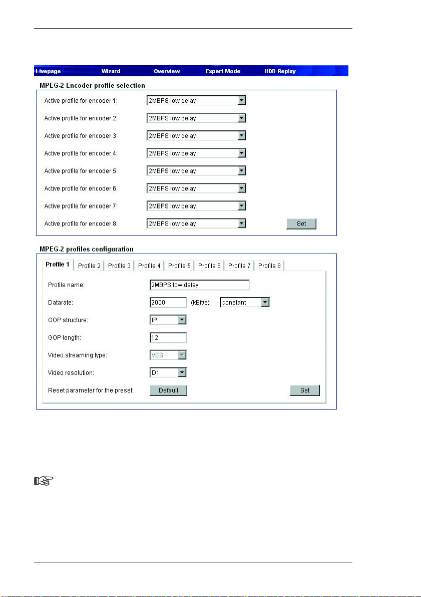
Configuration using a Web Browser Chapter 5
MPEG-2 encoder configuration
The data transmission parameters can be configured to fit the local operating
environment (network architecture, bandwidth, data structures, etc.). The
VideoJet 8000 has eight preconfigured profiles, which reflect different priorities
and environments.
Note
The settings for the encoders must be configured separately for each
camera input. The numbering of the encoders corresponds to the labeling
of the inputs on the back of the unit.
78 VideoJet 8000
Page 79

Chapter 5 Configuration using a Web Browser
MPEG-2 Encoder profile selection
Profiles can be selected here for each of the eight encoders.
Preconfigured profiles are provided, which re flect different priorities and
environments.
] 2MBPS low delay
2 MBit/s transmission rate with a low delay for image refresh
] 3.5MBPS low delay
3.5 MBit/s transmission rate with a low delay for image refresh
] 5MBPS low delay
5 MBit/s transmission rate with a low delay for image refresh
] 2MBPS high quality
2 MBit/s transmission rate with high image quality
] 3.5MBPS high quality
3.5 MBit/s transmission rate with high image quality
] 5MBPS high quality
5 MBit/s transmission rate with high image quality
] 3MBPS low delay
3 MBit/s transmission rate with a low delay for image refresh
] 4.5MBPS low delay
4.5 MBit/s transmission rate with a low delay for image refresh
– Select the desired setting from the list.
VideoJet 8000 79
Page 80

Configuration using a Web Browser Chapter 5
MPEG-2 profiles configuration
Individual settings in a profile can be changed, and the modified profile can be
saved under a new name.
Warning!
The profiles are rather complex. They include a number of parameters that
interact with one another. Therefore it is generally best to use the default
profiles. The profiles should only be changed after you are familiar with all
the configuration options.
Profile name:
You can rename the profile. Afterward, the name will be shown in the list of
profiles that can be selected for each encoder.
Data rate:
The data rate for the speed of transmission over the network is shown for each
parameter value. You can change the data rate and decide whether you prefer a
constant rate or consistent image quality.
Selecting constant means that the data will always be transmitted at the set rate,
but the image quality may vary. Selecting variable means that the image quality
will be consistent, but the data rate can vary from the set value.
GOP structure: In MPEG-2 encoding, image sequences are divided into groups (GOP – "Group
of Pictures"). Each group can contain three different frame types. I-frames
contain the complete information for an image and therefore require the most
coding data. P-frames code only the difference between the current image and
the previous one. These require considerably less data. Lastly, B-frames encode
only the difference between the current image and the previous and next images.
The require the least data. However, B-frames have a large delay, because
image information from subsequent images is required for encoding. Each GOP
always begins with an I-frame.
Note
B-Frames have a large delay and are not suitable for some applications,
such as manually controlling a dome camera. Keep this in mind when
choosing a GOP structure and length.
80 VideoJet 8000
Page 81

Chapter 5 Configuration using a Web Browser
Select the structure for the GOP. You can choose between:
] I
I-frames only
] IP
an I-frame followed by several P-frames
] IPB
an I-Frame followed by several substructure sequences, each consisting of a
P-frame and a B-frame
] IPBB
an I-Frame followed by several substructure sequences, each consisting of a
P-frame and two B-frames
GOP length:
Enter the image interval between I-frames. The value will depend on the GOP
structure selected. It must always be a multiple of the P- and B- frames in the
GOP structure.
The GOP structure "IPB" a length of 4 means that an I-frame is followed by a total
of four other frames, which are alternately P- and B-frames. The resultant image
structure is: IPBPBIPBPBIPBPB …
The GOP structure "IP" can have any GOP length. The "IPB" structure must have
a GOP length that is a multiple of two. The "IPBB" structure has length that are
multiples of three. The GOP structure I requires no GOP length.
Video streaming type:
The option VES (Video Elementary Stream) is preset for the video stream. It
cannot be changed.
VideoJet 8000 81
Page 82

Configuration using a Web Browser Chapter 5
Video resolution:
Select the desired resolution for the MPEG-2 video image. The following
resolutions are available:
] CIF 352 × 288 pixels
] D1 704 × 576 pixels
Reset parameter for the preset:
Click Default to revert the profile to its factory presets.
82 VideoJet 8000
Page 83
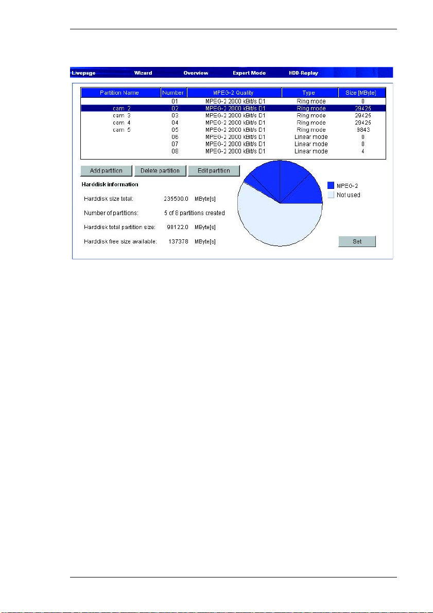
Chapter 5 Configuration using a Web Browser
Partitioning data
The VideoJet 8000 hard drive can have up to eight partitions configured in the
same way as is typical for computer hard drives. Parameters can be defined
individually for each partition, such as size, quality, type of video recording and
the compression standard used. Changes in these parameters result in a
complete reorganization, causing saved data on the partition to be deleted.
The VideoJet 8000 requires a dedicated partition for the recordings of each
camera connected. Each partition is linked to its own encoder or camera input:
camera input Video 1 with partition 01, camera input Video 2 with partition 02 etc.
The assignments cannot be changed. Therefore all partitions are always shown
in the list, regardless of whether a configuration is present or has been deleted.
It is necessary to configure all eight partitions to record with eight cameras. The
default configuration already has eight partitions configured.
All the partitions are listed in the table on the Partition page by name, sequential
number, recording format/video quality, recording type and partition size.
This page also provides an overview of the hard drive information, such as total
size, number of partitions, space used on the partitions and the number of
unallocated megabytes of space. A pie chart shows how much space is reserved
for recordings or is unused.
VideoJet 8000 83
Page 84
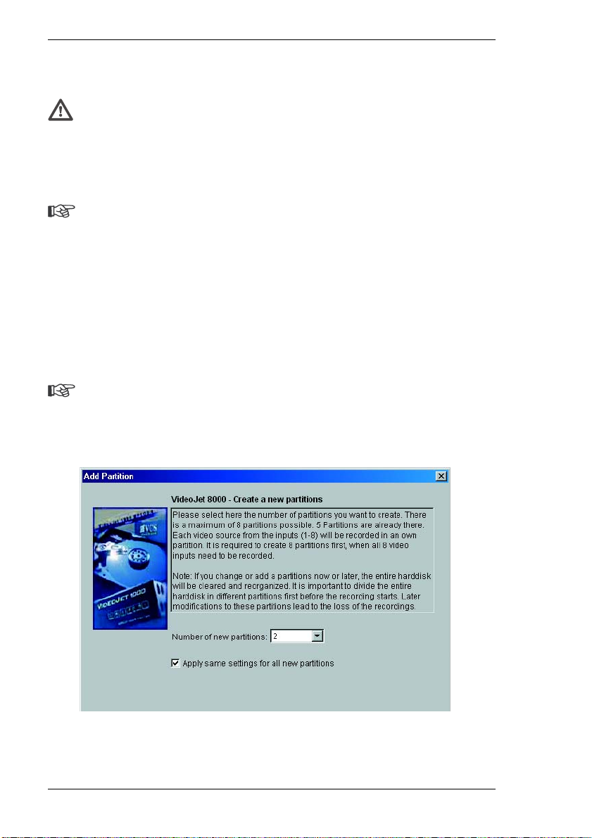
Configuration using a Web Browser Chapter 5
General procedure
Warning!
Changes to the size or number of partitions will result in reorganization of
the entire hard drive and the loss of all saved data. Therefore, before
making changes to the parameters mentioned, check the recordings and
back up the important sequences to your computer's hard drive.
Note
If there are already eight partitions configured, the Installation Wizard can
only be started after at least one partition has been deleted.
When the Installation Wizard has started, a new information window will appear
in which settings can be config ured.
The entire wizard sequence must be completed once for each hard drive partition
created. For this reason, the number of partitions to be created can be selected
immediately after starting the Installation Wizard. The wizard will then restart
automatically until all the partitions specified are configured.
Note
More than one partition with the same configuration can be created in a
single process. Mark the checkbox Apply same settings for all new
partitions on the initial page of the wizard.
– Click Add partition to start the partition wizard.
– Always read the information in the upper part of the window first.
84 VideoJet 8000
Page 85
Chapter 5 Configuration using a Web Browser
– Click in the text fields to enter values or use the other controls available, such
as buttons, check boxes or list fields.
– Click Next >> to continue to the next step.
– Click << Back to look at the previous step again.
Applying the settings
Note
Continue with the Installation Wizard until the last page. Only there is it
possible to save the settings by clicking Finish.
Settings made with the Installation Wizard only take effect after the Finish button
on the last page is clicked.
Clicking Cancel causes the original settings to remain unchanged.
– After closing the Installation Wizard, click the Set button in the main window to
send the changes to the unit and save them there.
Changing partition data
The configuration of the partitions can be changed at any time.
Warning!
Changes to a partition that affect the name, video quality, recording format
or type or the number of alarms and the pre- and post-alarm recording times
cause the partition to be reorganized and all saved data on that partition to
be lost. You should therefore back up all important sequences to the hard
drive of the computer before making such changes. If the total recording
time or the size of the partition is changed, the entire configuration of the
hard drive is lost.
The desired changes can be made in the Partition Settings window.
– Click to select the partition in the list that you want to change.
– Click Edit partition. The Partition Settings window will appear, showing the
information for the selected partition.
– Make the desired changes.
– Click Set to save the changes.
VideoJet 8000 85
Page 86

Configuration using a Web Browser Chapter 5
– After closing the window, click the Set button in the main window to send the
changes to the unit and save them there.
Deleting partitions
A partition can be deleted at any time.
Warning!
Deleting a partition causes the entire hard drive to be reorganized and all
sequences stored on it to be lost. Therefore, before deleting partitions,
check the recordings and back up the important sequences to your
computer's hard drive.
– Click a partition in the list to select it.
– Click Delete partition to delete the selected partition. The partition will not be
removed from the list. Rather, it remains without a name or size specification
in order to give you a better overview.
– Click Set to send the changes to the unit and save them.
86 VideoJet 8000
Page 87
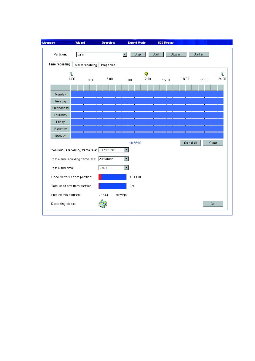
Chapter 5 Configuration using a Web Browser
Recording scheduler
Here you set the parameters for recording on the local hard drive. Recording may
be done continuously or only in the event of an alarm.
Partition:
Select the partition on which you want to record. Recording of the individual
camera inputs is always done on dedicated partitions.
Time recording
Here you can specify the times during which continuous recording on the hard
drive takes place.
For each weekday, there are separate selection fields for each partition and thus
for each camera input. You can select 16 individual recording periods for each
weekday.
VideoJet 8000 87
Page 88

Configuration using a Web Browser Chapter 5
Note
If a period has already been selected for the alarm recording, you can no
longer select it for timed recording (see Alarm recording, page 90).
– Left-click on the weekday on which the recording should start and hold down
the mouse button.
– Now drag the selected field to the desired ending time for the recording and
release the mouse.
– Right-click a selected time segment to delete it.
– Click Select all to select all time segments.
– Click Delete all to delete all selected periods.
Continuous recording frame rate:
You can select the frame rate for default recordings. Default recordings are those
that are not triggered by an alarm. The option All frames is used to record at
25 fps (PAL) or 30 fps (NTSC) from a camera to its assigned partition. Other
settings result in a lower frame rate and thus require less partition space. This
means that the VideoJet 8000 can record for a longer period of time.
Post-alarm recording frame rate:
If an alarm occurs during a default recording, the frame rate can be changed
automatically to the post-alarm rate. The option All frames is used to record at
25 fps (PAL) or 30 fps (NTSC) from a camera to its assigned partition. Other
settings result in a lower frame rate.
Post-alarm time:
Select the period after an alarm during which recording should continue at a
different frame rate.
Used file tracks from partition:
Up to 128 recording tracks are created automatically on a partition. Each new
recording takes place on a separate track.
Selecting the option Linear mode means that no more new recordings are made
after the 128 tracks have been used. Old recordings must be deleted before the
tracks can be re-used. Selecting Ring mode means that the 129th recording will
be written on the first track, so that the oldest recording is always overwritten by
the newest.
88 VideoJet 8000
Page 89

Chapter 5 Configuration using a Web Browser
Total used size from partition:
The display indicates the space currently used on the partition.
Free on this partition:
The display indicates the current amount of free space on the partition.
Recording status:
The icon indicates the recording status on this partition. When a recording is
being made, the icon is animated.
VideoJet 8000 89
Page 90
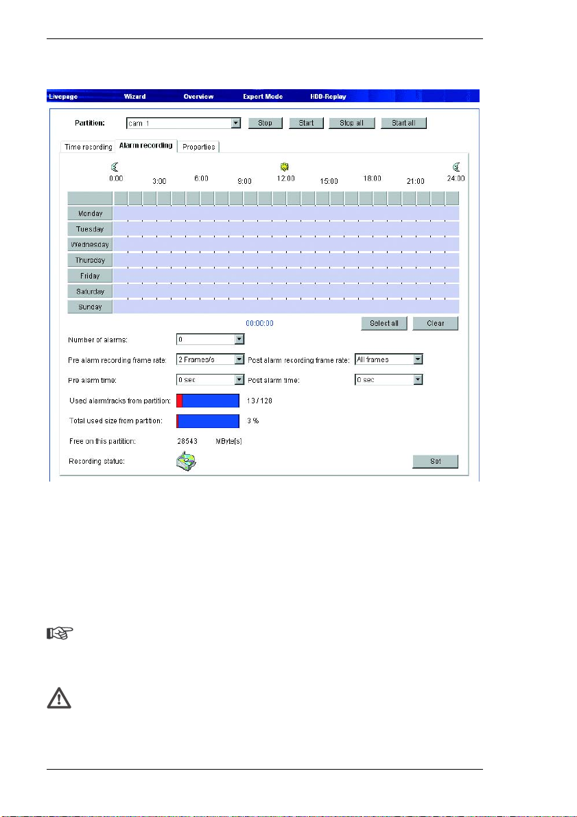
Configuration using a Web Browser Chapter 5
Alarm recording
Here you can define the times when recordings are to be made by the selected
camera on the hard drive in the event of an alarm. When recorded sequences are
played back, the time of the alarm activation is specially marked so that it can be
easily identified.
Just like for timed recording, you can select 16 separate time periods on each
weekday for alarm recording. An alarm recording takes place only during the
selected periods.
Note
If a period has already been selected for the timed recording, you can no
longer select it for alarm recording (see Timed recording, page 87).
Warning!
For alarm recordings, alarm tracks must be set up on the desired partition
(see Number of alarm tracks, page 91).
90 VideoJet 8000
Page 91

Chapter 5 Configuration using a Web Browser
The VideoJet 8000 uses a special recording mode for alarm recording to optimize
the use of storage capacity. As soon as a time slot begins for the alarm recording,
continuous recording starts on a segment the size of a complete alarm sequence
(pre- and post-alarm). This segment on the partition works like a ring buffer and
is overwritten again and again until an alarm is actually triggered. After that,
recording on this segment will go on for the time predefined for post-alarm
recording, and then a new segment will be used in the same way. For this reason
the recorded alarm file is always saved in its full length to the partition and the
recording space required for each alarm recording can be calculated easily.
Note
When the time slots for default and alarm recording overlap, the default
recording has priority.
Number of alarms:
Here you set the number of alarm tracks on the partition. One alarm event can be
recorded on each alarm track. The specified number of alarms can be recorded
and archived accordingly. A partition can contain a maximum of 128 alarm
recordings. If the option Ring mode is set for the partition, the predefined number
of the latest alarm recordings will be stored. If the option Linear mode is set,
recording will stop as soon as all the alarm tracks have been written.
Pre-alarm recording frame rate:
You can select the frame rate for pre-alarm recording. The option All frames is
used to record at 25 fps (PAL) or 30 fps (NTSC) from a camera to its assigned
partition. Other settings result in a lower frame rate.
Post-alarm recording frame rate:
You can select the frame rate for alarm recording. The option All frames is used
to record at 25 fps (PAL) or 30 fps (NTSC) from a camera to its assigned partition.
Other settings result in a lower frame rate.
Pre-alarm time:
Select the period to be covered by the pre-alarm recording.
Post-alarm time:
Select the duration of the alarm recording.
VideoJet 8000 91
Page 92

Configuration using a Web Browser Chapter 5
Used alarm tracks from partition:
The display indicates how many of the alarm tracks are already used.
Total used size from partition:
The display indicates the space currently used on the partition.
Free on this partition:
The display indicates the current amount of free space on the partition.
Recording status:
The icon indicates the recording status on this partition. When a recording is
being made, the icon is animated.
92 VideoJet 8000
Page 93
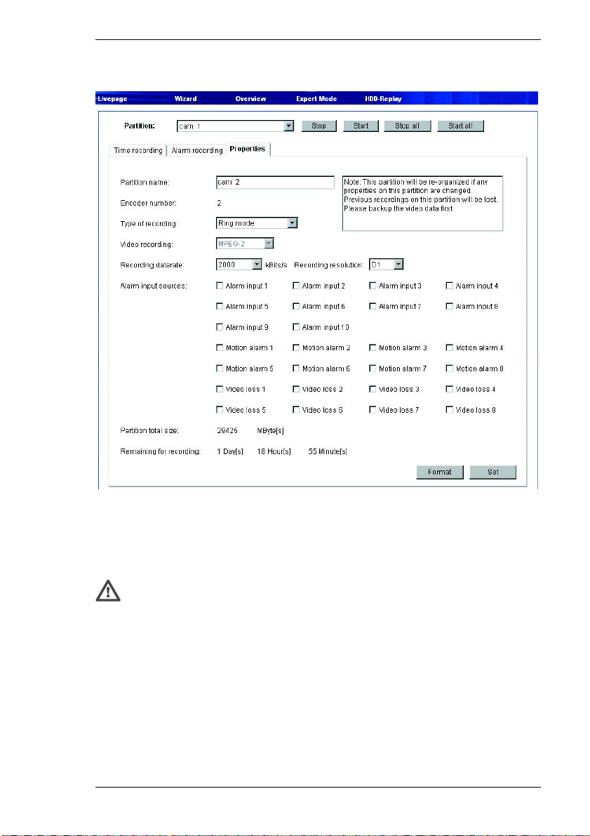
Chapter 5 Configuration using a Web Browser
Settings
You can view the current parameters for each selected partition and change them
as required in the recording scheduler. At the same time, you can activate the
various alarms which must be taken into account during the recording. You can
also set the data rate for the recording here.
Warning!
Changes to a partition that affect the name, video quality, recording format
or type or the number of alarms and the pre- and post-alarm recording times
cause the partition to be reorganized and all saved data on that partition to
be lost. You should therefore back up all important sequences to the hard
drive of the computer before making such changes.
Partition name:
Here you can enter a new name for the partition if needed.
VideoJet 8000 93
Page 94

Configuration using a Web Browser Chapter 5
Encoder number:
This shows information about the number of the associated encoder. The number
corresponds to the respective camera input on the back of the unit.
Type of recording:
You can change the recording mode as required. In Ring mode, recording will
continue indefinitely. When the maximum hard drive space has been reached,
the oldest recordings will be overwritten automatically. In Linear mode, recording
will continue until all the drive space has been used. Then recording will be
stopped until some old recordings are deleted to provide free space.
Recording data rate:
Select the desired recording rate here. The image quality increases automatically
as the data rate increases. However, a higher data rate reduces the recording
duration on the partition.
The maximum remaining recording time is recalculated after the data rate has
been set and is displayed further down the page (Remaining for recording).
Recording resolution:
Here you can change the image resolution for the recording as required.
Alarm input sources:
Here you can select the alarm sensors that should trigger an alarm. Select the
checkboxes of the alarm sources so the corresponding alarm sensors will be
monitored for alarm recording.
Note
A motion or video alarm from one camera can be used to trigger alarm
recording by another camera. The motion alarm must be configured on the
Motion Detector page (see page 98). Alarm inputs and the video alarms
are activated on the Alarm sources page (see page 96).
Partition total size:
The displayed value shows the total space in MB occupied by the partition on the
hard drive.
94 VideoJet 8000
Page 95

Chapter 5 Configuration using a Web Browser
Remaining for recording:
Here the maximum time remaining for recording is displayed. It is automatically
updated after the parameters are changed.
Deleting partitions
Partitions can be deleted at any time.
Warning!
Deleting a partition causes the entire hard drive to be reorganized and all
sequences stored on it to be lost. Therefore, before deleting partitions,
check the recordings and back up the important sequences to your
computer's hard drive.
– Click Format to delete the partition currently shown.
Activating partitions
After configuring a partition, it can be activated by clicking the Start button and
thereby starting recording activities.
After the partition is activated the entire field for it will be shown as gray. The icon
at the bottom of the page indicates the recording status on the partition. When a
recording is being made, the icon is animated.
Recording activities can be stopped at any time, and one, several or all partitions
can be deactivated.
– Click Start to activate the currently selected partition and begin recording
activities for it.
– Click Start all to activate all the configured partitions and begin the associated
recording activities.
– Click Stop to deactivate the currently selected partition and terminate its
recording activities.
– Click Stop all to deactivate all the configured partitions and halt the associated
recording activities.
VideoJet 8000 95
Page 96
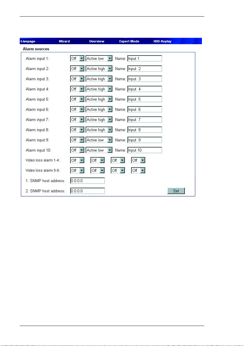
Configuration using a Web Browser Chapter 5
Alarm sources
You can configure the possible alarm triggers for the VideoJet 8000 (such as
alarm inputs and video signal monitoring of the camera inputs).
Alarm input 1 ... Alarm Input 10:
Select the option On in order to activate the alarm via the corresponding external
alarm sensor. Otherwise, select Off.
You can choose whether the alarm is triggered by an Active high or Active low
voltage level.
Name:
You can enter a name for each alarm input, which is then displayed next to the
icon for the alarm input on the video live page during the respective configuration
(see page 106).
96 VideoJet 8000
Page 97
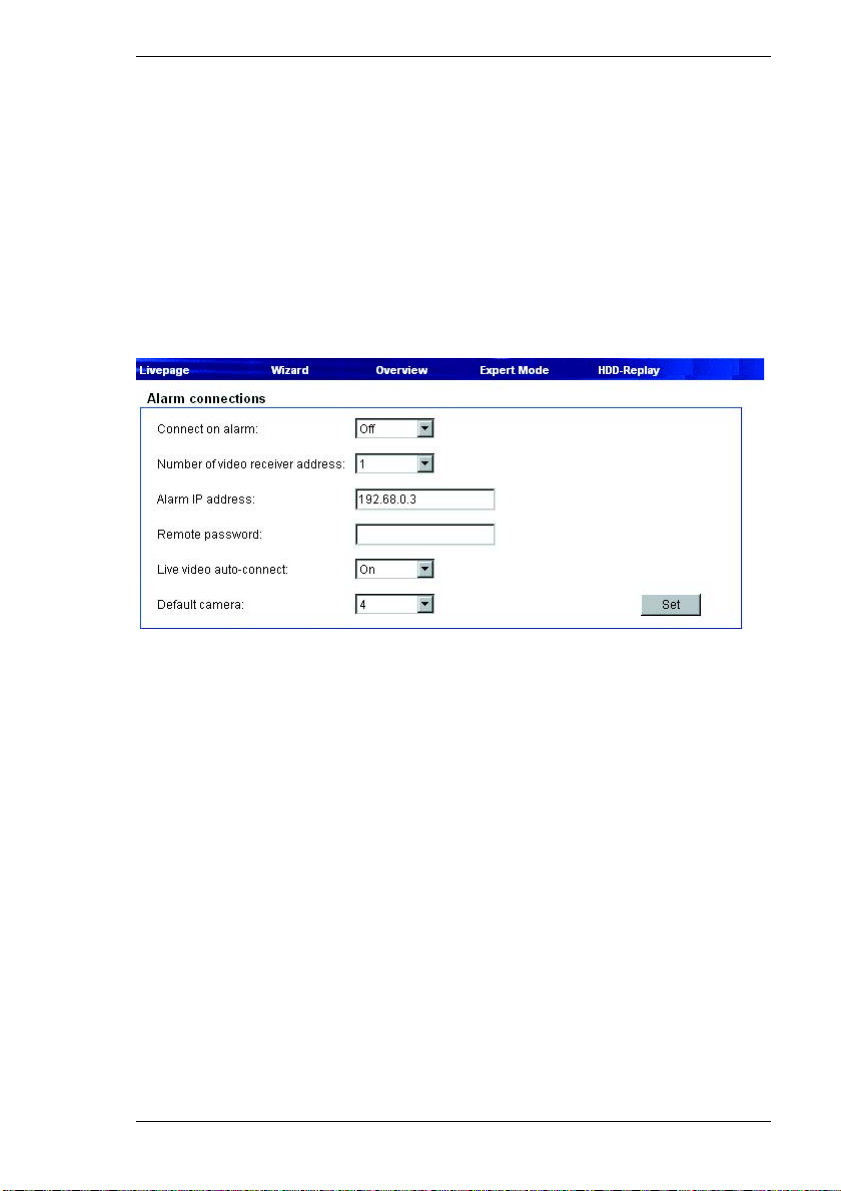
Chapter 5 Configuration using a Web Browser
Video loss alarm 1-4 ... Video loss alarm 5-8:
Select On if the VideoJet 8000 is to give an alarm when the video signal is
interrupted.
1./2. SNMP host address:
Enter the IP addresses of up to two chosen receivers here if the alarm message
is to be sent via SNMP-traps.
Alarm connections
You can select a number of options for the response of the VideoJet 8000 to an
alarm. In case of an alarm, the VideoJet 8000 can establish a connection to a
predefined IP address (VCS hardware receiver or PC with receiver software)
automatically. You can enter up to 10 IP addresses which will be selected in
sequence by the unit until a connection is established. You can also choose
which camera image should be automatically be displayed first on the receiver in
the case of an alarm.
Connect on alarm:
Select On so that the VideoJet 8000 establishes a connection automatically to
one of the pre-defined IP addresses in the event of an alarm.
Number of video receiver address:
Here you assign the numbering for the IP addresses to be contacted in the event
of an alarm. The unit contacts the remote locations on e after the other in the
numbered sequence until a connection has been established.
VideoJet 8000 97
Page 98

Configuration using a Web Browser Chapter 5
Alarm IP address:
For each number, enter the corresponding IP address of the desired receiver.
Remote password:
If necessary, enter the password, if the remote location is protected by a
password.
Live video auto-connect:
Select On if an active connection should be reestablished automatically to one of
the previously specified IP addresses after each restart, e.g. after a connecti on
breakdown or network dropout.
Default camera:
Here you can select the camera whose image will automatically be displayed first
to the receiver after the alarm connection has been established. Depending on
the system configuration, the receiver can then also select the other cameras.
Motion detector
The VideoJet 8000 has an integrated video sensor which can detect changes in
the signal. Such changes are due primarily to movements in the camera's field of
view.
The video sensor can be configured separately for each encoder, i.e. for each
camera connected.
98 VideoJet 8000
Page 99
Chapter 5 Configuration using a Web Browser
The sensitivity of the video sensor can be adjusted, so an alarm is generated only
if specified values are exceeded.
In order for the sensor to function, the following conditions must be met:
] The motion detector must be enabled.
] At least one cell must be activated.
] The individual parameters must be set for the operating environment and the
desired responses configured accordingly.
] The sensitivity must be set to a value greater than zero.
Warning!
Reflections of light (off glass surfaces, etc.), switching lights on or off or
changes in the light level caused by cloud movement on a sunny day can
trigger unintended responses from the video sensor and generate false
alarms. Run a series of tests under day and night conditions to ensure that
the sensor works as intended.
For indoor surveillance, ensure constant lighting of the areas during the day
and at night.
Uniform surfaces without contrast can trigger false alarms even with
constant lighting.
– Click one of the tabs to access the configuration of the corresponding
encoders (or camera).
– Click Reset in the Default settings area to revert the settings to their default
values.
– Click the remaining tabs to access and edit the configurations of additional
encoders.
Motion detector Select On to activate the video sensor.
Sensor fields
The areas of the image to be monitored by the video sensor can be selected. The
video image is subdivided into 192 square sensor fields. Each of these fields can
be activated or deactivated individually. If it is necessary to exclude particular
regions of the camera's field of view from monitoring due to continuous
movement (by a tree in the wind, etc.), the relevant fields can be deactivated.
VideoJet 8000 99
Page 100

Configuration using a Web Browser Chapter 5
– Click Select area to configure the sensor fields. A new window will open.
– If necessary, click Clear all first to clear the current selection (fields marked
red).
– Click the fields to be activated. Activated fields are marked red.
– Click Select all to select the entire video frame for monitoring.
– Right-click any fields you wish to deactivate. "Inactive" fields are marked white.
– Click Set to save the configuration.
– Click the close button (X) in the window title bar to close the window without
saving the changes.
Local sensitivity
The basic sensitivity of the video sensor can be adjusted to the environmental
conditions of the camera.
The sensor reacts to variations in the brightness of the video image. The darker
the observed area, the higher the value that must be selected.
– Adjust the sensitivity by dragging the scroll thumb to the desired setting.
Average [n frames]
You can define the number of frames for which a movement is monitored before
generating an alarm. This helps prevent false alarms from events such as a bird
flying across the surveillance area.
– Select the desired value by dragging the scroll thumb to the desired position.
Alarm area size:
You can specify the number of sensor fields that a moving object must cover to
generate an alarm. This is to prevent objects that are too small from triggering an
alarm.
The minimum setting is "1". This corresponds to one sensor field.
– Select the desired value by dragging the scroll thumb to the desired position.
Motion alarm status:
This field lists all the motion alarms and the date and time of their occurrence. The
events for the currently selected camera input will be listed.
100 VideoJet 8000
 Loading...