

Page 1
SPARE PART AND OPERATION MANUAL
Form 109 (08/10)
FOOD MIXER
Model W80, W100N, W150PL
1993 to Present
Page 2

Caution -READ BEFORE OPERATING- Caution
Varimixer recommends that mixer operators be at least 18 years of age and be thoroughly trained
on the use of the mixer.
Varimixer recommends that the following precautions be adopted to help make the mixer operation
safer and more efficient.
........- All operators should be at least 18 years of age.
- All operators should be thoroughly trained before being allowed to operate the mixer.
- NEVER reach into the bowl when the mixer is running.
- Do not wear loose clothing or rings while operating the mixer.
- Stop the mixer and lower the bowl before adding ingredients, scraping the bowl, removing the
............agitator, or removing the product.
- Stop the mixer before removing or installing attachments into the drive hub.
- Do not attempt to assemble or disassemble attachments while mounted into the drive hub.
- Always use the pusher plate with the slicer/meat grinder attachments.
- NEVER bypass the safety mechanisms supplied on the mixer. Doing so can cause injury and
............is the responsibility of the user to insure these safety mechanisms are operating properly.
1
Page 3

LIMITED WARRANTY
Varimixer warrants its commercial mixers to the original purchaser against defects in material or manufacture for a period of one
year from the date of original purchase, subject to the following exclusions and limitations.
EXCLUSIONS
The warranties provided by Varimixer do not apply in the following instances:
1. In the event that the equipment is improperly installed. Proper installation is the responsibility of the installer, proper installation
procedures are covered in the Varimixer Spare Parts and Operations Manual. .
2. In the event that the equipment is improperly maintained. Proper maintenance is the responsibility of the user. Proper maintenance procedures are covered in the Varimixer Spare Parts and Operations Manual.
3. In the event that failure or malfunction of the appliance or any part thereof is caused by abnormal use or is otherwise not attributable to a defect in material or manufacture. .
4. In the event that the appliance , by whatever cause, has been materially altered from the condition in which it left the factory.
5. In the event that the rating plate has been altered or removed.
6. On parts which would normally be worn or replaced under normal conditions. .
7. With regard to adjustments and/or calibrations. Checking of and changes in adjustments and calibrations are the responsibility of
the installer, Proper installation is the responsibility of the installer, proper installation procedures are covered in the Varimixer
Spare Parts and Operations Manual.
..THIS LIMITED WARRANTY IS EXCLUSIVE AND IS IN LIEU OF ALL OTHER WARRANTIES WHETHER ..
..WRITTEN, ORAL OR IMPLIED, INCLUDING, BUT NOT LIMITED TO, ANY WARRANTY OF..
..MERCHANTABILITY OR FITNESS FOR PARTICULAR PURPOSE OR WARRANTY AGAINST LATENT.. ..
DEFECTS.
LIMITATIONS OF LIABILITY
In the event of warranty claim or otherwise, the sole obligation of Varimixer shall be the repair and/or replacement at the option of
Varimixer, of the appliance or component or part thereof Such repair or replacement shall be the expense of Varimixer except that
travel over 100 miles or two hours, overtime, and holiday charges shall be,, the expense of the purchaser. Any repair or replacement
under this warranty does not constitute an extension of the origin, warranty for any period for the appliance or for any component
part thereof. Parts to be replaced under this warranty will be repaired or replaced at the option of Varimixer with new or functionally
operative parts. The liability of Varimixer on any claim of any kind, including claims based on warranty, expressed or implied, con-
tract, negligence, strict liability or any other theories shall be solely and exclusively the repair or replacement of the product as stated
herein, an such liability shall not include, and purchaser specifically renounces any rights to recover, special, incidental, consequen-
tial or other damages of any kind whatsoever, including, but not limited to, injuries to persons or damage to property, loss of profits
or anticipated profits, or loss of use of the product.
TO SECURE WARRANTY SERVICE
If you claim a defect covered by this Limited Warranty, first direct your claim to the local Authorized Service Agency, giving model,
serial and code numbers, voltage, a description of the problem and your sales slip. If this procedure fails to be satisfactory to you,
you may write to the Varimixer National Service Manager, 5489 Campus Dr, Shreveport, Louisiana 71129; you should include the
information listed above.
2
Page 4

TABLE OF CONTENTS
W80-W100PL
Installation Instructions...................................................................................................4
Operating Instructions.....................................................................................................5
Cleaning-Maintenance....................................................................................................6
Belt Adjustments and Removal.......................................................................................7
Adjusting the Bowl Height...............................................................................................8
Capacity Chart................................................................................................................9
Machine Column......................................................................................................11-14
Bowl Arms................................................................................................................15-18
Planetary Head........................................................................................................19-20
Transmission...........................................................................................................21-22
Speed Lever Assembly............................................................................................23-24
Attachment Drive....................................................................................................25-26
Bowl Screen.............................................................................................................27-28
Instrument Panel....................................................................................................29-32
Accessories.............................................................................................................33-34
Electrical Diagrams..................................................................................................35-40
W150PL
W150PL Manual..........................................................................................................42
3
Page 5
Read this page entirely BEFORE beginning installation.
VARIMIXER INSTALLATION INSTRUCTIONS
UNDER NO CIRCUMSTANCES ARE THE SPEED LEVER, BOWL LIFT LEVER, OR THE BOWL
ARMS TO BE USED TO MOVE THE MIXER INTO PLACE. DAMAGE WILL RESULT TO THE UNIT.
IT IS RECOMMENDED THAT THE TOP LID BE REMOVED BEFORE MOVING THE UNIT.
The mixer must be mounted with the rubber feet, which neutralize both shaking and rusting. Spacers
can be inserted under the mixer’s feet if the floor is uneven. The mixer can be bolted to the floor if d
esired.
Before the mixer is connected to power, it should be checked that the voltage and frequency on the
rating plate is correct in relation to the place of installation. A unit labeled 220V 3 Phase will operate
from 208V to 240V 3 phase safely. The rating plate is located on the rear right side of the mixer. The
electrical connection box is located at the top rear of the mixer.
WARNING
Electrical and grounding connections must comply with applicable portions of the National Electrical
Code and/or other local electrical codes................................................................ire
Wire Color Codes
White-Phase 1
Red -Phase 2
Black-Phase 3
Green-Ground
No Neutral is used in the United States and Canada
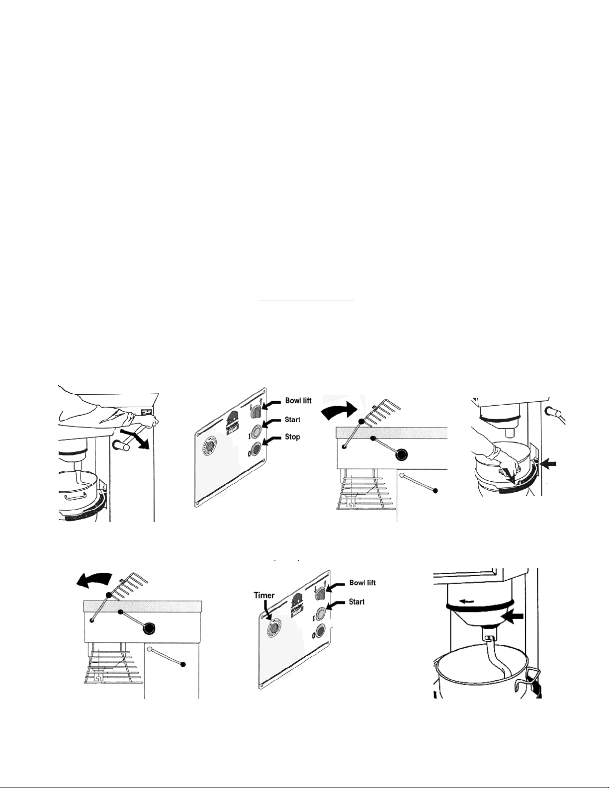
1. Lower the bowl using the bowl lift lever or the
bowl lift switch on the front panel.
4. Close bowl screen and raise
the bowl arms into the up
position.
5. Turn timer to 10 minutes and
push “start” .
2. Open the bowl screen.
4
3. Remove the bowl
and tools.
6. Insure cover is rotating in
the correct direction.
Page 6
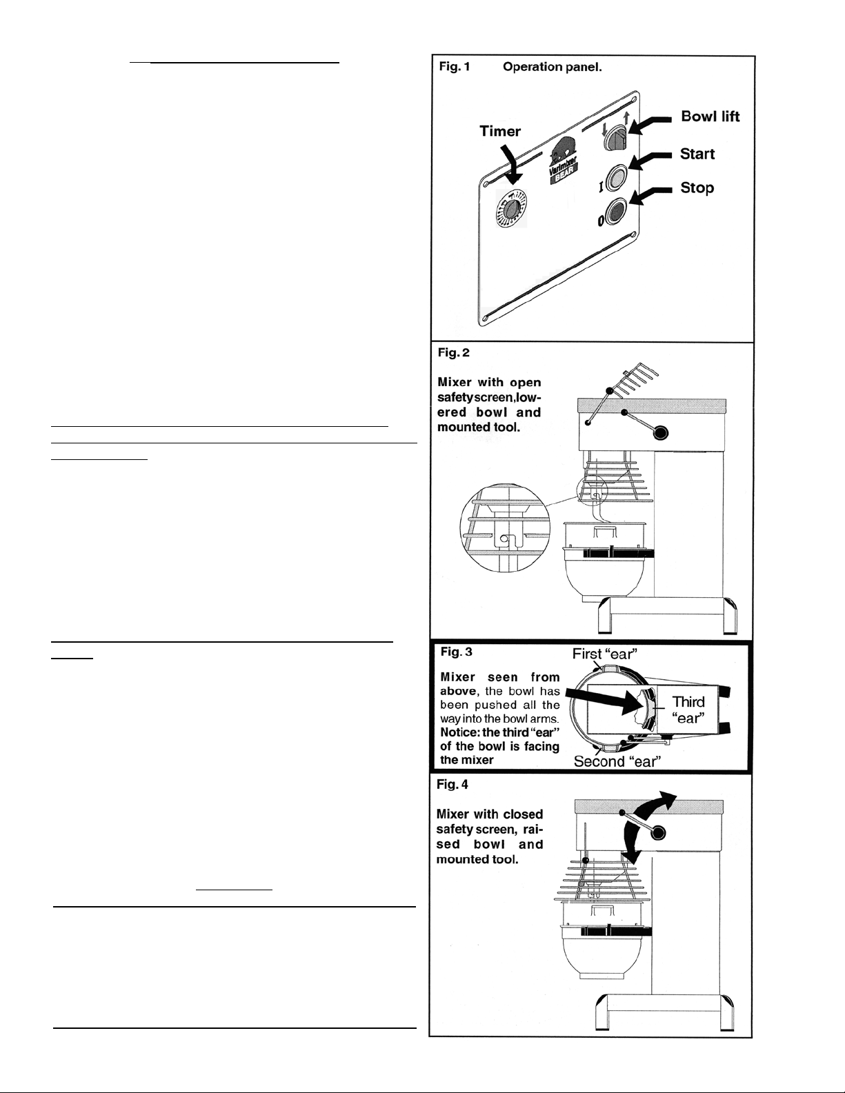
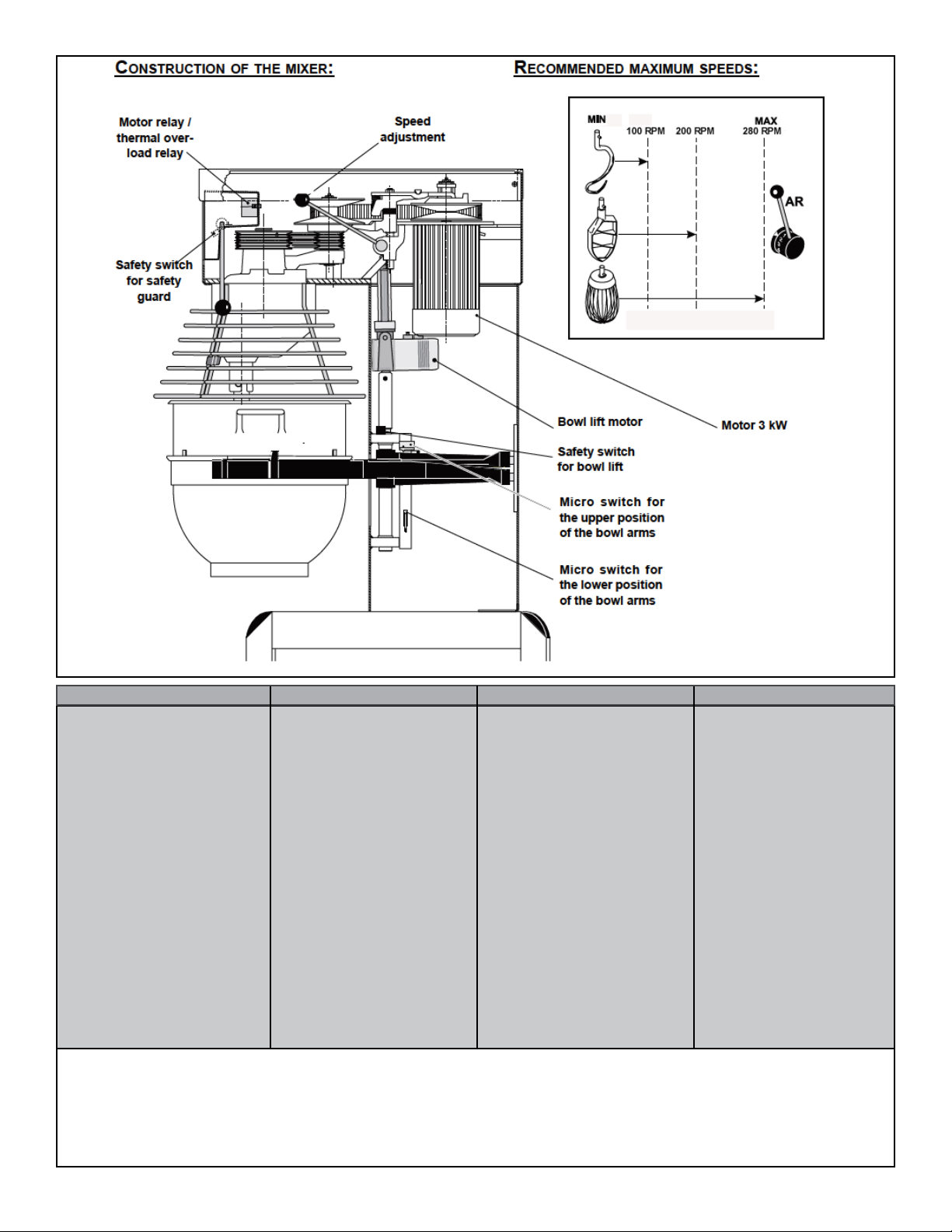
OPERATION OF THE MIXER:
A) Open the bowl screen and place the bowl in the bowl
arms. Note: The bowl arms must be in lowest position and
the bowl must be pushed all the way into the bowl arms.
(Fig.3).
B) Place the mixing tool in the bayonet shaft. The pin on
the tool must be turned into the bayonet hole (fig.2).
C) The bowl is raised to working position by a clockwise
turn of the button for bowl lift. Ensure that the bowl is
placed correctly. Close the bowl screen. If the mixer is
equipped with a timer, set the mixing time required by turning the timer (fig 1) clockwise. The mixer will stop automatically, when the time runs out. When the mixer has timed
out, the "procedure for starting after emergency stop" is
used before the mixer is re-started.
D) Start the mixer by pressing the green start button
(fig.1)
The mixer will only start when the bowl is in the "up"
position, the bowl screen is "closed", and the timer is set to
"time" or "hold".
E) Turn the speed selector lever (fig. 4) to the rear until
the required speed has been obtained, (notice the recommended maximum speeds on page 3).
F) Before the mixer is stopped, the speed selector lever
must be moved back to lowest speed (fig.4).
G) Stop the mixer by pressing the red stop button (fig.1)
PROCEDURE FOR STARTING AFTER EMERGENCY
STOP:
1) This procedure must be used in cases where the mixer
has been interrupted in high speed.
2) Lower the bowl and remove the tool from the bayonet.
3) Raise the bowl arms, either empty or with the bowl.
4) Close the bowl screen, start the mixer and move
the speed selector lever back to lowest speed. Switch off
the mixer. Now the mixer can be started as usual.
OVERLOAD
Do not overload the mixer. Sticky and heavy doughs may
reduce the capacity of the bowl by 75%. The capacity is
further reduced if the speed of the mixing tool is increased
beyond recommended values or if an incorrect mixing tool
is used. Large lumps of fat or cooled ingredients MUST be
cut into small parts before they are placed into the bowl or
damage can occur to the mixing tool(s).
5
Page 7
Correct use of tools:
Whips should never be struck
against hard objects, this will
decrease the life of the tool.
Recommended applications for tools:
Whip Beater Hook
Cream
Egg Whites
Mayonnaise
and the like.
Cakes
Waffles
Muffins
and the like.
Pizza
Bread
Donut
Doughs and
the like.
Cleaning:
The mixer should be cleaned daily or after use.The
mixer should be cleaned with a soft cloth and clean
water. Sulphonated soaps should be used with caution
as they destroy the mixer's lubricants.
Maintenance and Lubrication:
The variable speed pulleys must be lubricated regularly, i.e. a
lubrication interval of approx. 60 hours of operation or once a
week.
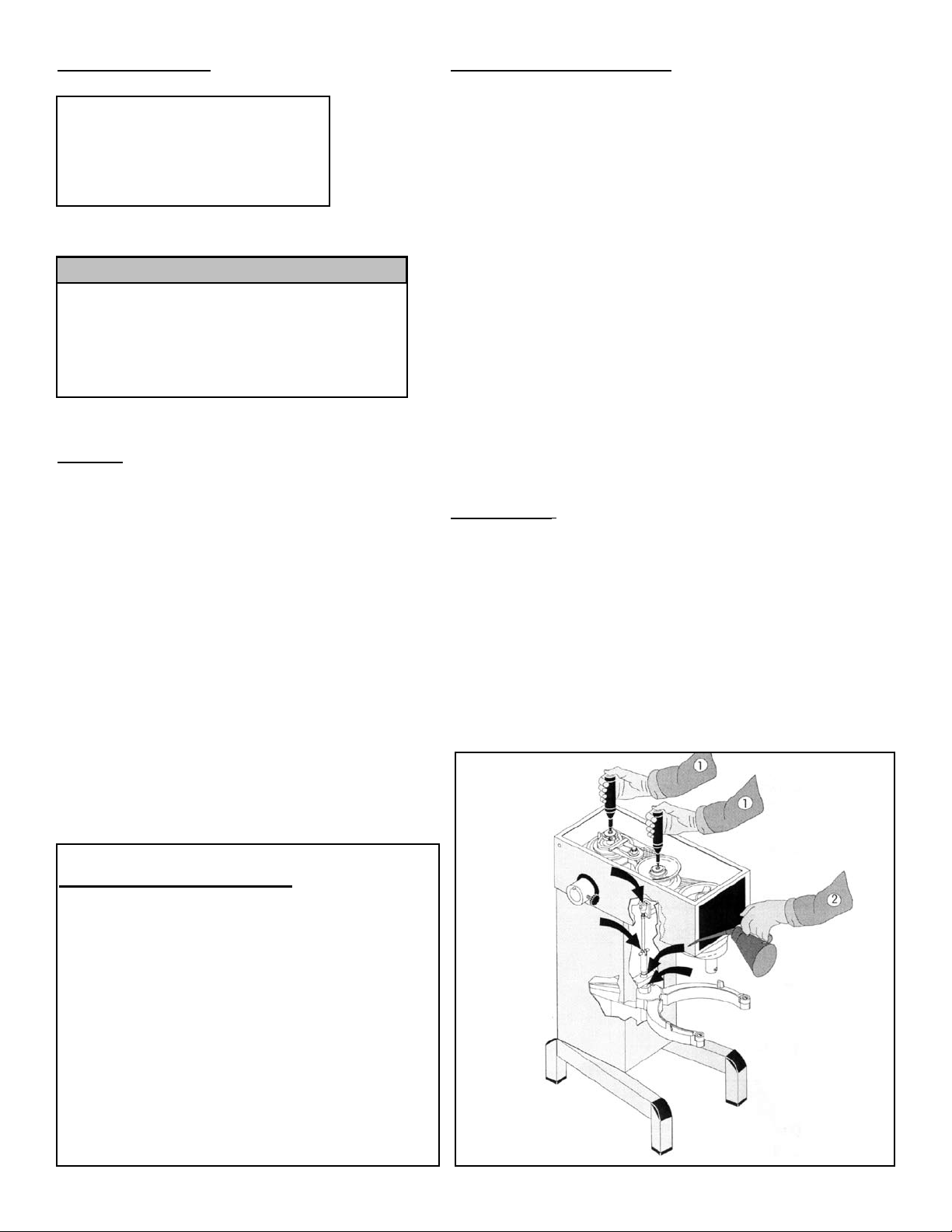
Lubrication of variable speed pulleys:
-Start the mixer and increase the speed to approx. 50%. Stop
the mixer and open the lid on the top of the mixer. On the top of
each of the two pulley set shafts is a grease nipple (fig. 5 point
1). Press grease through the grease nipples until the grease
gun feels hard to press or until grease comes out between the
shaft and the pulleys.
-Start the mixer, and set the speed back to low ..speed.
-Stop the mixer and fill the grease gun with new grease so that
it is ready for next time.
Lubrication of other movable parts:
The movable parts of the bowl arms, the shaft and the lifting
rod must also be lubricated with oil. Remove the rear covering
and lubricate the marked points with an oil can. (fig.5 pkt.2)
Grease Types:
-Grease for the pulley set shafts: Lubriplate # 1200-2
Never use high pressure cleaning for the mixer.
Bowls and tools of aluminium must not be washed with
strong alkaline detergents (pH not to exceed 9.0).
The soap suppliers can recommend the correct type of
soap.
The mixer should be unplugged before cleaning to prevent accidental starting while cleaning.
The inside of the beater shaft should be cleaned once
a day with warm, soapy water.
Dough hook Cleaning: Special care
should be given to cleaning the dough
hook. We recommend that it be
cleaned and sanitized in a commercial
dish machine. An alternate cleaning
procedure is to vigorously scrub the
hook with a hot.water and detergent
solution. Use a heavy bristled brush.
After cleaning, sanitize the hook by
rinsing it with a 50 ppm solution of
sodium hypochlorite.
-On repair of the planetary head: Grease the toothed wheel and
the toothed rim with Nye Gel 868VH,(PN 868VH), the needle
bearings in the planetary head must not be lubricated with this
type of grease, they should be lubricated with PN Sapphire 2.
Do not use any another type of grease than the one stated
here.
-On repair of the attachment drive: Fill the attachment drive with
Tribol Molub 860/150-0, (PN 860/150-0).
Fig.5
6
Page 8
List of Errors
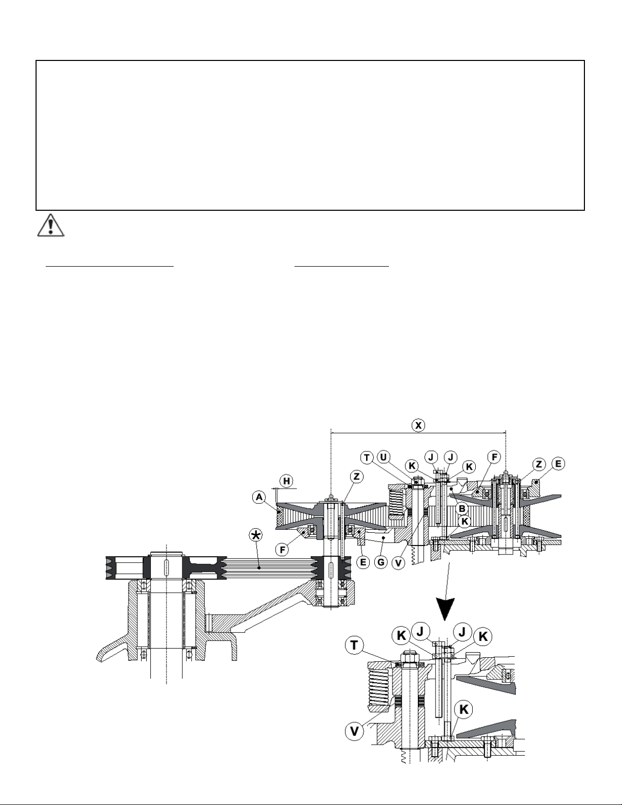
Adjustment of special v-belt:
The distance (X) is only indicative as it depends on the tolerance of the special V-belt
.
1. Start by tightening the v-belts (*).
2. Ti ghte n th e spe c ial V- belt (A) by m o vin g
one or two washers from (V) to (T).
3. Star t th e mix e r a n d le a ve i t ru n nin g whi l e
the nut (U) is tightened completely.
4. On t h e f r ont p ull e y se t th e stu d (E ) on t he
va r ispe e d c o llar (F) must be p lace d in s ide t he
lower fork (G) and on the rear pulley set outsi d e th e fo r k fo r be l t ti g hte n er ( B ), ( both mus t
point backwards).
5. Tol eran c es i n th e tr a nsmi s sio n mig h t c a use
the special V-belt (A) to hit the pins (Z) of the
pulley sets when the speed has been adjusted. In such cases the distance (X) must be
reduced. (+ or - 1/8" of 12 1/4")
6. Then follow the section: “Adjustment of
speed”
Possible Solutions
A rattling sound from the closed part of the mixer. Adjustment of special v-belt
The mixer starts “striking” when kneading dough Adjustment of special v-belt
which normally causes no problems.
The mixer changes its speed by itself. Adjustment of special v-belt
The minimum and the maximum speeds are changing. Adjustment of speed.
The bowl is too tight or too loose. Adjustment of bowl xing
The tool hits the sides of the bowl.
Adjustment of bowl centering
...................................................................................................................................or damaged tool.
The tool hits the bottom of the bowl. Adjustment of bowl height
...................................................................................................................................or damaged tool.
Prior to a possible repair or adjustment, switch off the mixer by disconnecting the power cable.
Adjustment of speed:
1 . Th e st o p sc r ews (J) o n t h e sp e ed l ever shou ld b e adj u ste d so
th a t th e me a sure m ent (H) i s 1 / 8" o n th e fro n t a n d th e re a r pu l ley,
at low a nd h igh s pee d , re s pec t ivel y. Tigh t en t h e c o unte r nu t s (K )
when the speed is correctly adjusted.
2. Tolerances in the transmission might cause that the special
V-belt (A) is hitting the pins of the pulley sets (Z) when the speed
has been adjusted. In such cases the distance (X) must be reduced, see “Adjustment of special v-belt”, and the speed must
be readjusted.
(X) W80 = 12 1/4" +/- 1/8"
(X) W100 = 12 1/4" +/- 1/8"\
(X) W150 = 12 1/4" +/- 1/8".
7
Page 9
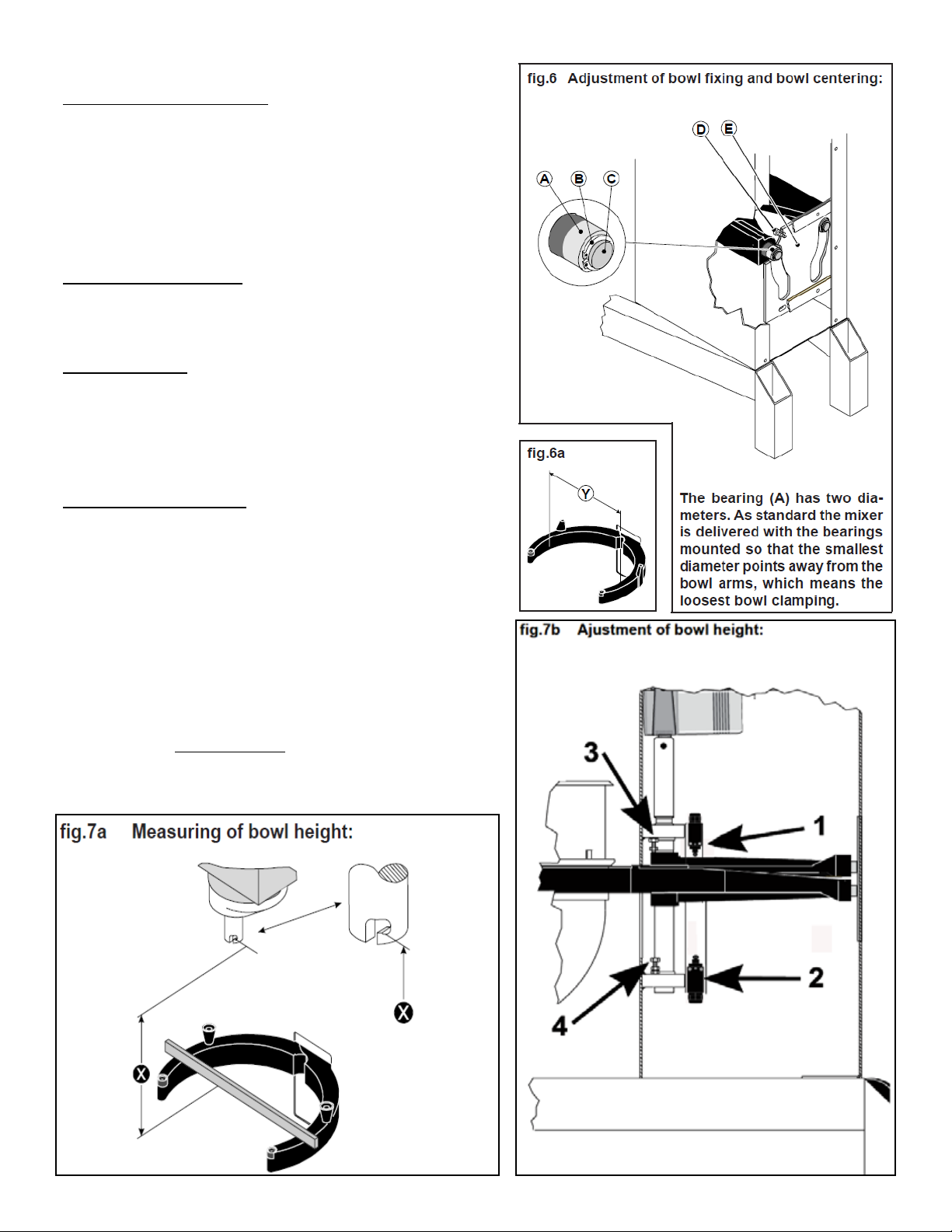
Adjustment of bowl centering:
First find the present bowl centering: mount the beater and the
bo w l, t h en r aise the bowl arm s up t o n o rmal wor k ing p osi t ion. With
yo u r ha n d t u rn t h e b e ater, a nd t hen m eas u re t h e d i stan c e b e twee n
be a ter a nd b owl e dge . By r emo v ing t he r ear c ove r ing, the bowl
ar m gui d e p l ate i s n o w ac c ess i ble ( E). Loos e n t h e sc r ews (D) a nd
mo v e th e bo w l ar m gu i de p l ate in t h e r e quir e d d i rect i on. A g ain
turn the beater and measure the distance between beater and
bowl. When the bowl has been centred, fasten the bowl arm guide
plate in the new position and screw on the rear covering.
Adjustment of bowl fixing:
Th e bow l ar m s mu s t b e rai s ed t o no r mal work i ng p osit i on. The
ad j usti n g d i amet e r ( Y ) sh a ll b e me a sur e d in s ide betw e en t he b o wl
arms (fig.6a):
Adjusting diameter (Y): W80 = 20 3/8"
W100 = 21 13/16"
In case the bowl fas t enin g is too l oos e , re m ove the l ock ring (B)
and draw the bearing (A) from the shaft (C). The bearing should
be turned 180 degrees and be mounted on the shaft again. It
mi g ht b e ne c essa r y t o tur n bo t h be a rin g s. At l ast chec k th e bow l
centering and if necessary, adjust.
Adjustment of bowl height:
The distance (X) is measured from the bottom side of the bayone t hol e to the s urf a ce o n th e bow l ar m s on whi c h th e bo w l re s ts
(fig.7a). The bowl arms must be lifted to normal working position.
Bowl height (X): W80 = 9 1/4"
W100 = 11 3/4"
The upper and lower position of the bowl is determined by micro
sw i tch ( 1) a nd ( 2 ), ( fig. 7b) . Th e tw o mec h anic al s t ops c ons i stin g
of the b olt s (3) and (4) a re a djus t ed s o th a t t h ey w i ll b e hi t app rox.
1 m m af t er t he m i cro swit c h, i n ca s e t h e mi c ro s witc h sh o uld f ail.
Th e low e r p o siti o n i s adj u ste d fir s t; b y sl i din g the ent i re b r acke t
as s embl y up or d o wn o n th e sl o ts o n th e bra c ket (2). The upp e r
position of the bowl arms is adjusted by adjusting the up position micro switch mounting bracket ( 2 ) up or d own; it i s of utm o st
importance that the stop screw (3) is re-adjusted afterwards.
8
Page 10
Product W80 W100 W150
Dough, Bread-65%AR
Dough, Pizza-50% AR
Dough, Donut-Yeast
Dough, Donut-Cake
Pie Dough
Cookie, Dough
Muffins
Mashed Potatoes
Pancakes, Waffles
Whipped Cream
Cake, Layer
Eggs & Sugar
Icing , Fondant
Egg Whites
Cake, Cup
Cookies, Sugar
% AR=weight of liquids
weight of flour
105 Lbs.
90 Lbs.
80 Lbs.
60 Lbs.
69 Lbs.
68 Lbs.
90 Lbs.
58 Lbs.
35 Qts.
16 Qts.
92 Lbs.
40 Lbs.
50 Lbs.
2.5 Qts
140 dz.
132 dz.
Water weights
1 Gallon =8.33 lbs.
1 Quart =2.08 lbs
1 Pint (16 oz.) =1.04 lbs.
1 Cup
= .52 lbs.
155 Lbs.
135 Lbs.
150 Lbs.
140 Lbs.
95 Lbs.
105 Lbs.
125 Lbs.
76 Lbs.
44 Qts.
20 Qts.
125 Lbs.
57 Lbs.
76 Lbs.
3 Qts.
178 dz.
171 dz.
Batch size and/or speed reduction
may be necessary due to one of the
following conditions:
1.High Gluten Flour-Reduce batch
size by 10%
190 Lbs.
175 Lbs.
170 Lbs.
225 Lbs.
135 Lbs.
160 Lbs.
195 Lbs.
110 Lbs.
50 Qts.
32 Qts.
175 Lbs.
80 Lbs.
105 Lbs.
4 Qts.
250 dz.
240 dz.
2.AR % under 40%-Reduce batch size
by 10%
3.Water temp under 65 Degrees F
4.USE OF ICE REQUIRES A 10%
REDUCTION IN BATCH SIZE.
5. Speed should not exceed 100 RPM
when mixing dough.
9
Page 11

Notes:
10
Page 12
11
Page 13

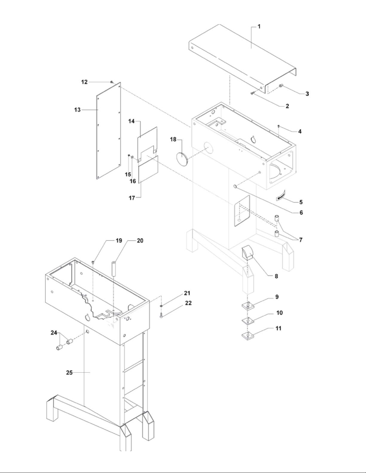
Machine Column W80-W100
Fig.
No.
1.
2.
3.
4.
5.
6.
7.
8.
9.
10.
11.
12.
13.
14.
15.
16.
17.
18.
19.
20.
21.
22.
23.
24.
25.
Description
Top Lid
Screw for Lid M6x20
Threaded Bushing
Ground Screw
Arrow Label
Plug Button
Bushings for Bowl Arm Shaft
Knee Pad
Foot
3MM Foot
6MM Foot
Screw M6X10
Rear Panel
Upper NSF Plate
Lock Nut
Washer
Lower NSF Plate
Plug Button f/ No Hub
Plug Button
Motor mount shaft
Washer
Bolt
N/A
Bushings for Bowl Lift Lever
Machine Column
W80
100-21
STA 5017
STA 6580
STA 5232
15-214
STA 6519
STA 2526
80-212
80N-213
80N-214.3
80N-214.6
STA 5080
100N-22.7
81-270
STA 5834
STA 6027
81-271
15-71
NLA
81-148
STA 6056
STA 5625
N/A
STA 2515
81-22
W100
100-21
STA 5017
STA 6580
STA 5232
15-214
STA 6519
STA 2526
80-212
80N-213
80N-214.3
80N-214.6
STA 5080
100N-22.7
101-270
STA 5834
STA 6027
101-271
15-71
NLA
81-148
STA 6056
STA 5625
N/A
N/A
81-22
12
Page 14

13
Page 15

Bowl Lift Microswitches W80-W100
Fig.
No.
1.
2.
3.
4.
Description
Microswitch Bracket (Manual Lift)
Microswitch
Screw
Microswitch Bracket Assembly
(Power Bowl Lift)
W80
81-612
81-173
STA 5270
81-174
W100
N/A
N/A
N/A
81-174
14
Page 16

15
Page 17

Manual Bowl Lift (W80 Only)
Fig.
No.
1.
2.
3.
4.
5.
6.
7.
8.
9.
10.
11.
12.
13.
14.
15.
16.
17.
18.
19.
20.
21.
22.
23.
24.
24A.
25.
26.
27.
28.
29.
.
Description
Lift Nut
Crank Arm
Bowl Arm Shaft
Lifting Rod
Lift Spring
Key
Snap Ring
Snap Ring
Screw
Nut
Pin
Pin
Roller
Lift Lever
Ball
Shaft
Roller
Bowl Lift Dampener
Bowl Arm Giude Plate
Cotter Pin
Pin For Lift/Dampener
Upper Mounting Bracket F/Dampener
Cotter Pin
Bowl Arm Left (facing unit front)
Bowl Arm Right (facing unit front)
Bushings for Bowl Arms
Eye Bolt for Bowl Arm Spring
Roller Shaft
Nut
Washer
W80
15-65
60-63
81-68
81-83
60-110
STA 2020
STA 3408
STA 3462
STA 5088
STA 5827
STA 6205
STA 6370
31-128
100-62M
STA 3308
81-71.10
81-71.5M
81-600M
81-71
STA 6205
81-67.1
81-86.42
STA 6205
81-23
81-24
STA 2526
STA 5550
31-127
STA 5819
STA 6044
16
Page 18

17
Page 19

Power Bowl Lift W80-W100
Fig.
No.
1.
2.
3.
4.
5.
6.
7.
8.
9.
10.
11.
12.
13.
13B.
13C.
13D.
13E.
13F
13G.
14.
15.
16.
16A.
17.
18.
19.
20.
21.
Description
Upper Bowl Lift Motor Bracket
Bowl Arm Shaft
Lift Spring
Snap Ring
Snap Ring
Screw
Pin
Roller for Bowl Arm Shaft
Cotter Pins
Pin
Roller
Bowl Arm Guide Plate
Bowl Lift Motor (Linak shown-24VDC)
Bowl Lift Motor Magnetik (115V)
Bowl Lift Motor Magnetik (240V)
Bowl Lift Motor Magnetik (24VDC)
Control Box for Magnetik (24VDC)
Transformer (220V/24V)
Transformer (480V/220V)
Shaft
Roller
Bowl Arm Left (facing unit front)
Bowl Arm Right (facing unit front)
Nut
Bowl Arm Bushings
Eye Bolt for Bowl Arm Spring
Roller Shaft
Bolt
W80
81-86.40
81-68
60-110
STA 3408
STA 3462
STA 5088
100-67
100N-66
STA 6205
STA 6370
31-128
81-71
100N-86.02
81-86.1
81-86.2
81-86.15
140-87
140-430
140-430.1
81-71.10
81-71.5M
81-23
81-24
STA 5819
STA 2526
STA 5550
31-127
STA 5322
W100
81-86.40
101-68
60-110
STA 3408
STA 3462
STA 5088
100-67
100N-66
STA 6205
STA 6370
31-128
81-71
100N-86.02
81-86.1
81-86.2
81-86.15
140-87
140-430
140-430.1
81-71.10
81-71.5M
101-23
101-24
STA 5819
STA 2526
STA 5550
31-127
STA 5322
18
Page 20

19
Page 21

Planetary Head W80-W100
Fig.
No.
1.
2.
3.
4.
5.
6.
7.
8.
9.
10.
11.
12.
13.
14.
15.
16.
17.
18.
19.
20.
21.
22.
23.
24.
25.
26.
27.
28.
29.
30.
31.
32.
33.
34.
35.
36.
37.
38.
39.
40.
41.
42.
42A
43.
Description
V-Belt (Must be changed as a set)
Snap Ring
Washer
Snap Ring
Planetary Pulley
Ball Bearing
Snap Ring
Bolt
Lockwasher
Main Bearing Casting
Distance Tube
Gear Wheel
Screw
Shroud
Spacer
Snap Ring
Snap Ring
Eccentric Disc
Ball Bearing
Snap Ring
Needle Bearing w/ Race
Washer
Key
Upper Rim Pinion
Main Shaft
Lower Rim Pinion
Race for Needle Bearing
Pin
Lower Planetary Head Casting
Lockwasher
Bolt
Seal
Needle Bearing w/Race
Spacer
Ball Bearing
Snap Ring
Key
Key
Stainless Steel Cover
Rubber Ring
Lockwasher
Bolt (Allen Head-under cover)
Bolt (Hex Head S/S-over cover)
Bayonet Shaft
W80
100-90.1
Order qty 3
STA 3419
STA 6048
STA 3419
100-129A
100-99
STA 3532
STA 5346
STA 6057
100-3
100-141
100-1
STA 5044
100-22.9P
100-37
STA 3530
STA 3478
100-36
100-100
STA 3530
100-96
100-235
STA 2030
100-31
100N-30
100N-32N
100-101RACE
STA 6460
100-2
STA 6057
STA 5644
100-108R
100-101
100-37
100-97
STA 3532
STA 2034
STA 2039
100-272
100-209
STA 6057
STA 5650
STA 5652
100N-33D
W100
100N-90.2
Order qty 4
STA 3419
STA 6048
STA 3419
100N-129A
100-99
STA 3532
STA 5346
STA 6057
100-3
100-141
100-1
STA 5044
100-22.9P
100-37
STA 3530
STA 3478
100-36
100-100
STA 3530
100-96
100-235
STA 2030
100-31
100N-30
100N-32N
100-101RACE
STA 6460
100-2
STA 6057
STA 5644
100-108R
100-101
100-37
100-97
STA 3532
STA 2034
STA 2039
100-272
100-209
STA 6057
STA 5650
STA 5652
100N-33D
20
Page 22

21
Page 23

Transmission W80-W100
Fig.
No.
1.
2.
3.
4.
5.
6.
7.
8.
9.
10.
11.
12.
13.
14.
14A.
15.
16.
17.
18.
19.
20.
21.
22.
23.
24.
25.
26.
27.
28.
29.
30.
31.
32.
33.
34.
35.
36.
37.
38.
39.
40.
41.
42.
43.
44.
45.
46.
47.
48.
49.
Description
Grease Zerk
Washer
Clamping Ring w/screw
Screw f/clamping ring
Vari Speed Collar
Ball Bearing
Movable Pulley
Bushing
Vari Speed Belt
Reducer
Drive Pin
Motor Pulley Bottom Half Assembly
Set Screw
Key (no attachment drive)
Key (f/units with attachment drive)
Slotted Screw f/motor mount plate
Motor Mount Plate
Label
Mounting Bolt f/speed mechanism
Washer
Bolt f/motor mount plate
Washer
Nut f/rack
Washers for spring fork
Upper Fork
Jam Nut f/ low speed stop
Bolt f/high speed stop
Jam Nut f/ high speed stop
Flanged Nut f/low speed stop
Vari Spring
Trestle
Pin Bolt f/low speed stop
Washers for spring fork
Flanged Nut f/low speed stop
Lower Fork
Snap ring f/rack
Rack
Bearing for Rack
Washer
Upper Pedestal Pulley
Snap Ring
Pedestal Shaft
Key f/Pedestal Shaft
Pulley f/Pedestal Shaft
Ball Bearing
Snap Ring
Bolt
Washer
Pedestal Arm
Snap Ring
W80
STA 3220
STA 6018
27-227
STA 5612
15-17
15-103
60-15.1M
STA 2505
60-91
15-156
60-285
60-13.1M
STA 5602
STA 2011
STA 2007
STA 5018
60-61
N/A
STA 5345
STA 6010
STA 5433
STA 6026
STA 5815
STA 6040
20-19
STA 5810
STA 5446
STA 5810
STA 5895
40P-275
20-26
30N-305
STA 6040
STA 5895
27-16
STA 3407
15-46
15-18
STA 6018
60-13M
STA 3410
60-41
STA 2022
100-128 (3V)
27-102
STA 3514
STA 5348
STA 6026
100-6
STA 3410
W100
STA 3220
STA 6018
27-227
STA 5612
15-17
15-103
60-15.1M
STA 2505
60-91
15-156
60-285
60-13.1M
STA 5602
STA 2011
STA 2007
STA 5018
60-61
N/A
STA 5345
STA 6010
STA 5433
STA 6026
STA 5815
STA 6040
20-19
STA 5810
STA 5446
STA 5810
STA 5895
40P-275
20-26
30N-305
STA 6040
STA 5895
27-16
STA 3407
15-46
15-18
STA 6018
60-13M
STA 3410
100N-41
STA 2022
100N-128 (4V)
27-102
STA 3514
STA 5348
STA 6026
100N-6
STA 3410
22
Page 24

23
Page 25

Speed Lever System W80-W100
Fig.
No.
1.
1A.
2.
3.
4.
5.
6.
Description
Speed Lever W80
Speed Lever W100
Disc w/ arrow
White Clamp
Black Knob
Snap Ring
Screw
W80-W100
80N-47M
100N-47M
30N-47.10
30N-47.20
STA 3306
STA 3414
STA 5247
24
Page 26

25
Page 27

Attachment Drive (W80 Only)
Fig.
No.
1.
2.
3.
4.
5.
6.
7.
8.
9.
10.
11.
12.
13.
14.
15.
16.
17.
18.
19.
20.
21.
22.
23.
24.
25.
26.
27.
27A.
28.
28A.
29.
30.
31.
32.
32A.
34.
35.
35A
36
36A.
37.
37A.
38.
38A.
39.
Description
Grease Zerk
Motor Mount Plate
Slotted Screw
Washer
Gear Case Cover
Ball Bearing
Snap Ring
Key f/motor pulley
Upper attachment drive shaft
Key f/worm gear
Worm Gear
Gear Case
Bolt f/gear case to motor
Washer
Seal
Gasket (NLA-Use RTV Silicone)
Gasket (NLA-Use RTV Silicone)
Bolt f/gear case to motor
Lockwasher
Ball Bearing
Wormwheel
Seal
Seal
Slotted Screw
Bearing Hub
Key f/attachment drive shaft
Attachment Drive Shaft #17
Attachment Drive Shaft #12
Attachment Drive Hub #17
Attachment Drive Hub #12
Lockwasher
Pin f/hub
Bolt f/hub
Thumbscrew #17
Thumbscrew #12
Rubber Ring f/hub
Hub End Cover #17
Hub End Cover #12
Motor 4 hp 3/220/60
Motor 4 hp 3/480/60
Attachment Drive Shaft Assembly#17
Attachment Drive Shaft Assembly#12
Attachment Drive Assembly#17
Attachment Drive Assembly#12
Gear Cover Assembly
W80
STA 3220
60-61
STA 5018
STA 6054
15-11
20-104
STA 3410
STA 2007
20-52
STA 2011
20-49
15-10
STA 5433
STA 6020
STA 5908
NLA
NLA
STA 5433
STA 6056
15-105
20-9
20-107
STA 5908
STA 5018
15-5
STA 2032
15-50
30-50
15-8
30-8
STA 6056
STA 6316
STA 5322
STA 5561
4R-125
15-211
15-214
312C
100-88.50
100-85.10
15-5M
30-5M
30-10.5M
30-10.6M
15-11M
26
Page 28

27
Page 29

Bowl Screen W80-W100
Fig.
No.
1.
1A.
2.
3.
4.
5.
6.
7.
8.
9.
10.
11.
12.
13.
14.
15.
16.
17.
17A
18.
18A.
19.
Description
Bowl Screen Kit W80
Bowl Screen Kit W100
Screw
Nut
Bowl Screen Cam notched
Set Screw f/cam
Set Screw f/keeper
Bushing
Nut f/ bushing
Cam
Screw f/microswitch
Microswitch
Bracket f/ microswitch
Microswitch bracket assembly
Nut
Lockwasher
Nut f/bowl screen adjustment
Rear bowl screen W80
Rear bowl screen W100
Front bowl screen W80
Front bowl screen W100
Ingredient Chute
W80-W100
225/80N
225/100N
STA 5250
STA 5819
56SN30-22
STA 5665
STA 5665
56SN30-21
56SN30-24
56SN30-23
STA 5251
56SN20-30
56SN30-13
56P30-15
STA 5810
STA 6056
56G30-26
225/80NR
225/100NR
225/80NF
225/100NF
227
28
Page 30

29
Page 31

Electrical Control Panel W80-W100 1998-Present
Fig.
No.
1.
2.
3.
4.
5.
6.
7.
8.
10.
11.
12.
12A.
13.
14.
15.
16.
16A.
17.
18.
19.
20.
Description
Power Bowl Lift Switch (if applicable)
Start Button complete
Stop Button complete
Timer (220v)
Timer Scale 15 minute
Nut
Cable Inlet f/14/2 cable
Cable Inlet f/14/4 cable
Nut
Nut
Thermal Overload 220v*
Thermal Overload 480v*
Auxiliary Switch*
Screw
Press Screw
Contactor 220v*
Contactor 480v*
Screw
Ground Clamp
Plastic Electrical Box
Front Control Plate w/o Power Bowl Lift
W80-W100
60-86.1
31-174.2
31-174.3
30-188.15
30-190
STA 5987
STA 6483
STA 3017
STA 3038
STA 3010
20-88.24
20-88.21
20-88.47
STA 5097
STA 6483
100-88.5
20-88.91
STA 5232
31-457
31-152
31-149
*On versions produced from 2005 to
present, these components are located in
the rear power supply box, behind the
rear access panel on the mixer frame.
Refer to the following diagram.
30
Page 32

31
Page 33

Electrical Power Supply W80-W100 1998-Present
Fig.
No.
1.
2.
3.
3A.
4.
5
5A.
6.
7.
8.
9.
10.
Description
Fuse
Fuse Holder
Contactor 220V
Contactor 480V
Auxiliary Switch
Thermal Overload 11-16 Amps
Thermal Overload 4-6.2 Amps
Relay 24VDC IDEC RH1B-U
Relay Socket
LINAK Power Bowl Lift Control
Transformer 220v/31v
Rectifier
W80-W100
20E-418
20E-416
100-88.5
20-88.91
20-88.47
20-88.24
20-88.21
140E-420
140E-421
100N-86.01
60E-430.1
150E-425
32
Page 34

33
Page 35

Accessories W80-W100
Fig.
No.
1.
2.
2A.
3.
4.
5.
6.
6A
7.
8.
9.
10.
10A
11.
12.
13.
14.
15.
15A.
16.
17.
18.
18A.
18B.
19.
19A.
20.
21.
21A.
22.
23.
24.
24A.
25.
26.
26A.
26B.
27.
27A
28.
29.
29A.
Description
Standard Stainless Steel Bowl
Stainless Steel Bowl (downsized 60)
Stainless Steel Bowl (downsized 40)
Standard Dough Hook
Dough Hook (downsized)
Standard Flat Beater
Flat Beater (downsized 60 QT)
Flat Beater (downsized 40 QT)
Stainless Steel Flat Beater
Standard Wire Whip
Reinforced Wire Whip
Wire Whip (downsized 60 QT)
Wire Whip (downsized 40 QT)
Wing Whip
Wing Whip (downsized)
Powder MIxing Tool
Bowl Scraper Assembly Full Size
Bowl Scraper (downsized 60 QT)
Bowl Scraper (downsized 40 QT)
Bowl Scraper Mounting Bolts
Bowl Scraper Holder
Arm w/ Blade Assembly
Arm w/ Blade (downsized 60 QT)
Arm w/ Blade (downsized 40 QT)
Nylon Blade Keyhole Style
Nylon Blade Keyhole Style (downsized)
Bowl Truck f/full size bowl
Bowl Truck f/downsize bowl (60 QT)
Bowl Truck f/downsize bowl (40 QT)
Bowl Truck Rubber Block (Front)
Bowl Truck Rubber Block (Rear)
Bowl Truck Cast
Bowl Truck Cast (downsized bowl)
Screw f/spacer to casting
Spacer f/full size bowl truck
Spacer f/downsized bowl (60qt)
Spacer f/downsized bowl (40qt)
Castor-Dual Wheel (full size bowl)
Castor-Single Wheel (downsized)
Bolt f/castor to spacer
Bowl Truck Handle
Bowl Truck Handle (downsized)
W80
203/80N
NA
203/40BN
213/80D
213/40BN
205/80N
NA
205/40BN
204/80N
207/80N
221/80N
NA
207/40BN
209/80N
NA
NA
224/80N
NA
224/40BN
STA 5652
42RN100-101M
42AR80-202
NA
42AR41-202
42AR80-204
42R40-204
215/80N
NA
215/40BN
100-206A
100-206
22R100-40
22R20-40
STA 5608
22R140.6
NA
22R140.1-3W
22R150-520
22R30-520
STA 5131
22R271
22R277
W100
203/100N
203/60N
203/40N
213/100D
213/40N
205/100N
205/60N
205/40N
204/100N
207/100N
221/100N
207/60N
207/40N
209/100N
NA
220/100N
224/100N
224/60N
224/40N
STA 5652
42RN100-101M
42RN100-202
NA
42RN100B-202
42RN100-204
42R40-204
215/100N
215/60N
215/40N
100-206A
100-206
22R100-40
22R20-40
STA 5608
22R140.1-7W
22R140.1-8W
22R140.1-8W
22R150-520
22R30-520
STA 5131
22R271
22R277
34
Page 36

W80-W100 Wiring Diagram with Power Bowl Lift 1988-1996
35
Page 37

W80-W100 Wiring Diagram with Power Bowl Lift 1988-1996
36
Page 38

W80-W100 Wiring Diagram with Power Bowl Lift 1996
37
Page 39

This page intentionally left blank.
38
Page 40

W80-W100 Front Panel Wiring Diagram with Power Bowl Lift 2005-Present
39
Page 41

W80-W100 Power Supply Wiring Diagram with Power Bowl Lift 2005-Present
40
Page 42

5489 Campus Drive
Shreveport LA 71129
(800) 222-1138
(318) 635-3131 Fax
www.varimixer.com
 Loading...