

Page 1
These instructions contain operating information and should be left with the unit.
MICROVAP V & VP
Installation & Operation Manual
(Edition 3)
Installation in countries covered by EC Directives:
This product will meet the requirements of the Low Voltage Safety Directive 73 / 23 EEC and the EMC
Directive 89 / 336 EEC when installed in accordance with the instructions contained in this manual.
Failure to comply with these instructions may invalidate the manufacturer's warranty or any
certificate/declaration of conformance requested to be supplied with the unit.
Page 2

2
Contents Page
Positioning the Microvap Unit................................. 3
Steam Pipe Positioning........................................... 4
Steam Pipe Installation............................................ 5
Plumbing Connections............................................. 6
Internal Circuit Fusing / EMC aspects..................… 7
Power Supply Connections...................................... 8
Electrical Data...................................................…… 9,10
Control Circuit Connections..................................... 11, 12, 13
Master Slave Connection Options…........................ 14
Start-Up/Operation............................................…… 15, 16
Cylinder Exchange / Maintenance........................… 17
Trouble-Shooting Check-List.............................……18
Wiring Diagrams ………………………………………19, 20, 21, 22, 23
Important Installation Points
The unit must be installed to comply with national regulations and/or codes of practice. A qualified
electrician must carry this out.
Ensure at least 1000 mm clear side access to the electrical panel of the cabinet - left hand side of
standard cabinets, right hand side of cabinets with “-R” suffix.
Do not locate the cabinet where the ambient temperature around the unit could exceed 35 oC e.g., an
unventilated roof mounted enclosure.
Do not locate the cabinet where a ladder is required for service access as this could make servicing
and cylinder service or exchange hazardous.
Make sure steam line(s) have adequate slope (min 12%) for condensate drainage and use condensate
separators if the pipe is lower than the unit.
Provide adequate support to prevent sags developing in flexible steam lines, which can fill with water
and create a "trap".
Do not locate vented drain directly under the cabinet.
Important Electrical Connection Items
Before commissioning the unit, check that all electrical (power) connections - including those at the
terminals and contactor are tight.
Check that the transformer primary winding connection is correct for the supply voltage at Vapac
terminals A1 & A2.
The Vapac transformer must not be used to power other equipment.
To comply with EMC aspects see recommendations on page 6.
Use a high-limit humidistat connected to control terminals 9 & 10 to ensure positive interruption of
unit operation when over-humidification is detected.
Important Maintenance Items
Only a qualified electrician should carry out maintenance.
The boiler contains hot water, and must be drained before any maintenance is carried out on the
steam section. This should be done prior to isolating the power, and removing the front access panel
Page 3
3
Installation.
Positioning the Vapac
Do’s
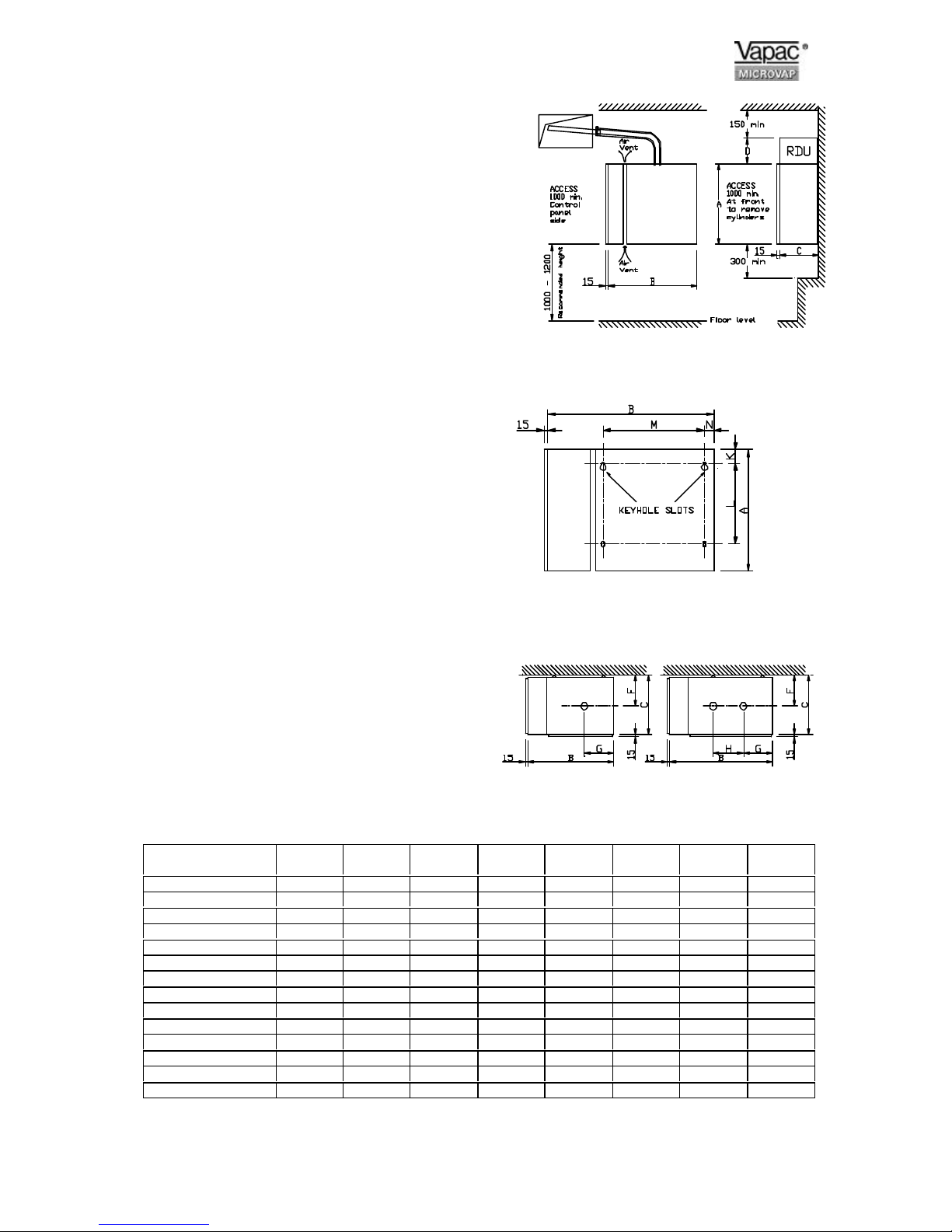
Do mount the unit as close to the steam distribution pipe(s)
as possible.
Do mount the unit at a height convenient for reading the
display window.
Do ensure adequate side access to the electrical section
(min 1000 mm).
Do ensure adequate service access to the front of the unit
(min 1000 mm).
Do ensure adequate service access below the unit (min 300
mm).
Do ensure that the holes above the airgap between the
electrical and the steam sections remain unobstructed to
allow a free flow of air.
Do use the marking on the side of the carton as a template
to mark the mounting hole positions.
Do remove the cylinder, if necessary, to access the
mounting holes in the back of the steam section.
Do use M6 projecting type wall bolts or equivalent to mount
the unit in position.
Do mount units with RDU’s so that steam pipe discharge is
above head height.
Do leave minimum 150mm between the top of an RDU and
the ceiling.
Don’ts
Don’t mount the unit close to sources of strong electro-
magnetic emissions e.g. variable speed lift motor drives,
kVa transformers etc.
Don’t mount the unit in an unventilated enclosure.
Don’t mount in a position requiring ladder access to the
unit.
Don’t mount the unit behind a false ceiling or other situation
where an unusual malfunction (e.g. water leak) would
cause damage.
Don’t mount the unit in an area which will be hosed down.
Don’t install the unit where the ambient temperature can
exceed 35oC.
Don’t mount the unit inside a cold-room or other place
where temperature and humidity conditions can cause
condensation on electrical components.
Don’t mount the unit where the sound of a contactor
opening/closing and water flow in a pipe would be
unacceptable e.g. libraries, private apartments, etc.
Don’t position an RDU to discharge directly over
exspensive equipment, desks or stored materials.
Dimensions in mm and Service Weight in Kg.
Positioning and Dimensions of the Vapac
Fig 1
Mounting Hole Positions.
Fig 2
Steam Outlet Positions
Microvap model V4
VP4
V8
VP8
V15
VP15
V30
VP30
V40
VP40
V40L
VP40L
V60
VL60
V80
VP80
A 500 630 675 800 800 800 800 800
B 380 380 435 538 538 645 645 857
C 263 263 298 384 384 500 500 384
D 182 182 182 - - - - -
F 159 159 175 206 206 266 266 212
G 112 112 136 190 190 195 195 175
H - - - - - 110 110 350
K 38 38 38 38 38 38 38 38
L 478 478 516 643 643 643 643 643
M 165 165 203 305 305 406 406 610
N 38 38 38 47 47 47 47 47
UNIT Kg. 25 25 30 55 55 90 90 97
RDU Kg. 8 8 12 - - - - -
RDU & Transformer 9.5 9.5 16.5 - - - - -
Fig 3
Page 4

4
Steam Pipe Positioning
* Ø 35mm steam pipe : non-standard pipe required which has reverse slope and end outlet Ø15mm.
Pipe in-duct length 300mm – Pt No. M520115, 450mm – Pt. No. M520116, 600mm – Pt. No. M520117, 750mm – Pt. No.
M520118, 900mm – Pt. No. M520119, 1050 mm – Pt. No. M520120.
* Ø 54mm steam pipe : non-standard pipe required which has reverse slope and end outlet Ø15mm.
Pipe in-duct length 650mm - Pt No. M520078
Pipe in-duct length 900mm - Pt. No. M520079
Pipe in-duct length 1400mm - Pt.No. M520080
Notes:-
1 Steam pipe to have a
minimum slope from the
horizontal of 7° or 12% to
allow the condensate to drain
back to cylinder or trap.
NO HORIZONTAL RUNS.
NO 90° ELBOWS.
2 Water condensate to slope at
10° or 18% from horizontal for
condensate to drain back to
drain point.
3 Steam pipes horizontal
mounted must discharge
vertically upward.
Notes Con’t :-
Vertical mounted steam pipe must
discharge horizontally facing
upstream airflow.
5 If the total pressure within the duct
air flow exceeds 2000 Pa and the
static pressure is below 2000 Pa
then the probe may face horizontally
at right angles to the air stream.
Key :-
1 Insulated Steam Pipe
2 Steam Distribution Pipe
3 Hose clip
4 Condensate Separator
Air
Vent
Air
Vent
X = 60 minimum height for a maximum negative
pressure of –600 Pa.
Y = 220 minimum height for a maximum positive
pressure of 2000 Pa.
Z = 250 minimum Radius for 35 ∅ pipe,
500 minimum Radius for 54 ∅ pipe.
35 ∅ 1 Steam Pipe 35 ∅ 1 Steam Pipe 35 ∅ 2 Steam Pipes
35 ∅ or 54 ∅
1 Steam pipe
54 ∅ 1 Steam Pipe 54 ∅ 2 Steam Pipes 54 ∅ 2 Steam Pipe
35 ∅ or 54 ∅
2 Steam Pipes
DUCT MOUNTING DETAIL
FOR 35 ∅ Steam Pipe
3 x 5.0 ∅
Fixing
Holes on
120 PCD.
DUCT MOUNTING DETAILS
FOR 54 ∅ Steam Pipe
4 x 6.4 ∅ Fixing Holes on
170 PCD.
FLOOR LEVEL
Fig 4
Fig 5
Page 5

5
Positioning the steam pipes
General
Steam pipes should be positioned as shown below,
allowing a minimum rate of fall back to the unit of
12% to allow the free flow of condensate back to the
unit. If the above fall is not possible, then
condensate separators must be fitted as shown in
figure 1.
The position of the steam pipe or multipipe in a airconditioning system relative to other items such as
bends, filters, heat exchangers, etc., is critical. The
steam pipe must not be located closer to such item,
than the entrainment distance, and must be decided
by the design engineer responsible for the project.
Do's
Do obtain project engineer's instruction/drawing for
chosen location of pipe
Do obtain project engineer's instruction/drawing for
pipe position relative to the top & bottom of the
duct (or sides if airflow is vertical).
Do check if alternative slope of Ø35mm pipe has
been specified requiring rotation of pipe in its
socket before installation.
Do use bracket/lug on the end of Ø54mm pipes for
extra support.
Steam Hose Connection
Do's
Do use Vapac steam hose or well insulated copper
pipe.
Do keep steam hose as short as possible (under 2m
for max efficiency).
Do arrange to have a vertical rise immediately over
the unit of 300mm.
Do use the full height available between the unit
and steam pipe to provide maximum slope (min
12-20% for condensate
to drain back to the steam cylinder (or down to a
condensate separator). Always provide a
continuous slope.
Do provide adequate support to prevent sagging
a) fit pipe clips every 30-50cm
or b) support straight lengths on cable trays
or in heat resistant plastic pipe.
Do ensure radius hose bends are fully supported to
prevent kinks developing when in service.
Do add extra insulation to steam hose for longer
runs (2m-5m) and in cold ambient conditions to
avoid excess condensate and reduction in
delivered output.
Don'ts
Don't allow steam hose to develop kinks or sags.
Don't include horizontal runs or 90o elbows in the
steam line.
Steam Distribution Pipe requirement
Microvap Model V4
V8
V15
VP4
VP8
VP15
V30
V40
VP30
VP40
V60
V80
VP60
VP80
35mm ∅ Pipe No.
54mm ∅. Pipe No.
1
-
-
1
-
2
* Duct Pressure Pa. +1000
-600
+2000
-600
* For systems with a duct pressure over +1000 Pa. It may
be necessary to fit a suitably sized trap in the water feed
line between the Vapac tundish and the feed drain
manifold to ensure water can enter the cylinder when it is
empty.
35mm ∅ Pipe Selection 54mm ∅ Pipe Selection
Duct width
B mm
In-duct Length
L mm
Duct width
B mm
In-duct Length
L mm
320-470
470-620
620-770
770-920
920-1070
1070-1200
300
450
600
750
900
1050
700-950
950-1450
1450+
(Kg)
650 (1.8)
900 (2.2)
1400 (3.2)
R min for 35 ∅ Pipe = 250mm
R min for 54 ∅ Pipe = 500mm
Flexible Steam
Pipe.
No Sags!
Distance to first
bend.
VAPAC
HUMIDIFIER
Flexible Steam
Pipe.
Flexible pipe coupling to
connect Steam pipe to Duct
pipe coupling length to allow
for line movement and
expansion. Coupling clamp
with Hose clips each end.
35 or 54 mm
copper or
stainless steel
steam pipe with
Fig 6
Page 6

6
Plumbing Considerations.
Cold water supply.
General
The Electrode Boiler range of units is capable of
operating with a range of water quality raw mains.
The water supply should be within the following
limits:-
Hardness 50 –500 ppm
Conductivity 80 – 1000 µµS/cm
Silica 0
Pressure of between 1 - 8 bar.
Water Supply rates
1.2 l/min V4
V8
V15
VP4
VP8
VP15
2.5 l/min V40
V30
V60
VP40
VP30
VP60
5.0 l/min V80 VP80
Do’s
Do install a stop-valve/Shut-off valve and a strainer
close to the unit.
Do provide a water supply with sufficient pressure
and pipe size to ensure an adequate flow rate to
all units connected to the system.
Do use the water connection with nylon nut
provided.
ALL Dimensions in mm
Don'ts
Don’t use a wrench or other tool to tighten the water
supply connection - the nylon nut and rubber
washer provided, should only require tightening
by hand to effect a seal. If water seepage occurs,
undo the nut to wipe the washer clean and reseat it.
Drain connection.
General
Do's
Do ensure metal drain and supply water pipework is
grounded electrically close to the unit (a
ground/earth stud is positioned on the underside
of the cabinet).
Drain capacity per cylinder
= pump discharge rate of max 16.8 l/min at 50 Hz.
Power supply 17.2 l/min at 60 Hz.
Do’s
Do use copper or plastic pipe rated for 100 oC.
Do arrange to discharge drain water from the unit
into a trapped and vented drain at a position
where flash steam rising from the drain line vent
will not pose a problem for the Vapac or other
equipment.
Do provide adequate fall for the drain pipework to
alow free flow of water drained from each unit.
Do ensure drain line pipe size will accommodate
water being drained at the same time from all the
Vapac units which are connected to it.
Microvap Model V4
VP4
V8
VP8
V15
VP15
V30
VP30
V40
VP40
V40-L
VP40-L
V60
V60
V80
VP80
A
B
C
D
58
200
-
-
58
200
-
-
79
198
-
-
133
248
-
-
133
248
-
-
193
312
-
-
193
312
-
-
118
237
468
587
A
B
C
D
E
K
L
M
N
F
G
H S V
KEY: -
A Tundish Fill-cup
B Steam Cylinder
C Feed Drain Manifold
D Drain Pump
E Drain Trap Dish
F Feed Solenoid Valve
G Water Connection ” BSP.
H Flexible hose ” BSP.
K 35∅ Steam Hose coupling and Hose
Clips.
L 35∅ copper or plastic Drain for 110°C
Water with supports.
M Tundish
N U-trap side exit.
S Optional Strainer
V Isolation stop cock
V & VP size 4 - 60
V & VP 80
Fig 7
Page 7

7
Electrical Connections
Important E.M.C. Considerations
Use a dedicated, earthed metal conduit for both the
control signal cable and the security circuit cables
along their entire length - they may share the same
conduit where practicable. The earth must be made
by "metal-to-metal" contact and should be a good
RF (Radio Frequency) earth.
The control and security circuit connections should
be run in screened cable with the screen grounded
at the Microvap end (onto the electrical section back
panel). The screen should be maintained as close
as possible to the cable ends and any tail between
the screen and the earth point must be kept short
(50 mm maximum).
Control Cable / Security Circuit
Conduit Entry Arrangement
Control Cable / Security Circuit
Screening Arrangement
Tail to be kept short
(less than 50mm)
Cables to control terminals
Screen left intact
Outer insulation
Earthed back panel
Important Power Connection Information
Vapac 24V secondary Transformer Primary supply connections:
Vapac units are wired to allow connection to alternative site Voltages.
Make the following simple checks before connecting the power supply:Move the RED connection on the Microvap transformer primary winding
circuit to the position marked with the supply Voltage that is to be connected
between Microvap power terminals A1 and A2.
The transformer primary circuit terminal positions are clearly marked:- 200V,
230V, 380, 415 & 440V. For sites where the actual (measured) voltage is
400V the preferred transformer tapping is 380V.
Note:
24 V a.c. Control circuit -
Transformer Primary Circuit And RDU.
230V ac Pump Supply. -
3.15 A 20 mm (F - Quick blow) fuse (Pt.No. 1080096) mounted on Terminal
rail F3 for master control and F4 for slave unit control.
Two fuses protect the control circuit on Single cylinder units F1 2.0A (slow
blow) (Pt. No. 1080095) mounted in fuse-terminal holder protects Primary
transformer and RDU unit if fitted. F2 500 mA 20 mm (F - Quick blow) fuse (Pt
No. 1080054) mounted in fuse-terminal holder protects Transformer Primary
and Pump or both pumps if two pumps are fitted. Twin cylinder units F5 2.0A
(slow blow) (Pt. No. 1080095) mounted in fuse-terminal holder protects second
RDU unit if fitted.
The pump or pumps on twin cylinder units are feed from the main transformer
via a 230 volt auto winding. The pumps are protected by fuse F1 and F2 above
feeding the transformer primary.
All metal surfaces which come
into contact with each other,
must be free of paint, grease,
dirt, etc., thereby ensuring a
good low impedance R.F.
(Radio Frequency) path to
ground.
Electrical section metalwork
Metal conduit
Page 8

8
Power Supply Connection
Electrical Connections
The wiring to the Vapac should be done by a
qualified electrician. The external overcurrent
protection and wiring should comply with the
appropriate Regulations and Codes of Practice.
Important: Make sure the connection to the primary
Voltage winding of the Vapac transformer matches
the supply Voltage which is to be connected
between Vapac terminals A1 & A2.
A fused disconnect/isolator or MCB should be used
to disconnect the supply from all electrodes
simultaneously.
This must be sized to suit the total maximum
phase/line current of the unit and should be located
adjacent to the Vapac cabinet or within easy reach
and readily accessible.
In Vapac Microvap units terminals 1, 2 and 3 are for
the power supply connections as indicated in the
diagrams below.
Twin cylinder models and single cylinder size 40L
and 60L have terminals for the connection of two
power supply input circuits. On twin cylinder units
this allow individual external protection of each
steam cylinder. Fused disconnect/isolator or MCB
provision must be linked to ensure both 3 phase
supply inputs are disconnected simultaneously.
Cable Entry Provision
Cable glands must be used to ensure cables are
held securely at the entry position. All Vapac
cabinets (sizes 1, 2, 3, 4, 5, 6, 7 & 8) are equipped
with a removable gland-plate. The installing
electrician should remove this and take it to a workbench to drill for the required cable gland size.
Vapac Control Circuit Transformer
The internal control circuit of the Vapac unit is
operated at 24Vac - To offset possible Voltage drop
in any external circuit connection, two optional
relays are available. One for the security circuit
which connects across terminals 9 & 10 Pt. No.
1150618 the other is for remote auto stop start
signal which brakes the control signal to terminal 7.
Both relays can be fitted into the microvap unit at
any time and prevent external volt drop interfering
with the 1150601 PCB. Control. As standard the
Vapac Microvap includes a transformer with
alternative primary winding options 200V, 230, 380,
415, and 440V and requires on site adjustment to
match it to the Voltage connected to Vapac
terminals A1 and A2.
The transformer 8V secondary supply is not used.
Important: The Vapac transformer must NOT be
used to power other equipment or the warranty will
be invalidated.
RDU Connection
Vapac terminals 25 & 26 and 27 & 28 are included
to provide a 230Vac electrical supply for the fan
motor in the RDU (Room Distribution Unit ) .
Note: The 230Vac at terminals is derived from the
incoming electrical supply to the Vapac. If the local
supply cannot provide 230Vac (example 400V No
Neutral supply) it will be necessary for a transformer
to be fitted in the RDU as indicated below.
FOR FULL ELECTRO-MAGNETIC COMPATIBILITY A NEUTRAL CONNECTION IS REQUIRED FOR ALL
VP UNITS AS INDICATED IN THE CONNECTION DIAGRAMS ON THE FOLLOWING PAGES.
RDU Connection
The three type’s of RDU are for various voltages and phase without neutrals connections that can be made to the Microvap unit. Please
refer to the Microvap connection diagram on the following two pages as to which type of unit is required. On twin cylinder units two fan
circuits as shown below one for each cylinder will be in the RDU unit.
Notes:-
1. All units must have a PE earth connection connected to the units terminal.
2. Unit with N.A. in the following tables means NOT AVAILABLE there is not a unit available to run at the voltage
and phases shown. Please check that the correct model reference is ordered and installed, for the low or high
voltage required, and at the desired steam output.
3. These tables give the maximum capacities for each unit at the different voltages. Lower outputs can be provided
using "Output Reduction in the Adjust Menu.
4. Standard design is for 50 Hz. Supplies. Design for 60 Hz. Also available - 60 Hz. Supply must be specified with
order as standard pump is only 50Hz.
5. If a maximum KW has been strictly specified which is less than the maximum in the Electrical Data, this must be
specified with order as an alternative Current Set Plug (CSP) will be needed. This is subject to the agreement of
the manufacturer.
6. For other Voltage electrical supplies, contact the Vapac distributor.
200 – 250 V 1Ph. N + earth 200 – 250 V 2Ph. + earth
380 – 440 V 2Ph. + earth
TRANSFORMER
PRIMARY
380 – 440 V
SECONDARY
210 – 250 V
Page 9

9
 Loading...