

Page 1

These instructions contain operating information and should be left with the unit.
Electrode Boiler Units
LE
Installation & Operation Manual
Edition 3.2.2
(For use with Software version 7.1 & subsequent issues)
Installation in countries covered by EC Directives:
This product meets the requirements of the RoHS Directive 2002/95/EEC
This product will meet the requirements of the Low Voltage Safety Directive
Directive
2004/108/
Failure to comply with these instructions may invalidate the manufacturer's warranty or any
certificate/declaration of conformance requested to be supplied with the unit.
EEC when installed in accordance with the instructions contained in this manual.
2006/95/
EEC and the EMC
Page 2

2
CONTENTS
Important Installation Points .................................................................................................................... 3
1.0 Installation. .................................................................................................................................... 4
1.1 Vapac LE unit dimensions ......................................................................................................... 4
1.1.1 LE weights ............................................................................................................................. 8
1.2 Positioning the steam pipes ...................................................................................................... 8
1.2.1 General .................................................................................................................................. 8
1.2.2 Steam Hose Connection ........................................................................................................ 8
1.3 Plumbing Considerations. ......................................................................................................... 9
1.4 Electrical Connections ............................................................................................................. 10
1.4.1 Important E.M.C. Considerations ....................................................................................... 10
1.4.2 Power Supply Connection ................................................................................................... 11
1.4.2.1 Volt free alarm outputs ........................................................................................................ 11
1.4.2.2 Unit control terminals ........................................................................................................... 11
1.4.3 Electrical Connections ......................................................................................................... 12
1.4.4 Cable Entry Provision .......................................................................................................... 12
1.4.5 Vapac Control Circuit Transformer ...................................................................................... 12
1.4.6 RDU Connection .................................................................................................................. 12
1.5 Cylinder Electrical demand loads ............................................................................................ 14
1.5.1 LExx Units............................................................................................................................ 14
1.5.2 LExxP Units ......................................................................................................................... 17
1.6 Control Circuit Connections .................................................................................................... 19
1.6.1 Control Circuit Wiring ........................................................................................................... 19
1.6.2 Proportional Control ............................................................................................................. 19
1.6.3 Control Signal Selection ...................................................................................................... 19
1.6.4 On/Off Control ..................................................................................................................... 19
1.6.5 Sensing Head ...................................................................................................................... 20
1.6.6 Security Circuit / E.P.O. Shutdown ...................................................................................... 20
1.6.7 Load Shed Option ................................................................................................................ 20
1.6.8 Master/Slave System ........................................................................................................... 21
2.0 Start-Up / Operation .................................................................................................................... 22
2.0.1 Start-up check list ................................................................................................................ 22
2.0.2 Start-Up Instructions ............................................................................................................ 22
2.0.3 Commissioning/Start-Up ...................................................................................................... 22
2.0.4 Features of VAPANET Electode Boiler Unit ........................................................................ 22
2.1 Service Advice......................................................................................................................... 23
2.1.1 Procedure for cylinder Exchange. ....................................................................................... 23
2.1.2 Typical Cylinder / Electrode Layouts ................................................................................... 23
2.2.1 Feed Valve with Strainer ..................................................................................................... 24
2.2.2 Drain Pump .......................................................................................................................... 24
3.0 Location of Indicators and Controls ............................................................................................ 25
3.1 Positioning of Indicators and controls on Vapac ® Vapanet ® LE Units. ............................... 25
3.2 Initial Set-up ............................................................................................................................ 26
3.3 Normal Run / Standby / Start-up – No User Intervention Required ........................................ 27
3.4 Fault / Service Indications – Requiring Operator Intervention. ............................................... 28
3.4.1 To Postpone the Sevice: ..................................................................................................... 28
3.4.2 To Service the unit: .............................................................................................................. 29
3.5 Fascia Label symbols .............................................................................................................. 30
3.6 Other Options .......................................................................................................................... 30
4.0 Trouble-shooting Check List ....................................................................................................... 31
5.0 Wiring diagram ............................................................................................................................ 32
Appendix 1. ............................................................................................................................................ 43
A Guide to Positioning Steam Pipes: ................................................................................................. 43
Appendix 2 ............................................................................................................................................. 45
A Guide to Positioning Multipipes: ..................................................................................................... 45
Page 3

3
Important Installation Points
The unit must be installed to comply with national regulations and/or codes of practice. A qualified
electrician must carry this out.
Ensure at least 1000 mm clear front access to the electrical and steam sections.
Do not locate the cabinet where the ambient temperature around the unit could exceed 35º C; or
fall below 5º C e.g., an unventilated roof mounted enclosure – see minimum space / ventilation
requirements page 7. * If below 5º C Frost protection kit required.
Do not locate the cabinet where a ladder is required for service access as this could make
servicing and cylinder service or exchange hazardous.
Make sure steam line(s) have adequate slope (min 12%) for condensate drainage and use
condensate separators if the pipe is lower than the unit.
Provide adequate support to prevent sags developing in flexible steam lines, which can fill with
water and create a "trap".
Do not locate vented drain directly under the cabinet.
Important Electrical Connection Items
Control cabling should be run in screened cables and kept separate from any mains carrying
cables (see page 10).
Before commissioning the unit, check that all electrical (power) connections - including those at
the terminals and contactor are tight.
Check that the transformer primary winding connection is correct for the supply voltage at Vapac
terminals A1 & A2.
The Vapac transformer must not be used to power other equipment.
Do not mount the 'LR' unit close to a source of strong electromagnetic emissions, such as a
variable speed motor drive, Kva transformer, or 'UPS' unit.
A minimum gap of 2 meters must be maintained between the unit and such devices.
Larger output devices may require an increased gap distance, depending on the nature of
screening / filtration measures fitted to the device.
Use a high-limit humidistat to ensure positive interruption of unit operation when overhumidification is detected (See page 17).
It is important that the control signal connected to terminals 5 & 6 must be referenced to ground at
the control PCB – this can be done by linking either terminal 5 or 6 to terminal 7.
NB if the controller output is referenced to ground, it is important that the “leg” which is
connected to ground at the controller is also connected to ground at the Vapac unit. Grounding
the opposite “leg” will cause damage to the controller and/or the Vapac control PCB.
Important Maintenance Items
Only a qualified electrician should carry out maintenance.
The boiler contains hot water, and must be drained before any maintenance is carried out on the
steam section. This should be done prior to isolating the power, and removing the front access
panel
ESD SENSITIVE DEVICES USED ON PCB. ENSURE ANTI-STATIC PRECAUTIONS ARE TAKEN
WHEN REMOVING OR REPLACING PCB’S.
Page 4

Cabinet Size 1.
LE18
–
All
points.
1.0 Installation.
Do’s
Do mount the unit as close to the steam distribution
pipe(s) as possible.
Do mount the unit at a height convenient for reading the
display window.
Do ensure adequate side ventilation (min 80 mm).
Do ensure adequate service access to the front of the unit
(min 1000 mm).
Do ensure adequate service access below the unit (min
1000 mm).
Do ensure that the holes in the rear top panel remain
unobstructed to allow a free flow of air see fig 1.
Do use the marking on the side of the carton as a template
to mark the mounting hole positions.
Do remove the cylinder, if necessary, to access the
mounting holes in the back of the steam section.
Do use M6 projecting type wall bolts or equivalent to
mount the unit in position.
Do mount units with RDU’s so that steam pipe discharge is
above head height.
Do leave minimum gap between the top of an RDU and
the ceiling as per table in fig 2.
1.1 Vapac LE unit dimensions
Covering model references:
LE05 – All
LE09 – All
6.0265.055.0
4
Don’ts
Don’t mount the unit close to sources of strong electro-
magnetic emissions e.g. variable speed lift motor
drives, kVa transformers etc.
Don’t mount the unit in an unventilated enclosure.
Don’t mount in a position requiring ladder access to the
unit.
Don’t mount the unit behind a false ceiling or other
situation where an unusual malfunction (e.g. water
leak) would cause damage.
Don’t mount the unit in an area which will be hosed down.
Don’t install the unit where the ambient temperature can
exceed 35oC; or fall below 5oC (Unless frost protection
kit fitted).
Don’t mount the unit inside a cold-room or other place
where temperature and humidity conditions can cause
condensation on electrical components.
Don’t mount the unit where the sound of a contactor
opening/closing and water flow in a pipe would be
unacceptable e.g. libraries, private apartments, etc.
Don’t position an RDU to discharge directly over
expensive equipment, desks or stored materials
203.0172.0
6.0
Left:
Top view of unit
showing steam outlet
position (35 mm spigot)
Below:
Rear view of unit
showing wall mounting
.
Right:
View from beneath unit
showing the electrical gland
plate (approx 120mm x
120mm) with an entry hole
(approx 105mm x 90mm)
120.0
140.0
675.0
50.0
74.0444.0
Left:
View from beneath unit showing:
‘F’ (Feed) 19mm BSP male
connection for connection for
flexible hose provided with unit.
‘D’ (Drain) connection for 35 mm
pipe.
172.0203.0
285.0
430.0
70.0
F
D
204.0
For clearance around the unit for ventilation & access please see page 7
Page 5

Cabinet Size 2.
LE55
-
All
Covering model references:
LE30 – All
LE45 – All
6
360
55
165
330
305
5
6
186
Steam Outlet 54 mm
Left:
Top view of unit showing
steam outlet position
(54 mm spigot)
Below:
Rear view of unit showing
wall mounting points.
165
Right:
View from beneath unit
showing the electrical gland
plate
(approx 120 mm x 120 mm)
with an entry hole
(approx 105 mm x 90 mm)
Gland Plate
810
120 X 120
299
62
52
520
73555
305
70
Left:
View from beneath unit
showing-
‘F’ (Feed) ¾ “ BSP male
connection for connection
D
F
90
for flexible hose provided
with unit.
‘D’ (Drain) connection for
35 mm pipe.
For clearance around the unit for ventilation and access and for units with RDU’s see page 7
Page 6

Cabinet Size 4.
Covering model references:
LE60 – All
LE90 – All
LE110 – All
6
360
55
610
190
6
176
346
322
6
55
360
Steam Outlets
54 mm
Left:
Top view of unit showing
steam outlet positions
(54 mm spigots)
Below:
Rear view of unit showing
wall mounting points.
610
990
190
73555
Right:
View from beneath unit showing
the electrical gland plate
(approx 120 mm x 120 mm)
with an entry hole
(approx 105 mm x 90 mm)
Gland Plate
120 X 120
810
20.5"(520)
70 850
F F
152
343
505
31.1"(790)
468
Left:
View from beneath unit
Gland Plate
120 X 120
62
D
237
343
showing-
‘F’ (Feed) ¾ “ BSP male
connection for connection
for flexible hose provided
with unit.
‘D’ (Drain) connection for
35 mm pipe.
For clearance around the unit for ventilation and access see page 7
Page 7

Cabinet Sz 1 with RDU
Cabinet
Clearance around LE Units
LE09 All
LE18 All
LE30 All
LE45/LE55
LE45/55
Dimensions
size 2 with
RDU
Dimensions
RDU 30 kg/h
A = 602mm
B = 205mm
RDU 45 kg/h
A = 842mm
B = 360mm
7
L L
H
H2
H1
Unit L
LE05 All
(No RDU)
LE05 All
(With RDU)
LE09 All
(No RDU)
(With RDU)
(No RDU)
LE18 All
(With RDU)
LE30 All
(No RDU)
(With RDU)
(No RDU)
(With RDU)
LE60 - 110 All (Twin
Cylinder No RDU)
H
min
85 1000 500 -
85 1000 - 200
85 1000 500 -
85 1000 - 250
85 1000 500 -
85 1000 - 500
85 1000 500 -
100 1000 - 750
85 1000 500 -
200 1000 - 775
85 1000 500 -
H1
min
H2
min
A minimum clear space of 1 m is required in
front of the unit for maintenance access
Page 8

∅
For guidance on positioning of steam pipes see Appendix 1.
8
1.1.1 LE weights
The unit dry weight is the delivered unit with no
water in unit, the wet weight is the operational
weight when the unit is running . The RDU
weight must be added to the unit weight if fitted
on top of the Electrode Boiler unit.
Vapanet model Dry Kg Wet Kg RDU
Kg
LE05 and LE05P 23.5 29 6
LE09 and LE09P 24 31 10
LE18 and LE18P 24.5 36 12
LE30 and LE30P 34 62 14
LE45,LE45P & LE55 34 62 16
LE60 and LE60P 52 106 NA
LE90, LE90P & LE110 52 106 NA
1.2 Positioning the steam pipes
1.2.1 General
Steam pipes should be positioned as shown below,
allowing a minimum rate of fall back to the unit of
Do ensure radius hose bends are fully supported to
prevent kinks developing when in service.
Do add extra insulation to steam hose for longer
runs (2m-5m) and in cold ambient conditions to
avoid excess condensate and reduction in
delivered output.
Don'ts
Don't allow steam hose to develop kinks or sags.
Don't include horizontal runs or 90o elbows in the
steam line.
Steam Distribution Pipe requirement
Electrode
Boiler Unit
Model
35mm ∅
Pipe No.
54mm ∅.
Pipe No.
Duct
Pressure
Pa.
LE05(P)
LE09(P)
LE18(P)
1
-
+2000
-600
LE30(P)
LE45(P)
LE55
-
1
LE60(P)
LE90(P)
LE110
-
2
+2000
-600
12% to allow the free flow of condensate back to the
unit. If the above fall is not possible, then
condensate separators must be fitted as shown in
appendix 1.
The position of the steam pipe or multipipe in a air-
No Sags!
Flexible Steam
Pipe.
conditioning system relative to other items such as
bends, filters, heat exchangers, etc., is critical. The
steam pipe must not be located closer to such item,
than the entrainment distance, and must be decided
by the design engineer responsible for the project.
Do's
Do obtain project engineer's instruction/drawing for
chosen location of pipe
Flexible Steam
Pipe.
Distance to first
bend.
Do obtain project engineer's instruction/drawing for
pipe position relative to the top & bottom of the
duct (or sides if airflow is vertical.
R min for 35
R min for 54 ∅ Pipe = 500mm
Pipe = 250mm
Do check if alternative slope of Ø35mm pipe has
been specified.
Do use bracket/lug on the end of Ø54mm pipes for
extra support.
VAPAC
HUMIDIFIER
1.2.2 Steam Hose Connection
Do's
Do use Vapac steam hose or well insulated copper
pipe.
Do keep steam hose as short as possible (under 2m
for max efficiency).
Do arrange to have a vertical rise immediately over
the unit of 300mm.
Do use the full height available between the unit
and steam pipe to provide maximum slope (min
12-20% for condensate to drain back to the
steam cylinder (or down to a condensate
separator). Always provide a continuous slope.
Do provide adequate support to prevent sagging
a) fit pipe clips every 30-50cm
or b) support straight lengths on cable trays
35 or 54 mm
copper or
stainless steel
steam pipe with
Insulation.
35mm ∅ Pipe Selection
Duct width
B mm
320-470
470-620
620-770
770-920
920-1070
1070-1200
In-duct Length
L mm
300
450
600
750
900
1050
Flexible pipe coupling to
connect Steam pipe to Duct
pipe coupling length to allow
for line movement and
expansion. Coupling clamp
with Hose clips each end.
Fig 6
54mm ∅ Pipe Selection
Duct width
B mm
700-950
950-1450
1450+
In-duct Length
L mm
(Kg)
650 (1.8)
900 (2.2)
1400 (3.2)
or in heat resistant plastic pipe.
For guidance on use of Multipipes see Appendix 2.
Page 9

9
1.3 Plumbing Considerations.
1.3.1 Cold water supply
General
The Vapanet range of electrode boilers is capable of
operating with a range of “raw mains” water quality. The water
supply should be within the following limits:-
.
Hardness 50 – 500 ppm
Conductivity 80 – 1000µS
PH 7.3 – 8.0
Silica 0
Pressure of between 1 - 8 bar.
In addition, if stainless steel electrodes are used the chlorine
level must not exceed 170 ppm.
Water Supply rates
1.20 l/min
1.20 l/min
1.20 l/min
2.50 l/min
2.50 l/min
5.00 l/min
5.00 l/min
Do’s
Do install a stop-valve/Shut-off valve and a strainer close to
the unit.
Do provide a water supply with sufficient pressure and pipe
size to ensure an adequate flow rate to all units connected
to the system.
Do use the water connection with nylon nut provided.
LE05
LE09
LE18
LE30
LE45/LE55
LE60
LE90/LE110
LE05P
LE09P
LE18P
LE30P
LE45P
LE60P
LE90P
A
B
C
D
F
K
L
M
N
H
G S V
Single Cylinder Units 30-55 kg/h
ALL Dimensions in mm
Don'ts
Don’t use a wrench or other tool to tighten the water supply
connection - the nylon nut and rubber washer provided,
should only require tightening by hand to effect a seal. If
water seepage occurs, undo the nut to wipe the washer
clean and re-seat it.
1.3.2 Drain connection
General
Do's
Do ensure metal drain and supply water pipework is grounded
electrically close to the unit (a ground/earth stud is
positioned on the underside of the cabinet.
Drain capacity per cylinder.
(Max.pump flow rate
at Power supply frequency)
Do’s
Do use copper or plastic pipe rated for 110 oC.
Do arrange to discharge drain water from the unit into a
trapped and vented drain at a position where flash steam
rising from the drain line vent will not pose a problem for
the Vapac or other equipment.
Do provide adequate fall for the drain pipework to allow free
flow of water drained from each unit.
Do ensure drain line pipe size will accommodate water being
drained at the same time from all the Vapac units which
are connected to it.
KEY: -
A Tundish Fill-cup
B Steam Cylinder
C Feed Drain Manifold
D Drain Pump
F Feed Solenoid Valve
G Water Connection ¾” BSP.
H Flexible hose ¾” BSP.
K 35∅ Steam Hose coupling and Hose
L 35∅ copper or plastic Drain for 110°C
M Tundish
N U-trap side exit.
S Optional Strainer
V Isolation stop cock
Clips.
Water with supports.
.
l/min Hz
16.8
17.2
50
60.
Twin Cylinder units 60-110 kg/h
Fig 7
Page 10

Control Cable / Security Circuit
Important Power Connection Information
Note:
1.4 Electrical Connections
10
24 V a.c. Control circuit -
9 V a.c. PCB Circuit -
Transformer Primary Circuit And RDU.
230V ac Pump Supply. -
Vapac 24V and 9 V secondary Transformer Primary supply connections:
Vapac units are wired to allow connection to alternative site Voltages.
Make the following simple checks before connecting the power supply:Move the BROWN connection on the VAPANET transformer primary winding circuit to
the position marked with the supply Voltage that is to be connected between
VAPANET power terminals A1 and A2.
The transformer primary circuit terminal positions are clearly marked:- 200V, 230V,
380, 415 & 440V. If the actual (measured) site voltage is 400v the preferred
tapping is 380V. The transformer is fitted below the Drain tray, and is accessible by
removing two screws and the cover, which should be slid it towards you.
6.3 A 20 mm (T – Time Lag) fuse (Pt.No. 1080093) mounted on VAPANET
Echelon PCB (Pt.No.1150630).
2 A 20 mm (F - Quick blow) fuse (Pt No. 1080099) mounted on the VAPANET
Echelon PCB (Pt, No. 1150630).
Two fuses protect the control circuit on Single cylinder units F1 2.0A (slow
blow) (Pt. No. 1080095) mounted in fuse-terminal holder protects Primary
transformer and RDU unit if fitted. F2 500 mA 20 mm (F - Quick blow) fuse (Pt
No. 1080054) mounted in fuse-terminal holder protects Transformer Primary
and Pump or both pumps if two pumps are fitted.
The pump or pumps on twin cylinder units are fed from the main transformer
via a 230 volt auto winding. The pumps are protected by fuse F1 and F2 above
feeding the transformer primary.
1.4.1 Important E.M.C. Considerations
Use a dedicated, earthed metal conduit for both the control
signal cable and the security circuit cables along their entire
length - they may share the same conduit where practicable.
The earth must be made by "metal-to-metal" contact and
should be a good RF (Radio Frequency) earth.
The control and security circuit connections should be run in
screened cable with the screen grounded at the VAPANET
end (onto the electrical section back panel). The screen
should be maintained as close as possible to the cable ends
and any tail between the screen and the earth point must be
kept short (50 mm maximum).
Control Cable / Security Circuit
Conduit Entry Arrangement
Electrical section metalwork
All metal surfaces which come
into contact with each other,
must be free of paint, grease,
dirt, etc., thereby ensuring a
good low impedance R.F.
(Radio Frequency) path to
ground.
Metal conduit
Cables to control terminals
Outer insulation
Screening Arrangement
Tail to be kept short
(less than 50mm)
Screen left intact
Earthed back panel
Page 11

11
1.4.2 Power Supply Connection
The unit requires the following connections as shown in the
diagram below
1.4.2.1 Volt free alarm outputs
The unit has connections for volt free alarm outputs these are on
the three double terminals next to the main power input terminals.
The top terminals are for unit volt free fault alarm as follows:
The bottom terminals are for unit volt free run signal as follows:
542 common for fault alarm
543 Normally closed when no fault
544 Normally open when no fault
545 Common for run signal
546 Normally closed when unit is in standby or
fault (not running)
547 Normally open when unit is in standby or fault
(not running)
If the unit is part of a master slave system or network, the
run & fault outputs can be selected (via keypad & display)
as either network (system) or unit only. This is selectable at
Service Engineers Level, in the Engineering Menu, in the
window “Fault/Run Scope”. The default is “network”. It is
possible to get both alarm & Run indication in all units:
Single cylinder units will give this indication if the service
interval has expired; Twin Cylinder & Networked units will
give this indication if the service interval has expired or if
the master cylinder is operating and any slave cylinder (or
cylinders) are in fault.
1.4.2.2 Unit control terminals
For unit control and network termination see section
1.6 the terminal layout is shown here.
Page 12

Notes:
-
FOR FULL EL
ECTRO
-
MAGNETIC COMPATIBILITY A NEUTRAL CONNECTION IS REQUIRED FOR ALL PROPORTIONAL
12
1.4.3 Electrical Connections
The wiring to the Vapac should be done by a qualified
electrician. The external overcurrent protection and wiring
should comply with the appropriate Regulations and Codes
of Practice
Important: Make sure the connection to the primary
Voltage winding of the Vapac transformer matches the
supply Voltage which is to be connected between Vapac
terminals A1 & A2.If the actual (measured) site voltage is
400v the preferred tapping is 380V
A fused disconnect/isolator or MCB should be used to
disconnect the supply from all electrodes simultaneously.
This must be sized to suit the total maximum phase/line
current of the unit and should be located adjacent to the
Vapac cabinet or within easy reach and readily accessible.
In Vapac VAPANET units terminals A1, A2 and A3 are for
the power supply connections as indicated in the diagrams
below (twin cylinder units have two supplies A1,A2,A3 &
B1,B2,B3).
Twin cylinder units’ have terminals for the connection of
two power supply input circuits. On twin cylinder units’ this
allows individual external protection of each steam cylinder.
Fused disconnect/isolator or MCB provision must be linked
to ensure both 3 phase supply inputs are disconnected
simultaneously.
.
1. All units must have a PE earth connection connected to the units terminal.
2. Unit with N.A. in the following tables means NOT AVAILABLE there is not a unit available to run at the voltage
and phases shown. Please check that the correct model reference is ordered and installed, for the low or high
voltage required, and at the desired steam output.
3. Standard design is for 50 Hz. Supplies. Design for 60 Hz. Also available - 60 Hz. Supply must be specified with
order as the standard pump is only 50Hz.
1.4.4 Cable Entry Provision
Cable glands must be used to ensure cables are held
securely at the entry position. All Vapac cabinets are
equipped with a removable gland-plate. The installing
electrician should remove this and take it to a workbench to drill for the required cable gland size.
1.4.5 Vapac Control Circuit Transformer
The internal control circuit of the Vapac unit operates at
24Vac - the transformer secondary is set at 24V.
.
As standard the Vapac VAPANET includes a
transformer with alternative primary winding options
200V, 230, 380, 415, and 440V and requires on site
adjustment to match it to the Voltage connected to
Vapac terminals A1 and A2.
The transformer also has a 9V secondary tapping which
provides power to the VAPANET 1150630 PCB.
Important: The Vapac transformer must NOT be used
to power other equipment or the warranty will be
invalidated.
1.4.6 RDU Connection
Vapac terminals 25 & 26 are included to provide a
230Vac electrical supply for the fan motor in the RDU
(Room Distribution Unit) .
Note: The 230Vac at terminals is derived from the
incoming electrical supply to the Vapac. If the local
supply cannot provide 230Vac (example 400V No
Neutral supply) it will be necessary for a transformer to
be fitted in the RDU as indicated below.
UNITS AS INDICATED IN THE CONNECTION DIAGRAMS ON THE FOLLOWING PAGES.
RDU Connection
The three type’s of RDU are for various voltages and phase without neutrals connections that can be made to the Vapanet unit. Please refer to
the Microvap connection diagram on the following three pages as to which type of unit is required. On twin cylinder units two fan circuits as
shown below one for each cylinder will be in the RDU unit.
RDU electrical loads
Model RDU05LE RDU09LE RDU18LE RDU30L RDU45LE
Number of fans 2 3 3 5 7
Fan voltage 230 v 230 v 230 v 230v 230v
Each fan current 50Hz
RDU total load current 50Hz
(60 Hz)
115 mA
(60 Hz)
225 mA
(105 mA)
(210 mA)
115 mA
345 mA
(105 mA)
(315 mA)
115 mA
345 mA
(105 mA)
(315 mA)
115mA
575mA
(105mA)
(525mA)
115 mA
805 mA
(105 mA)
(735 mA)
Page 13

13
Power connection
Power connection
details for LExx
Units
(Units without Solid
State Relays).
Details for LExxP
Units
(Units fitted with
Solid State Relays)
200 – 250 V 1Ph. N + earth
200 – 250 V 2Ph. + earth
380 – 440 V 2Ph + earth
TRANSFORMER
PRIMARY
380 – 440 V
SECONDARY
210 – 250 V
Page 14

Model Ref.
LE05
LE09
2
Model Ref.
LE05
-3
LE09
-3
2
Model Ref.
LE18
LE30
2
14
1.5 Cylinder Electrical demand loads
1.5.1 LExx Units
Nominal Output Kg/hr 5 5 5 5 5 5 9 9 9 9 9 9
Nominal Output lb/hr 11 11 11 11 11 11 19.8 19.8 19.8 19.8 19.8 19.8
Voltage V 200 230 380 400 415 440 200 230 380 400 415 440
Power input rating Kw 3.71 3.72 3.8 3.81 3.75 3.77 6.76 6.68 6.7 6.86 6.72 6.7
Electrical Supply Ph's Ph+N or
2Ph
No. of electrodes
2 2 2 2 2 2 2 2 2 2 2 2
Full load Current A 19.5 17 10.5 10 9.5 9 35.5 30.5 18.5 18 17 16
Maximum overcurrent A 29.25 25.5 15.75 15 14.25 13.5 53.25 45.75 27.75 27 25.5 24
Fuse Rating/phase A 32 32 20 20 16 16 63 50 32 32 32 32
Supply cable terminals mm
10 10 10 10 10 10 16 16 16 16 16 16
Wiring diagram
Cabinet size
Nominal Output Kg/hr 5 5 5 5 5 5 9 9 9 9 9 9
Nominal Output lb/hr 11 11 11 11 11 11 19.8 19.8 19.8 19.8 19.8 19.8
Voltage V 200 230 380 400 415 440 200 230 380 400 415 440
Power input rating Kw 3.79 3.79 3.76 3.96 3.77 3.99 6.76 6.83 6.9 6.93 6.85 6.9
Electrical Supply Ph's 3Ph 3Ph 3Ph 3Ph 3Ph 3Ph 3Ph 3Ph 3Ph 3Ph 3Ph 3Ph
No. of electrodes
3 3 3 3 3 3 3 3 3 3 3 3
Full load Current A 11.5 10 6 6 5.5 5.5 20.5 18 11 10.5 10 9.5
Maximum overcurrent A 17.25 15 9 9 8.25 8.25 30.75 27 16.5 15.75 15 14.25
Fuse Rating/phase A 25 20 16 16 10 10 32 32 20 20 20 16
Supply cable terminals mm
10 10 10 10 10 10 10 10 10 10 10 10
Wiring diagram
Cabinet size
Ph+N or
2Ph
Ph+N or
2Ph
Ph+N or
2Ph
Ph+N or
2Ph
Ph+N or
2Ph
Ph+N or
2Ph
Ph+N or
2Ph
Ph+N or
2Ph
A4-LZD-559 A4-LZD-559
1 1
A4-LZD-559 A4-LZD-559
1 2
Ph+N or
2Ph
Ph+N or
2Ph
Ph+N or
2Ph
Nominal Output Kg/hr 18 18 18 18 18 18 30 30 30 30 30 30
Nominal Output lb/hr 39.6 39.6 39.6 39.6 39.6 39.6 66 66 66 66 66 66
Voltage V 200 230 380 400 415 440 200 230 380 400 415 440
Power input rating Kw 13.36 13.47 13.48 13.53 13.35 13.43 22.43 22.38 22.25 22.43 22.25 22.5
Electrical Supply Ph's 3Ph 3Ph 3Ph 3Ph 3Ph 3Ph 3Ph 3Ph 3Ph 3Ph 3Ph 3Ph
No. of electrodes
3 3 3 3 3 3 6 6 3 3 3 3
Full load Current A 40.5 35.5 21.5 20.5 19.5 18.5 68 59 35.5 34 32.5 31
Maximum overcurrent A 44.55 39.05 23.65 22.55 21.45 20.35 74.8 64.9 39.05 37.4 35.75 34.1
Fuse Rating/phase A 50 50 32 32 25 25 80 80 50 50 40 40
Supply cable terminals mm
Wiring diagram
Cabinet size
16 16 16 16 16 16 35 35 16 16 16 16
A4-LZD-559 A4-LZD-560 A4-LZD-559
1 2
Page 15
Model Ref.
LE45 LE55
2
Model Ref.
LE60
2
Model Ref.
LE90
2
15
Cylinder
Nominal Output Kg/hr 44 45 45 45 45 45 55 55 55 55 55 55
Nominal Output lb/hr 96.8 99 99 99 99 99 NA NA 121 121 121 121
Voltage V 200 230 380 400 415 440 200 230 380 400 415 440
Power input rating Kw 32.66 33.39 33.85 33.65 33.54 33.39 NA NA 41.37 40.91 41.07 41.37
Electrical Supply Ph's 3Ph 3Ph 3Ph 3Ph 3Ph 3Ph NA NA 3Ph 3Ph 3Ph 3Ph
No. of electrodes
Full load Current A 99 88 54 51 49 46 NA NA 66 62 60 57
Maximum overcurrent A 108.9 96.8 59.4 56.1 53.9 50.6 NA NA 72.6 68.2 66 62.7
Fuse Rating/phase A 125 125 63 63 63 63 NA NA 80 80 80 80
Supply cable terminals mm
Wiring diagram
Cabinet size
Cylinder
Nominal Output Kg/hr 30 30 30 30 30 30 30 30 30 30 30 30
Nominal Output lb/hr 66 66 66 66 66 66 66 66 66 66 66 66
Voltage V 200 200 230 230 380 380 400 400 415 415 440 440
Power input rating Kw 22.43 22.43 22.38 22.38 22.25 22.25 22.43 22.43 22.25 22.25 22.5 22.5
Electrical Supply Ph's 3Ph 3Ph 3Ph 3Ph 3Ph 3Ph 3Ph 3Ph 3Ph 3Ph 3Ph 3Ph
No. of electrodes
Full load Current A 68 68 59 59 35.5 35.5 34 34 32.5 32.5 31 31
Maximum overcurrent A 74.8 74.8 64.9 64.9 39.05 39.05 37.4 37.4 35.75 35.75 34.1 34.1
Fuse Rating/phase A 80 80 80 80 50 50 50 50 40 40 40 40
Supply cable terminals mm
Unit Total F.L.C. A 136 118 71 68 65 62
Wiring diagram
Cabinet size
Cylinder
Nominal Output Kg/hr 44 44 45 45 45 45 45 45 45 45 45 45
Nominal Output lb/hr 96.8 96.8 99 99 99 99 99 99 99 99 99 99
Voltage V 200 200 230 230 380 380 400 400 415 415 440 440
Power input rating Kw 32.66 32.66 33.39 33.39 33.85 33.85 33.65 33.65 33.54 33.54 33.39 33.39
Electrical Supply Ph's 3Ph 3Ph 3Ph 3Ph 3Ph 3Ph 3Ph 3Ph 3Ph 3Ph 3Ph 3Ph
No. of electrodes
Full load Current A 99 99 88 88 54 54 51 51 49 49 46 46
Maximum overcurrent A 108.9 108.9 96.8 96.8 59.4 59.4 56.1 56.1 53.9 53.9 50.6 50.6
Fuse Rating/phase A 125 125 125 125 80 80 60 60 60 60 60 60
Supply cable terminals mm
Unit Total F.L.C. A 198 176 108 102 98 92
Wiring diagram
Cabinet size
1 1 1 1 1 1 1 1 1 1 1 1
6 6 6 6 6 6 NA NA 6 6 6 6
35 35 35 35 35 35 NA NA 35 35 35 35
A4-LZD-560 A4-LZD-560
2 2
1 2 1 2 1 2 1 2 1 2 1 2
6 6 6 6 3 3 3 3 3 3 3 3
35 35 35 35 16 16 16 16 16 16 16 16
A4-LZD-560 A4-LZD-559
4
1 2 1 2 1 2 1 2 1 1 1 1
6 6 6 6 6 6 6 6 6 6 6 6
35 35 35 35 35 35 35 35 35 35 35 35
A4-LZD-560
4
Page 16
Model Ref.
LE110
2
16
Cylinder
Nominal Output Kg/hr 55 55 55 55 55 55 55 55 55 55 55 55
Nominal Output lb/hr 121 121 121 121 121 121 121 121 121 121 121 121
Voltage V 200 200 230 230 380 380 400 400 415 415 440 440
Power input rating Kw N.A. N.A. N.A. N.A. 41.37 41.37 40.91 40.91 41.07 41.07 41.37 41.37
Electrical Supply Ph's N.A. N.A. N.A. N.A. 3Ph 3Ph 3Ph 3Ph 3Ph 3Ph 3Ph 3Ph
No. of electrodes
Full load Current A N.A. N.A. N.A. N.A. 66 66 62 62 60 60 57 57
Maximum overcurrent A N.A. N.A. N.A. N.A. 72.6 72.6 68.2 68.2 66 66 62.7 62.7
Fuse Rating/phase A N.A. N.A. N.A. N.A. 80 80 80 80 80 80 80 80
Supply cable terminals mm
Unit Total F.L.C. A N.A. N.A. N.A. N.A. 132 124 120 114
Wiring diagram A4-LZDCabinet size
1 2 1 2 1 2 1 2 1 2 1 2
N.A. N.A. N.A. N.A. 6 6 6 6 6 6 6 6
N.A. N.A. N.A. N.A. 35 35 35 35 35 35 35 35
560 560 562 560 562 560 562 560 562
4
Page 17
17
Model Ref.
LE05P
LE09P
2
Model Ref.
LE05P
-3
LE09P
-
3
2
Model Ref.
LE18P
LE30P
2
1.5.2 LExxP Units
Nominal Output Kg/hr 5 5 5 5 5 5 9 9 9 9 9 9
Nominal Output lb/hr 11 11 11 11 11 11 19.8 19.8 19.8 19.8 19.8 19.8
Voltage V 200 230 380 400 415 440 200 230 380 400 415 440
Power input rating Kw 3.73 3.71 3.78 3.81 3.78 3.83 6.71 6.76 6.77 6.79 6.7 6.74
Electrical Supply Ph's Ph+N or
2Ph
No. of electrodes
2 2 2 2 2 2 2 2 2 2 2 2
Full load Current A 22.5 19.5 12 11.5 11 10.5 40.5 35.5 21.5 20.5 19.5 18.5
Maximum overcurrent A 33.75 29.25 18 17.25 16.5 15.75 60.75 53.25 32.25 30.75 29.25 27.75
Fuse Rating/phase A 40 32 20 20 20 20 63 63 40 32 32 32
Supply cable terminals mm
10 10 10 10 10 10 16 16 16 16 16 16
Wiring diagram
Cabinet size
Nominal Output Kg/hr 5 5 5 5 5 5 9 9 9 9 9 9
Nominal Output lb/hr 11 11 11 11 11 11 19.8 19.8 19.8 19.8 19.8 19.8
Voltage V 200 230 380 400 415 440 200 230 380 400 415 440
Power input rating Kw 3.73 3.79 3.82 3.73 3.87 3.79 6.74 6.76 6.81 6.89 6.85 6.94
Electrical Supply Ph's 3Ph 3Ph 3Ph 3Ph 3Ph 3Ph 3Ph 3Ph 3Ph 3Ph 3Ph 3Ph
No. of electrodes
3 3 3 3 3 3 3 3 3 3 3 3
Full load Current A 13 11.5 7 6.5 6.5 6 23.5 20.5 12.5 12 11.5 11
Maximum overcurrent A 19.5 17.25 10.5 9.75 9.75 9 35.25 30.75 18.75 18 17.25 16.5
Fuse Rating/phase A 25 20 16 16 16 16 40 32 20 20 20 20
Supply cable terminals mm
10 10 10 10 10 10 10 10 10 10 10 10
Wiring diagram
Cabinet size
Nominal Output Kg/hr 18 18 18 18 18 18 30 30 30 30 30 30
Nominal Output lb/hr 39.6 39.6 39.6 39.6 39.6 39.6 66 66 66 66 66 66
Voltage V 200 230 380 400 415 440 200 230 380 400 415 440
Power input rating Kw 13.34 13.36 13.35 13.48 13.39 13.57 22.38 22.43 22.35 22.38 22.32 22.41
Electrical Supply Ph's 3Ph 3Ph 3Ph 3Ph 3Ph 3Ph 3Ph 3Ph 3Ph 3Ph 3Ph 3Ph
No. of electrodes
3 3 3 3 3 3 6 6 3 3 3 3
Full load Current A 46.5 40.5 24.5 23.5 22.5 21.5 78 68 41 39 37.5 35.5
Maximum overcurrent A 51.15 44.55 26.95 25.85 24.75 23.65 85.8 74.8 45.1 42.9 41.25 39.05
Fuse Rating/phase A 60 50 32 32 32 32 100 100 50 50 50 50
Supply cable terminals mm
16 16 16 16 16 16 35 35 16 16 16 16
Wiring diagram
Cabinet size
Ph+N or
2Ph
Ph+N or
2Ph
Ph+N or
2Ph
Ph+N or
2Ph
Ph+N or
2Ph
Ph+N or
2Ph
Ph+N or
2Ph
Ph+N or
2Ph
Ph+N or
2Ph
A4-LZD-559 A4-LZD-559
1 1
A4-LZD-559 A4-LZD-559
1 1
A4-LZD-559 A4-LZD-561 A4-LZD-559
1 2
Ph+N or
2Ph
Ph+N or
2Ph
Page 18
Model Ref.
LE45P
2
Model Ref.
LE60P
2
Model Ref.
LE90P
2
18
Cylinder
1 1 1 1 1 1
Nominal Output Kg/hr 45 45 45 45 45 45
Nominal Output lb/hr NA NA 99 99 99 99
Voltage V 200 230 380 400 415 440
Power input rating Kw NA NA 33.79 33.85 33.93 33.45
Electrical Supply Ph's NA NA 3Ph 3Ph 3Ph 3Ph
No. of electrodes
NA NA 6 6 6 6
Full load Current A NA NA 62 59 57 53
Maximum overcurrent A NA NA 68.2 64.9 62.7 58.3
Fuse Rating/phase A NA NA 80 80 80 80
Supply cable terminals mm
Wiring diagram
Cabinet size
NA NA 35 35 35 35
A4-LZD-561
2
Cylinder
1 2 1 2 1 2 1 2 1 2 1 2
Nominal Output Kg/hr 30 30 30 30 30 30 30 30 30 30 30 30
Nominal Output lb/hr 66 66 66 66 66 66 66 66 66 66 66 66
Voltage V 200 200 230 230 380 380 400 400 415 415 440 440
Power input rating Kw 22.38 22.43 22.43 22.38 22.35 22.25 22.38 22.43 22.32 22.25 22.41 22.5
Electrical Supply Ph's 3Ph 3Ph 3Ph 3Ph 3Ph 3Ph 3Ph 3Ph 3Ph 3Ph 3Ph 3Ph
No. of electrodes
6 6 6 6 3 3 3 3 3 3 3 3
Full load Current A 78 68 68 59 41 35.5 39 34 37.5 32.5 35.5 31
Maximum overcurrent A 85.8 74.8 74.8 64.9 45.1 39.05 42.9 37.4 41.25 35.75 39.05 34.1
Fuse Rating/phase A 100 100 100 100 50 50 50 50 50 50 50 50
Supply cable terminals mm
35 35 35 35 16 16 16 16 16 16 16 16
Unit Total F.L.C. A 146 127 76.5 73 70 66.5
Wiring diagram
Cabinet size
A4LZD
561 562 561 562 559 562 559 562 -559 562 -559 -562
4
Cylinder
1 2 1 2 1 2 1 2 1 2 1 2
Nominal Output Kg/hr 45 45 45 45 45 45 45 45 45 45 45 45
Nominal Output lb/hr NA NA NA NA 99 99 99 99 99 99 99 99
Voltage V 200 200 230 230 380 380 400 400 415 415 440 440
Power input rating Kw NA NA NA NA 33.79 33.85 33.85 33.65 33.93 33.54 33.45 33.39
Electrical Supply Ph's NA NA NA NA 3Ph 3Ph 3Ph 3Ph 3Ph 3Ph 3Ph 3Ph
No. of electrodes
NA NA NA NA 6 6 6 6 6 6 6 6
Full load Current A NA NA NA NA 62 54 59 51 57 49 53 46
Maximum overcurrent A NA NA NA NA 68.2 59.4 64.9 56.1 62.7 53.9 58.3 50.6
Fuse Rating/phase A NA NA NA NA 80 80 80 80 80 80 80 80
Supply cable terminals mm
NA NA NA NA 35 35 35 35 35 35 35 35
Unit Total F.L.C. A NA NA 116 110 106 99
Wiring diagram
Cabinet size
A4LZD
561 562 561 562 561 562 559 562
4
Page 19
19
1
CR1
16
1.6 Control Circuit Connections
1.6.1 Control Circuit Wiring
Use a dedicated, earthed metal conduit for both the
control signal cable and the security circuit cables,
sharing the same conduit if practicable.
Use screened cable for all control and security circuit
connections to minimise risk of electrical interference.
The screen should be grounded at the VAPANET end
only. See detail on page 7. NB. The control signal
should be connected to ground at the PCB by
connecting either terminal 5 or 6 to terminal 7 –
I
mportant note if the controller output is
referenced to ground, then the “leg” which is
ground must be the one linked to terminal 7.
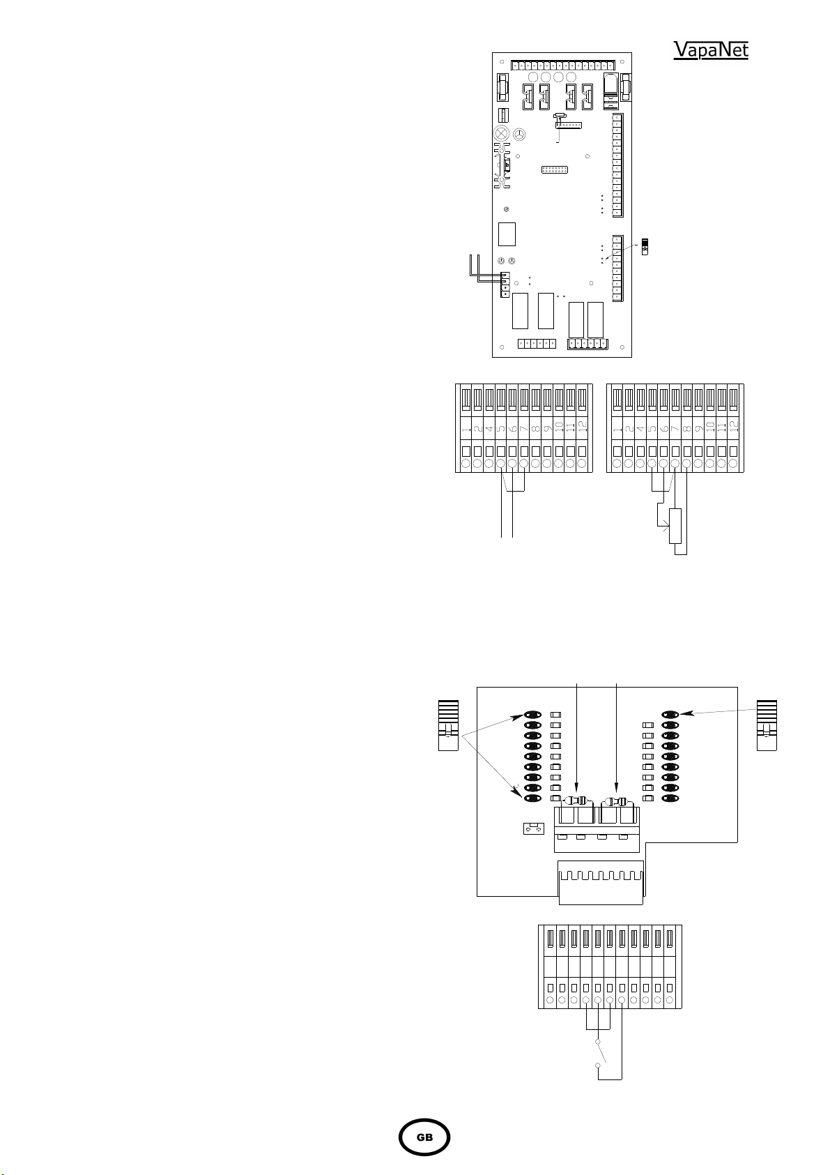
1.6.2 Proportional Control
The VAPANET Electrode Boiler (LExxP) models can
all be operated by either a potentiometric signal, a
lonworks network signal or by one of 6 standard
proprietary DC analogue signals.
Input signal:
Potentiometric control
0-5V
0-10V
0-20V
(Actually 0-18V – not phase cut)
2-10V
1-18V
4-20mA
Network
Master)
(Ensure jumper J1 is in place)
(Slave unit – demand generated by
Response:
8-100%
1.6.3 Control Signal Selection
Selection of the control signals is done a part of the
initial set-up procedure using the keypad display. For
confirmation that the signal has been selected, view
the information window. If the unit has not got a
keypad then this is done on the configuration board
1150634 mounted on the main control board 1150630
using the jumpers provided. The top right hand link
should be made indicating that the unit is an
“Electrode boiler” and the appropriate left hand link
representing the actual site control signal should be
linked using the jumper plugs provided
1.6.4 On/Off Control
Vapanet models can be operated by a single
step humidistat which has Volt-free contacts –
select control option Pot.
F2
CR2
CR4
CSP
configuration
resistor
NetCR7
J6
CR6
1
16
Vapac PART No. 1150630
J5
CR5
6
1
F1
CR2
18
1
J4
J3
J2
J1
6
16
CR3
1
10
Jumper J1
should be
fitted if
control
signal is
4 – 20 mA
DC 0 - 20 4 – 20 Ma POTENTIOMETRIC
VOLTAGE CURRENT CONTROL
CONTROL CONTROL min. 135 Ohms
Max. 10,000 Ohms
NOTE :- FOR CURRENT INPUT ONLY JUMPER J1 ON THE
1150630 CONTROL BOARD MUST BE LINKED.
UCP1UCP2
Vapac part no. 1150634
101112
J2
Electro
boiler
Pot high
Pot medium
Pot low
Softened
De-iron
De-min
Network
or slave
Full o/p
4-20mA
0-20v
1-18v
2-10v
0-10v
0-5v
pot
J1
CR2
1245678
9
HYGROSTAT WITH VOLT FREE CONTACTS (max.
RESISTANCE OF EXTERNAL CONNECTION 100
Ohms.
Page 20

1.6.5 Sensing Head
The units are designed to operate using a sensing
head, supplied by Vapac Humidity Control Ltd. which
should be connected as shown below. Other
propriety sensing heads which give a DC signal
may also be used, providing the control signal is
connected to control terminals 5 & 6, and the
sensing head is powered externally from the unit.
If “Frost Protection” is required do not connect
the thermistor input from the sensing head to
control terminals 1 & 2, which should be used to
connect the “frost protection thermistor” (part
number 1220275) instead. Frost protection is
selected via the display – Set the frost demand
above the minimum cylinder demand (LE units
>20%; LE(P) & LE(C) units >8%)
Note:
Use of the 24V supply of the VAPANET unit
to power other items of equipment will
invalidate the Vapac warranty.
1.6.6 Security Circuit / E.P.O. Shutdown
As standard units are shipped such that terminals 9 &
10 are provided for connection of an E.P.O.
(Emergency Power Off) switch or fire shutdown
facility. Other control interlocks, such as high limit
humidistat, airflow switch and/or fan interlock and time
switches etc. should be connected to terminals 11 &
12. Please note that if a display is connected to
the unit “DI1 Control Option” must be set to
“Shutdown”.
NB breaking terminals 9 & 10 will prevent any unit
operation including frost protection.
1.6.7 Load Shed Option
This can only be evoked via a display, either “hard
wired” or hand held. When this option is selected,
making the connection between terminals 11 & 12 will
activate the “load shed” software routine, which will
inhibit the operation of either the unit or in the case of
twin cylinder units unit or just the 2nd cylinder. This will
limit the power used during peak supply periods. If
this option is selected, the fan interlock, airflow switch
and/or high limit hygrostat should be wired into
terminals 9 & 10 with the EPO switch if fitted (as per
the drawing on the far right). It should be noted that
selection of this option will mean that frost protection
cannot be utilized.
Please note that if a display is connected to the
unit “DI1 Control Option” must be set to the
following:
Single cylinder units: “Load shed”.
Twin cylinder units: either “Load Shed Cyl 2” or
“Load Shed Both”.
20
6
125
4
CN2
NC(b)
G(B)
1 3
Vt(A)
Vapac’s accessory kit part numbers for sensors are
Remote Room mounted sensing head FVKIT-107 - 1
And
Remote Duct mounted sensing head FVKIT-108 - 1
Standard Operation Load Shed Operation
678
9
121011
5
4
2
1
E.P.O.
Fire Stop
Fan
Interlock
Air Flow
Switch
High Limit
Hygrostat
9871110
CN1
1 Vi G Vh G
124
E.P.O.
Fire Stop
Fan
Interlock
Air Flow
Switch
High Limit
Hygrostat
12
5
8
7
6
9
111012
Load Shed
Page 21
21
NB. The total cable length of the network (using the cable recommended by V.H.C.L.
– Our part
“system” (including the “master”).
configured].
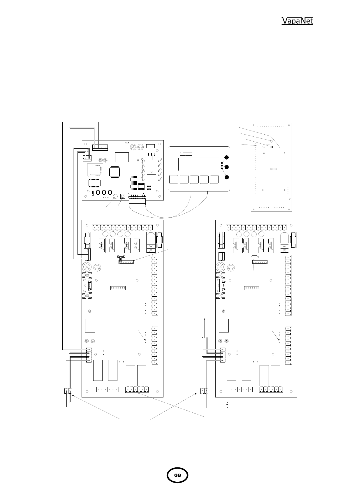
1.6.8 Master/Slave System
For larger duties, VAPANET “Electrode boiler” units can be interconnected and arranged to operate from one proportional signal as a
Master/Slave system. The system allows up to 10 cylinders to be linked in this way. The slave units will all be “on / off” units. The master
unit, to which the proportional signal is connected, can be “on / off” but will preferably be a “proportional” unit.
To “configure” a system, ensure that the control signal is zero [disconnect the control signal, or switch the units off at the front panel switch].
Press and hold the service pin on the master control PCB, until the user LED’s flash amber, release and check that the LEDs flash
red/amber/green, if not repeat the procedure. Then press the service pin (network button) on each of the slave control PCB’s in the order
that they are required to operate, the slave user LED1 will flash Green/amber until it is configured, once the light goes out [or flashes
red/off], proceed to the next slave. If units of different capacity are used, ensure that the master is equal to or greater than the capacity of
the slaves, and that the largest capacity slaves come on before the smaller capacity units]. Once this process is complete, confirm the fact
by pressing the service pin on the master PCB until user LED2 goes green [this step is not necessary if all nine slave cylinders are
number 8040251) is 500 m and it should be assumed that there is 1 m of cable in each unit of the
USER LED 2
Network LED
Network Button
USER LED 1
CR1
F2
CR2
FRONT VIEW OF 1150630 BOARD
1
CR4
UCP1
configuration
resistor
16
F1
CR2
18
1
V
0V
CR4
Vapac part no 1150631
9/24V ac Supply
40K 48K
Network Coms,
LED
CR1
F2
CR12
Display & Keypad
Net
CR1
J2
J2
1
J1
Network
Button
CR4
UCP1
configuration
resistor
16
F1
CR2
18
1
(Optional)
Vapac
xxxxxx xxxxxx
xxxxxxxxxxxxxxxxxxxxxxxxx
xxxxxxxxxxxxxxxxxxxxxxxxx
xxxxxxxxxxxxxxxxxxxxxxxxx
Esc
If unit is not fitted
with a display then
UCP1 configuration
resistor is fitted on
configuration board
1150634 which is
plugged into CR4
on the master unit.
PCB for "Master" or
"Slave" unit with display.
J1 see section 1.9.1
Link if control
signal is mA
current only.
J6
NetCR7
A B A B
CR5
1
16
J5
CR6
6
Vapac PART No. 1150630
1
Customers terminals within unit
located on low voltage rail
J4
16
J3
CR3
1
J2
J1
10
6
Remote Indications
CR6 gives the following remote indications
as Volt-free contacts:
Terminal 547 - Unit Run (normally open)
Terminal 546 - Unit Run (normally closed)
Terminal 545 - Unit Run (Common)
Terminal 544 - Unit Alarm (normally open)
Terminal 543 - Unit Alarm (normally closed)
Terminal 542 - Unit Alarm (Common)
Connection to
PCB for "Slave 1" to
"Slave 9" units.
Display if fitted
J1 see section 1.9.1
J1 see section 1.9.1
Not required forNot required for
slave unit.slave unit.
J6
NetCR7
CR6
1
16
J5
CR5
6
Vapac PART No. 1150630
1
Network Expansion to
slave units 2 to 9 or
other network
components.
J4
16
J3
CR3
1
J2
J1
10
6
Page 22

22
2.0 Start-Up / Operation
2.0.1 Start-up check list
a) Water supply and Drain Connections:
these should be connected as indicated
under Plumbing and in accordance with the
relevant local regulations. An isolation valve
should be adjacent to the unit. The
connecting metal plumbing must be
grounded close to the unit.
b) Steam Line: This must be connected
according to the installation instructions with
adequate slope and support.
c) Power supply: Wiring to the Vapanet unit
Should be by a qualified electrician and
comply with the relevant regulations using
appropriately sized cable and cable glands,
with disconnect and fuses to suit the
maximum fuse rating of the unit at the supply
Voltage. The disconnect/fuses should be
adjacent to the unit or within easy reach and
readily accessible.
d) Control Connections: Ensure the control
signal and security circuit are
correctly connected according to the relevant
instructions/diagrams.
e) VAPANET 24v / 9V Control Circuit
Transformer: The standard 24V
transformer used in the units has primary
winding for 200V, 220/240V, 380V, 415V, &
440v 50/60Hz connection derived from the
local electrical supply.
Note: 60Hz connection must be specified
with order as 230V 60Hz pump is required.
f) The maximum output & kW rating of the unit
is determined by a Current Set Plug. It is
therefore possible to down rate units to any
output, down to approximately 50% of the full
rated output.
g) Unit Configuration Plug (U.C.P.). Sets the
maximum current level for the unit. It is fitted
directly onto the control P.C.B. If a display is
fitted, it is the only resistor required to be
fitted to the control P.C.B.. However if no
display is present additional resistors need to
be fitted, to provide the microprocessor with
information relating to the control signal etc.
For ease these are fitted to a small PCB
fitted to CR4 of the PCB, and resistor
selection is via shorting links, see control
signal selection on page 13. If insufficient
information is available the unit will remain in
the “not_config” state (see “Used LED” on
page 19) until the information is supplied.
This additional information is provided via
the keypad – when the display is fitted.
2.0.2 Start-Up Instructions
First check:
a) That the transformer connection matches
supply Voltage.
b) That the security circuit is closed for unit
operation.
Close the electrical access panel.
Turn on the water supply to the unit.
Close disconnect/circuit breaker feeding supply to the
unit.
Close the On/Off switch.
The display (if fitted) will now show the Set-Up
procedure.
Follow the procedure by:
- selecting: the preferred language,
- Attaching the control PCB to the Display.
- nominating: the type/quality of the supply
water.
- nominating: the control signal (or Vapac sensor
when being used).
When the control signal has been nominated, the SetUp will be entered into the memory. The Set-Up can
then be checked by reading the information menu. If
an error has been made, it will be necessary to go
back to the Set-up menu. If no display is fitted the
information is set using the jumpers on the small
resistor PCB 1150634, fitted to CR4 of the control
PCB.
2.0.3 Commissioning/Start-Up
Once the Set-Up procedure has been completed, the
unit is available to operate according to the
requirements of the control signal.
When starting with an empty cylinder, the VAPANET
programme switches in the contactor and feeds water
in until the water reaches the electrodes, and current
starts to flow. Thereafter the VAPANET system will
continuously monitor and control the conductivity by
adjusting the amount of water drained and fed into the
cylinder.
With no demand the LE unit has the right hand light
will flash red the left hand light will be off. When the
demand increases or the unit is switched on the cyl 1
LED will flashing green Amber at rate depending on
the demand input and the actual current drawn, the
actual run current of each cylinder is monitored and
until the actual current has two feed above 95 % the
LED will flash green amber when the current is above
95% for two consecutive feed the light will flash red.
If twin cylinder unit the second cylinder starts in the
same way but only when the demand is above 50% to
unit
2.0.4 Features of VAPANET Electode
Boiler Unit
The VAPANET system of control is designed to adjust
the function to keep the unit operating in the face of
changing water quality in the cylinder and changing
electrode condition even if, in an adverse operational
circumstance, this results in some reduction in output
while the situation exists.
Foaming protection *
In particular, the VAPANET is designed to prevent the
onset of foaming and to introduce corrective drainage
to keep the unit working.
Automatic switch-off
The VAPANET PCB will stop operating in response to
extreme fault conditions identified as:
Drain Fault STOP (no drain function)
Feed Fault STOP (water not reaching cylinder)
In each case, the display will show the STOP
condition and a Help Message, the User LED’s on the
fascia will indicate the condition see table on page 16.
A warning signal will be available for remote
indication. The STOP condition of a VAPANET PCB
will be cleared via the key pad if a display is fitted or
by pressing the reset button on the fascia – then
switching the unit off and on.
ONLY BE TAKEN ONCE THE CAUSE OF THE PROBLEM
HAS BEEN ASCERTAINED AND RECTIFIED.
THIS ACTION SHOULD
Page 23
23
Size 4 (6 electrode)
2.1
Service Advice
The water hardness and the humidity demand at site will
determine the effective life of a steam cylinder. Units located
in areas with naturally soft waters will experience the longer
cylinder life, possibly upwards of 12 months in calendar
terms. With hard waters, a more frequent cylinder exchange
must be expected and cylinder exchange 2 or 3 times a year
can be the average situation. The normal scaling up of the
Vapac steam cylinder is outside the Vapac warranty.
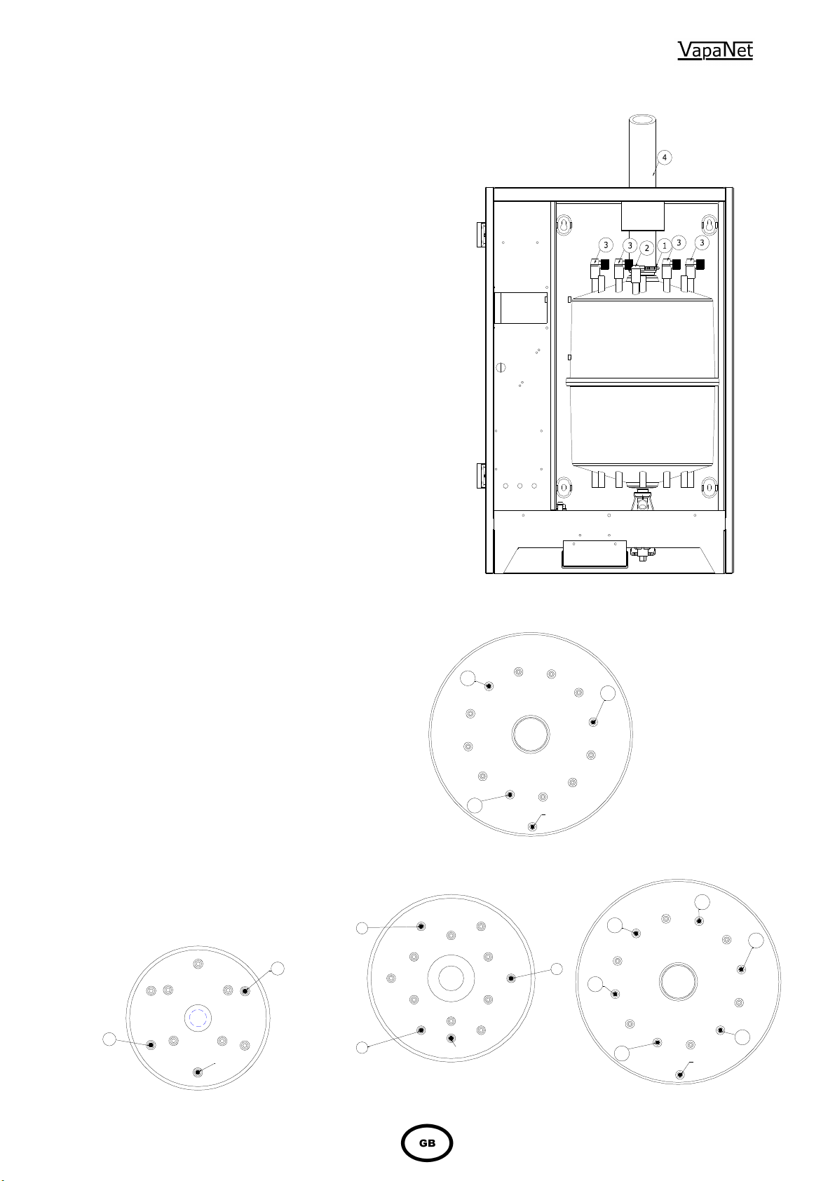
2.1.1 Procedure for cylinder Exchange.
1.
With the power connected to the unit, manually drain
the unit, by depressing (and holding) the Run/Off/Drain
Switch to the lower momentary drain position.
2.
Disconnect the Vapac from the incoming electrical
supply by means of the external isolator (disconnect
switch). This should be “locked off” to prevent
accidental operation.
3.
Unlock the access panel, and swing open to gain
access to the steam cylinder.
4.
Carefully ease off (lever) the electrode caps (1& 2). If
the cylinder is to be replaced, care should be taken not
to twist the electrode caps while removing the black
power caps. As the electrodes can rotate in the
cylinder bosses (if the plastic cylinder is hot) and lead to
unbalanced electrical loads.
5.
Loosen the hose clip (1) and disconnect the steam
hose (4) from the top of the cylinder.
6.
Using a twisting movement, lift the cylinder clear of its
seating in the feed/drain manifold and carefully remove
the used cylinder from the unit.
7.
Inspect the feed/drain manifold to ensure to ensure this
is clear of sediment.
8.
The drain pump can be removed for inspection and
cleaning, by following the instructions below.
9.
With the pump back in position, insert the cylinder into
the feed/drain manifold, pushing it down firmly to
ensure it is seated correctly.
10.
Reconnect the steam hose.
11.
Replace the electrode caps – ensure that they are
replaced in the same sequence as when removed. With
the cylinder full pin towards the front of the unit,
electrode number 1 will be to the left of the white
cylinder full electrode. Electrodes 2, 3, 4 etc will be
sequentially connected clockwise around the cylinder
(from number 1), when viewed from above. The cables
carry colour-coded sleeves to indicate the phase and
when connected correctly should follow the following
sequence. Red/Yellow/Blue/Red/Yellow/Blue when
viewed clockwise from the top. (NB The colour
sequence for two electrode cylinders will be Red/Blue.
12.
The connections to the cylinder should be routed in as
close as possible to their original route.
2.1.2 Typical Cylinder / Electrode Layouts
2
Component Identification
Fig 1
Fig 1
2
3
1
Size 4 (3 electrode)
Full Pin
4
3
5
1
Size 1 / 2 (2 electrode)
Full Pin
2
1
Full Pin
3
2
6
1
Full Pin
Size 3 (3 electrode)
See technical data for cylinder size fitted to your unit
Page 24
The pump is a sealed unit and should
removal / replacement are as follows
:
Steam and Condensate Hoses
24
Other Maintenance:
• Should only be carried out by a qualified
electrician.
• The steam cylinder should be drained prior to
carrying out any maintenance in the steam
section – This must be done prior to isolating
the electrical supply, i.e. before removing the
front access panel.
• The unit should be isolated from the electrical
supply before any cover or access panel is
removed.
2.2 Service and Maintenance
As the operation of the Vapac is entirely automatic, it
normally requires no attention on a day-to-day basis.
General cleaning and maintenance of the component parts
of the Vapac are recommended at intervals of about one
year, but this is largely dependent upon the frequency of its
use and the quality of the water supply. Where the Vapac is
part of an air-conditioning system being serviced regularly,
the Vapac should be inspected at the same time.
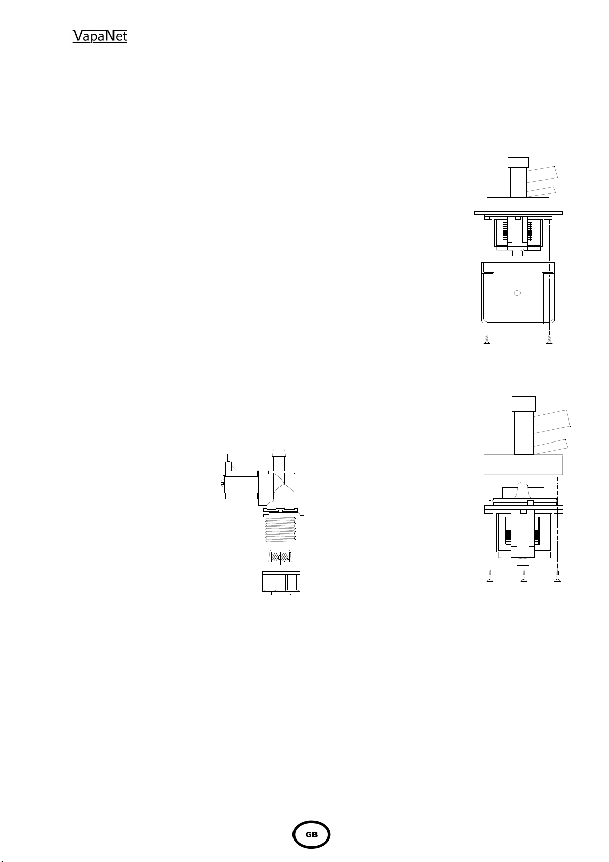
2.2.1 Feed Valve with Strainer
The nylon bodied solenoid valve incorporates a small nylon
strainer which is a push fit in the 3/4" inlet of the valve. With
a new plumbing installation, residual loose solid material in
the pipework could partially block the strainer after start-up.
If for this or any other reason a restriction of the water flow is
suspected (outside of supply pressure considerations), it
would be possible to clean the strainer as follows:Turn off the water supply to the Unit.
Undo the nylon nut connecting
the flexible connection to the
valve inlet .
The strainer can be removed
using ‘long-nosed’ pliers to grip
the centre flange provided on
the strainer for this purpose.
Withdraw the strainer.
Wash and replace it.
Reconnect and turn on water
supply.
Reconnect electrical supply to
allow unit to operate.
Note: Always replace the
strainer after cleaning as it is
required to prevent material
lodging in the valve seat or
blocking the small flow control
restrictor which is fitted in the
valve.
Valve with flow
Strainer
restrictor
3/4 Nylon nut with washer as
part of flexible connector
2.2.2 Drain Pump
not be dismantled. Instructions for
1) Place a bucket below the
pump, to catch any water
remaining in the housing
or pipework.
2) Remove the two screws
holding the pump cover &
lift clear.
3) Undo the three screws
holding the pump body to the
feed & drain manifold, and
remove it - any water trapped
in the pump will be released at
this point.
4) Fit the replacement pump by
following the above steps in
reverse order. Ensuring that the
O-ring surrounding the impeller
Housing is correctly seated, and
That it mates correctly with the
Feed / drain manifold.
The hoses used with and in the Vapac should be inspected at the normal service visits as part of normal maintenance. At the first signs
of deterioration, a hose should be removed and replaced.
Page 25
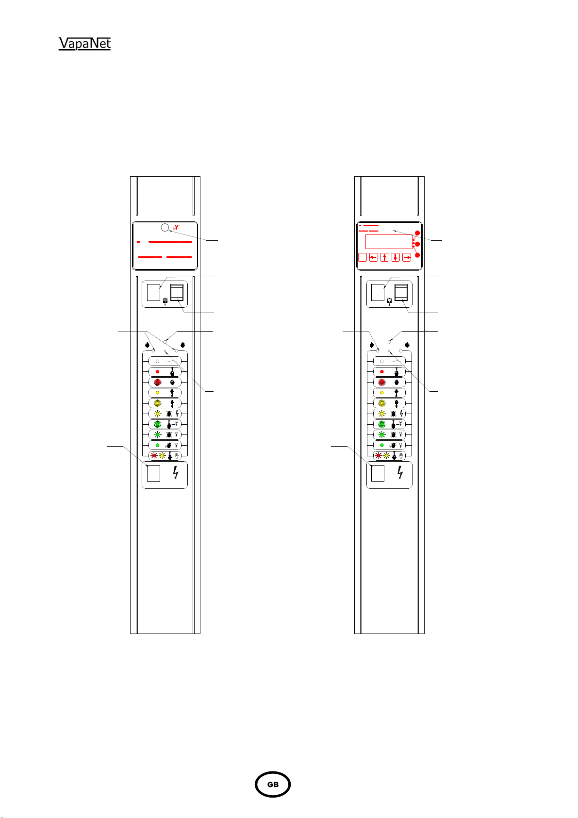
25
3.0 Location of Indicators and Controls
3.1 Positioning of Indicators and controls on Vapac ® Vapanet ® LE Units.
Vapac
Reset Button
Vapac
Esc
Alpha-Numeric
Display
User LED's
Power Available Neon
I
0
Cylinder 1 On/Off/Drain Switch
Cylinder 2 On/Off/Drain Switch
Network LED (Red)
Network Button
(Service Pin)
Power Available Neon
User LED's
I
0
1 21 2
Cylinder 1 On/Off/Drain Switch
Cylinder 2 On/Off/Drain Switch
Network LED (Red)
Network Button
(Service Pin)
Page 26
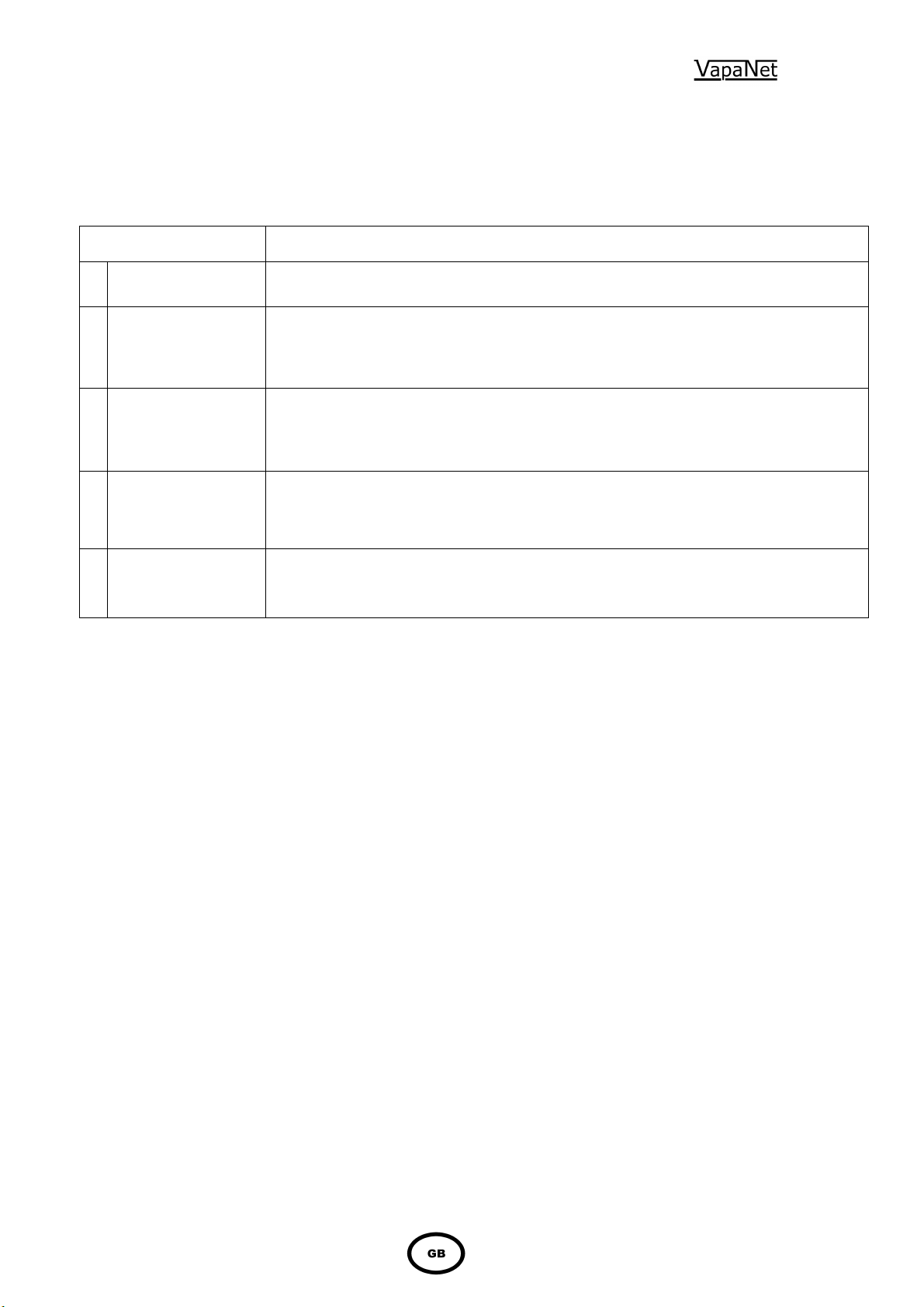
26
UCP1 valid.
3.2 Initial Set-up
User LEDs
During the initialisation process the User LEDs can be in one of the following
states
User LED State Description
RED Flashing
1
2 second period
RED/AMBER Flashing
2
2 second period
RED/GREEN Flashing
3
2 second period
User LED 1 -
4
RED/AMBER/GREEN
User LED 2 – OFF
User LED 1 & LED 2 -
5
RED/AMBER/GREEN
Unit initialising. If remains in this state, then unit does not a valid UCP1 fitted.
For units fitted with a display, the unit requires factory set-up (Number of Electrodes and
Number of Turns)
For units fitted with a configuration board, the UCP2 and/or UCP3 are not being detected.
UCP1 valid.
For units fitted with a display, the unit requires site set-up.
This state does not occur if the unit is fitted with a configuration board.
Unit in configuration set-up mode, as instructed from the attached display node.
Invalid configuration. The combination of UCP1 & UCP2 or UCP1 and the number of turns is
not valid.
Prior to the start of the initialisation process, the LEDs will flash Green, Red,
Amber repeatedly for 10 seconds to check that the LEDs are operation
correctly.
Remedy:
1 Check that UCP1 is fitted to plug fitted to CR4 pins 7 & 8 for units with Alpha-numeric
display or fitted to configuration PCB part number 1150634, which is fitted to CR4 if no
display is fitted. See page 16 of manual for more details. Ensure that good electrical
contact is made in each case.
2
a) For units without a display, check that UCP2 is fitted to the configuration PCB (see page
16 of the “Installation, Operation & Maintenance Manual”) and that jumper J2 is set to
“electro boiler” and J1 is set for the correct site control signal.
b) For units with a display, select “factory set-up”, logon using password “2121” and enter the
number of power electrodes and number of times the electrode cable passes through the
current sensing transformer (this information can be found in section 1.5 of the manual
and drawing LZD557 sheet 3 of 3).
replaced as a new unit will be sent out with the factory set-up pre-installed.
Please note that this will only be necessary if the PCB is
3 For units with a display: Enter “Set-up unit”, enter the “control signal” type and “site
voltage”, see Alpha-numeric display module operating manual..
4 For units with a display: Once the unit has been “set-up” press ok at the prompt “Apply
changes are you sure *?*” when the unit will exit this state.
5 For units with an Alpha-numeric display: Re-enter “Factory set-up” using password
“2121” and re-enter the correct “number of power electrodes” and “number of turns”
information, following the on screen prompts
For units without a display: Check that UCP1 & UCP2 are securely fitted to the
configuration PCB.
Page 27

27
3.3 Normal Run / Standby / Start-up – No User Intervention Required
Once the unit has initialised User LED 1 refers to cylinder 1, while User LED 2 refers
to Cylinder 2. For combinations of LED 1 and LED 2 being off, RED or RED Flashing
refer to following table.
User LED 1 User LED 2 Description
Cylinder 1 and Cylinder 2 (if fitted) in shutdown.
1 OFF OFF
2 OFF
Green Amber
Flashing Variable
RED Flashing
Variable Period or ON
3
4 Any
RED Flashing
1 second period
OFF
OFF
Green Amber
RED
The above are purely indications of the current state of the unit, and require no action
from the operator. When the state changes the indication will automatically change.
Or
Cylinder 1 in standby and Cylinder 2 in shutdown.
Cylinder 1 and Cylinder 2 (if fitted) in standby
Cylinder 1 Startup. Cylinder 2 (if fitted) in standby.
Cylinder 1 Online. Cylinder 2 (if fitted) in standby
The variable period is determined by the demand signal for cylinder
1 as follows,
Cylinder 1 demand LED ON RED LED OFF
<12.5% 0.5 seconds 3.5 seconds
<25% 1.0 seconds 3.0 seconds
<37.5% 1.5 seconds 2.5 seconds
<50% 2.0 seconds 2.0 seconds
<62.5% 2.5 seconds 1.5 seconds
<75% 3.0 seconds 1.0 seconds
<87.5% 3.5 seconds 0.5 seconds
>=87.5% ON RED Continually
Cylinder 2 Start-up
Cylinder 2 Online
Page 28

28
3.4 Fault / Service Indications – Requiring Operator Intervention.
User LED State Description
1 AMBER Drain Fault
AMBER Flashing
2
1 second period
AMBER Flashing
3
2 second period
GREEN Flashing
4
1 second period
Feed Fault
Over current Fault
Service Interval expired or low output.
GREEN Flashing
5
2 second period
6 GREEN Periodic Drain/Periodic Flush/Manual Drain completed.
RED/AMBER
7
1 second period
AMBER/OFF/AMBER/OFF
8
/GREEN/OFF
Periodic Flush/Periodic Drain/Manual Drain/Auto Flush in progress
Constant Output Active/Full Output via UCP3 (Master cylinder only)
No Voltage input
1, 2 & 3 Fault stop: Once the problem has been cleared the fault can be re-set by one of the
following procedures.
i) Units fitted with an Alpha-numeric display: Power the unit right off, using the local
isolator (not the unit on/off switch), waiting ten seconds then re-applying power. When the
message “Cylinder x drain fault” is once again displayed press the o.k. button, and the unit
will revert back to it’s operational state.
ii) Units not fitted with a display: Power the unit right off, using the local isolator (not the
unit on/off switch), waiting ten seconds then re-applying power. When the constant amber
“drain fault” indication is showing, press the unit “fault reset” button, which is located on the
fascia above the “Vapac” Logo.
4 Service Interval Expired / Low Output: Will be seen if either of the following occur.
a) Service Interval Expired: Seen if the unit has run for a period exceeding the service
interval of 4500 hours.
b) Low output: Seen if the cylinder has failed to reach 80% of the demand current after 30
hours run, or if the cylinder achieves this, then the current is monitored and an alarm
generated if the current subsequently falls to less than 60% of the demand current for
period of 4 hours run time.
If this indication is seen the cylinder should be inspected as soon as possible
If it is not convenient to carry out this inspection immediately it is possible to
postpone it for a short time.
3.4.1 To Postpone the Sevice:
Press the reset button once: The appropriate cylinder LED will change to constant “amber”
and the external alarm will be reset, allowing the unit to continue to run without an external
alarm.
a) Service Interval Expired: If the original alarm was due to this, the alarm will
be reinstated after the unit has run for a further 120 hours.
b) Low output: If the original alarm was due to this, the low output timer will be
reset and a new alarm will be generated if the unit fails to exceed 60% of the
demand current after a further four hours run time.
Page 29

29
When the alarm is repeated, it should be serviced immediately – and not postponed
further.
3.4.2 To Service the unit:
Press the reset button:
This will cause the appropriate LED to change to constant “amber”, the external alarm to be
reset.
Press the service button again:
(this should be within ten seconds of the first push).
This will cause a manual drain to be implemented. Once the drain is complete,
Isolate the electrical supply:
Inspect the cylinder: As described in the maintenance section of the operating and
maintenance manual.
Clean/Replace the cylinder: As described in the maintenance section of the operating and
maintenance manual.
Power up the unit:
Press the reset button:
This will cause the appropriate cylinder LED will change to constant “amber” and the external
alarm will be reset, allowing the unit to continue to run without an external alarm.
a) Service Interval Expired: If the original alarm was due to this, the alarm will be
reinstated after the unit has run for a further 120 hours.
b) Low output: If the original alarm was due to this, the low output timer will be
reset and a new alarm will be generated if the unit fails to exceed 60% of the
demand current after a further four hours run time.
Press the reset button again:
(this should be within ten seconds of the first push).
This will reset all the relevant timers including the hours run timer.
NB if the button is not pressed a second time then the alarm will only be postponed,
and will quickly return.
5 Event in Progress: This is a transitional state while the unit is actually performing a
particular routine. The LED indication is for information only and requires no user
intervention.
6 Event Completed: If one of the above conditions have been implemented, when it has been
completed, the unit by default will continue to run, however it is possible to change this to
“stop” (via a display either fitted or hand held) if this is the case this condition will be
exhibited, and the unit will not run until the condition has been reset, by either:
i) Units fitted with an Alpha-numeric display: Power the unit right off, using the local
isolator (not the unit on/off switch), waiting ten seconds then re-applying power. When the
message “event complete” is once again displayed press the o.k. button, and the unit will
revert back to it’s operational state.
ii) Units not fitted with a display: Power the unit right off, using the local isolator (not the
unit on/off switch), waiting ten seconds then re-applying power. When the constant green
“event complete” indication is showing, press the unit “fault reset” button.
7 Constant output:
i) Units fitted with an Alpha-numeric display: This is another transitional state, and once
the “constant output period” has expired, the unit will revert to normal “controlled” operation.
The LED indication will automatically revert to the cylinder’s “current state”.
ii) Units not fitted with a display: Once the testing of the unit is complete, the jumper J1
on the configuration PCB should be removed from the full output position and returned to its
normal operating position.
8 No voltage input: Check the wiring to CR6 of the “level sense” daughter board (part number
1150633). If the line voltage can be measured here, check the wiring between CR1 pins 5 &
6, of the same daughter board and CR2 pins 13 & 14 of the main control PCB. If this is also
correct then either the daughter board or the main control PCB is faulty. Once the fault has
been cleared the LED indications will revert back to the cylinders “current state”.
Page 30
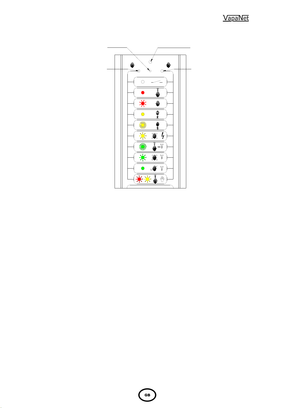
3.5 Fascia Label symbols
Cylinder 1
/periodic Drain/Flush in progress
3.6 Other Options
All selectable via a display (either Hard Wired or Hand held)
Feed With Drain
Used to lower the temperature of the drain water.
Frost Protectiion
When this is activated the unit will operate, at a preset demand level, if the temperature surrounding the unit falls
below a preset level, to prevent the pipework from freezing.
It is enabled by setting “frost demand” (via keypad/display) to >0 (it I disabled by setting “frost demand” to 0).
However the unit will not operate unless “frost demand” is set above the unit minimum demand level. Minimum
demand level for LE units is 21% and for LEP units it is 10%.
Frost demand is fully adjustable between 0 & 50%.
Timed Drain down.
Used to drain all the water from the cylinder if the unit remains on standby for longer than a preset (but adjustable)
time period.
For information on setting these options please see the display manual.
Network Button
(Service Pin)
User LED1
Red/Green/Amber
Unit Off
On-line
Standby
Drain Fault
Feed Fault
Over
Current
Service Interval
Service Routine/Manual
Periodic Drain/Flush completed
Service Routine/Manual
Constant Output Active/
Full Output via UCP3 (master
Expired
cylinder only).
30
1 2
Network LED
(Red)
Cylinder 2
User LED2
Red/Amber/Green
Unit Off
On-line
Standby
Drain Fault
Feed Fault
Over
Current
Service Interval
Expired
Service Routine/Manual
/periodic Drain/Flush in progress
Service Routine/Manual
Periodic Drain/Flush completed
Constant Output Active/
Full Output via UCP3 (master
cylinder only).
(If fitted)
Page 31
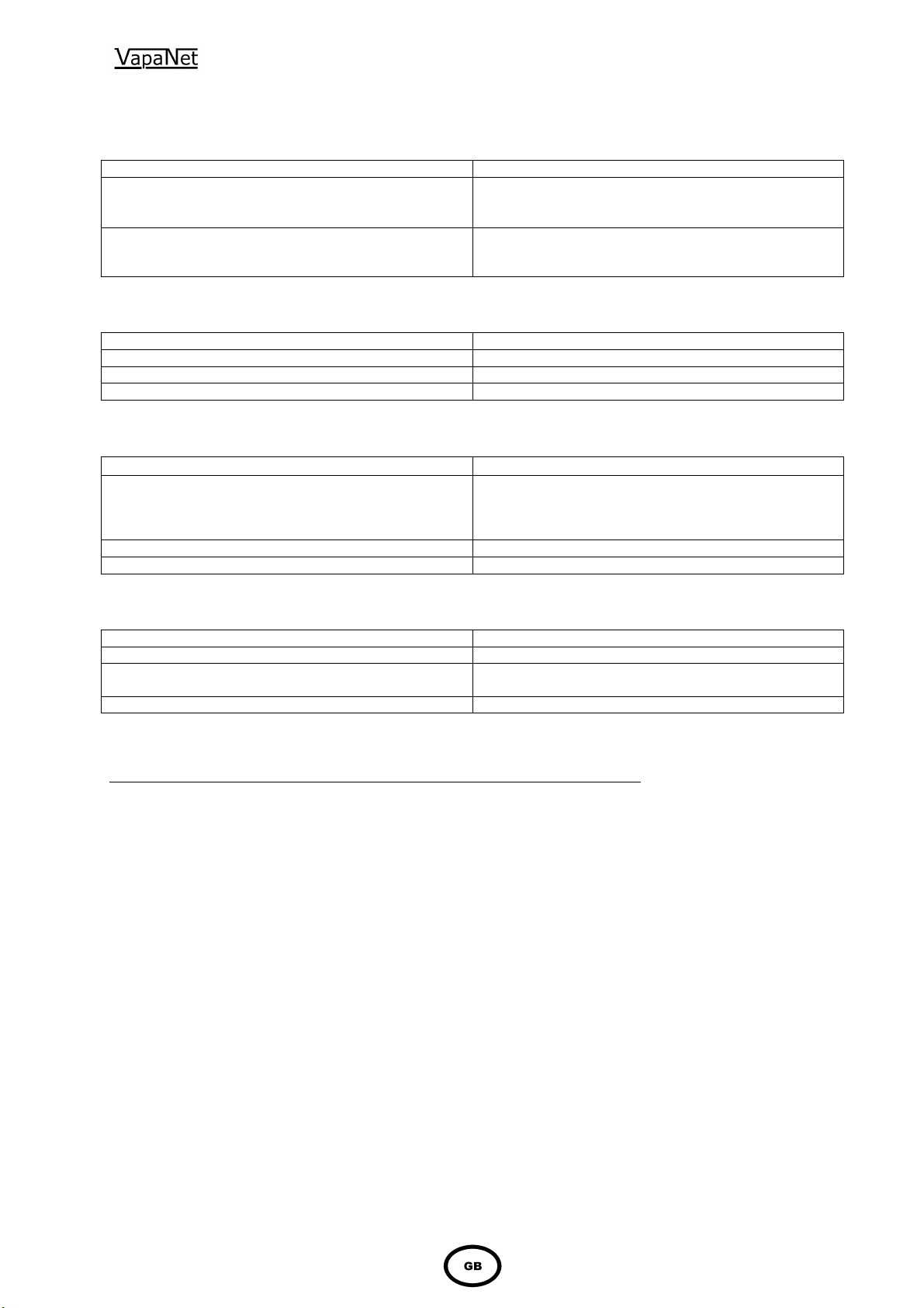
4.0 Trouble-shooting Check List
Symptom
Check/Cause/Remedy
Possibilities
Checks
Possibilities
Checks
Possibilities
Checks
Preliminary:
Use manual drain option to check pump operation
31
Power-On Neon – Off
Symbol-LED – Off
Display - Blank
Power-On Neon – On
Symbol-LED – On
Display - Blank
Check main power is connected and switched on.
Check power supply fuses.
Check if security circuit is open circuit
Check 24V 3.15A fuse mounted at top of Microvap
controller PCB 1150630
Automatic STOP – Feed Fault indicated on the Display.
Water is not connected Check water stop valve is open
Water connected but not reaching cylinder. Check internal Vapac hose connections for a leak.
Water in cylinder and overflowing.
Check float switch operation
Automatic Stop – Drain Fault indicated on the display.
Drain pump function impaired
Float switch failure Check float switch operation
Cylinder O/Let Blocked Check & unblock
Unit On-Line but inadequate or no steam production
If pump will not function, empty cylinder by disconnecting
at the tundish fill-cup the water supply hose to the
cylinder and draining the water into a bucket. Remove,
dismantle and clean pump.
.
Contactor not made Contactor coil, Float switches, Control PCB.
MCB’s tripped Cylinder Inspection, inspect elements and float switch
operation.
SSR’s not switching
SSR Check as described below,
Specialized check of the Solid State Relay
Important: The following check should be carried out by a competent electrician
Equipment needed: An AC Voltmeter, multi-meter set to full AC line voltage or suitable voltage test instrument.
Procedure: 1) Remove access panels from both the steam cylinder and electrical compartments
2) Ensure that the humidifier has an operational level of water in the cylinder. Switch unit
on and check that the display indicates “Vapac on line”.
3) Apply the voltmeter, set to the full line Voltage, across the output terminals of the SSR
being tested (i.e. the two terminals carrying the cabling to the elements).
Correct Voltmeter Response – oscillating between full and near zero Voltage.
If Voltmeter reads a constant near zero Volts, Check:
a) That the unit is not feeding water – if it is, wait until the feed valve closes and then recheck. The reason for this is that the SSR will hold closed while the feed valve is open).
b) That the control PCB is giving the correct pulsed D.C. signal (approx 5V D.C.) to the
SSR control input terminals.
SSR Replacement: A faulty SSR should be replaced with an SSR of the same (or higher) Voltage and
amperage rating. Disconnect the unit from the electrical supply. Disconnect the SSR and
undo the mounting screws. The SSR is bedded in thermal compound to assist heat
transfer – it is important that this is cleaned off, and a layer of fresh compound placed
under the replacement SSR, when it is secured in position.
Reconnect the SSR, reconnect the electrical supply and check the SSR function (as
above) before replacing the access panels.
Note: Use proprietary thread locking compound on the line voltage terminals of the
SSR’s.
Page 32
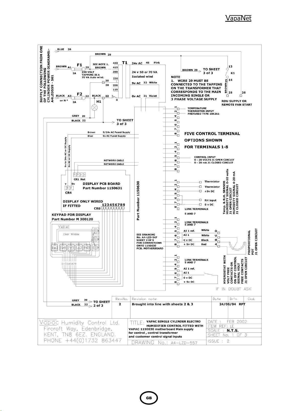
5.0 Wiring diagram
32
Page 33
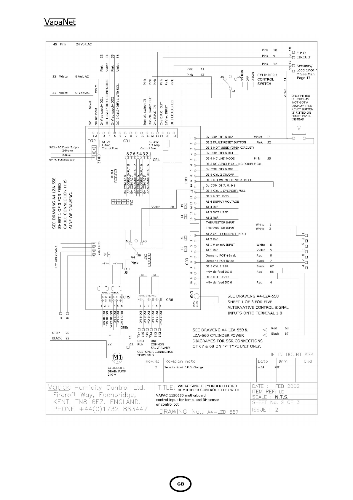
33
Page 34
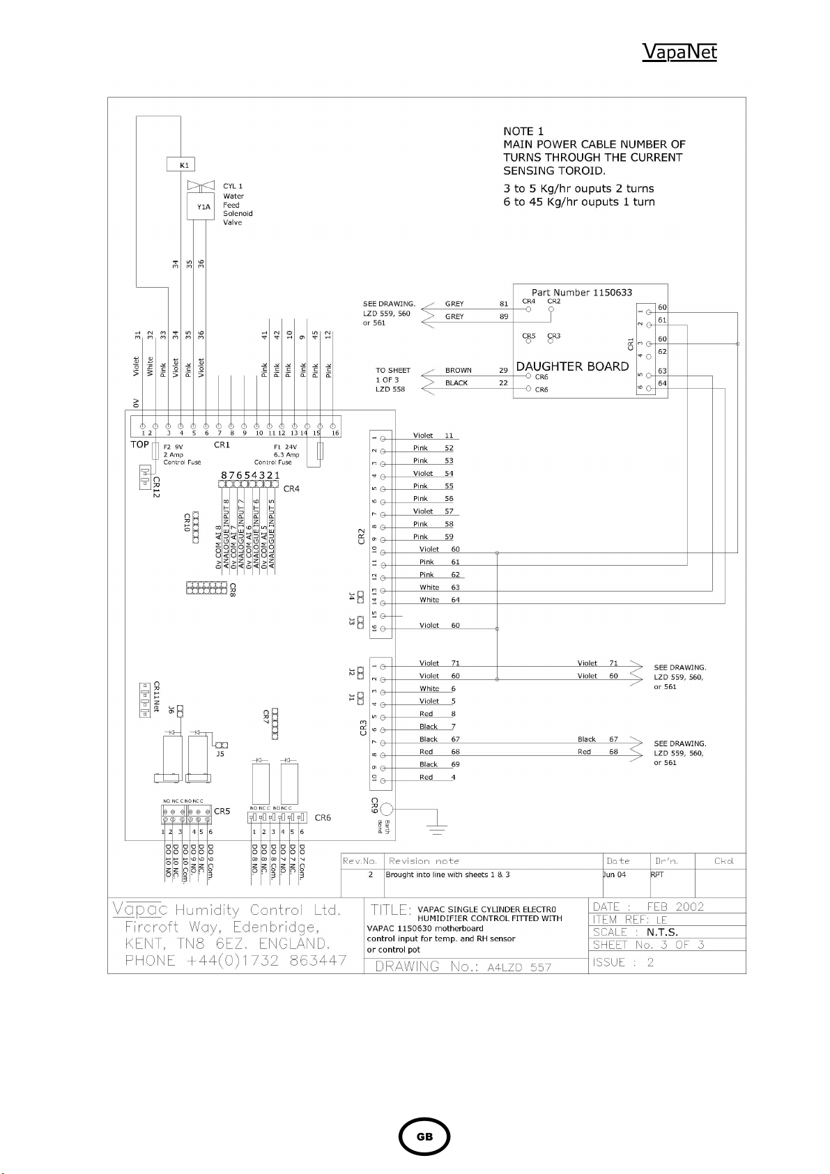
34 35
Page 35
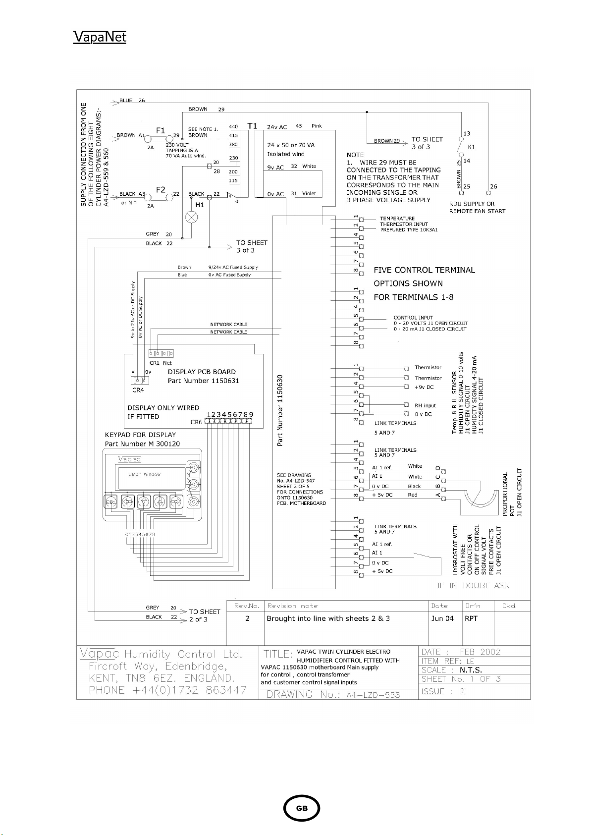
Page 36

36 37
Page 37
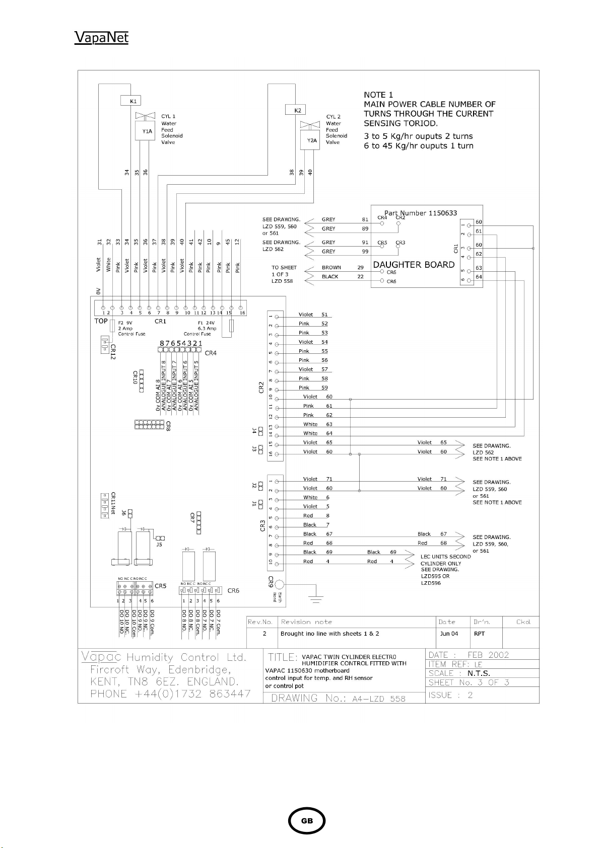
Page 38

38
Page 39
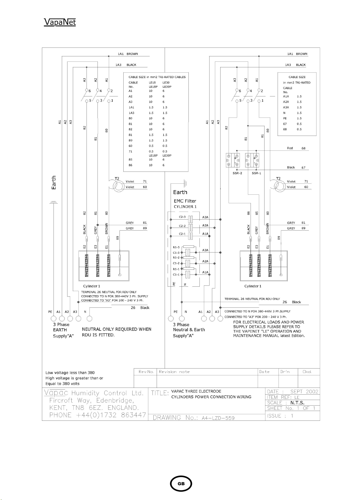
39
Page 40
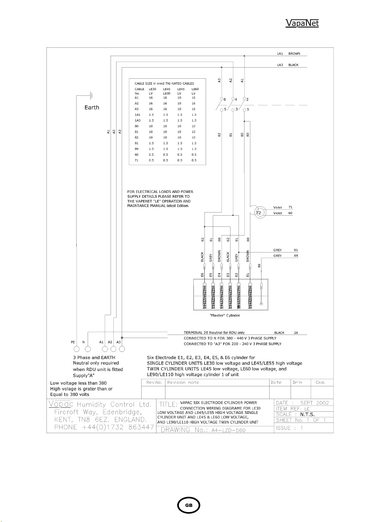
40 41
Page 41

Page 42
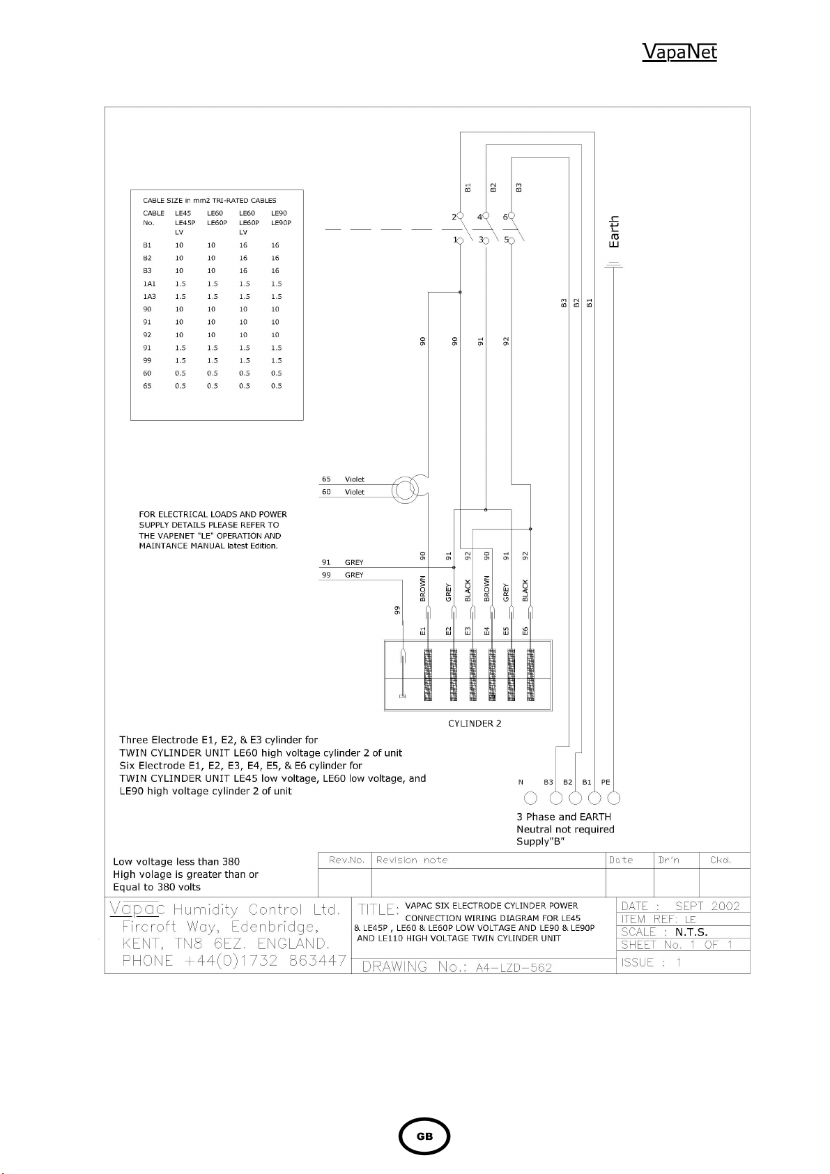
42
Page 43
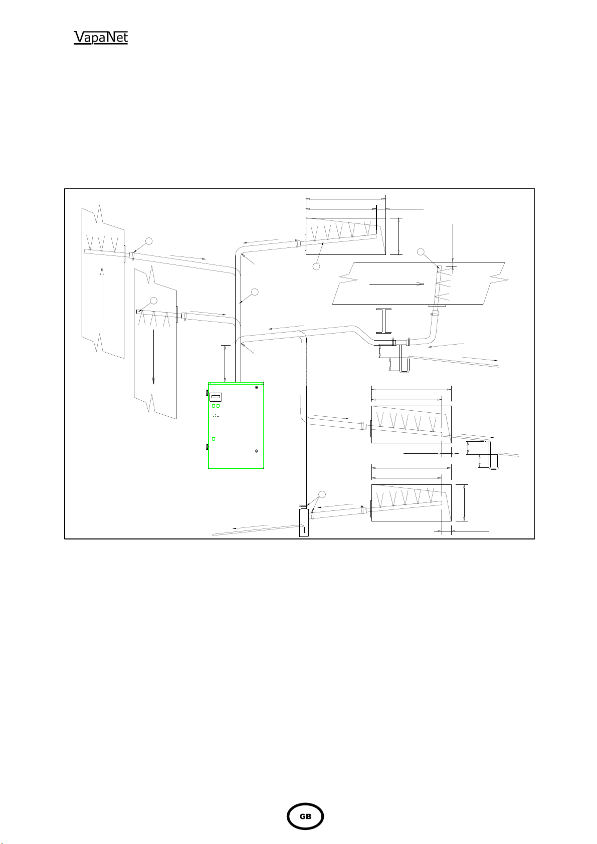
43
Vapac Humidity Control Ltd. Issue this as a guide
only, and accept no responsibility for
Appendix 1.
A Guide to Positioning Steam Pipes:
the positioning of any pipes in a system. This remains the responsibility of the Project
Design Engineer.
e
t
o
N
e
e
3
S
e
e
N
o
t
e
1
S
R
B
L
1
2
min 20mm
H
2
min 20mm
AIR
AIR
FLOW
AIR
Key;
1 Insulated Steam Hose
2 Steam Distributor Pipe
3 Hose Clip
4
Condensate Separator.
2
FLOW
S
e
e
N
o
t
e
1
min 300mm
1
R
R = 250 minimum
radius for 35 Ø pipe.
R = 500 minimum
radius for 54 Ø pipe
1
e
t
o
N
e
e
S
.
S
e
e
N
o
t
e
1
FLOW
X
Y
B
L
min 20mm
B
L
1
e
t
o
N
e
e
S
S
e
e
N
X = 60 minimum height
for a maximum
negative pressure
-600 Pa.
Y = 220 minimum height
for a maximum
positive pressure
2000 Pa.
S
e
e
N
o
t
X
Y
o
t
e
2
e
2
Fig 1
2
e
t
o
N
e
e
S
Notes:
1 Steam pipe to have a minimum slope from
the horizontal of 7° or 12% to allow the
condensate to drain back to the cylinder or
trap. NO HORIZONTAL RUNS. NO 90°
ELBOWS.
2 Water condensate tube to slope at 10° or
18% from the horizontal for condensate to
drain back to drain point.
3 Steam pipes which are mounted
horizontally must discharge vertically
upward.
4 Vertically mounted Steam pipes must
discharge horizontally facing upstream
airflow.
3
1
e
t
o
N
e
e
S
H
min 20mm
5 If the total pressure within a duct air flow
exceeds 2000 Pa and the static is below
2000 Pa then the probe may face
horizontally at right angles to the air stream.
6 Care should be taken to support steam
hose sufficiently such that no kinks are
formed which would flood with condensate
causing the bore of the tube to become
constricted, leading to excessive pressure
in the steam lines.
N.B Standard steam distribution pipes are
manufactured such that any condensate is drained
back towards the Vapac steam cylinder. Reverse
slope pipes are available, and are fitted with a drain
connector, to enable condensate to be taken away to
a suitable drain.
Page 44
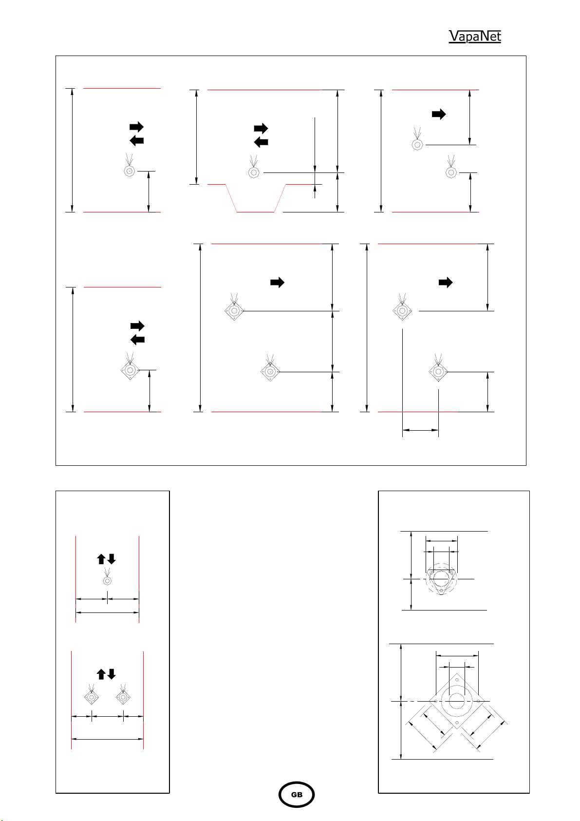
44
Figure 1
35 Ø 1 Steam Pipe 35 Ø 1 Steam Pipe 35 Ø 2 Steam Pipes
50% H
H > 300
H > 375
Fig 2
H < 300
30 min
H > 350
80 200 min
25%H
33% H
40% H
80 min. 200 min.
250 min.120 min.
H > 600
40% H
33% H
20% H
H > 400 < 600
30% H 60% H
200
54 Ø 1 Steam Pipe 54 Ø 2 Steam Pipes 54 Ø 2 Steam Pipes
shows the versatility of the steam
35 Ø or 54 Ø
1 Steam Pipe
50% W 50% W
W > 200
35 Ø or 54 Ø
2 Steam Pipes
25% 25%50%
W > 200
Fig 3
pipe / steam hose steam delivery system. It
also indicates where and how condensate
traps / condensate separators should be
used. If the steam pipe slopes such that the
steam connection is lower than the far end of
the pipe, this indicates that a reverse slope
steam pipe is required. This is fitted with a
drain point to allow condensate to be taken
away to a convenient drain.
Figure 2 shows recommendations on how to
space one or more steam pipes in a
horizontal duct.
Figure 3 shows recommendations on how
steam pipes should be spaced in a vertical
duct
Figure 4 shows mounting details for 35 and
54 Ø steam pipes
NB. The duct should be clear of obstructions,
transformations and bends until the steam
has been absorbed into the airflow. A guide
to calculating this distance is available from
Vapac – Part Number 0411047.
October 02
DUCT MOUNTING DETAIL
For 35 Ø Steam Pipe
150
65
3 x 5.0 Ø
min 200
min 80
Fixing
holes on
120 PCD.
DUCT MOUNTING DETAIL
For 54 Ø Steam Pipe
170 PCD
80
min 250
1
2
0
150
min 120
120
150
Fig 4
4 x 6.4 Ø
Fixing
holes on
170 PCD.
Page 45
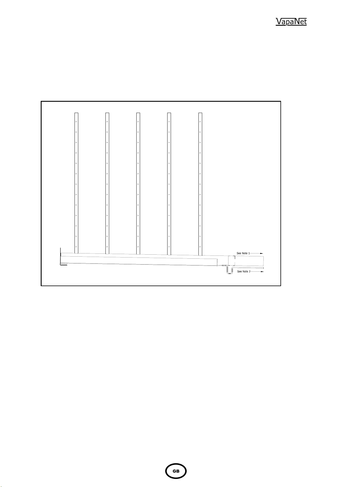
45
Appendix 2
A Guide to Positioning Multipipes:
Vapac Humidity Control Ltd. Issue this as a guide only, and accept no responsibility for
the positioning of any pipes in a system. This remains the responsibility of the Project
Design Engineer.
Notes:
1 Steam pipe to have a minimum slope from
the horizontal of 7° or 12% to allow the
condensate to drain back to the cylinder or
trap. NO HORIZONTAL RUNS. NO 90°
ELBOWS.
2 Water condensate tube to slope at 10° or
18% from the horizontal for condensate to
drain back to drain point. A suitably sized
trap will be required to prevent steam from
escaping via the condensate drain
connection.
3 Care should be taken to support steam hose
sufficiently such that no kinks are formed
which would flood with condensate causing
the bore of the tube to become constricted,
leading to excessive pressure in the steam
lines.
4 The duct should be clear of obstructions,
transformations and bends until the steam
has been absorbed into the airflow. Vapac
Humidity Control Ltd. Suggest a figure of 1.5
times the estimated absorbtion distance
stated on the “Multipipe” design sheet.
Which is supplied with the quotation.
5 Should it be necessary to slope the steam
hose away from the Vapac Boiler, it will be
necessary to fit a condensate separator to
remove the condensate at the lowest point.
This will need to be taken to a suitable drain.
Nov, 07
Page 46

Made in England by:
Vapac Humidity Control Ltd.
Vapac Humidity Control Ltd. reserve the right to change the design or
specification of the equipment described in this manual without prior notice.
April 2014
Printed in Great Britain
0410270
 Loading...