

Page 1

1
READ AND SAVE THESE INSTRUCTIONS
Key to be removed from door and retained by maintenance engineer
Minivap
Humidifier
Model DV4
Please read these instructions
BEFORE
installation and start-up.
Failure to observe manufacturers recommendations may invalidate warranty.
Vapac Humidification reserve the right to change the design or
specification of the equipment described in this manual without prior notice.
Vapac equipment is manufactured in Canada by:
Vapac Humidification Ltd.
Ed 2.05
0410145
Page 2

2
Minivap
Positioning the Minivap unit
DO's
DO mount the unit indoors.
DO mount the unit close to the steam nozzle
position.
DO ensure adequate service access to the front of
the unit -min. 70Omm (2'3").
DO remove the cylinder to gain access to the
mounting holes in the back of the steam section.
DO use M6 projecting type wall bolts or equivalent
to mount the unit in position.
DON'Ts
DON'T install the unit close to sources of strong
electromagnetic emissions e.g. variable speed lift
motor drives, KVA transformers, etc.
DON'T mount unit in an unventilated enclosure.
DON'T mount in a position requiring ladder access
to the unit.
DON'T install the unit behind a false ceiling or other
situation where an unusual malfunction (e.g. water
leak) would cause damage.
DON'T install the unit in an area which will be
hosed down.
DON'T install the unit where the ambient air
temperature can exceed 35°C (95°F).
DON'T mount the unit inside a cold-room or other
place where temperature and humidity conditions
can cause condensation on electrical components.
DON'T mount the unit where the sound of a
contactor opening/closing and water flow in a pipe
would be unacceptable e.g. libraries, private
apartments, etc.
DON’T place any object in front of an RDU (if used)
where humidity conditions can cause condensation.
DON’T mount on a duct or plenum.
Page 3

3
Minivap
Plumbing - Cold Water Connections
DO's
DO connect only to normal town piped water supplies.
DO install a stop-valve/shut-off valve and a strainer close
to the unit.
DO provide a water supply with sufficient pressur e and
pipe size to ensure an adequate flow rate to the unit -
1.2 litres/min (0.3 US gal/min).
DO use the flexible water connection provided.
DO thoroughly flush through new pipework before
connecting to the unit.
DON'Ts
DON'T connect to a water supply that has been softened
using a salt exchange system (sometimes called base
exchange or ion exchange system).
DON'T connect to demineralized water supplies.
DON'T overtighten the water supply connection with a
wrench or spanner- a flexible connection with nylon nut
with washer is provided to allow a firm hand-tightening - if
water seepage occurs, undo the nut to wipe the washer
clean and then re-seat it.
Plumbing - Drain Connection
DO's
DO use copper pipe or plastic pipe rated for
1
OO°C (212°F).
DO arrange to discharge drain water from the unit into a
vented and trapped drain at a position where flash steam
rising from the drain line tundish will not pose a problem
for the Vapac or other equipment.
DO provide adequate fall for the drain pipework to allow
free flow of water drained from each unit.
Do ensure drain line pipe size will accommodate water
being drained at the same time from other equipment
connected to it.
General
DO ensure metal drain and supply water pipework is
grounded electrically close to the unit.
Water quality:
Hardness: 50 - 500 ppm (3 - 30 gr.1 US gal.)
Conductivity: 80 - 1000 microSiemens/cm
Water Pressure: 0.3 - 8 bar (5 - 120 psig)
Water Flow Rate: 1.2 litres/min. (0.3 US gal.lmin)
Drain Flow rate: 4.5 litres/min. (1.2 US gal./min)
a) Tundish fill-cup
b) Steam cylinder
c) Drain pump
d) Drain trap
e) Feed valve with flow restrictor
f) Feed/Drain manifold
g) Water connection ¾
h) Flexible connector with 3/4" nut at both ends
j) Strainer
k) Stop valve
l) Ø35mm (1 3/8” steam hose + hose clips
m) Ø35mm (1 3/8” copper pipe + support
Tundish
Page 4

4
Minivap
Nozzle Installation
General positioning:
The position of the nozzle in the air-conditioning system
relative to other items- bends, filters, heat exchangers,
etc., is critical and must be decided by the design
engineer responsible for the project.
DO's
DO obtain project engineer's instruction/drawing for
chosen location of pipe.
DO obtain project engineer's instruction/drawing for pipe
position relative to the top & bottom of the duct (or sides
if airflow is vertical).
Steam Hose Connection
DO's
DO use steam hose/copper pipe of equivalent size to the
steam cylinder outlet dia. 22mm (7/8").
DO use Vapac steam hose or well insulated copper pipe.
DO keep steam hose as short as possible - under 2m
(6ft) for max efficiency.
DO arrange to have a vertical rise immediately over the
unit of 300 mm (l ft).
DO use the full height available between unit and steam
nozzle to provide maximum slope (min 12-20% for
condensate to drain back to the steam cylinder (or down
to a condensate separator). Always provide a continuous
slope.
DO provide adequate support to prevent sagging.
- fit pipe clips every 30-50cm (12"-20") support straight
lengths on cable trays or in heat resistant plastic pipe.
DO use a Vapac condensate separator or simple trapped
pipe connection to drain off condensate from extended
steam lines.
DO ensure radius hose bends are fully supported to
prevent kinks developing when in service.
DO add extra insulation to steam hose for longer runs
(2m-5m (6ft-1 5ft) and in cold ambient conditions to avoid
excess condensate and reduction in delivered output.
DO arrange for the condensate from the steam nozzle to
be discharged into the tundish installed for the drain
water from the humidifier. Use 6mm (1/4) diameter
(1OO°C / 212°F rated) tubing to connect to 6mm (1/4")
copper pipe or to discharge direct into the tundish.
DON'Ts
DON'T allow steam hose to develop kinks or sags.
DON'T include horizontal runs or 900 elbows in the
steam line.
Page 5

5
Minivap Electrical Connections
The wiring to the Minivap should be done by a qualified
electrician and the external overcurrent protection and wiring
should comply with the appropriate Regulations and Codes
of Practice. The standard Minivap unit is designed to suit
240V single phase electrical supply. Note: Minivap units for
USA/ Canada are fitted with UL/CSA rated dual Voltage
transformer and have supply Voltage options 240V and
12OV. As standard, the unit is connected for 240 V electrical
supply. For 120 V remove transformer link between H3 & H2
and fit links between H1 & H3 and H2 & H4.
External protection
A 25A fused disconnect or MCB should be used in the
electrical supply to the unit and this should be located
adjacent to the Vapac cabinet or within easy reach and
readily accessible.
Minivap Terminals (see Fig.11)
Terminals 1 and 2 are for the power supply connections.
Terminals 3 and 4 are for 24Vac supply for Vapac Supplied
Hygrostat.
Terminals 5 and 6 are for the external control circuit con
nections.
Important: the extemal wires connected to these two
terminals (5 & 6) must be Volt-free.
Terminals A and B are for connection of an RDU (Room
Distribution Unit). Note: An RDU can only be used with
units connected to 208V or 240V.
Control Circuit Connection
The Minivap can be operated by a single step humidistat /
hygrostat which has Volt-free contacts.
Note 1: This circuit operates at 5V d.c. provided by the
Minivap PCB.
Note 2: Minivap terminals 3 & 4 must NOT be used for
security circuit purposes.
Security circuit
When a high limit humidistat, interlock or airflow switch are in
use, these should be wired to interrupt the power supply to
the Mininvap unit either indirectly or directly.
Cable entry
Cable glands are provided and must be used to ensure
cables are held securely at the entry position.
Output Reduction
Using a very small-bladed screwdriver, the output of the
Minivap can be reduced by a small adjustable potentiometer
mounted on the control PCB 1150608. The adjustment
range is approximately 50%-1 00% of the full output which is
set by a resistor plug called the Current set Plug or CSP
located centrally on the control PCB The full output current is
marked on the CSP.
Fig 12: Opening of the Electrical Section
Releasing the electrical section:
To make the electrical connections to the unit It
is necessary to detach the electrical section. To
do this, open the door, disconnect the hose and
the electrode caps from the steam cylinder, then
remove the steam cylinder from the cabinet by
lifting R out the manifold.
Next undo and remove the two screws which
hold the electrical panel to the outer cabinet (see
Fig.2) and ease the whole electrical section
forward (see Fig.3) to disengage R from the
locating slots in the back panel.
Then undo the two holding screws to release K
from its top and bottom runner. The electrical
panel is then free and can be rested at an angle
within the cabinet (see Fig.4) to allow the wiring
connections to be made to the terminal block.
Completing the connection:
Remove the knock-outs in the top and/or side (for Minivap with RDU)
and fit the glands provided. Pass the cables through the cable glands,
make secure connections to the appropriate positions of the terminal
block then tighten the cable glands.
Note: If an RDU is fitted there is a smaller knock-out on the top and a
hard plastic grommet provided for the fan motor loads.
On completion re-attach the electrical panel to its runners, slide R back
and secure in position before replacing and reconnecting the steam
cylinder.
Important:
When replacing the cylinder make sure its O-ring seal and capping ring
are in position on the manifold
The position for the white cap (for the water level sensing electrode) is
marked by a label saying White', the electrode cable no. 1 must be put
on the electrode nearest to the white cap.
Making the electrical connection
Remove two screws indicated, slacken the two guide screws
then ease the electrical section forwards
1
2
3
4
5
6
B
A
AB12 3456
RDU
24V ac Supply
For Hygrostat
Hygrostat
Power Supply Connection
120V; 208V or 240V
Terminal Barrier
Fig 11:
Electrical
Connections
Page 6

6
Minivap
Start-Up Instructions
With installation, plumbing and electrical connection
complete: Turn on the water supply to the Minivap.
Close the fused disconnect or circuit breaker on the
electrical supply to the Minivap.
Put On/Off switch on facia panel to position 1.
The Minivap is now ready to operate when the
humidistat/ hygrostat switches the unit On.
Commissioning / Start-Up
With the correct electrical and water connections
completed, the Minivap unit can be switched on. When
the humidistat/hygrostat switches, electrical power is
applied to the electrodes and cold water flows into the
cylinder. The Minivap programme arranges for the water
to be introduced in stages until the full operating current
is reached. The level of electrical current depends on the
minerals present in normal town Water supply. It is
unlikely that the full operating current will be reached
when the cold water first enters the cylinder, in this case,
the cold water feed valve will close when the water
reaches the water level detection electrode, which is
located at the top of the cylinder and prevents the
cylinder overfilling.
The current which flows between the electrodes will heat
the water until it boils. The steam produced will be carded
up the steam hose to the steam pipel nozzle. As the
boiling continues more cold water will be added, bringing
in more minerals until the mineral concentration required
for full output is reached.
Thereafter the Minivap system will continuously monitor
and control the concentration of the boiling water by
adjusting the amount of water drained from and fed into
the cylinder.
Features of the Minivap Operation
The Minivap system of control is designed to adjust the
function to keep the unit operating in the face of changing
water quality in the cylinder and changing electrode
condition even if, in an adverse operational circumstance,
this results in some reduction in output while the situation
exists.
Note: The Minivap PCB disconnects the power to isolate
the electrodes during drainage to avoid earth leakage.
The Minivap unit will stop operating in response to
extreme fault conditions identified as:
High Overcurrent STOP
Drain Fault STOP (no drain function)
Feed Fault STOP (water not reaching cylinder)
The 'stop' condition on the Microvap PCB will be cleared
by switching the unit off and on. When a 'stop' condition
occurs, follow the service and maintenance procedure to
inspect the steam cylinder and drain pump.
End of Cylinder Life
The steam cylinder needs to be exchanged for a new one
when the output of the unit is excessively reduced by the
build-up of scale deposits.
Cylinder Exchange
Cylinder Life
The water hardness and the humidity demand at site will
determine the effective life of a steam cylinder. Units
located in areas with naturally soft waters will experience
the longer cylinder life, possibly upwards of 12 months in
calendar terms. With hard waters, a more frequent
cylinder exchange must be expected and cylinder
exchange 2 or 3 times a year can be the average
situation. The normal scaling up of the Vapac steam
cylinder is outside the Vapac warranty.
Procedure for Cylinder Exchange
1. With power connected to the unit, use the Manual
Drain position of the switch to empty the steam
cylinder.
2. Disconnect the Vapac from the electrical supply by
means of the external disconnect switch or circuit
breaker.
3. Open the lockable door to the cylinder chamber and
carefully ease off the red electrode caps and the
white electrode cap.
4. Loosen the hose clip and disconnect the hose from
the top of the steam cylinder.
5. Using a twisting movement, lift the cylinder clear of
its seating in the feed/drain manifold and carefully
remove the used cylinder from the unit.
6. Inspect the feed/drain manifold to ensure this is clear
of sediment.
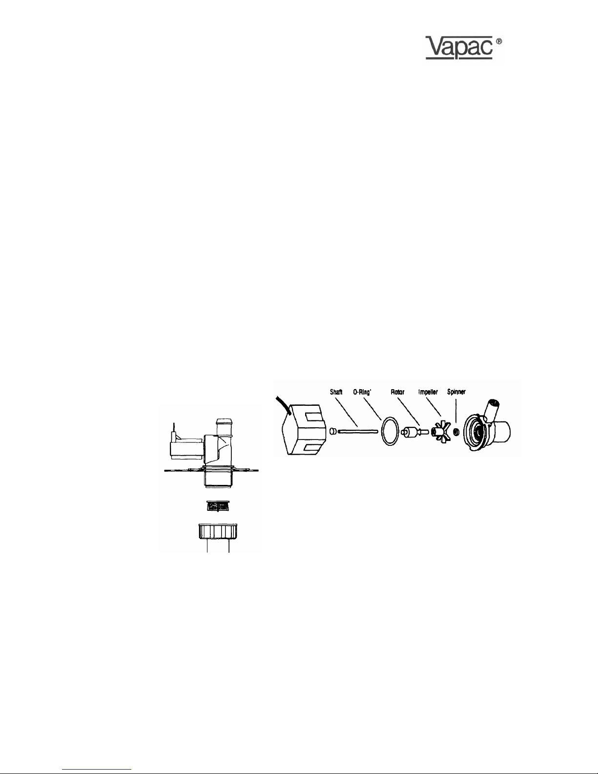
7. The small drain pump can be removed for
inspection/cleaning, by applying steady hand
pressure on h inlet housing to ease it back on its
mounting and to release it from its '0' ring connection
in the side of the feed/drain manifold. The diagram
shows the assembly arrangement of the feed/ drain
manifold and pump. The pump motor body is a
sliding fit onto its mounting plate.
8. With the pump back in position after cleaning, make
sure the O-ring seal and capping ring are in position on
the manifold then insert the cylinder into the feed/drain
manifold, pushing it down firmly, and reconnect the
steam hose.
9. The electrode caps must be reconnected in accordance
with the details on the collar supplied With the new
cylinder electrode no. 1 on the electrode nearest to the
white cap.
10.The Vapac unit is supplied with electrode cables routed
to avoid contact with the door. After a cylinder
exchange, it is important to replace the cables as close
as possible to their original route.
Page 7
7
Minivap
Service and Maintenance
As the operation of the Minivap is entirely automatic, it
normally requires no attention on a day-to-day basis.
General cleaning and maintenance of the component parts
of the Minivap are recommended at intervals of about one
year, but this is largely dependent upon the frequency of its
use and the quality of the water supply. Where the Minivap is
part of an air-conditioning system being serviced regularly,
the Minivap should be inspected at the same time.
Steam and Condensate Hoses
The hoses used with and in the Vapac should be inspected
at the normal service visits as part of normal maintenance,
At the first signs of deterioration, a hose should be removed
and replaced.
Feed Valve with Strainer
The nylon bodied solenoid valve incorporates a small nylon
strainer which is a push fit in the 3/4" inlet of the valve. With
a new plumbing installation, loose solid material in the
pipework could partially block the strainer after start-up. If for
this or any other reason a restriction of the water flow is
suspected (outside of supply pressure considerations), it
would be possible to clean the strainer as follows:
Turn off the water supply to the Unit.
Undo the nylon nut connecting the flexible water connection
to the valve inlet.
The strainer can be removed using 'long-nosed' pliers to grip
the centre flange provided on the strainer for this purpose.
Withdraw the strainer.
Wash and replace it.
Reconnect Pipework.
Turn on water supply.
Reconnect electrical
supply to allow unit
to operate.
Valve with flow
restrictor
Strainer
¾” Nylon nut with
washer as part of
flexible connector
.
Note: Always replace the strainer after cleaning as it is
needed to prevent material lodging in the valve seat or
blocking the small flow control restrictor which is fitted in
the valve.
Drain Pump
The pump should be inspected and cleaned regularly. It
is recommended that this be done at each cylinder
exchange especially in hard water areas. Failure to keep
the pump clear and operational will result in reduced
cylinder life.
To remove the pump for maintenance purposes proceed
as follows:
a. Depress and hold the manual drain switch to empty
the cylinder. The pump 'sound' changes distinctly once
the cylinder is empty. When this occurs release the
switch.
b. Disconnect unit electrical supply and follow the
cylinder exchange procedure.
C. If, due to an electrical or mechanical fault, the cylinder
cannot be emptied by the pump, it will be possible to
drain most of the water into a bucket by disconnecting
and lowering the top end of the tube which feeds cold
water to the cylinder from the fill-cup. The remaining
cold water will run into the base tray when the pump is
withdrawn from its'O' ring connection and/ or the
cylinder is lifted out.
d. Ease the pump free of the feed/drain manifold '0' ring
connection, slide it fully off its base plate and release
the connecting tube.
e. To dismantle and re-assemble pump refer to diagram
below.
In operation the stainless steel shaft remains stationary
while
f. the rotor and impeller rotate on ft. Remove all scale
build-up on the shaft so that the impeller can rotate
freely.
Ensure that the '0' ring seal is correctly positioned when
g. fitting the inlet housing to the main pump motor body.
When reassembling, make sure the brass spinner is
replaced on the shaft in front of the impeller. A smear of
multipurpose grease should be applied to the '0' ring so
that the impeller housing can be rotated into position
without distorting the '0' ring underneath ft and so
maintain the water seal.
Page 8

8
Minivap Trouble-shooting Check-List
Preliminary Check: -Use manual drain switch to check pump operation (On/Off switch in 'off position)
Symptom: Check/cause/remedy
Red 'Power-On' Neon -Check main power is connected and switched on.
- not lit -Check security circuit is complete (fan interlock, high humidity override).
-Check power supply fuses.
-Check Power-On neon.
Red 'Power-On' Neon - lit -Check the switch is in the position marked 1 (unit On position).
Water in the cylinder -Check Minivap internal control circuit fuse.
No current -Check humidistat.
-Minivap automatic STOP function has operated for one of the following reasons:
a) Feed Fault STOP
b) Drain Fault STOP
c) High Overcurrent STOP
If no obvious Feed Fault condition (a) exists, i.e. no water in cylinder, assume that (b)
or (c) applied. Carry out full inspection of cylinder and drain pump. Switching the unit
Off and On again cancels the automatic STOP condition but user should not put unit
back into service until the above action has been taken and the cause of the
interruption remedied.
-Slow start-up situation with a new cylinder. Low conductivity (soft) water. Add Alka
Seltzer to boost conductivity of the water. If above action is not successful and
condition returns, an alternative lower resistance cylinder may be necessary
Red 'Power-On' Neon - lit -Reduced output due to scale deposits,.
Water at top of the cylinder Remove cylinder for rinsing out and re-use o r fit a new replacement cylinder.
and low current
Minivap Model DV4 DV4-S
kg/h 1.5 – 2.75 2.75 – 5.5
Output Range
lb/h 3 – 6 6 – 12
kg/h 2.75 5.5
Max Output
lb/h 6 12
Power Rating kW 2.1 4.2
Electrical Supply 1Ø 60 Hz Volts 120 240 208
Full Load Current Amps 19 19 19
Fuse Rating Amps 25 25 25
Height mm 500 (19¾”)
Width mm 325 (12¾”)
Depth mm 230 (9”)
Service Weight kg 16 (35 lb)
RDU Height mm 185 (7¼”)
RDU Weight kg 3.5 (8 lb)
Steam Pipe/Nozzle No. 1
Steam Hose Diameter mm 22
Control System - On/Off
Steam Hose - internal diameter 22mm (7/8")
Steam Hose Length - recommended maximum 2m with continuous fall back to, the Minivap unit.
Condensate Hose - internal diameter 6mm (1/4")
Water Connection - 3/4" threaded connection to Minivap feed valve - use fle xible connector supplied with
unit which (underside) has VC threaded nylon nut at each end.
Drain Connection - has connection size 35mm (1 3/4")diameter unthreaded - use short length of hose to
interconnect (underside) onto copper pipe and discharge drain water to one side of
unit into an open tundish.
Page 9

9
1 2 3 4 5 6 7 8 9 10 11 12 13 14 15 16
K1Y1
Control PCB
Part No. 1150608
Vapac
Run
Off
Drain
ML
S1
T1
PE
Toroid
E1 E2White
14 AWG Tri-rated T.E.W.(600v)
14 AWG Tri-rated T.E.W.(600v)
18 AWG Tri-rated T.E.W.(600v)
18 AWG Tri-rated T.E.W.(600v)
100OHM
Level
sense
Isolator
0.5mm (Def_STAN 61-12 type 2)20.5mm (Def_STAN 61-12 type 2)
2
Steam
Cylinder
18 AWG Tri-rated T.E.W.(600v)
18 AWG Tri-rated T.E.W.(600v)
14 AWG Tri-rated T.E.W.(600v)
Fuse
3.15A
24v50VA
K1
H1
14 AWG Tri-rated
TEW (600v)
A
B
L2
L1
5
6
Hygrostat
Customer
Connections
Note:All unreferenced Cables are:-
0.5mm Tri-rated TEW (600v) also
marked 22 AWG
2
(Not supplied
By VHCL.)
RDU connection
when fitted.
208-240v ONLY.
120/208/240v supply
&
Earth
Wiring diagram
Itemref Quantity Title/Name, designation, material, dimension etc Article No./Reference
Designed by Checked by Approved by - date Filename Date Scale
Owner Title/Name
Drawing number Edition Sheet
B Note Re-security circuit added. 08/07/02 RPT Checked
R.J.K.
A3LZD436
Fircroft Way,
Edenbridge, Kent,
ENGLAND. TN8 6EZ
+44 (0)1732 863447
Vapac
R
D
Model-DV4
23/7/93 NTS
220v
120v
Contactor or relay to be used
to remove power if security
circuit is used. See manual.
4
3
24Vac supply
for Hygrostat
C Terminals 3 & 4 and associated cabling added 07/01/05 RPT
D Terminals 5 & 6 re-numbered correctly. Supply Voltages corrected. 07/02/06 RPT
Page 10

10
0410145 Mar 2006.
Ed 2.05
 Loading...