


Operation and Service Manual
VANTAGE TruckALL & VanGO Series
(3rd Edition)
VANTAGE VEHICLE GROUP

FOREWORD
Dear Customer,
Thank you for your purchase and use of Vantage Vehicle Group vehicle.
The purpose of this manual is to provide you some useful information and necessary technical data on operation, maintenance,
trouble-shooting and service of Vantage TruckALL & VanGO series. Since the automobile vehicles made by our plant are
mounted with different engine models, and each type of engine is provided with special-purpose manual on service, this manual
only gives a general description on engine. Therefore, the operation manual of engine will prevail in case of any
inconsistency with the operation manual of engine.
Your valuable comments on our products are warmly welcome. We will always carry out improvement to perfect the Vantage
TruckALL & VanGO series.
Vantage Vehicle Group

n
y
N
g
ght
N
Vehicle Type
Engine Type
Engin e Pow er
Manufacturer’s Product Number
Date of Production
Mini-Passenger Car Series
Va nG O P a ss e ng er Va n S e ri es
Note
The nameplate is mounted on the right central column inside the cabin, as shown in the above picture.
China First Automobile Group Corporatio
umber of
Passen
ers
Total
Wei
m
Content of Nameplate
ameplate
Position of Nameplate

Overall Height 1830
Overall Width 1475
Rear Tread 1200
Front Tre ad 1205
Wheelbase 2040
Overall Length 3902

Contents
Contents
Chapter I. Whole vehicle…………………………………………………………………………………………………………………………1
Section 1. General introduction……………………………………………………………………………………………………………1
Section 2. Operation of vehicle……………………………………………………………………………………………………………7
Section 3. Service and maintenance of vehicle……………………………………………………………………………………………20
Chapter II. Engine ……………………………………………………………………………………………………………………………….34
Section 1. Accessories to engine with carburetor…………………………………………………………………………………………34
Section 2. Accessories to electronic fuel injection type engine series……………………………………………………………………40
Chapter III. Chassis……………………………………………………………………………………………………………………………46
Section 1. Clutch…………………………………………………………………………………………………………………………46
Section 2. Transmission……………………………………………………………………………………………………………………49
Section 3. Drive-shaft………………………………………………………………………………………………………………………67
Section 4. Rear axle………………………………………………………………………………………………………………………68
Section 5. Suspension system………………………………………………………………………………………………………………75
Section 6. Steering system…………………………………………………………………………………………………………………81
Section 7. Braking system…………………………………………………………………………………………………………………91
Section 8. Tire and wheel…………………………………………………………………………………………………………………109
1

Contents
Chapter IV. Vehicle body………………………………………………………………………………………………………………………114
Section 1. Front door and rear slide door…………………………………………………………………………………………………114
Section 2. Rear door……………………………………………………………………………………………………………………128
Section 3. Seats…………………………………………………………………………………………………………………………130
Section 4. Instrument panel………………………………………………………………………………………………………………132
Section 5. Front windshield, rear windshield and side window…………………………………………………………………………133
Section 6. Bumper………………………………………………………………………………………………………………………136
Chapter V. A/C system…………………………………………………………………………………………………………………………138
Section 1. Heating system………………………………………………………………………………………………………………138
Section 2. Cooling system………………………………………………………………………………………………………………141
Chapter VI. Vehicle electrical equipment………………………………………………………………………………………………………155
Section 1. Power supply system…………………………………………………………………………………………………………155
Section 2. Igniting system………………………………………………………………………………………………………………166
Section 3. Electronic fuel injection code anti-theft system………………………………………………………………………………171
Section 4. Electrical equipment and its accessories………………………………………………………………………………………176
Appendixes………………………………………………………………………………………………………………………………………184
2
Operation and Service Manual on VANTAGE TruckALL & VanGO Series
Chapter I. Whole Vehicle
Section 1. General Introduction
I. VIN and engine number location
Fig. 1-1 VIN location
a—VIN located at front left of the instrument panel
b—VIN located at the surface of wheel cover under the driver’s seat
Chapter I. Whole Vehicle
Fig. 1-2 Engine number location
Engine number located on the right surface of the
cylinder block under the carburetor
1

Chapter I. Whole Vehicle
Operation and Service Manual on VANTAGE TruckALL & VanGO Series
II. Vehicle parameters
Vehicle type VANGO TRUCKALL
Rated passengers 6-8 persons 2 persons
Equipment weight 895kg 865kg
Rated load age —————— 545kg
Weight
parameters
Size
parameters
Performance
parameters
Total weight 1410kg
Axle-load
distributio
n
External size
Axle base 1940mm
Front suspension 844mm
Rear suspension 712mm
Min. Lift-off clearance 156mm
Angel of approach 26.1 °
Angel of d epart ure 31.7 °
Max. Steering a ngle of front inside wheel 37 °
Front
position
Max. speed.+ 110km/h
Max. climbing capacity ≥29%
Fuel consumption ≤6L/100km
Min. turn diameter 9m
Discha rged
pollutant
Front axle 480kg 475kg No load
Rear axle 415kg 390kg
Front axle 642kg
Full load
Rear axle 768kg
Length 3496mm
Width 1445mm
height 1841mm
Front wheel 1215mm Wheelbase
Rear wheel 1210mm
Kingpin i nclination angle 11°30′
Kingpin caster angle 5 °
Front wheel camber angle 1 °
Toe-in 2-5mm
CO 2.72g/km
HC+NOx 0.97g/km
2

Chapter I. Whole Vehicle
III. Main parameters and structure description
Parameters of engine assy. with transmission
Ararrangement
Cylinder bore X travel mm
Discharge
Compression ratio
Rated Horse Power
Max. torque N·m/r pm
Supply mode
Operation and Service Manual on VANTAGE TruckALL & VanGO Series
I-4, water cooled, 4-stroke, overhead camshaft EFI gas engine Carburetor
65.5×78 65.5×72 62×72
1.051 0.97 0.87
9.0 8.8 8.7
55 45 40
83/3000-3500 74/3000-3500 66/3000-3500
Multipoint closed loop electronic control fuel injection system -
3

Operation and Service Manual on VANTAGE TruckALL & VanGO Series
Chapter I. Whole Vehicle
Capacity parameters Tire (general cross ply 165/70R13 (5.00-12ULT)
Fuel tank: 37L Rim(general cross ply) 5.00×13 (4.00B×12)
Engine lubricating system: 3.5L Tire pressure(general cross
ply)
Cooling system: 4.0L Front wheel 200kPa (21kPa)
Transmission: 1.3L Rear wheel and spare wheel) 230kPa (260kPa)
Rear axle: 1.3L Steering gear
Steering gear: 0.6L Type Gear rack type
Structural description Braking system
Drive-shaft Running braking system
Type
Rear axle Brake
Front brake Disk, floating braking tongs (selecting drum brake)
Rear brake Drum, clearance regulated automatically
Type Single stage speed reduction,
Final drive ratio 5.125 Arrangement
Axle housing type Pressing, welding and integral Vehicle body Bearing and full metal enclosed body, 5 doors(2 front
Half axle type
Differential type
Suspension
Front suspension
Rear suspension Longitudinal semi-ellipse plate spring,
Single joint, open type, hollow, double
universal joint
gear final drive
Semi-floating
Planetary taper gear
Strut swing-arm independent suspension,
coil spring, equipped with stabilizer bar,
bi-directional hydraulic tube absorber
bi-directional hydraulic tube absorber
arrangement Bi-pipe hydraulic braking, with braking force
Braking system
distribution valve, equipped with vacuum booster
Stay control, act on two rear wheel
doors, 2 slide doors and 1 back door), three-point seat
belt, panoramic camber windshield
4

Chapter I. Whole Vehicle
IV Repair regulations
1. When repairing electric parts, the joint of binding post of battery
negative pole should be disconnected first, in order to avoid electric
shock or short; the step is to unscrew the nut on negative pole slice
end, to separate ground wire and binding post.
2. When jacking up the front end or back end with lifting jack, be sure
first to aim the lifting jack at the central position of front suspension
or rear axle housing, then to bear a vehicle, see Fig. 1.1-3, Fig. 1.1-4.
3. When repairing a vehicle after its front end or back end, be sure to
put a safe dais under carriage to bear the body firmly, see Fig. 1.1-5,
Fig. 1.1-6.
Note: When putting safe dais under carriage, prevent the safe dais
from bumping or contact the parts of carriage (such as fuel pipe).
Triangle bolster should be put under the front and back sides of left
and right wheels that are not jacked up, to prevent a vehicle from
moving forward and backward
Fig. 1.1-3 Sketch of jack used in back side
5
Operation and Service Manual on VANTAGE TruckALL & VanGO Series
Fig. 1.1-4 Sketch of jack used in front side
Fig. 1.1-5 Sketch of safe bench placed in front side

Operation and Service Manual on VANTAGE TruckALL & VanGO Series
Chapter I. Whole Vehicle
Fig. 1.1-6 sketch of safe dais put in back side
4. When lift a vehicle with a lifting rack, guarantee that lifting arm does not
contact to brake pipeline, fuel pipeline, bracket or any other parts.
The lifting position of listing rack and listing arm on a vehicle is shown as
Fig. 1.1-7, Fig. 1.1-8. When the vehicle raises four wheels separating from
the ground, try to drive the body from two sides, after it is confirmed that
the vehicle may not drop, the reparation begins.
After the vehicle is raised, the lifting rack should be locked.
Fig. 1.1-7 Front end bearing position
5. When repairing, disassembled parts must be placed a complete
set after a complete set or in order with pallet, tray or bulkhead,
to avoid in a mess or in wrong position.
6. Each bolt must be installed in original position. The bolts or
nuts with specified screw-down moment should be screwed
down with torsion spanner instead of yourself feeling.
7. The dismantled oil seal, sealing gasket and “O” hoop in
disassembling had better be scrapped, new ones shall be replaced
Fig. 1.1-8 Back end Bearing position
when reassembling.
8. When repairing, refer to this manual as much as possible, and
operate according to the description.
6

Chapter I. Whole Vehicle
Operation and Service Manual on VANTAGE TruckALL & VanGO Series
Section 2 Operation of vehicle
I. Operation description
(I) Key
Two key are provided for a vehicle (Key with code anti-theft system
sees Chapter 6).
Vehicle key has the following functions:
1. To control the power supply of vehicle electrical equipment.
2. To unlock and lock vehicle door lock.
3. To unlock and lock fuel tank cap
(II) Door lock and door window
a) Front door lock
Unlocking and locking outside a vehicle, as shown in Fig. 1.2-2.
Turning key clockwise can unlock left front door lock, turning key
anticlockwise can unlock right front door lock, vice versa, lock the
door lock.
Unlocking and locking inside a vehicle, as shown in Fig. 1.2-2. Lift
inner lock button, pull inner handle, vehicle door is unlocked; shut
vehicle door, press inner lock button, vehicle door is locked.
Note: When vehicle is running, inner lock button must be pressed, to
avoid accidentally pulling inner handle to open the vehicle door.
The door can be locked outside vehicle without key. First, open
vehicle door, press inner lock button, then lift the handle outside the
door, the door is locked, as shown in Fig. 1.2-3. But outer handle
should be pulled once, to affirm if the door is locked really or not .
Fig. 1.2-1 Fig. 1.2-2
Fig. 1.2-3
2. Middle door lock
When unlocking outside vehicle, pull backward outer handle, vehicle
door is opened.
Unlocking and locking inside vehicle, as shown in Fig. 1.2-4. Lift
inner lock button, pull backward handle, slide door is opened. Pull
forward inner handle to close vehicle door, press inner lock button,
vehicle door is locked.
7

Operation and Service Manual on VANTAGE TruckALL & VanGO Series
3.Rear door lock
Fig. 1.2-4 Fig. 1.2-5
Unlocking and locking outside vehicle is shown as Fig. 1.2-5. Insert
key into key hole, turn anticlockwise 90°, take out the key, then
hold on outer handle manually, press lock cylinder with thumb and
pull backward, rear door is opened; after the door is closed, insert
key into key hole, turn clockwise 90°, rear door is locked.
4. Rising and falling of front vehicle door
Turn clockwise the lifting crank of right front door glass, right side
glass rises; turn anticlockwise the lifting crank of left front door glass,
left side glass rises, vice versa glass falls.
5. Side door window
If you want to open push side window, push the button to make the
window reach the locking position. If you open push-pull side window,
press button, at the same time, pull backward handle, up to the
expected position.
(III) Seat and body
8
Chapter I. Whole Vehicle
1. Front seat
(1) Fixing
Hang two lock hoop in seat front end on projective latch hook,
press the handle up to lock-up, in this way the seat can be fixed, as
shown in Fig. 1.2-6, Fig. 1.2-7.
Front seat and backrest is monolithic, so when repairing engine, the
seat should be tilted. Pull back shackle, raise backrest angle modifier
to make the backrest reach the most pitching position, tilt backward,
then the seat can be operated.
Fig. 1.2-7
(2) Regulating back and forth
There is a control handle under the seat, lifting the handle upward can
regulate the seat back and forth, see Fig. 1.2-8.
Note: When driving, do not regulate seat to prevent danger.

Chapter I. Whole Vehicle
Operation and Service Manual on VANTAGE TruckALL & VanGO Series
(3) Backrest regulation
Seat backrest is tilt able. When regulating, raise handle, select
backrest angle, release the handle, the backrest is locked, see fig.
1.2-9.
2. Backseat
The second row seat can tilt a certain degree forward, in order to be
easy for passengers on the third row seat to get on and get out, which
is shown as fig. 1.2-10, the regulation of backrest degree is the same
as the front seat.
When the third row seat needs to regulate, raise handle, make the
backrest forward level, then tilt entire seat 90°。
10
Fig. 1.2-7
Fig. 1.2-10
3. Body
CA1010, and CA1010A Mini-Cargo Car Series with single row seat,
The body is full metal rear body. Body safety frame is fixed on cab
rear wall board, the body can be opened in three sides. Body panels
are connected with self-locking catch and staple, with quick
disassembling and assembly type. Pulling handle outward can make
staple and catch separate to open the body; buckle staple and catch
together, push handle, the body is closed and locked.
(IV) Fuel tank cap
The Oil filler of fuel tank is on the right side of vehicle. Inserting key
and turning anticlockwise can lock wicket, vice versa open, see Fig.
1.2-11. After opening the wicket, turning anticlockwise fuel tank cap
can open it, when turning clockwise and hearing “ka ka” sound, the
fuel tank cap has been locked reliably.
(V) Seat belt
This vehicle uses automatic crimping seat belt.
When fastening seat belt, insert the tongue into the buckle, until you
hear a click, it is locked. Press the red button on the buckle, the seat
belt can be unfastened.
Fig. 1.2-11 Fig. 1.2-12

Operation and Service Manual on VANTAGE TruckALL & VanGO Series
Note:
·Seat belt is designed according to human body’s structure, so the
user must use it on the requirement, the lower end position should not
exceed abdomen, shoulder seat belt should sling over chest and
shoulder.
·Seat belt should keep clean, to avoid oil, chemicals, particularly
electrolyte corrosion, if it is dirtied, wash it with appropriate soap and
water.
·If seat belt is damaged, please replace a new one.
·One seat belt is used only for one person, children can not use the
same seat belt with their parents.
·The users do not embellish the seat belt to avoid influencing its
operation performance.
(VI) Jack, spare wheel kept position
1. Jack
Put jack under left front seat. Raise seat and engine cowl, turn
anticlockwise jack handle spindle to be taken out. When putting it,
turn clockwise jack handle spindle to be put there, see Fig. 1.2-13.
Put jack handle spindle on the left lower side of the instrument panel,
see Fig. 11.2-14.
2. Spare wheel
Open rear vehicle door, unscrew tightening bolt, then the spare wheel
can be removed.
Fig. 1.2-13 Fig. 1.2-14
Chapter I. Whole Vehicle
(VII) Instrument panel and control mechanism, see Fig. 1.2-15.(taking
hard plastic instrument panel as an example)
Fig. 1.2-15 Instrument
1. Braking oil tank filler 2. Lighting and turn light switch 3. Choke pull button 4.
Electric wiper and washer switch 5. Alarm lamp switch 6. Odometer 7. Warning
indictor lamp 8. Water-temperature gauge 9. Fuel meter of fuel tank 10. Ash tray 11.
Glove box 1 2. Blower and air-conditioner switch 13. Air-cond itioner contr ol panel 14.
Ventilating system 15. Ignition equipment 16. Fog-lamp switches 17. Selection electric
part switches 18. Cigarette lighter(selection) 19. Radio cassette player
(VIII) Combination instrument, see fig. 1.2-6
1. Speedometer
Indicate the instantaneous speed of vehicle and record accumulation of
miles.
2. Fuel meter of fuel tank
When ignition switch is on gear ON, fuel meter indicates the fuel
quantity within fuel tank.
11

Chapter I. Whole Vehicle
Operation and Service Manual on VANTAGE TruckALL & VanGO Series
When fuel gauge pointer points at F, the fuel tank is full; when it
points at E, the fuel tank is nearly empty, see Fig. 1.2-17.
(a) for engine with carburetor (b) for electronic fuel injection
engine
Fig. 1.2-16
3. Water-temperature meter
When ignition switch is on gear ON, pointer can indicate the coolant
temperature within engine. When the pointer fluctuates in C section,
engine water temperature is normal; when the pointer exceeds H,
showing the temperature is over high, if the engine is over hot, do not
continue to drive, see Fig. 1.2-18.
Fig. 1.2-17 Fig. 1.2-18
4. Motor oil pressure indicator lamp (red)
When ignition switch is on gear ON and the engine flameouts,
indicator lamp is bright; after
The engine starts, the indicator lamp should black out. If the engine
starts the lamp is still bright or the lamp is lightened during running,
showing engine lubricating oil pressure is deficient, it should be repaired
immediately, see Fig. 1.2-19a.
5. Charge indicator lamp (red)
When ignition switch is on gear ON and engine flameouts, indicator
lamp I bright; after the engine starts the lamp should black out. If the
engine starts the lamp is still bright or the lamp is lightened during
running, showing the engine has not charged up to battery or circuitry
fault appears, it should be repaired immediately, see fig. 1.2-19b.
Fig. 1.2-19
6. Left-turning indicator lamp (green), see Fig. 1.2-19c.
7. Right-turning indicator lamp (green), see Fig. 1.2-19d.
8. Distant light indicator lamp (blue), see fig. 1.2-19e.
9. Parking indicator lamp (red), see fig. 1.2-19f.
10. Braking fluid alarming lamp (red).
When ignition switch is on gear ON and engine flameouts, indicator is
bright; after the engine starts, the lamp should black out.
12

Operation and Service Manual on VANTAGE TruckALL & VanGO Series
Chapter I. Whole Vehicle
If the engine starts the lamp is still bright or the lamp is lightened
during running, showing the braking fluid in fuel tank is deficient,
please fill it. If the braking fluid is filled out, the lamp is still bright,
the braking system should be repaired, see Fig. 1.2-19g.
11. (Electronic fuel injection engine) Engine fault alarming lamp (red)
When ignition switch is on gear ON, and engine flameouts, alarming
lamp is bright; after engine starts, the lamp should black out. If the
engine starts the lamp is still bright or the lamp is lightened during
running, showing electric injection system has fault, it should be sent
to maintenance shop to repair immediately, see Fig. 1.2-19h.
(IX) Ignition switch
Ignition switch has 4 gears, as shown in Fig. 1.2-20.
1. OFF gear: Key can be taken out and inserted only in this position,
and the power supply of engine and auxiliary units is cut off.
2. ACC gear: When key is on this position the power supply of
electric components is switched on, electric equipment such as
radio cassette play can be used.
3. ON gear: Turn the key clockwise to the ON position, ignition
circuitry is turned on.
4. ST gear: Continue to turn the key to the START position, start
engine, after releasing, the key automatically return to the ON
position.
Fig. 1.2-20
Note:
·Starting engine does not exceed 5 seconds each time, if the engine is
not started once, it must be started again after 5-10 seconds. If the engine
is not successfully started many times, fuel system and ignition system
should be examined.
·When engine does not work, do not put key on the ON position for
a long time, otherwise, the electric energy of battery shall be consumed.
(X) Combination switch
1. Lighting switch
When lighting switch is set on the left side of steering wheel. When it is
on the OFF position, turn off lighting; when turning forward to one gear,
front and rear small lamp, instrument lamp and rear license lamp lighten;
when turning forward further to 2 gear, front and rear small lamps,
instrument lamp, and front and rear license lamps lighten, see Fig.
1.2-21(a).
2. Overtaking signal lamp, steering lamp switch
Handle is in non-working state when it is on middle position. Push
forward the handle to lighten right-turning lamp; pull backward the
handle to lighten left-turning lamp; raise the handle to lighten overtaking
signal lamp, release the handle to return automatically to middle
position, overtaking signal lamp black out.
Fig. 1.2-21
13

Chapter I. Whole Vehicle
3.High/low beam switch of far-reaching lamp and near-field lamp
Put lamplight switch on gear 2 position. When the handle is on
middle position, near-field lamp is bright; press the handle, to make
the handle be in lower side position, far-reaching lamp is bright, see
Fig. 1.2-22.
4. Windshield wiper and washer switch
It is set on the right side of steering wheel. Wiper switch has 3 gear
positions, turning to the INT position is intermittent gear, to the LO
position is lower speed gear, to the HI position is high speed gear, to
the OFF position , the wiper is turned off, see Fig. 1.2-23.
Windshield washer and wiper both use one control handle. When the
handle is raised the power is switched on, cleaning mixture spray on
windshield glass; after releasing, the handle resets automatically,
spray stops, see Fig. 1.2-23.
Fig. 1.2-22 Fig. 1.2-23
Windshield
washer
Operation and Service Manual on VANTAGE TruckALL & VanGO Series
Rear windshield wiper, washer switch is on instrument panel; the type is
shown in Fig. 1.2-24. After pressing wiper switch, rear wiper is in
working state; press the wiper switch again, the wiper stops working and
resets
Keep in pressing the washer button on rear wiper and washer switch,
rear washer is swathed on, cleaning mixture is sprayed from injector,
when releasing the button, the washer stops working.
Note:
(1) Spraying time per time does not exceed 5 seconds, the interval time
is not less than 25 seconds.
(2) When windshield glass is dry, please do not scrape dirt with wiper, to
avoid scraper and windshield are damaged.
14
Wiper switch mark (white)
Washer switch mark (white)
Fig. 1.2-24

Operation and Service Manual on VANTAGE TruckALL & VanGO Series
(XI) Horn
Horn switch is on steering panel. Press any point on the button to
make the horn sound, see Fig. 1.2-25.
Fig. 1.2-25 Fig. 1.2-26
(XII) Indoor lamp switch
ON gear is to turn on the light, OFF gear is to turn off the light, see
Fig. 1.2-26.
(XIII) Warning lamp switch
On the combination switch shell under steering wheel there is a red
button, which is warning switch. When pulling out this switch, front,
rear and side steering lamps are all bright, showing that this vehicle
has emergency or stops to repair, to make drivers of vehicles passing
by notice, see fig. 1.2-27.
(XIV) Choke pull button (carburetor engine)
When air temperature is lower, first pull out pull button, then start
engine, after the engine started successfully, pull button must be
pushed completely, see Fig. 1.2-28.
Chapter I. Whole Vehicle
Fig. 1.2-27 Fig. 1.2-28
(XV) Glove box
Pulling lock button according to the direction indicated by arrowhead in
Fig. 1.2-29 can open glove box; pushing the glove box door slightly may
shut the glove box door.
(XVI) Cigarette lighter and ash tray
When ignition switch is on the ON gear or ACC gear, cigarette lighter
can be used. When wanting to light cigarette, push according to the
arrowhead direction, after several seconds, the cigarette lighter shall exit
automatically along “ chattering” sound, pull out it to light cigarette.
Note: After thirty seconds when pushing, it is not ejected yet, showing
cigarette lighter has fault, at that time the cigarette lighter should be pull
out to repair.
Pulling out outwards slightly can pull out ash tray. The ash tray needs to
be cleaned, first press the board on the ash tray pulled out, then pull
outward slightly, the whole ash tray ca n be pulled out to clean. After
cleaning, push it inwards slightly forcibly, it is in right position, see Fig.
1.2-31.
15

Chapter I. Whole Vehicle
Operation and Service Manual on VANTAGE TruckALL & VanGO Series
Fig. 1.2-29 Fig. 1.2-30
(XVII) Sun screen
When the vehicle runs in face of the sun, pull sun screen downwards
to your requiring position to keep glaring sunlight out; after using it,
push it to the original position, see Fig. 1.2-32.
Fig. 1.2-31 Fig. 1.2-32
(XVIII) Ventilation unit
There are 6 ventilation orifices. Pull 4 adjustable grilles, adjust blown air
current direction to your satisfactory position, and see Fig. 1.2-33,
1.2-34.
Fig. 1.2-33 Fig. 1.2-34
(XIX) Air-conditioner and heater unit
1. Name and function
As shown in Fig. 1.2-35.
Fig. 1.2-35
16

Operation and Service Manual on VANTAGE TruckALL & VanGO Series
① Heater unit switch: There are 4 gear positions, which are
used for controlling heater unit power supply and heater
unit rotation speed.
② Air-conditioner switch: A/C, ON-OFF) Pressing heater unit
switch and rotating can make air-conditioner system
running..
③ Inside and outside air conversion handle: Show air current
source. Placing it on “ ” position is for inbreathing
fresh air from the outside of the vehicle, on “ ”
position is for inside air circulation.
④ Temperature regulation handle: Be used for switching on
and switching off the coolant pipeline from engine and
regulating air supplying temperature. “COOL” shows cold,
“HOT” shows hot.
⑤ Conversion handle of air supply: Shows air current
direction and function.
⑥ Shows blowing to upper part of the body.
⑦ Shows blowing to the upper part and leg simultaneously.
⑧ Shows blowing to leg.
⑨ Shows air current blowing to windshield glass, defrost and
defog.
5
Move handle ○
to○6, move handle ④ to “COOL” position, move
handle ③ to “ ” position, turn heater unit switch ① to your
expected gear position, press A/C. ON-OFF switch ② ,
air-conditioner shall start working.
3
Note: When handle ○
2
switch ○
shall turn off automatically, that is, air-conditioner shall
is turned to “ ” position, A/C.ON-OFF
stop working.
3. Heater control
5
Move handle ○
“HOT” position, handle ○
to your expected gear position, handle ○4 to
3
to “ ”position, heater unit switch
① to your expected gear position, heater unit shall start working.
4. Quick defrost control
5
Move handle ○
3
to “ ” position, turn heater unit switch to the highest gear,
○
to ○9position, handle ○4to “HOT” position, handle
quick defrost can be done.
Chapter I. Whole Vehicle
Note:
! Pre-cooling: When you park in point-blank sunlight, you should
crank down vehicle window, and switch on air-conditioner for
several minutes, to make the hot air in the vehicle blow out.
! When the vehicle runs in urban area, refrigeration efficiency is
very low, so in this case, you should drive in low speed, to get
enough cooling air.
! After air-conditioner works for a long time, carbonic acid gas
or cigarette smoke can make eyes uncomfortable, at that time,
the vehicle window should be opened to ventilate.
(XX) Parking braking handle
When you park, you must use parking braking. When parking braking
handle is pulled up, braking action is produced on two rear wheels; pull
slightly parking braking handle and press the button at the top of parking
braking handle with thumb, put parking braking handle into the bottom,
to relieve braking force. Different vehicle types have different parking
braking handle positions, as shown in Fig. 1.2-36.
Fig. 1.2-36
17

Chapter I. Whole Vehicle
Operation and Service Manual on VANTAGE TruckALL & VanGO Series
(XXI) Pedal
Fig. 1.2-37
1. Clutch pedal
Clutch pedal is used for controlling of power transferring from engine
to transmission. Thread on the pedal, cut off power transfer, you can
operate gear selection and gear shift; disengage the pedal, the power
1
transfer shall be engaged. See ○
in Fig. 1.2-37.
Note: When driving, do not often put your feet on clutch pedal, to
avoid to cause the quick abrasion clutch and separate bearing.
2. Braking pedal
Threading on the pedal can produce braking force on four vehicle
2
wheels. See ○
in Fig. 1.2-37.
Note:
! Rain and snow road surface shall influence braking effect.
! If squeal appears in braking process, brake should be
repaired.
! If braking pedal is suddenly threaded to a lower position, or
thread like on sponge, or braking distance gets long, braking
system should be repaired.
3. Accelerator pedal
Accelerator pedal is used for controlling throttle opening. When
driving, thread on accelerator pedal, engine rotating speed increases,
and power output and vehicle speed increase too. See ③ in Fig.
1.2-37.
(XXII) Gearshift handle
All gear positions of 5-gear type transmission are shown in Fig. 1.2-38.
For 4-gear type transmission, positions of the first, second, third and
fourth gears and reverse gear are all the same as the positions in the
figure.
Note: When the vehicle is going forward, reverse gear cannot be shifted
into, when going astern, advance gear cannot be shifted into. Shift of
advance gear and reverse gear should be carried out after the vehicle
stops.
Fig. 1.2-38
II Examination and breaking-in of new vehicle
(I) Examination and breaking-in of new vehicle
The user should examine the following items after receiving a new
vehicle:
1. Connection and tightness of all positions, particularly transmission,
steering, braking, suspension and wheel, etc.
2. Liquid level of radiator and its compensation bucket.
3. Oil level of engine, transmission and rear axle.
4. Presence or absence of blow-by, water leak and oil leak.
5. Liquid level of accelerator.
6. Tire pressure.
7. Installation of engine accessories and tightness of transmission belt.
8. Operating state of electric equipment, lamplight, horn and instrument.
9. Operating state of braking system and the presence and absence of oil
leak on all pipeline joints, and examine the liquid level of braking oil
tank.
10. Operating state of clutch.
11. Normal or abnormal of steering mechanism.
18

Operation and Service Manual on VANTAGE TruckALL & VanGO Series
12. Presence and absence of abnormal sound of engine and
transmission system.
13. Driver tools and accessories are complete or not.
(II) New vehicle breaking-in
The operating life, working reliability and using economical
efficiency of a vehicle depend greatly on earlier operating conditions.
Before a new vehicle is driven normally, it must pass a breaking-in
stage, that is, let the vehicle run at little load and low speed, to make
parts adaptation have a stage of breaking-in, so as to improve their
surface quality and combination precision, to avoid earlier abrasion.
The breaking-in mileage of new vehicle is 1000km. If the condition is
permitted, had best to extend breaking-in mileage to 2500km.
The following regulations should be conformed to during breaking-in
stage:
1. Drive on flat and good road surface.
2. Avoid quick start, rapid acceleration and fast pull-up.
3. Control strictly vehicle speed, all gear speed does not exceed
specified value (see Table 1.2-1).
Running
mileage
Vehicle speed not exceeding (km/h)
Gear 1 Gear 2 Gear 3 Gear 4 Gear 5
(km)
0-200 13 22 34 48 64
200-800 13 22 34 48 64
800-1500 20 33 51 73 97
1500-2500 27 44 69 95 105
Note: For 4-gear transmission, refer to the speed limitation of the first
4 gears.
4. Within 200km of initial running, the vehicle must run emptily;
during 200-1000km period, persons carried by the vehicle (loading
weight) do not exceed 70% of specified number (loading weight).
5. Particularly ay attention to engine water temperature and engine oil
pressure.
Chapter I. Whole Vehicle
6. Often check the temperature of wheel hub and braking drum, regulate
them when it is necessary.
7. When running, often shift, do not run at the same gear for a long time,
and do not drive at high speed
8. When breaking-in mileage reaches 500km, examine the tightness of
steering system, suspension and transmission shaft, tighten when
necessary, examine presence and absence of braking pipeline leakage, if
have any, eliminate them in time.
During breaking-in stage, maintain according to the following contents,
then operate normally.
1. Carry out maintenance according to the items after breaking-in stage
(1000km) in regular maintenance.
2. Change engine, transmission and lubricating oil in rear axle.
III Fuel, coolant, lubricating oil and grease
(I) Fuel
90#(GB17930-1999) unleaded gasoline for vehicle should be used.
Note: Vehicle with electronic fuel injection engine should use
93#(GB17930-1999) unleaded gasoline for vehicle.
(II) Coolant
Please use antifreeze solution all year. The type of domestic antifreeze
solution is ethanediol water-type antifreeze solution. The using principle
is that the freezing point of antifreeze solution is 5℃ lower than the
lowest air temperature of local temperature. Antifreeze solution must be
changed once every two years.
(III) Braking fluid
Use 9208 braking fluid.
(IV) Grease of lubricating oil
1. Lubricating oil
Engine 10W/30 SE(GB11121-1995) gasoline engine oil
Transmission 85W/90 GL-4 or GL-5 grade gear oil or 18#
hyperbole gear oil
Rear axle 80W/90 (GB13985-92) hyperbole gear oil
2. Chassis grease
Lithium-base grease
19

Operation and Service Manual on VANTAGE TruckALL & VanGO Series
Chapter I. Whole Vehicle
Section 3 Service and maintenance of vehicle
1. Routine maintenance
Routine maintenance means daily maintenance before departure and
after traveling, is the foundation of regular maintenance. Taking
cleaning and observation as the key. Besides washing inside and
outside body, cleaning glass, the main contents are:
1. To check the normality or abnormality of lighting, instrument,
wiper, brake, steering and suspension and so on.
2. To check the presence and absence of abnormal sound of engine
and chassis.
3. To check the presence and absence of leakage of water, oil and gas;
and leakage current; whether there are enough water, fuel, lubricating
oil, tire air pressure or not, if not, supplement if necessary..
4. To check whether wheel, steering, transmission and suspension are
connected tightly or not.
5. Eliminate the fault of the day.
II. Schedule of regular service and maintena nce
20

Mileage
Number of months or kilometers, whichever
comes first
Engine
Ignition
system
Fuel
system
Electric equipment Harness and lighting fitting J·T
Chassis
and body
Fan belt : degree of tightness, damage J·T J·T·G G J·T·G
Timing belt: degree of tightness, damage J·T·G J·T·G J·T·G J·T·G
Valve clearance J·T J·T J·T J·T
Cylinder head, intake and exhaust manifoldbolt: degree of tightness N N N N
Engine oil filter G G G G G G G
Engine oil G Every 5000 km, replace once
Coolant J·B J·B J·B J·B G J·B J·B
Cooling system hose and joint: leakage, damage, degree of tightness J·T·G
Exhaust pipe and accessories: leakage, damage, degree of tightness J·T·G J·T·G J·T·G J·T· G
High voltage wire: worsening, damage J·T·G J·T·G J·T·G J·T·G
Distributor cap and distributor arm: abrasion, fracture J·T·G J·T·G J·T·G J·T·G
Spark plug J·T·G R J·T·G R J·T·G R J·T·G
Ignition timing J·T·G G G G G G G
Ignition advance unit J·T J·T J·T J·T J·T J·T J·T
J·T J·T J·T·G J·T·G
Air filter core Q Q Q Q G Q Q
Throttle stay and carburetor shaft Every 10000km , I.T.R.G.
Fuel pipe and joint: leakage, damage J·T·G J·T·G
Gasoline filter G
Idle and idle mixture J·T J·TT J·T J·T
Crankshaft box ventilation hose and connector J·T J·T·G J·T·G J·T·G
PCV val ve J·T J·T· G J·T·G J·T·G
Fuel evaporation control system hose and connector J·T J·T·G
Clutch pedal free travel J·T J·T J·T J·T
Brake drum and friction burr, brake disc and brake tongs: abrasion, damage J·T J·T·G
Braking pipe: leakage, damage J·T J·T·G
Braking fluid J·B J·B G J·B
Braking pedal free travel J·T J·T J·T J·T J·T J·T J·T
Braking rod and stay: travel, damage J·T J·T J·T J·T J·T J·T J·T
Tire: abrasion, pressure J·T J·T J·T J·T J·T J·T J·T
Wheel, wheel nut: damage, degree of tightness J·N J·N J·N J·N J·N J·N J·N
Absorber : oil leakage, damage J·T J·G J·G J·G
Drive-shaft J·T J·G J·G J·G
Transmission and rear axle: oil leakage, oil level G J·T·G J·T·G G J·T·G J·T·G
Steel plate spring J·T·G R R R
Steering: degree of tightness, damage, noise J·T J·T·G J·T·G J·T·G
Door hinge R R R
Test drive Carry out test drive after each maintenance
( X1,000km )
Number of month
(Month)
1
Breakin g-in
period
10 20 30 40 50 60 Time interval:
6 12 18 24 30 36
Note: Letters in the table stand for meanings, B—supplement, J—check ,T—regulate, Q—clean, sweep, R—lubricate , G—replace(If it coexists with other items replace if necesary)
21

Chapter I. Whole Vehicle
Operation and Service Manual on VANTAGE TruckALL & VanGO Series
III. Service and maintenance items
(I) Engine
1. Water pump(fan) belt
(1) Check and adjustment
1) Check the presence and absence of crack, break, distortion,
abrasion and cleanliness of belt. Check belt tension force. Press the
belt with thumb(about 10kg force), if it bends 6-9mm, show the
tension force is appropriate, as shown in Fig. 1.4-1.
Fig. 1.4-1
2) If the belt is too tight or too loose, adjust alternator location to
make its tension force to the specified value.
3) Unscrew alternator adjusting bolt and generator fixing bolt, move
the generator, to adjust the belt tension force to the specified value.
See Fig. 1.4-2.
4) Screw down alternator adjusting bolt and generator fixing bolt.
Note: All checking and adjusting work mentioned above must be done in
the state that the engine stops running.
(2) Replacing belt
1) Unscrew alternator adjusting bolt and generator fixing bolt, and move
alternator towards inside.
2) Change belt.
3) Move alternator towards outside, and adjust the belt to the specified
tension force.
4) Screw alternator adjusting bolt and generator fixing bolt.
Note: All adjusting work mentioned above must be done in the state that
the engine stops running and radiator temperature is lower.
Fig. 1.4-2
22

Chapter I. Whole Vehicle
Operation and Service Manual on VANTAGE TruckALL & VanGO Series
2. Valve clearance
(1) Dismount valve cover.
(2) Check the valve clearance of air intake and exha ust, and adjust if
necessary.
Standard valve clearance: 0.13-0.18mm (when the engine is cool),
0.23-0.28mm (when the engine is hot).
(3) Install valve cover, and screw bolt to specified torque.
3. Engine bolt
(1) When checking cylinder head bolt, valve cover must be
dismounted. The tightening torque of cylinder cover bolt is 55-60
N·m(5.5-6.0kg•••m).
(2) When fastening cylinder head, cylinder gasket should be under the
even stress. The sequence of screwing bolts is shown in Fig. 1.4-3.
Fig. 1.4-3
(3) The tightening torque of cylinder cover bolt is 4-5 N·m
(0.4-0.5kg•m).
(4) Check the fitted tightness of air intake and exhaust branch nut, and
screw it to the specified torque if necessary. See Fig. 1.4-4.
The tightening torque of exhaust branch nut: 18-23 N·.M (1.8-2.3kg.m).
The tightening torque of air intake branch nut: 18-23 N·m (1.8-2.3kg•
m).
Fig. 1.4-4
4. Engine oil cleaner replacement
(1) Unscrew engine oil cleaner with engine oil cleaner handle.
Note: Before equipping new engine oil cleaner, “O” ring must be daubed
oil (engine oil can be used).
(2) Turn new cleaner with hand into cleaner connection frame until
cleaner “O” ring contact to installation surface.
(3) Turn 3/4 circles more with engine oil cleaner handle.
23
Operation and Service Manual on VANTAGE TruckALL & VanGO Series
Chapter I. Whole Vehicle
Note: in order to prevent oil leakage, it is necessary to guarantee the
engine oil cleaner screwed tightly, but it is not over tight.
(4) After installing engine oil cleaner, start engine to check whether
there is oil leakage.
(5) replacement of engine oil
Before discharging engine oil, first check whether the engine leaks
oil. If there is oil leakage, first repair oil leakage position before
carrying out the following work.
(1) Remove discharge screw plug, to discharge all oil.
(2) After engine oil is discharged, wipe up discharge screw plug and
plug hole, then reinstall discharge screw plug, and screw it tightly.
The tightening torque : 20-25 N·m(2.0-2.5kg•m).
(3) Screw off the engine oil filler cap on the valve cover to fill
engine oil, until the oil level reaches the mark position on oil level
gauge(between the lowest and the highest).
Engine oil capacity table
Oil under pan capacity 3.0L
Engine oil cleaner capacity 0.2L
Other 0.3L
Total 3.5L
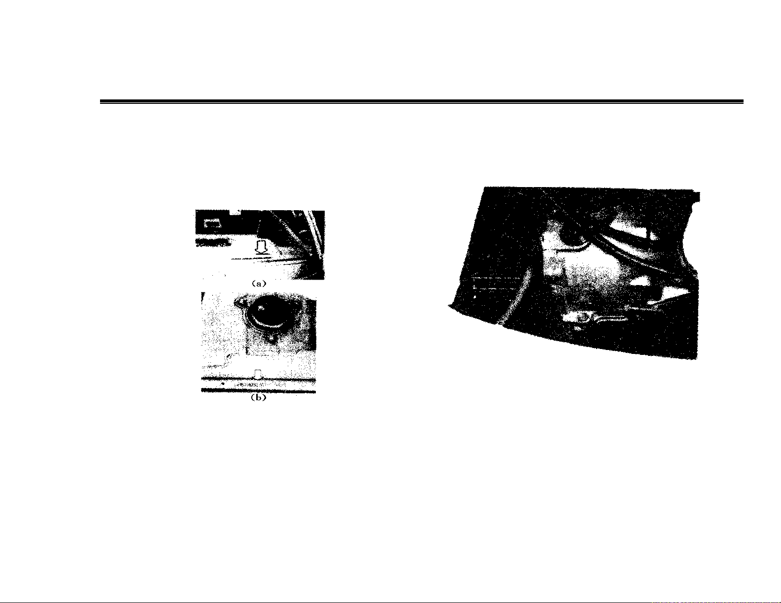
6. Replacement of engine coolant
Note: In order to avoid scald, when the temperature of engine and
radiator is high, do not remove radiator cap, at that time if removing
the radiator cap, coolant and vapor shall eject under the pressure
effect.
(1) After engine is cooled, remove radiator cap.
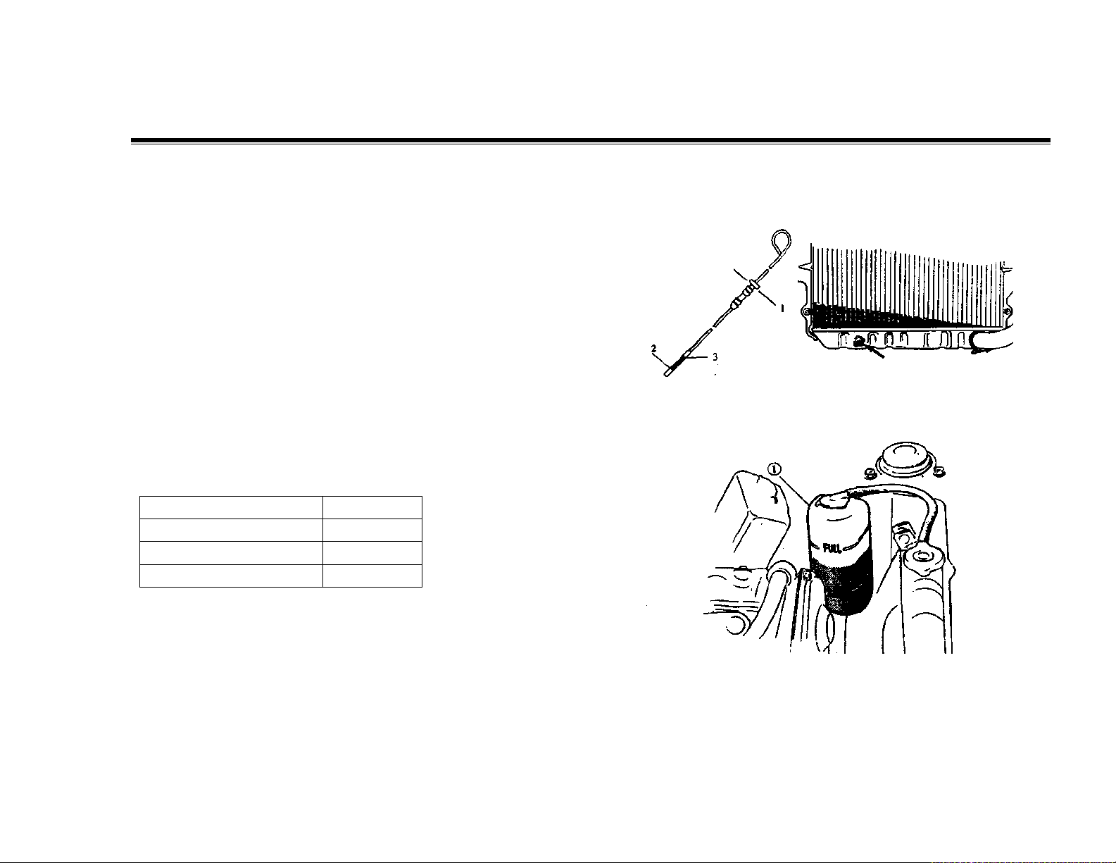
(2) Remove radiator discharge orifice cock to discharge coolant, as
shown in Fig. 1.4-6.
1.Reference line 2. Low level line 3. Full level line
(3) Dismount hydraulic accumulator ①, empty liquid. See Fig. 1.4-7.
Fig. 1.4-5 Fig. 1.4-6
Fig. 1.4-7
24

Chapter I. Whole Vehicle
Operation and Service Manual on VANTAGE TruckALL & VanGO Series
(4) Screw discharge orifice cock, and install the hydraulic
accumulator at the original position.
Fill up coolant into radiator, and run engine at idle speed, until affirm
that engine coolant pass through one large cycle at least, then stop
running engine. After temperature drops, fill up the radiator again,
cover the radiator cap and screw it.
(5) Pour coolant into hydraulic accumulator and make liquid level
reach to “FULL” mark
Coolant capacity table
Engine, radiator and heater 3.4L
Hydraulic accumulator 0.6L
Total 4.0L
7. Cooling system hose and joint
(1) Check visually the presence and absence of leakage or chap, break
of cooling system hose. Check whether they are damaged or not, and
also check the tightness of connecting clip.
(2) The hopes with leakage, chap, break or other damage shall be
replaced. At the same time the clip that cannot maintain appropriate
tightness should be also replaced.
8. Exhaust pipe and accessories
Note: In order to avoid scald, when the temperature of exhaust system
is still high, do not touch it. Any relevant service of exhaust system
should be done after the system is cooled.
When do regular service work or the vehicle is lifted due to other
service, check exhaust system according to the following steps:
(1) Check the presence and absence of da mage, aging and over
distortion of rubber parts.
(2) Check the presence and absence of leakage, connection looseness,
hollow and damage of exhaust system. If bolts or nuts are loose,
screw them to specified torque.
The tightening torque: exhaust pipe nut: 35-45N·m(3.5-4.5kg•m)
Exhaust pipe bolt: 35-50N·m(3.5-5.0kg•m)
(3) Check the presence and absence of damage, leakage, cracking,
looseness of the position near the body, and the condition that makes
exhaust infiltrate the inside body.
(4) Any bad cases must be resolved immediately.
(II) Ignition system
1. Ignition circuitry (secondary wire)
(1) Check whether secondary wire is broken, and the connection is firm
or not.
(2) Measure resistance value of secondary wire.
The resistance value of secondary wire: Standard---16 kΩ/m
Operation limit---20 kΩ/m
(3) Replace aged secondary wire.
Note: Check every secondary wires, to guarantee that their ends are
inserted firmly into joint elements. Any burned jointer must be replaced.
2. Distributor cap and distributor arm
(1) Check whether distributor cap is broken or not.
(2) Check whether center electrode and connector are abraded, the
position is shown in Fig. 1.4-8.
Fig. 1.4-8
25

(3) Check whether distributor arm is broken, and electrode is abraded.
(4) If you find the bad cases mentioned above, please repair or replace
them if necessary.
Note: If there is dust or dirt on the inside distributor, wipe up them
with soft cloth.
3. Replacement of spark plug
(1) Dismount secondary wire from spark plug. Note that the spark
plug cap (protective sleeve) on secondary wire should be held,
pull out secondary wire, as shown in Fig. 1.4-9.
Fig. 1.4-9
(2) Loosen spark plug with spark plug spanner, and remove it.
Note: New spark plugs which conform to specific calorific power
range and size must be replaced (refer to engine manual).
(3) Install new spark plug, and screw the spark plug to the specified
torque.
The tightening torque of spark plug : 20-30N·m(2.0-3.0kg·m).
(4) Aim secondary wire at spark plug, and insert it, do not push the
flexible wire part, push the protective sleeve part.
4. Ignition timing check
Check ignition timing to guarantee its correct set. If it does not conform
to the specified value, it should be regulated.
For relevant check and regulating steps, please refer to engine manual.
5. Distributor ignition advance unit
Check whether ignition advance unit operate normally. For relevant
check steps, please refer to engine manual.
(III) Fuel system
1. Clearing and replacement of air filter cartridge
(1) Dismount air filter cover.
(2) Take out filter cartridge from filter. bowl
(3) Clean the filter cartridge or replace new one. When cleaning the filter
cartridge, use compressed air to blow off dust from the inside filter
cartridge. See Fig. 1.4-10.
Fig. 1.4-9
26

Operation and Service Manual on VANTAGE TruckALL & VanGO Series
(4) Equip filter cartridge into air filter bowl.
Note: After the vehicle runs in dusty area, check whether filter
cartridge is full of dust, if it is, it must be cleaned.
(5) Cyclone duster
Dismount dust pocket from cyclone duster, and clear off the inside
dust pocket, as shown in Fig. 1.4-11.
Dust pocket Loosen Dust pocket
Screw Dust
Fig. 1.4-11
Throttle cable, choke cable and throttle shaft
Lubricate rotation position, and guarantee when choke pull button is
pulled, every parts of choke system operate smoothly.
3. Fuel tank, fuel pipeline and connector
(1) Check visually the presence and absence of oil leakage of fuel
pipeline and connector, check the presence and absence of hose chap
and break, at the same time check the tightness of all clips
The hose with break possibility must be replaced.
Chapter I. Whole Vehicle
(2) Check visually the gasket of fuel tank cap. If there are cases of
abrasion, break and distortion, replace the gasket.
4. Replacement of gasoline filter
Filter must be replaced regularly. The replacement method is as follows:
(1) Disconnect the inlet and outlet hoses of filter, and dismount the filter
from the vehicle.
(2) Install a new one in place, and connect the inlet and outlet hoses to
the filter.
Note: For gasoline filter for carburetor engine, the upper side is for
connecting the outlet tube and the lower part is for connecting inlet tube.
See Fig. 1.4-12
Fig. 1.4-12
1. Inlet 2. Outlet
5. Engine idle and idle mixture
Check idle and idle mixture, and regulate if necessary.
27

Chapter I. Whole Vehicle
Operation and Service Manual on VANTAGE TruckALL & VanGO Series
For the check and regulation steps of idle and idle mixture, refer to
operation manual on engine.
(IV) Exhaust pollution control system
Crankcase ventilation hose and connector
Check the presence and absence of leakage and break of crankcase
ventilation hose. If there is any bad case, repair or replace it. Check
hose connector to guarantee its tightness and firmness.
2. PCV (forced ventilation of crankcase) valve check
(1) Dismount the hose connecting tee joint to PCV valve.
(2) Start engine. Engine shall run at idle; press one end of the hose
with thumb to check the negative pressure in the hose. If the hand is
gripped by the hose, showing that PCV valve is in good state, as
shown in Fig. 1.4-13.
Fig. 1.4-13
(2) Stop engine running, and connect the hose on the tee joint.
3. Fuel evaporation control system
1) Check the presence and absence of crack, damage or over bending of
the hose, check whether all clips are damaged.
2) If you find any bad cases, repair and replace them.
3) Refer to engine manual to check the vapor channel of activated
charcoal container.
(V) Electric equipment
1. Lamplight
Check whether all lamps work normally, if is necessary, repair or replace
relevant parts.
2. Harness and connector
(1) Check whether all wires are damaged, connectors are connected well.
(2) All clamps and clips must clam harness firmly.
(3) The wires in bad state should be replaced.
(VI) Chassis and body
1. Check of clutch pedal free travel
(1) Check clutch pedal free travel.
Free travel: 20-30mm.
(2) Daub grease on hook and connect positions of clutch stay.
2. Brake disc, brake tongs brake drum and brake shoe
(1) Brake disc and brake tongs
Dismount wheel and clamp, but do not make brake hose separate clamp.
2) Check the presence and absence of over abrasion, damage and
distortion of brake tongs and brake disc of front disc brake. Replace
relevant parts if necessary.
When reinstalling, it should be noted that bolts are screwed to the
specified torque.
(4) Brake drum and brake shoe
1) Dismount wheel and brake shoe
28

Operation and Service Manual on VANTAGE TruckALL & VanGO Series
2) Under the condition that wheels and brake drum are dismounted,
check whether brake drum and friction facing is over-abraded,
whether brake wheel cylinder leaks oil. Replace relevant parts if
necessary.
3. Brake line check
Check whether brake hose and oil pipe are cla mped correctly, there
are oil leakage, crack, gall and other da mage. Replace relevant parts if
necessary.
Note: After replacing any brake line or hose, be sure to discharge air
in the system.
4. Check and replacement of brake fluid
(1) Check whether there is leaked brake fluid around brake master
cylinder and brake oil tank. If there is oil leakage, it is necessary to
maintain.
(2) Check brake fluid level. If brake fluid level is lower than the
lowest fluid level, it is necessary to compensate brake fluid.
Note: The brake system of the vehicle has been fill composite type
brake fluid in the factory, so do not pour other types of fluid or mix
other types of fluid. Do not use old or used brake fluid, and the brake
fluid taken from unsealed container, either.
(3) Change brake fluid every two years. The steps to change brake
fluid are: discharge the fluid remaining in brake system completely,
then pour new brake fluid into the system, and discharge the air in the
system.
For exhaust description, please refer to Section 7 of Chapter 3.
5.Brake pedal
Check brake pedal free travel.
For check steps, please refer to Section 7 of Chapter 3.
6. Parking brake lever and stay
(1) Check whether every tooth crest of ratchet plate is abraded or
damaged. If there is abrasion or damage case, the abraded or damaged
ones must be replaced.
Chapter I. Whole Vehicle
(2) Pull up parking brake lever with single hand completely, to make
brake act fully, while pulling brake lever, listen to the total tooth gap
quantity that crawl lever passing carefully (each “chattering”
sound stands for passing one tooth). If passed tooth gap quantity exceeds
8, it is necessary to regulate parking brake stay.
Parking brake lever travel: within 3-8 ratchets (when brake lever pull up
in 20 kg force).
For travel measurement and parking brake regulation, refer to Section 7
of Chapter 3.
(3) Parking brake stay
Check whether brake stay is damaged, moves smoothly, if the stay
shows worsening, it should be replaced.
7. Tire check and transposition
(1) Check whether tire is abraded unevenly or over abraded. If there is
such case, please replace it.
(1) Check charging pressure of each tire, and regulate the pressure to
the specified value if necessary.
Note: Tire charging pressure must be checked in the state of tire cooling.
The specified tire charging pressure can be consulted from tire logo and
this manual.
(3) Tire transposition use
About the details of the above-mentioned steps, please refer to Section 8
of Chapter 3.
8. Wheel and wheel nut
(1) Wheel felly
Check whether each wheel felly has drop, distortion and crack. The
wheel felly damaged badly should be replaced.
(2) Wheel bearing
29

Chapter I. Whole Vehicle
Operation and Service Manual on VANTAGE TruckALL & VanGO Series
1) Check whether front wheel bearing is abraded, caught or loose.
2) Check whether rear wheel bearing is abraded, caught or loose.
(3) Wheel nut
Check whether wheel nut is screwed, and screw is screwed to the
specified torque if necessary. See Fig. 1.4-14.
The screwing torque of wheel nut: 50-80 N·m(5.0-8.0kg·m).
Fig. 1.4-14
9. Absorber
(1) Check the presence and absence of absorber oil leakage, hollow
and other damage on sleeve; and of break and aging of upper pivot
rubber lining, and rear absorber bush.
(2) Part replacement is determined according to the above-mentioned
check result.
10. Transmission shaft
(1) Check whether universal joint and spline of transmission shaft is
loose. If you hear “chattering” sound, damaged parts should be replaced.
See Fig. 1.4-15
Fig. 1.4-15
(2) Check the tightness of transmission shaft bolts, and screw them if
necessary
The tightening torque: 18-28 N·m (1.8-2.8 kg·m)
11. Check and replacement of gear oil
(1) Check
1) Check the presence and absence of oil leakage of transmission case
and rear axle shell. If there is, repair oil leakage position.
2) When checking oil level, guarantee that the oil level is horizontal.
3) Dismount the filler plug. When inserting fingers into the filler, you
can know the oil level approximately. If the oil level is close to the filler,
showing that the oil filling is proper, as shown in Fig. 1.4-16.
30

Operation and Service Manual on VANTAGE TruckALL & VanGO Series
Fig. 1.4-16
1. Transmission filler 2. Transmission oil
If gear oil is deficient, fill the specified brand gear oil to the
above-mentioned oil level.
4) Dismount rear axle filler plug. The oil level can be checked from
the filler, the method is the same as the above, gear is deficient, please
fill some.
(2) Oil replacement
Note: Before oil replacement, first check the presence and absence of
oil leakage. If there is oil leakage, it is necessary to repair first , then
fill specified amount of new oil.
Oil capacity: 1.3L
Oil brand: 80W/90(GB13985-92) GL-5(or GL-4) grade gear oil or
18# hyperbola gear oil.
2) Rear axle
Oil capacity: 1.3L
Oil brand: 80W/90(GB13985-92) hyperbola gear oil.
Chapter I. Whole Vehicle
Fig. 1.4-17
1. Filler plug 2. Discharging oil screw plug
Fig. 1.4-18
1. Discharging oil screw plugs 2. Filler plug
31

Chapter I. Whole Vehicle
Operation and Service Manual on VANTAGE TruckALL & VanGO Series
12. Suspension
(1) Check whether the presence and absence of abrasion and break of
spring, if there is over abrasion and break case, the spring should be
replaced.
(2) Check the tightness of bolt and nut, and screw them to the
specified value if necessary.
13. Steering system
(1) Check the steering wheel free travel and looseness, when
checking, put the vehicle on flat ground, and the wheels face right
ahead.
Steering wheel free travel: 0-30mm
(2) Check whether the joint of steering shaft is loose or damaged. If
there is loose or da mage case, replace relevant parts.
(3) Check the tightness of bolts and nuts, and screw them if necessary.
(4) Check the presence and absence of break and other damage of
dust cap of steering rack, if there is, replace them.
(5) Check whether dust cap of globular pin is damaged, if it is
damaged, replaces it with a new one.
(6) Check front wheel positioning, if there is change, regulate it to the
specified value.
(7) While the vehicle is running, abnormal resistance and chattering
should not occur on steering wheel absolutely, if occurring, it must be
repaired.
14. Lubrication of door hinge
Wipe dirt, and daub a thin layer of engine oil, open and close the door
many times to guarantee the engine oil flow into axial play efficiently.
(VII) Test driving
After the regular check operation of all times mentioned above is
finished, road test shall be done in safe area.
Note: When doing the following road test, it is necessary to select a safe
area without passers-by and vehicle running, to avoid accident
occurrence.
1. Engine start
Check engine-starting state to prepare for test.
2. Clutch
Check the following items:
! When treading on clutch pedal, the clutch should separate
thoroughly
! Disengage the pedal and accelerate, the clutch dose not skid,
and engage smoothly.
! Clutch itself has not abnormal sound or other abnormality.
3. Shift lever
Check whether gearshift is easy, is not caught and the shift performance
of all gears is good, not shift out automatically when shift lever puts into
all gears.
4. Brake
(1) Traveling brake
When driving to tread on brake pedal, check the following items:
! Braking action of brake is good.
! There is no noise from the brake.
! The braking force acted on all wheels is uniform.
(2) Parking brake
Check parking brake, when pulling up parking brake lever to make the
brake act fully, guarantee that the vehicle does not skid when parking on
20% slope road.
5. Steering unit
Check steering wheel, there should not have the feeling of catching,
chattering, too tight to turn in driving.
6. Engine
32

Operation and Service Manual on VANTAGE TruckALL & VanGO Series
Chapter I. Whole Vehicle
• Check the engine and ensure smooth operation at different rpm
• Check the engine and ensure no abnormalities during operation
7. Body, wheel and power train
Check the body, wheels and power train, there shall be no abnormal
noise, vibration and other conditions.
8. Instruments
Check the speedometer, odometer, fuel gauge and water
thermometer, and ensure precision of their work.
9. Warning light of oil pressure, charging indication light, warning
light of brake fluid level and warning light of engine failure
Check whether the lights turn off or not during engine running. If
any one of the lights does not turn off, it shows that the corresponding
part goes wrong and need to be serviced.
10. Seat belt
Seat belt can be tightly fixed in the event of emergency braking.
33

Chapter II. Engine
Operation and Service Manual on VANTAGE TruckALL & VanGO Series
Chapter II. Engine
Note: The part of engine will mainly focus on service manual. The
following will only illustrate the aspects not referred in the previous
part.
Section 1 Carburetor Engine Accessories
I. Oil supply system of carburetor engine
(I) Components of fuel supply system
Fuel supply system consists of fuel tank, fuel pipe, fuel filter,
fuel pump, intake system and exhaust emission control devices etc.
Please refer to Fig. 2.1-1.
1. Operational principle of oil supply system
Fig. 2.1-1 operational principle of oil supply system
1. Fuel tank 2. Fuel filter 3. Fuel pump 4. Intake pipe 5. Oil
return pipe 6. Exhalant pipe 7. Carbon tank 8. Vacuum tube 9.
Carburetor 10. Desorption pipe 11. Air filter 12. Dirt collector
13. Cool air pipe 14. Hot air pipe 15. Intake valve 16. Gas-oil
separator
When the ignition switch is in the position of ON, the oil pump begins to
pump and the oil is drawn from the oil tank. After being filtered by the
oil filter, the filtered oil flows to the carburetor through oil pump and
intake pipe. In the event that there is much oil in the float chamber of
carburetor, the oil returns to the oil pump through oil return pipe.
2. Oil tank
(1) Oil tank structure
Oil tank is seamed from sheet steel stampings. A oil volume sensor is
attached to the upper center. A pouring orifice is seamed on the side, and
an oil draining plug is fixed on the bottom which is used to drain
deposited water and particles in the oil tank.
(2) Assembly and disassembly of oil tank
The oil tank is connected to oil tank support bolts by means of four holes
in the tank body. After disassembling and draining the oil tank, the
pouring rubber hose shall be taken down first, and then the wirings of oil
volume sensor shall be disassembled, and the last step is to release or
twist out the clamping collars of the oil pipe and return oil pipe.
3. Oil filter
Oil filter is barrel shaped and is cemented together by pressing plastic
barrel body and barrel cover. Filter element is fixed in the interior, an oil
feeding joint is fixed on the barrel body, and an oil out joint is fixed on
the barrel cover. The oil filter cannot be disassembled, so a new filter
shall be exchanged after driving 40000km (if the oil quality is not in the
standard level, the specified mileage shall be appropriately shortened).
4. Oil pump
Power oil pump is attached to the right frame side rail. Please refer to
Fig. 2.1-2.
(1) Power stroke
When the ignition switch is turned on, the electrical current is flowed to
the coil (3) through contact switch and excited the wiring. The exciting
coil (3) attracts plunger (4) and makes the pull rod (12) and diaphragm
(7) move upward and downward. Thus the lower volume is increased
and oil is drawn to the oil chamber (11) through oil valve (10).
Meanwhile, as the pull rod moves upward and makes the upper caliper
trigger the spring seat, the position of springs (15) is
34

Operation and Service Manual on VANTAGE TruckALL & VanGO Series
Chapter II. Engine
Therefore changed resulting cut off of contact switch (2) and
electrical current and disposal of wiring magnetism as well. The
diaphragm and pull rod are pushed downward under the force of
gravity and elasticity, so oil in the oil chamber can push the oil valve
and flow out of the oil pipe, the upper contact can be again connected.
The process is reciprocated and pumps quantitative oil.
(1) Assembly and disassembly check
1) When failures occur in the power oil pump, the oil pipe shall be
checked to see whether there exist breakage, the pump body shall be
checked to ensure no leakage, and the diaphragm shall also be
checked to see whether there exist cracks. Leakage shall be disposed
and the cracking part shall be exchange.
2) The contact point shall be checked to ensure no ablation. If occurs,
the oil stone shall be used to smooth it and make the close contact.
Fig.2.1-2 sketch of power pump structure
1. Contact switch 2. Contact point 3. Coil 4. Plunger 5. Pump
cover 6. Spring 7. Diaphragm 8. Oil out valve 9. Oil valve
spring 10. Oil feeding valve 11. Oil chamber 12. Pull rod 13.
Caliper 14. Spring seat 15. Displacement spring
Fig. 2.1-3 Check of the power pump flow capacity
1. Battery 2. Black/ white wiring 3. Black wiring 4. Oil pump
5. Kerosene H=50cm
3) After final completion, check the power pump flow capacity
according to the method referred in Fig. 2.1-3, and the flow capacity
shall be more than 500ml/min.
Oil Pump (mechanical)
(1) Introduction
The pump and diaphragm assembly in the mechanical oil pump pumps
petrol into carburetor float chamber. The pump and diaphragm is driven
by the eccentric wheel placed on the camshaft of the engine valve
mechanism, the pump rod is tightly pressed on the eccentric wheel and
makes the pump and diaphragm move upward and downward. Please
refer to Fig. 2.1-4.
35

Chapter II. Engine
Oil Pump Specifications
Discharge pressure 24.5-24.3kPa
Pump capacity 1.3L/min (200r/min)
Pump diaphragm
Fig 2.1-4
Operation and Service Manual on VANTAGE TruckALL & VanGO Series
Pump rod
(2) Disassembly
As indicated in Fig. 2.1-5, the upper and lower joints shall be marked
①, to recognize the angle position of upper body ② and lower body
③. Only if angle relation is ensured, the oil circuit can be connected.
Fig. 2.1-5
(3) Check
1) Leakage of fuel pump.
2) Breakage of oil hose.
3) Tightness of all bolts.
4) The conditions of cracking and da maging of pump diaphragm
after disassembly of the oil pump.
36

Operation and Service Manual on VANTAGE TruckALL & VanGO Series
Chapter II. Engine
Fig. 2.1-6
(4) Assembly
1) Put the pump diaphragm on the pump rod as indicated in Fig.
2.1.-6, and then insert the pump stay into the pump rod. Swivel it
90º at the same time of pushing the pump rod, and the pump
diaphragm is attached to the pump rod④ in this way.
Note: When the pump diaphragm is swiveled 90º and attached to
the pump rod, the pump diaphragm tongue piece shall be on the
position of pump rod ⑤. Please refer to 2.1-6.
2) Based on the relative positions of upper body and lower body
which are marked before disassembly, screw eight screws.
3) Push pump rod ④ to the extreme position 4 or 5 times, and
make the pump diaphragm center and pump center can be matched.
Please refer to 2.1-7
4) Finally, tighten the eight screws.
Fig. 2.1-7
(II) Intake System
1. Intake system is composed of cool air intake pipe, hot air pipe,
intake valve, dirt collector and air filter etc.
2. Operational principle of intake system
The system applies dual air filtering system. As is shown in Fig.2.1-1,
the switch handle on the intake valve 15 shall be turned to the side of
“summer” in summer, and the fresh air will flow into the dirt collector 12
through cool air pipe 13 from the vehicle front side, and after being
dusted, the dusted air flows into the air filter 11 through escape pipe.
While, the switch handle on the intake valve 15 shall be turned to the
summer of “winter” in winter, and the warmed up air will flow into dirt
collector 12 through hot air pipe 14 from the vehicle front side, and after
being dusted, the dusted air flows into the air filter 11 through escape
pipe.
37

Chapter II. Engine
d
Operation and Service Manual on VANTAGE TruckALL & VanGO Series
The thir
chamber
The first
chamber
Outlet
Inlet
The
second
chamber
Fig. 2.1-8
3. Dirt collector
Dirt collector is installed on the front of the air filter inlet, and the
purpose is to filter the air which flows into the air filter.
(1) Operational principle
With the running of the engine, the air is drawn into the first chamber of
the dirt collector, and then flows into the second chamber through
windmill air vane shaped diaphragm orifice ① which will exert rotary
action on the air. The centrifugal force generated by rotary air current
spread the dirt around, and the dirt will hit the internal wall of the second
chamber and fall into the cup ② surrounding the wall while the dusted
air is drawn into the air filter through the third chamber. Please refer to
2.1-8.
Dirt
Release
Tighten
Fig. 2.1-9 Cleaning of dirt collector
38

Operation and Service Manual on VANTAGE TruckALL & VanGO Series
Chapter II. Engine
(2) Daily cleaning
Clean dirt collecting cup monthly. As is shown in Fig. 2.1-9, disassemble dirt
collecting cup from the dirt collector, dump the dirt and reassemble it to the
previous position.
4. Exhaust emission control device
In order to prevent the petrol vapor from flowing into the air and reduce the
pollution to the air, the control to oil vaporization include the following two parts:
the first is to seal oil pump and increase the internal pressure of oil tank to reduce
the original vaporized volume; the second is to store and intake the vaporized
volume after surpassing certain pressure, and send them to the intake pipe to burn
when the engine running.
Exhaust emission control device include carbon tank, oil-gas separator, oil tank
cover with single directional valve, exhalant pipe, vacuum pipe, desorption pipe
etc. Please refer to Fig. 2.1-1.
The operational principle of the system is that : intake the oil vapor from the oil
tank by using the excellent quality of absorption and desorption of active carbon.
When the engine is on normal operation, make desorption to the oil vapor stored
in the active carbon by applying the vacuum degree of the intake system and
make the active carbon restore its ability of storing and absorbing.
The power stroke of the system is that: with the change of environmental
temperature and pressure, the oil vapor in the oil tank exhausted from vapor
escape port will be condensed through oil-gas separator, the condensed liquefied
oil returns to the oil tank and the vaporized oil flow into the active carbon to be
stored through the double directional valve of the carbon tank. When the engine
normally runs, vacuum is created in the engine carburetor, the fresh air is drawn
through the air port of carbon tank under the function of carburetor vacuum.
When the fresh air passes the carbon tank, it takes the oil vapor stored in the
active carbon to the engine carburetor and then flow into the combustion chamber
together with intake combustible mixture to burn. When vacuum is created as a
result of environmental temperature falling and oil consumption, the fresh air will
be drawn from the air port of the carbon tank under the function of oil tank
vacuum and flows into the oil tank through carbon tank and oil-gas separator to
release the vacuum existed in the oil tank, and thus protecting the oil tank to
ensure the normal operation of the engine.
II. Exhaust System
Exhaust system is made up of intake pipe, muffler and relevant
accessories.
(I) Exhaust muffler
1. Muffler structure
The purpose of the exhaust muffler is to reduce the impulse of the
exhaust current and therefore reduce the exhaust noise.
The muffler welding assembly applies dual rate muffling, the first rate
adopts extending muffling and the second rate adopts expanding
muffling.
Fig. 2.1-10
1. Sealing gasket 2. Intake pipe 3. Bolt 4. Spring 5. Sealing coil
6. Muffler 7. Cushion slab
39

Chapter II. Engine
As the exhaust manifold of engine applies compound exhausting, the
exhaust system can be divided into two parts, namely intake pipe and
muffler welding assembly. The intake pipe cooperates with the engine
to make compound exhausting, and combines the two pipes into one
pipe.
2. Installation and function
The intake pipe is connected to the engine exhaust manifold, and
sealed by sealing gasket and then bolted together. The ball shaped
sealing gasket to seal the intake pipe and muffler welding assembly,
the cone shaped springs and bolts are used to tighten them. Rubber
pad is used to connected the muffler welding assembly and frame rail.
After connecting the intake pipe and muffler welding assembling, host
them to the frame rail and then turn it to the suitable angle to make
muffler tailpipe not interfere with other parts, the last step is to tighten
all the bolts. Refer to 2.1-10.
3. Maintenance and service
The exhaust system shall be checked when a vehicle drives every
20,000 kilometers.
The check includes the following: whether there exists damages of
muffler sealing gasket and whether there exists damages of intake
pipe and muffler welding assembly, and if any failure occurs, the part
shall be exchanged; whether the joint point of intake pipe and engine
releases, if occurs, it shall be tightened.
Operation and Service Manual on VANTAGE TruckALL & VanGO Series
I. UAES system (ally electronics)
(I) Oil supply system
1. Electric controller 2. Water temperature sensor 3.Oil nozzle
4. Oil guide 5. Carbon tank magneto valve 6. Return oil valve
7. Induction manifold 8. Carbon tank 9.oil filters 10. Fuel tank
11. Fuel pump 12. Oil-gas separator 13. Oil pressure regulator
14. Air intake temperature and pressure sensor 15. Step motor
16. Restrictor position sensor 17. Air filter 18. Dirt collector
19. Intake pipe 20. Restrictor valve body
40
Section 2 Electro Engine Series of Accessories
Fig. 2.1-1 Schematic Diagram of UAES Oil Supply System

Operation and Service Manual on VANTAGE TruckALL & VanGO Series
Engine control system immediately supply power to engine electric
controller after the ignition switch turn to the position of “ON” (do
not start the engine). The electric controller then connects fuel pump
relay and the power source is switched on. 300kPa pressure will be
produced in the fuel pipe after filtered by the oil filter and then send
to the oil guide rail and oil guide rail distributor on the intake
manifold. After the start switch is switched on, the electric controller
turns on the oil pump relay and oil pump power supply is switched
on, then the electric controller controls the fuel injector of every
cylinder intake pipe to inject oil regularly based on ignition signal.
(As to the operational principle, please refer to engine service
manual).
The injection order of oil supply system is: the four nozzles injects
one by one according to the sequence of one, two, three, four.
1. Fuel pump (type: D580CN1009)
The fuel pump and its support assembly consist of the following
parts: fuel pump, oil level sensor, flange with electric and oil circuit
joint etc. (Please refer to Fig. 2.2-2).
Chapter II. Engine
Installation method
Electric fuel pump is submersible pump and the pump support
assembly is installed in the oil tank. The flange is sealed to the flange
which passes rubber sealing rings and the relevant parts.
(1) Oil circuit joint
The joint of intake pipe and return oil pipe outside the flange must
be fixed and reliable to ensure the system to have no leakage under the
pressure of 300kPa.
(2) Technical specifications
Operational voltage 6-15V DC(according to the
vehicle power supply system)
rated operational voltage:12V
Systematic pressure 300kPa
Operational temperature range -40℃——+80℃
allowable operational agent high quality lead free petrol
Durability more than 100000 kilometers on
1. Harness assembly 2. Wire clip 3.
Spring 4. Guide rod 5. Pressure hose
6. Oil pump 7. Oil pump bracket 8. Oil
reservoir 9. Flange 10. Caliper 11.
Fluid level sensor assembly 12. Spring
ring 13. Holding ring 14. Oil filter
Fig.2.2-2 Fuel Pump and Support Assembly
which numbered over 90
the condition of normal running
and satisfying the operational agent
and without changing the
installation method
41

Chapter II. Engine
Note:
• As the demand for electric vehicle oil supply pressure is quite high,
the rubber pipe and clip must be able to ensure the pressure of more
than 300kPa. Therefore, the rubber pipe and clip cannot be substituted
by ordinary part, otherwise the leakage will occur in the pipe. More
seriously, a fire hazard will also occur.
• The operational requirement for the fuel pump is to have enough
fuel oil in the fuel tank. If there is not enough fuel oil in the fuel tank,
the fuel pump may be burned to be damaged by its own poor cooling.
Therefore, when the engine or the vehicle is running, enough quantity
of fuel oil must be ensured in the fuel tank.
• When disassembles the fuel pump and support assembly, the
pressure of fuel oil pipe must be firstly released in order to avoid hurt
to people.
2. Fuel filter
The fuel filter is barrel shaped and cannot be disassembled. The filter
element is installed in the interior. A new fuel filter shall be exchange
every 10000 kilometers’ driving.
Note: As the demand for the bursting pressure endured by the electric
vehicle used fuel filter is quite high (no less than 16kg), the filter
cannot be replaced with carburetor vehicle used fuel filter.
3. Emission control device
As the operational principle of the device, please refer to Fig.2.2-1.
With the environmental temperature and pressure changes, the petrol
vapor in the petrol tank exhausted from the airport will be condensed
through oil-gas separator. The condensed liquefied petrol is returned
to the petrol tank and the vaporized petr ol is stored in the active
carbon tank through carbon tank dual directional valve. When the
engine is in normal running, the electric controller module controls
carbon tank control valve and drive and adjust the volume of
desorption air current.
Operation and Service Manual on VANTAGE TruckALL & VanGO Series
The operational principle of the carbon tank is as the following: The
vacuum generated in the engine intake system makes the fresh air be
drawn from the carbon tank air port. When passing the carbon tank, it
takes the petrol vapor in the carbon tank to the engine intake system, and
then sent to the combustion chamber together with intake mixture. In the
event that vacuum is created as a result of environmental temperature
falling or petrol consumption, the fresh air will be drawn from the air
port of the carbon tank under the function of oil tank vacuum and flows
into the oil tank through active carbon tank, dual directional valve,
oil-gas separator and air port to release the vacuum existed in the oil
tank, and thus protecting the oil tank to ensure the normal operation of
the engine.
(II) Intake system
As the operational principle of the intake system, please refer to
Fig.2.2-1.
The electric controller module measures intake temperature, pressure,
engine rpm, phase signal through intake temperature and pressure sensor
installed on the intake system, cooling fluid temperature sensor and Hoor
sensor located in the ignition coil. Meanwhile, the system can precisely
calculate the actual intake volume of the engine based on the coolant
fluid temperature input signal when the engine is regularly running.
When idling, the electric controller controls the intake volume by
controlling the section area of idling step motor air adjusting valve.
Note: When the electric controller is power off or the battery is
exchanged, again learning on the step motor shall be made when
restarting the engine.
The steps are as follows: turn the ignition switch to the position of “ON”
(do not start the engine), and restart the engine after keeping 10 seconds.
(III) Exhaust system
The exhaust system is composed of tri-effective catalytic converter
welding assembly, muffler welding assembly and joint components.
Please refer to Fig.2.2-3.
1. Catalytic converter
(1) The function of catalytic converter is: convert the harmful exhausts
(HC, CO, NO
, N2) to reduce air pollution.
CO
2
42
) from the engine tailpipe into harmless exhausts (H2O,
x

Operation and Service Manual on VANTAGE TruckALL & VanGO Series
Chapter II. Engine
Fig. 2.2-3 Structure Chart of Exhaust System
1. Tri-effective catalytic converter welding assembly 2. Muffler
welding assembly 3. Joint component
(2) Catalytic converter structure
Catalytic converter includes a piece of ceramics carrier wrapped
by backing strap and inserted in a section of tube shaped body case.
The hole of the carrier is painted with catalyst coating (Pt, PD, Rh).
Note:
• The fuel oil used must be of high quality lead free petrol (over
RON90, and lead volume is less than 0.005L etc), as leaded petrol
will damage tri-effective catalytic converter and the components of
electric control system as hereafter will interfere with the normal
operation of the parts.
• The tri-effective catalytic converter shall not be stricken and
strongly vibrated, as the interior ceramics carrier may be broken to
block the exhaust system.
• When a fire occurs, namely the engine does not run regularly after
start, the engine power significantly decreases or other abnormal
phenomenon which indicates there exists failures in the ignition system,
please contact with service station quickly. If necessary, low speed and
short distance driving can be made at low engine rpm.
• Try to avoid frequently cold start and long time run the engine during
the starting period (fuel oil is injected to the cylinder during the starting
period, and will be exhausted to the tri-effective catalytic converter
without being burned which will cause damages to the converter).
• When the oil in the tank is nearly used up, irregular oil supply will
result in the damage to the tri-effective catalytic converter.
• Do not apply the method of pulling or pushing to start the engine (the
fuel oil without being burned will flow into the tri-effective catalytic
converter which will cause damages to the converter).
Note For Maintenance And Service
• Maintenance shall be made regularly to ensure the normal operation of
the electric control system. If any abnormal condition occurs, it shall be
timely repaired to ensure exhaust level of vehicle and long life time of
the tri-effective catalytic converter.
• The exhaust pipe sealing gasket must be replaced when replacing a
new component.
• No foreign particles shall be fallen into the tri-effective catalytic
converter during assembly. Otherwise, the tri-effective catalytic will be
damaged.
• Check whether there exists gas leakage or other abnormal noises of
exhaust system joints and check whether the electric system works
normally after the normal running of the engine.
II. DELPHI system
(1) Oil supply system
When the ignition switch is switched on, the engine control system
immediately supplies power to the engine electric control module. In the
event that the engine start switch is turned on, once the system detects
the first impulse signal of the crankshaft rotation, the electric controller
connects fuel pump relay. Power source of the fuel pump is switched on
and the fuel oil is pumped and pressed by electric oil pump from the oil
pump, then the fuel oil is sent to the fuel oil guide rail and guide rail
distributor above the engine to make the fuel injector installed on each
cylinder regularly inject after filtered by the fuel filter.
43

Chapter II. Engine
Operation and Service Manual on VANTAGE TruckALL & VanGO Series
The injection order shall be grouped injection: cylinder 1 and 4 are
grouped together, and cylinder 2 and 3 are grouped together.
1. Fuel pump (type: DELPHI25330569)
As to the fuel pump and support assembly components, please refer to
UAES system.
(1) Installation method
Electric fuel pump is submersible pump and the pump support
assembly is installed in the oil tank. The flange is sealed to the flange
through rubber sealing rings and oil tank flanges.
Fig.2.2-4 Schematic Diagram of Fuel Supply System
1. Electric controller 2. Oil nozzle 3. Fuel oil pressure adjustor
4. Crankshaft position sensor 5. Carbon tank magneto valve 6.
Return oil pipe 7. Induction manifold 8. Carbon tank 9. Fuel
filter 10. Fuel tank 11. Fuel pump 12. Fluid-gas separator 13.
Oil guide 14. Water temperature sensor 15. Intake pressure sensor
16. Step motor 17. Restrictor position sensor 18. Air filter
19. Dirt collector 20. Intake pipe 21. Restrictor valve body
22. Intake temperature sensor
(2) Technical specifications
Operational voltage 6-15V DC(according to the vehicle
power supply system)
Rated operational voltage:12V
Systematic pressure 300kPa
Operational temperature range -40℃——+80℃
Allowable operational agent high quality lead free petrol (over
RON90, and lead volume is less
than 0.005g/L)
Durability more than 100000 kilometers on
the condition of normal running
and satisfying the operational agent
and without changing the
installation method
Please refer to UAES system to see the notes.
2. As to the fuel filter, please refer to UAES system.
(II) Intake system
As to the schematic diagram of the intake system, please refer to Fig.
2.2-4.
The engine electric controller precisely measures the engine rpm and
various input signals through intake temperature sensor (MAT) installed
on the intake system, coolant agent temperature sensor (MAP) and
crankshaft position sensor (CPS) located on the transmission flywheel
cover. Meanwhile, the system exactly meters the actual intake volume of
the engine based on the input signals of the coolant agent temperature
sensor when the engine is on real time running. When idling, the electric
controller controls the intake volume by controlling the section area of
idling step motor air adjusting valve.
(III) Exhaust system
Exhaust system is composed of tri-effective catalytic converter welding
assembly, muffler welding assembly and joint component. Please refer to
Fig.2.2-5.
Please refer to UAES system to see the notes.
44

Operation and Service Manual on VANTAGE TruckALL & VanGO Series
Chapter II. Engine
Fig.2.2-5 Structure Chart of Exhaust System
1.Tri-effective catalytic converter welding assembly
2. Muffler welding assembly 3. Joint component
45

Chapter III. Chassis
h
p
Operation and Service Manual on VANTAGE TruckALL & VanGO Series
Chapter III. Chassis
Section 1 Clutch
I. Introduction
Clutch in the vehicle is single, dry, diaphragm spring clutch.
Diaphragm spring outer side is a whole body, inner rings have some
center pointing release fingers. The friction pad of the clutch is
installed on the transmission input shaft through splines. Four torsion
buffer springs are attached to the clutch friction pad. Diaphragm
springs are fixed to the clutch pressure plate by using rivets which are
taken as the support point of diaphragm springs.
Flywheel
Crankshaft
Clutch plate
Clutc
Fig.3.1-1a
ressure plate
Transmission input shaft
Clutch release
bearing
When the clutch is jointed, diaphragm spring outer rings are tightly
presses on the pressure plate which tightly presses the friction pad on the
flywheel.
When the clutch pedal is pressed, the release fork push the releasing
bearing to move left, and release bearing push diaphragm spring inner
ring release finger. Diaphragm springs make the spring outer ring move
right based on rivet and drive the pressure plate separate from the
friction pad. The clutch thus on the separation condition at the same
time, and thus the engine power is cut off.
This type of clutch is of simple structure, complete separation, excellent
heat emission, compact size, and need not to be adjusted.
Fig.3.1-1b Clutch
1. Clutch friction pad 2. Clutch pressure plate 3. Spring washer
4. Clutch bolt 5. Clutch release bearing 6. Clutch release pin
7. Liner 8. Clutch release shaft 9. Return spring 10. Sizing bolt
11. Clutch release pipe
46

Operation and Service Manual on VANTAGE TruckALL & VanGO Series
II. Disassembly
The prerequisite for disassembling the clutch is that the transmission
has been disassembled in the correct order.
The disassembly procedure is as the following:
① Disassemble the six bolts used to tighten the clutch, and then take
the clutch pressure plate and clutch friction pad out.
② Disassemble the clutch release bearing from the front of the
transmission shaft.
③ Disassemble the flywheel.
④ Disassemble the transmission input shaft side bearing from the
flywheel.
III. Examine the components
1. Wearing of the clutch friction pad
Measure the hollow depth of each rivet head, namely the distance
between rivet head and friction lining surface to check the wearing
condition of each friction lining. If the hollow depth of any hole has
reached to the wearing limit, a new clutch friction pad assembly shall
be exchanged.
Hollow depth
of rivet head
Standard Operating limit
1.2mm 0.5mm
2. Fit clearance of clutch friction pad splines
Rotate the clutch friction pad installed at the transmission input shaft
to check the spines clearance. If the clearance exceeds the operating
limit, a new clutch friction pa d assembly shall be exchanged. The
clearance means the displacement number on the circumference
measured by using micrometer gauge.
Fit clearance of
splines
Operating limit
0.8mm
Chapter III. Chassis
3. Clutch pressure plate
Check the friction spring rivet of the clutch pressure plate to find
whether there exists release. If the rivet releases or begins to release, that
is the clutch pressure plate produces “clatter” noise when the clutch
pedal is pressed, a new clutch pressure plate assembly shall be
exchanged.
Check the wearing condition of the joint point between diaphragm spring
release fingers and clutch release bearing. If the condition is quite
serious, a new clutch pressure plate shall be exchange.
4. Release bearing
Rotate the release bearing to make it free run, if there exists the
condition of obstruction, “clatter” noise or other abnormal noises, a new
release bearing shall be exchanged.
5. Transmission input shaft side (I shaft) bearing
Rotate the release bearing to make it free run, if there exists the
condition of obstruction, “clatter” noise or other abnormal noises, a new
release bearing shall be exchanged.
6. Flywheel
Check whether there exists wearing or damages on the contact surface
between flywheel and clutch friction pad.
IV. Assembly
Assemble the clutch according to the reverse order of disassembly. The
important steps are as follows.
① The flywheel bolt shall be tightened by applying the specified
tightening torque 40-50N·m.
② Install the clutch pressure plate on the flywheel. Note that the two
sizing bolts shall not be omitted. The tightening torque of the clutch
pressure plate shall be 18-28N·m.
③ The lubricating grease shall be appropriately coated on the release
bearing base before assemble the release bearing.
④ A small quantity of lubricating grease shall be coated on the release
fork and input shaft end.
⑤ The two impressing marks shall be aligned when install clutch
release arm to clutch release bearing.
47

Chapter III. Chassis
w
w
Operation and Service Manual on VANTAGE TruckALL & VanGO Series
V. Maintenance
1. Free stroke of clutch pedal
① Press the clutch pedal, stop pressing when feels the clutch
resistance and measure the distance (namely free stroke of clutch
pedal). The free stroke of clutch pedal shall be 20-30mm.
② If the free stroke of clutch pedal is out of the specified range, then
adjust it by adjusting the clutch pulling thread adjust nut (on the side
of pedal and release arm).
③ After completing adjusting the clutch pedal, the clutch pulling
thread side screw shall exceeds the adjust nut 1-5mm.
2. Lubrication of clutch pulling thread
Lubricating grease shall be coated on the hook part ① of the clutch
pulling thread.
15-25 N·m
Fig.3.1-2
1. Clutch pedal 2. Clutch pulling threading joint
3. Clutch pulling thread
Route of clutch pulling thread
A directional vie w
Framework
Dragrod bracket
Suspension framework
Radiator
Clip
Clip
B directional view
Clip
C directional vie
D directional vie
E directional view
Fig.3.1-2
VI. Tightening torque
If there occurs releasing on the bolt or nut, they are must be tightened
with specified tightening torque.
Component tightening torque
N·m
Flywheel bolt 40-50
Clutch pressure plate bolt 18-28
Clutch release arm bolt and nut 10-16
Clutch pulling thread lock nut 15-25
48
Clip
Clutch
pulling
thread
Choke
valve
pulling
thread

Operation and Service Manual on VANTAGE TruckALL & VanGO Series
Chapter III. Chassis
Section 2 Transmission
I. Introduction
The transmission is gear meshed type, and has five (four) driving
gears, one reverse gear and is operated by flexible shaft.
Fig.3.2-1
1. Gearlever 2. Speed selecting arm 3. bracket base 4. Ball base 5. Lining 6. Speed
selecting return spring 7. Gear shifting handle assembly 8. Gum cover 9. Cylindrical roller
10. The first pre ssure spring of gear shifting handle shaft 11 . Washer 12. Reverse gear lock
spring 13. Reverse gear lock ball 14. Fork arm 15. Limit stop 16. The second pressure
spring of gear shifting handle shaft 17. Reverse gear shifting spacer 18. Gear shifting cover
body
II. Gear shifting control
1. Gear shifting control system is mainly composed of the following
parts. (Please refer to Fig.3.2-1) Gear lever is connected to gear shifting
arm and speed selecting arm on the transmission by two pieces of
flexible shafts (shift flexible shaft and speed selecting flexible shaft).
2. Disassembly
Five gear transmission
Four gear transmission
49

Chapter III. Chassis
Operation and Service Manual on VANTAGE TruckALL & VanGO Series
1) Gearlever
① Disassemble the front gearlever assembly.
② Disassemble the shift flexible shaft from the gearlever.
③ Disassemble the speed selecting arm.
2) Shift flexible shaft and speed selecting flexible shaft
① Disassemble the shift flexible shaft and the speed selecting
flexible shaft from the transmission side gear shifting arm and gear
selecting arm.
② Disassemble the front gearlever assembly.
③ Disassemble the shift flexible shaft and the speed selecting
flexible shaft from the gearlever and bracket.
3) Gear shifting cover body
① Disassemble the shift flexible shaft and the speed selecting
flexible shaft from the gear shifting arm and gear selecting arm after
ensuring the gearlever is on the neutral position.
② Disassemble the gear shifting cover body from the transmission.
③ Disassemble gear shifting arm and gear shifting arm axle.
④ Disassemble reverse gear lock screws, coil springs, reverse gear
lock ball.
⑤ Pull the cylindrical roller out from the cover body.
⑥ Pull the gear shifting handle shaft from the cover body and
disassemble the second spring, fork spring, washer and the first
spring.
⑦ Disassemble the limit stop. Note: The step is unnecessary as to
four gear type transmission.
3. Examine the components
1) Fork arm and gear shifting arm axle
Check each lever arm end to see whether there exists wearing. If
occurs, it shall be exchanged.
The limit stop shall also be examined as to five-gear type
transmission.
2) Oil seal of gear shifting arm axle and gear selecting arm axle
Check each component to see whether there exist wearing, damage or
deformation. If occurs, they shall be exchanged.
The oil seal is recommended to be used when reassembling.
3) Spring
Check each spring to see whether there exists weakness or damage. If
occurs, it shall be exchanged.
4) Shifter fork axle
Visually examine each joint point between fork axle (the first gear, the
second gear, the third gear, the fourth gear and reverse gear) and fork
arm to see whether there exists any wearing. If occurs, the worn fork
axle must be replaced.
5) Gearlever and bracket
Check each lining and washer to see whether there exists any wearing. If
occurs, it must be replaced. If there exists obstruction to the gearlever
action, lubrication grease needs to be coated.
4. Assembly
Assemble according to the reverse order of disassembly. The important
steps are illustrated in the following.
Note: All the components must be coated with gear oil before installed
into the gear shifting cover body.
1) Shifting control body
① Install reverse gear limit stop.
Note: The step only applies to five gear type transmission.
② Install the second spring, fork arm, washer and the first arm to the
cover body. The tightening torque of reverse gear limit screw is
18-28N·m (Please refer to Fig.3.2-2).
Note: As to four gear type transmission, spacer is installed between the
second spring and gearlever.
50

Operation and Service Manual on VANTAGE TruckALL & VanGO Series
Chapter III. Chassis
Fig.3.2-2
1. The second spring 2. Reverse gear limit pawl 3. Gear lever
4. Washer 5. The first spring
③ Insert the gear shifting handle axle into the gear shifting cover
body until groove “A” on the axle aligns with pin hole “B” on the
gear shifting cover body. The lever arm of fork arm and the arm
center line on the gear shifting handle axle must be on the same level.
(Please refer to Fig.3.2-3)
④ Install gear shifting arm axle and screw it to the specified torque
13-20N·m.
Fig.3.2-3
1. Fork arm lever arm 2. Cylindrical roller
3. Gearing shifting handle axle arm
⑤ Install the iron ball, springs and screws, and screw the screws to the
specified torque 8-14N·m.
⑥ Simulate the gear shifting and gear selecting action and pull the gear
selecting arm and gear shifting arm to check the flexibility of their
action.
⑦ The joint surface must be cleaned when install the gear shifting cover
body to the transmission rear case body, and then the sealant shall be
coated on the joint surface.
⑧ Screw the gear shifting cover body bolt to the specified torque
18-28N·m.
⑨ Connect the speed shifting flexible lever and the speed selecting
flexible to each rocking arm respectively. The speed selecting flexible
lever shall not be assembled to the gear shifting rocking arm and the
speed shifting flexible lever shall not be assembled to the gear selecting
rocking arm.
⑩ After completion of connecting flexible levers, operate the gearlever
to check the effectiveness and flexibility when putting into a gear or
choosing a gear. If there exists any problem, please refer to the service
manual to continue operation.
51

Chapter III. Chassis
g
g
w
Operation and Service Manual on VANTAGE TruckALL & VanGO Series
2) Speed operating flexible lever and speed operating lever
Assemble according to the reverse order of disassembly.
3) Washer and lining
The washer and lining must be installed on the correct position, and
lubrication grease shall be coated on the positions indicated below.
22-35 N·m
2.2-3.5 Kg·m
4-7 N·m
0.4-0.7 K
·m
8-12 N·m
0.8-0.7 K
·m
B directional vie
Fig.3.2-4
1. Speed shifting handle assembly 2. Dust proof cover 3. Gearlever 4.
Bracket base 5. Speed shifting flexible lever assembly 6. Dust proof and
pressure resistant plate 7. Hose seal lock 8. Speed selecting flexible lever
assembly 9. Gear selecting arm assembly 10. Speed selecting return spring
←: lubrication grease A (99000-25010) shall be coated
4) Flexible lever
The installation position shall not be mixed when install the speed
shifting flexible lever and speed selecting flexible lever to the
transmission control lever or speed operating flexible lever. Please refer
to Fig.3.2-4 and Fig.3.2-5 to ensure correct joint. Check whether the
operation lever cans flexibly selecting and shifting gears after the
completion of installing all the components.
A directional vie w
Washer Flexible lever end head
Speed shifting flexible lever assembly
Flexible lever grommet
Flexible lever guide component
Flexible lever
end head
Was he r
Coated with water proof sealant
Flexible lev er gromment
board
Speed selecting flexible
lever assembly
Fig.3.2-5
52

Operation and Service Manual on VANTAGE TruckALL & VanGO Series
Chapter III. Chassis
5. Maintenance
Adjustment of flexible shaft
Note:
• Each lubricating part listed in Fig.3.2-4 must be checked before
adjustment to ensure adequate lubrication and there exists no wearing
on the lining and other components. Maintenance shall be made based
on particular conditions.
• Speed shifting flexible cannot be adjusted. It can only be replaced
if failure occurs.
If gearlever can be easily and effectively put from neutral position
(vertical state) to the third gear or fourth gear, it indicates that speed
selecting flexible shaft is on good condition.
If gearlever cannot be easily and effectively put from neutral
position (vertical state) to the third gear or fourth gear, the following
method can be used to adjust the speed selecting flexible shaft:
1) Slightly operate gearlever toward left, making the speed selecting
shaft incline from the current neutral position to the second gear side
(gear selecting position). If gearlever ca n be easily and effectively put
in the third gear and fourth gear from this point, release speed
selecting flexible shaft adjusting bolt “A” indicated in Fig.3.2-6 and
tighten bolt “B” until gearlever can be easily and effectively put in the
third gear and fourth gear.
2) Slightly operate gearlever toward right, making the speed selecting
shaft incline from the current neutral position to the reverse gear side
(gear selecting position). If gearlever ca n be easily and effectively put
in the third gear and fourth gear from this point, release speed
selecting flexible shaft adjusting bolt “B” indicated in Fig.3.2-6 and
tighten bolt “A” until gearlever can be easily and effectively put in the
third gear and fourth gear.
6. Tightening torque Unit: N·m
Fastener Tightening
torque
Reverse gear limit screw 18-28
Reverse gear lock ball screw 8-14
Reverse gear arm axle nut 13-20
Reverse gear cover bolt 18-28
Fig.3.2-6
53

Chapter III. Chassis
III. Transmission (five gear type)
1. Introduction
Fig.3.2 – 7a
Operation and Service Manual on VANTAGE TruckALL & VanGO Series
CA6350 series micro vehicle adopts two types of transmissions: five
gear type transmission is installed on 456 series engine and four gear
type transmission is installed on 462 series engine. Four gear type
transmission has four driving gears, each of which has an inertia
synchronizer and one reverse gear, the fourth gear is direct gear. Four
gear type transmission has five driving gears, each of which has an
inertia synchronizer and one reverse gear, the fourth gear is direct gear.
Transmission cover is divided into the upper cover body and the lower
cover body in structure. The upper cover body has three prong axle gear
assembly and the lower cover body has countershaft. The rear of the
transmission has a extending part, namely rear cover body which has
reverse gear.
The front of the transmission cover body is clutch cover, the two cover
bodies are combined together. The transmission input shaft (the first
shaft) is also the driven shaft of the clutch, while the transmission output
shaft (the second shaft) is extended from the rear part of the transmission
and cooperates with the driving splinted fork.
The synchronizer used in the transmission is sliding inertia synchronizer.
The synchronizer can be used to avoid smashing during gearshift, ensure
smooth gearshift, facilitate operation and increase the durability of the
transmission.
As to the five gear type, please refer to Fig.3.2-7a and Fig.3.2-7b.
1. The first axle assembly 2. Rolling bearing 3. The first axle bearing 4. C type lock ring 5. Collar ring 6. Oil
seal 7. The second axle 8. Cylindrical roller 9.thrust washer 10. The first gear 11. Lining 12. Needle
bearing 13. The second gear 14. The third gear 15. Needle bearing 16. The fifth gear 17. Thrust washer 18.
Needle bearing 19. Bearing 20. C type lock ring 21. Bearing 22. Collar ring 23. Collar ring 24.
Countershaft 25. The fifth driving gear 26. Front bearing of countershaft 27. Collar ring 28. Middle bearing of
countershaft 29. Bearing 30-1. Low speed commutating gear cover 30-2 outer gear ring 31. Low speed
synchronizing ring 32. Elastic ring 33. Spring clamp ring 34-1. High speed commutating gear ring 34-2 outer
gear ring 35. The fifth gear synchronizing ring 36. High speed synchronizing ring 37-1 reverse gear and the fifth
gear commutating gear 37-2. Outer ring 38. Slide block 39. The fifth gear slide blocks 40. Reverse gear
countershaft 41. Sizing pin 42. Reverse gear countershaft assembly 43. Shield ring 44. Reverse driving gear
45. Reverse driven gear 46. Lining 47. Odometer worm shaft 48. Odometer driven gear 49. Lining 50.
Rubber ring 51. Rubber cup assembly 52. Oil seal ring assembly 53. Spring clamp ring
54

Operation and Service Manual on VANTAGE TruckALL & VanGO Series
t
Chapter III. Chassis
Deceleration dr ive gear
High gear shifting fork
The third gear
The second gear
:Low gear shifting fork
The first gear
Reverse gear shifting f ork
Reverse dri ving gear
The fift h gear drivin g gear
The second axle
Countershaf
The fift h gear drivin g gear
Reverse dri ven gear
Reverse countershaft assembly
Fig.3.2-7b
55

Chapter III. Chassis Operation and Service Manual on VANTAGE TruckALL & VanGO Series
2. Each gear ration of transmission
The first gear 3.652
The second gear 1.947
The third gear 1.432
The fourth gear 1.000
The fifth gear 0.795
Reverse gear 3.466
3. Disassembly
1) Disassemble the negative pole (-) and the positive pole (+) tie
wire from the battery binding post.
2) Disassemble the reversing lamp switch leading wire.
3) Disassemble controlling wire and the positive pole (+) tie wire
from the motor.
4) Disassemble the motor form the transmission cover body and
disassemble the battery negative pole (-) tie wire from the
transmission cover.
5) Release the reversing lamp leading wire from the clip.
6) Disassemble the speedometer driving flexible shaft from the
transmission cover body.
7) Disassemble the oil draining bolt and drain the gear oil from the
transmission.
8) Disassemble the clutch pull thread from the clutch release lever.
9) Disassemble the gear selecting flexible shaft from each rocking
arm and bracket.
10) Disassemble the transmission shaft and disassemble the hot air
hose clip from the transmission cover body.
11) Disassemble the clutch lower plate from the transmission cover
body.
12) Disassemble the bolt which is used to tighten the engine cylinder
block and transmission cover body.
Note: Check again to ensure no part is still connected to other parts or
has not been disassembled before disassembling the transmission.
13) Disassemble the transmission rear bracket from the body.
14) Disassemble the transmission.
4. Breakdown
1) Replace clutch release shaft lining
① Disassemble the clutch release shaft.
② Disassemble the springs from the clutch release shaft.
③ Disassemble the clutch release lever from the shaft.
④ Disassemble the clutch release shaft from the transmission cover
body.
⑤ A suitable amount of lubricating grease must be coated on the lining
inner surface if reassembles the lining, and tap the lining into the
transmission cover body until its surface becomes flat.
2) Break down the upper and lower case
① Disassemble the clutch release shaft from the transmission first axle.
② Disassemble the front cover bolts, and pull the front cover out by
means of 3 longer M6 type ordinary bolts.
③ Disassemble the gear shifting cover and the speedometer driven gear
lining.
④ Disassemble the bolts which are used to tighten the rear case, and
disassemble the rear case.
⑤ Disassemble the bolts which are used to tighten the upper and lower
case, and break down the upper and lower case.
3) Disassemble the second axle and the first axle
① Take the first gear out by hand. Do not fall the high speed
synchronizing ring.
② Disassemble the collar ring blocks the odometer worm shaft, and
slide the high speed synchronizing ring, the third gear and needle bearing
out from the second axle.
③ Disassemble the collar ring blocks the odometer worm shaft, and
slide the odometer worm shaft out. Disassemble the collar ring which is
on the second axle and which blocks the rear bearings.
④ Take the five gear washer, cylindrical roller, fiver gear, five gear
synchronizing ring and five gear needle bearing from the second axle.
⑤ Disassemble collar ring, reverse gear synchronizer, reverse gear,
reverse gear needle bearing.
56

Operation and Service Manual on VANTAGE TruckALL & VanGO Series
⑥ Disassemble the thrust washer and the reverse gear lining from the
second axle.
Note: The cylindrical roller may be fallen during the process of
disassembly. Do not miss the cylindrical roller. What’s more, the ball
bearing cannot disassembled simultaneously together with the
above-mentioned washers and linings.
⑦ Disassemble the cylindrical roller from the second (central) axle.
⑧ Disassemble the first gear, needle bearing and synchronizer ring
from the second axle.
⑨ Disassemble the first gear lining, low speed synchronizer and
synchronizer ring, the second gear and the second gear bearing.
4) Disassemble the countershaft
① Disassemble the countershaft connected with gear.
② Disassemble the countershaft rear bearing.
③ Disassemble the countershaft five gear and the countershaft
reverse gear.
④ Disassemble the collar ring the countershaft. Press the
countershaft out to the extended case side by using hydraulic press
machine, disassemble the bearing and take the countershaft assembly
out.
5) Disassemble gear shifting fork and axle
All the gear shifting fork must be on the neutral position before
disassembly.
① Pull the reverse gear shifting fork. The sizing balls and springs
located in the hole may jump out during the operation, do not miss
them.
② Pack the elastic cylindrical pin of the low speed gear shifting fork
out (do not pack it too high to avoid damage the cover body) and pull
the declutch shift shaft out. Do not spring the sizing ball, lock ball and
springs too far.
③ Pack the elastic cylindrical pin of the high speed gear shifting fork
out according the above-mentioned steps and pull the declutch shift
shaft and shifting fork out.
5. Inspect the components
1) Gear
Chapter III. Chassis
Examine whether there exists wearing, damage or discoloration on each
part. If any problem occurs, replace a new part.
2) Synchronizer, commutating ring, outer ring and slide block
Examine whether there exists wearing or damage each part. If any
problem occurs, replace a new part.
3) Shifting fork and outer ring
Examine whether there exists wearing or damage on the contact surface.
Measure the maximum clearance between shifting fork and outer ring.
The maximum clearance shall be 1mm.
4) The second axle
Examine whether there exists wearing, damage or discoloration on each
part of the second axle. If any problem occurs, replace a new part.
5) Bearing and lining
Examine whether there exists wearing, damage or discoloration. As to
the bearing, it must be checked to see its flexibility and whether there
exists noise. If any problem occurs, replace a new part.
6) The first axle
Examine whether there exists any wearing on the cone part ①, gear ring
②, gear tooth ③ and splines ④ according to Fig.3.2-8. If any serious
problem occurs on any part of the first axle, a new axle must be replaced.
7) Gear and synchronizing ring
Install the ring to the corresponding gear cone. Measure the gear
clearance between two circumferences. If the clearance is less than the
maximum operation limit, it shall be replaced based on the actual need.
Examine whether there exists abnormal wearing on the (gear) outer cone
and the (ring) inner cone. Ensure the surface contact is evenly and
complete contact and no waved wearing occurs on the surface. The worn
part must be replaced. If the clearance between ring and gear and the
condition of cone surface satisfy the specified requirements, the correct
synchronizing action will occur during gear shifting.
58
57

Chapter III. Chassis Operation and Service Manual on VANTAGE TruckALL & VanGO Series
Clearance between gearing ring and tooth
Standard Operation limit
Low gear, direct gear 1.0-1.4mm 0.5mm
Five gear 1.21-1.6mm 0.5mm
Fig.3.2-8
Fig.3.2-9
8) Chamfered edge tooth of synchronizing ring (outer tooth) and outer
ring (inner ring)
The synchr onizing ring and commutating ring has three grooves
respectively which locate the slide block and which are supported by
expanding springs. In this way, the two rings of the commutating ring
and end side can move together. As the outer ring connects the
commutating ring by inner tooth, the outer ring and the commutating
ring and ring can move together.
During the meshing process, the outer ring is pushed aside (by gear
shifting fork) and pushes the ring to the cone surface of the gear. The
push force is passed by three slide blocks. The rings being to rotate
through the friction of gear cone and the (inner) ring cone. However, as
the slide blocks are obstructed by the commutating ring that is the rings
are turned, while the outer ring continues moves the rings forward to the
cone of the gear. As the rings cannot move forward any more, the outer
ring releases the slide blocks and straddles on the rings. Meanwhile, the
first contact occurs between the chamfered edge of the ring tooth and the
outer ring inner tooth which makes the inner tooth of the outré ring align
with the groove of the ring tooth. When the outer ring continues to move
forward and slides into the ring, the rings will rotate at the almost same
speed with the gear. Therefore, the outer ring can easily slide in the
clutch tooth of the clutch.
The first contact mesh is determined by the slide block and groove width
or the clearance between slide block and the inner groove.
When the synchronizer is correctly installed on the axle, push and turn
each synchronizer and observe whether the mesh is 3/1. Otherwise, it
indicates the total wear extent (sum of groove, slide block and chamfered
edge tooth) exceeds the limit. In this case, the whole synchronizer
assembly must be replaced.
Mesh between synchronizer ring and outer ring chamfered edge tooth:
Chamfered edge tooth contact length of relative top shall exceed 1/3 of
chamfered edge length.
9) Synchronizer ring
Measure the width of each groove, examine whether there exists wearing
on the slide block groove of each synchronizer ring. If the width exceeds
the limit, it must be replaced. (Please refer to Fig.3.2-11).
58

Operation and Service Manual on VANTAGE TruckALL & VanGO Series
Chapter III. Chassis
Slide block groove width
of synchronizer ring
Standard Operation limit
10.1mm 10.4mm
Fig.3.2-10
Fig.3.2-11
10) Sizing spring of declutch shift shaft
If the problem of “gear slides out of mesh” occurs, measure the free
length of spring. If the free length is less than the operation limit, the
spring must be replaced.
Free length of spring
Standard Operation limit
25.5mm 21.0mm
11) Handle axle
Examine whether there exists wearing on the handle axle. If occurs, it
must be replaced.
As to the rear case lining, measure the radial clearance between the
lining hole and slide fork of transmission shaft and examine whether
there exists damage on the rear case cover. If the slide fork of
transmission shaft can rock in the lining because of wearing, and thus
rocks the transmission shaft, the rear case cover of the slide fork of the
transmission shaft must be replaced. It is not complete to only replace
the lining.
Rocking volume between
transmission shaft and lining
Standard Operation limit
10.1mm 10.4mm
6. Important steps for installation
Note:
• Each part must be cleaned and the specified gear oil must be coated on
the sliding surface of the bearing and gear before installation.
• During reassembly, a new collar ring must be used instead of an old
one.
• Tighten each bolt and nut by using the specified tightening torque list
in the next part of the section.
1) The second axle and the first axle
Assemble according to the reverse order of disassembly. Pay
attention to the installation direction of each washer, gear, commutating
ring and outer ring. The cylindrical roller must be attached to the second
axle.
① Attach the second gear bearing, the second gear, the synchronizer
ring, low speed commutating spring and the outer ring to the second
axle. Pay attention to the installation order during operation. After placed
on each synchronizer, the three splines of the commutating ring have to
be inserted into the grooves of each ring in order.
59

Chapter III. Chassis Operation and Service Manual on VANTAGE TruckALL & VanGO Series
Then use the hydraulic press machine to install the first gear lining
and the two linings on the second gear are the same.
② Install the first gear needle bearing, collar ring, synchronizer ring,
the first gear, cylindrical roller and washer to the second gear. Insert
the cylindrical roller into the hole of the axle and install the thrust
washer to make its groove locate above the cylindrical roller. To
ensure the correct order of the thrust washer, the fillet of the encircle
must face to the central bearing of the second axle.
③ Install the central axle, pay attention to the installation order.
Install the cylindrical roller and washer. The fillet of the encircle must
face to the central bearing of he second axle and the groove must be
located above the cylindrical roller during operation.
④ Press the reverse gear lining. Prevent the cylindrical rollers
installed based on the step ③ fall out during operation.
⑤ Install the reverse gear bearing, the reverse gear and the reverse
gear commutating ring/outer ring. To ensure the correct installation
order, the lower diameter and longer cam side must face the
transmission rear side during installing the commutating ring and
insert the collar ring of the reverse gear into the groove of the second
gear.
⑥ Install five gear bearing, five gear synchronizer ring and five gear.
Then install the cylindrical roller and the thrust washer, the oil pan of
the thrust washer shall face the five gear.
⑦ Press the second gear rear bearing. Insert the collar ring into the
groove of the second axle.
⑧ Install the third gear bearing, the third gear, the high speed
synchronizing commutating ring/outer ring. The cam side of higher
outer diameter shall face the three gear side. Then, insert the collar
ring into the groove of the second axle.
⑨ Install the odometer worm shaft to the second axle.
⑩ Install the synchronizer ring, the needle bearing and the first axle.
2) Countershaft and reverse gear countershaft
① Tap the front side of the countershaft into the cover body. And tap
the countershaft slightly into the front bearing by using a plastic
hammer. On the above-mentioned condition, tap the bearing into the
countershaft and the lower cover body.
② Insert the front collar ring of the countershaft into the groove.
③ Install the countershaft reverse gear and five gear to the countershaft.
Then tap the rear bearing of the countershaft to the axle.
④ Install the reverse gear countershaft and the washers to the reverse
gear axle and then install the pin. Install the completed assembly to the
lower cover body.
3) Gear shifting fork, pin and fork pin
Note: The three gear shifting axles have its respectively sizing ball and
spring, while the declutch shift shaft shall be orderly installed in the two
lock balls and one roller between each axle.
① Install the three sizing springs to the three holes of the upper cover
body, and install the sizing ball to the top of the sizing spring in the hole.
② Insert the third and fourth gear declutch shift shaft into the cover
body.
③ Press down the sizing ball of the third and fourth gear. After the
self-lock pin is installed into the low gear declutch shift shaft, insert the
axle into the upper cover body according to ② and ③.. Install the fork
and tap the fork axle until the surface between fork axle and fork become
flat.
④ Install the lock ball and sizing ball to the upper cover body, insert the
axle into the upper cover body according to ② and ③.
4) Transmission lower cover body and upper cover body
① On the condition that the countershaft assembly, reverse gear
countershaft and reverse gear axle has been installed to the lower cover
body, check whether the two sizing pins locate on the two sides of the
lower cover body.
② The two matching surfaces of the upper and lower cover body must
be clean.
③ Check whether the thrust washer has been installed in the grooves of
the front bearing and middle bearing of the second axle.
60

Operation and Service Manual on VANTAGE TruckALL & VanGO Series
Chapter III. Chassis
④ Install the first axle and the second axle to the lower cover body.
⑤ Sealant shall be coated evenly on the matching surface of the
lower cover body.
⑥ Insert the three gear shifting fork into the three grooves of the
outer rings of the second axle respectively and install the upper cover
body to the lower cover body.
⑦ Screw the cover body bolt to the specified torque 18-28N·m.
5) The rear case cover
① Check whether the sizing pin has been correctly installed.
② Lubricating grease shall be coated on the oil seal mouth.
③ Clean the rear case cover surface matches with the transmission
cover body and coat the sealant evenly on it.
④ The three gear shifting axles must be on the neutral position.
⑤ Install the rear case cover to the transmission cover body and
screw the rear cover bolt by apply the specified torque 18-28N·m.
⑥ Clean the gear shifting cover surface matches with the
synchronizing transmission cover body and coat the sealant evenly on
it.
⑦ Lubricating grease shall be coated on the speedometer driven gear
and its lining. Install the speedometer and lining.
6) Front cover of the first axle
① Lubricating grease shall be coated on the oil seal mouth.
② A Clean the contact surface matches with the transmission cover
body and coat the sealant evenly on it.
③ Tighten the bolt to the specified torque 18-28N·m.
④ Rotate the first axle of the transmission and check the flexibility
of rotation.
⑤ Check the operation condition of each gear selecting and gear
shifting axle.
7) Clutch release bearing
Lubricating grease shall be coated on the inner surface of it.
Others
A certain amount of gear oil shall be infused in the transmission
according to the complete assembly or reassembly state and the
installation condition of transmission.
7. Maintenance and service
Gear oil
Note: Sealant shall be coated on the screwed part of the infusing bolt and
draining bolt. Tighten the two bolts to the specified torque 36-54N·m.
Check whether there exists the condition of oil leakage. If occurs, it must
be immediately repaired.
Oil capacity of the transmission: 1.3L, type: 80W/90 (GB13985-1992)
GL-5 (or GL-4) gear oil or NO.18 hyperbolic curve gear oil.
Note: The existence of oil leakage shall be checked no matter when lift
the automobile or make maintenance even if gear oil does not need to be
replaced.
8) Tightening torque specifications
Unit: N·m (refer to Fig.3.2-12)
Fastener Tightening torque
1. Reverse gear cover bolt 18-28
2. Reverse gear lock bolt 8-14
3. Reverse gear arm nut 13-20
4. Reverse gear limit bolt 18-28
5. Tightening upper and lower case cover bolt 18-28
6. Tightened rear case cover bolt 18-28
7. Infusing and draining bolt of transmission 36-64
8. The front cover bolt of the first axle 18-28
9. Clutch release arm nut 10-16
10. Speedometer driven wheel lining bolt 4-7
61

Chapter III. Chassis Operation and Service Manual on VANTAGE TruckALL & VanGO Series
Fig.3.2-12 Tightening Torque Specification
62

Operation and Service Manual on VANTAGE TruckALL & VanGO Series
Fig.3.2-13a
1. The first axle assembly 2. Needle bearing 3. The first axle bearing 4. C type lock ring
5. Collar ring 6. Oil seal 7. The sec ond axl e 8. Cylindrical roller 9. Thrust washer 10. The
first gear 11. Lining 12. Needle bearing 13. The second gear 14. Needle bearing 15. The
third gear 16. Needle bearing 17. Bearing 18. C type lock ring 19. Collar ring 20.
Countershaft 21. The front bearing of countershaft 22. Collar ring 23. The rear bearing of
countershaft 24. Collar ring 25. Low speed commutating ring 26 .Outer ring 27. Low speed
synchronizi ng ring 28. Spring collar ring 29. High speed co mmutat ing ring 30. Outer ring 31.
High speed sync hronizing ring 32. Spring collar ring 33. Low gear co mmutating ring 34. Outer
ring 35. Slide block 36. Reverse gear countershaft 37. Sizing pin 38. Reverse mid dle gear
assembly 39. Shield ring 40. Reverse driving gear 41. Reverse driven gear 42. Lining 43.
Needle bearing 44. Collar ring 45. Odometer worm shaft 46. Odometer driven gear 47. Lining
48. Oi l seal assembly 49. Rubber ring 50. Elastic ring 51. Collar ring
Chapter III. Chassis
63

Chapter III. Chassis Operation and Service Manual on VANTAGE TruckALL & VanGO Series
r
gh
gear s
k
Underdrive gea
The third gear
High gear shifting fork
Hi
The second gear
hifting for
Shaft 1
The first gear
Low gear shifting fork
Shaft2
Countershaft
Reverse dri ven gear
Reverse middle gear assembl y
Fig.3.2-13b
III. Transmission (four gear type)
64

Operation and Service Manual on VANTAGE TruckALL & VanGO Series
Chapter III. Chassis
Note: Please refer to the content of five gear type transmission for the
unmentioned aspects.
1. As to the introduction, please refer to Fig.3.2-13a and Fig.3.2-13b.
2. Each gear ration of transmission
The first gear 3.429
The second gear 2.109
The third gear 1.379
The fourth gear 1.000
Reverse gear 3.600
3. Disassembly (please refer to five gear type)
4. Breakdown
Please refer to five gear type for unmentioned aspects.
1) Disassemble the second axle and the first axle.
① Take the first gear out by hand. Do not fall the high speed
synchronizing ring.
② Disassemble the collar ring blocks the odometer worm shaft, and
slide the high speed synchronizing ring, the third driven gear and
needle bearing out from the second axle.
Disassemble the collar ring blocks the odometer worm shaft, and slide
the odometer worm shaft out.
③ Disassemble the collar ring which is on the second axle and which
blocks the rear bearings.
④ Disassemble reverse gear commutating ring, reverse gear and
reverse gear needle bearing.
⑤ Disassemble the bearing lining and the reverse gear lining from
the second axle by using hydraulic press machine.
Note: The cylindrical roller may be fallen during the process of
disassembly. Do not miss the cylindrical roller. What’s more, the ball
bearing cannot disassembled simultaneously together with the
above-mentioned washers and linings.
⑥ Disassemble the cylindrical roller and the (central) bearing from
the second axle.
⑦ Disassemble the first gear, needle bearing and synchronizer ring
from the second axle.
⑧ Disassemble the first gear lining, the commutating ring, ring, the
second gear and the second gear bearing by using the hydraulic press
machine.
2) Disassemble the countershaft
① Disassemble the countershaft connected with gear.
② Disassemble the countershaft rear bearing.
③ Disassemble the countershaft reverse driven gear.
3) Disassemble gear shifting fork and axle
Please refer to five gear type for disassembly method.
5. Inspect the components
Please refer to five gear type for the corresponding method.
6. Important steps for installation
Note:
• Each part must be cleaned and the specified gear oil must be coated on
the sliding surface of the bearing and gear before installation.
• During reassembly, a new collar ring must be used instead of an old
one.
• Tighten each bolt and nut by using the specified tightening torque list
in the next part of the section.
1) The second axle and the first axle
Assemble according to the reverse order of disassembly. Pay attention to
the installation direction of each washer, gear, commutating ring and
outer ring. The cylindrical roller must be attached to the second axle.
① Attach the second gear bearing, the second gear, the synchronizer
ring, the commutating ring/ outer ring to the second axle. Pay attention
to the installation order during operation. After placed on each
synchronizer, the three splines of the commutating ring have to be
inserted into the grooves of each ring in order. Then use the hydraulic
press machine to install the first gear lining.
② Install the first gear needle bearing, spring collar ring, synchronizer
ring, the first gear, cylindrical roller and thrust washer to the second axle.
Insert the cylindrical roller into the hole of the axle and install the thrust
washer to make its groove locate above the cylindrical roller. To ensure
the correct order of the thrust washer, the fillet of the encircle must face
to the central bearing of the second axle.
③ Install the central axle, pay attention to the installation order.
④ Install the cylindrical roller and thrust washer. The fillet of the
encircle must face to the central bearing of he second axle and the
groove must be located above the cylindrical roller during operation.
65

Chapter III. Chassis Operation and Service Manual on VANTAGE TruckALL & VanGO Series
⑤ Press the reverse gear lining. Prevent the cylindrical rollers
installed based on the step ④ fall out during operation.
⑥ Install the reverse gear bearing, the reverse gear and the reverse
gear commutating ring/outer ring. To ensure the correct installation
order, the lower diameter and longer cam side must face the
transmission rear side during installing the commutating ring.
⑦ Insert the collar ring of the reverse gear into the groove of the
second gear.
⑧ Install the third gear bearing, the third gear, the third and fourth
gear synchronizer ring and the commutating ring/outer ring. The cam
side of higher outer diameter shall face the third gear side. Insert the
collar ring into the groove of the second axle.
⑨ Install the odometer worm shaft to the second axle.
⑩ Install the synchronizer ring, the needle bearing and the first axle.
2) Countershaft and reverse gear countershaft
① Tap the front side of the countershaft into the cover body. And tap
the countershaft slightly into the front bearing by using a plastic
hammer. On the above-mentioned condition, tap the bearing into the
countershaft and the lower cover body.
② Insert the front collar ring of the countershaft into the groove.
③ Install the countershaft reverse gear and the fifth gear to the
countershaft. Then insert the rear bearing of the countershaft to the
axle.
④ Install the reverse gear countershaft and the shield ring to the
reverse gear axle and then install the pin.
3) Gear shifting fork, axle and fork pin
Please refer five gear type for the corresponding installation method.
4) Transmission lower cover body and upper cover body
① On the condition that the countershaft assembly, reverse gear
countershaft and reverse gear axle has been installed to the lower
cover body, check whether the two sizing pins locate on the two sides
of the lower cover body.
② The two matching surfaces of the upper and lower cover body must
be clean.
③ Check whether the thrust washer has been installed in the grooves of
the front bearing and middle bearing of the second axle.
④ Install the first axle and the second axle to the lower cover body.
⑤ Sealant shall be coated evenly on the matching surface of the lower
cover body.
⑥ Insert the three gear shifting fork into the three grooves of the outer
rings of the second axle respectively and install the upper cover body to
the lower cover body.
⑦ Screw the cover body bolt to the specified torque 18-28N·m.
5) The rear case cover
Please refer to five gear type for the corresponding installation method.
6) Front cover of the first axle
Please refer to five gear type for the corresponding installation method.
7) Clutch release bearing
Please refer to five gear type for the corresponding installation method.
7. Maintenance and service
Gear oil
Note: Sealant shall be coated on the screwed part of the infusing bolt and
draining bolt. Tighten the two bolts to the specified torque 36-54N·m.
Check whether there exists the condition of oil leakage before replacing
gear oil. If occurs, it must be immediately repaired.
Oil capacity of the transmission: 1.0L, type: 85W/90 (GB13985-1992)
GL-5 (or GL-4) gear oil or NO.18 hyperbolic curve gear oil.
Note: The existence of oil leakage shall be checked no matter when lift
the automobile or make maintenance even if gear oil does not need to be
replaced.
8. Tightening torque specification
Please refer to five gear type.
66

Operation and Service Manual on VANTAGE TruckALL & VanGO Series
Section 3 Driving Axle
I. Introduction
The driving axle in the vehicle is single section, open type and
coreless dual universal joints structure. The front end is connected to
the transmission output through driving axle splines, the rear end is
connected to the real axle cardinal tooth flange through universal joint
flange.
The spider of each universal joint is tightly matched with four needle
bearings and oil seal.
Chapter III. Chassis
To the transmission
output shaft
Driving axle splines yoke
Universal joint
Driving axle
Fig.3.3-1 Driving Axle
To the rear axle
cardinal t ooth flange
67

Chapter III. Chassis Operation and Service Manual on VANTAGE TruckALL & VanGO Series
II. Disassembly
1. Lift the vehicle.
2. Disassemble the driving axle bolt and nut.
3. Pull the driving axle.
If the vehicle is lifted horizontally, and the oil height of the
transmission oil satisfies the corresponding specification, the
transmission oil shall be firstly drained. Then pull the driving axle out
from the rear end of the transmission, otherwise the transmission oil
will flow out.
C. Assembly
Assemble according to the reverse order of disassembly.
Note:
• Tighten the driving axle bolt and nut by applying the specified
tightening torque. The tightening torque of the driving axle bolt shall
be 15-25N·m.
• If the oil is drained out in order to disassemble the driving axle,
new gear oil which satisfies the specified type shall be infused to the
specified oil height after installation of the driving axle.
D. Maintenance and service
As wearing will occur if the driving axle splines yoke, spider and
needle bearing are long time used, check these parts to see the
existence of wearing in the case that the universal joint produces noise
of “chattering”.
The noise made by the universal joint at the economical driving speed
is quite regular, so the existence of wearing can be easily recognized.
The noise will be particularly distinct on the condition of starting and
idler sliding (due to the brake function of the engine inside the power
train).
As the driving has experienced strict dynamic balance test, the whole
driving axle assembly shall be replaced if the driving axle produces
noise.
Disassembly of the driving axle to replace the universal joint can be
adopted in the case that special tool is at hand. However, the
disassembled driving axle must be made dynamic balance test before
assembled to a vehicle.
Section 4 Rear Axle
I. Introduction
The rear axle structure of the vehicle is hypoid gear single stage main
retarded, integral pressing a nd welding axle housing, semi floating half
axle.
Fig.3.4-1
1. Driving, driven bevel gear 2. Differential housing 3. Cylindrical
roller bearing 4. Bearing adjuster 5. Half axle gear, planetary gear
6. Half axle gear pad 7. Planetary gear axle 8. Planetary gear pad
9. Conical roller bearing (7306E) 10. Driving gear adjusting pad
11. Wave shape elastic sleeve 12. Main retarded housing and fastener
13. Conical roller bearing (7305E) 14. Oil seal 15. Rear axle housing
welding assembly
68

Operation and Service Manual on VANTAGE TruckALL & VanGO Series
Chapter III. Chassis
II. Disassembly
1) Release parking brake lever.
2) Lift the vehicle and disassemble the real wheel.
3) Disassemble the oil draining bolt, and drain the gear oil completely
from the rear axle.
4) Pull the brake drum out by using M8 bolt.
5) Rotate the sizing spring pin and pull the sizing spring out from the
brake shoe.
6) Disassemble the parking brake cross bracing wire from the parking
brake draw arm and disassemble the brake shoe.
7) Disassemble the split washer and disassemble the parking brake
cross bracing line from the brake bottom board.
8) Disassemble the brake pipe from the brake cylinder. Protect the
pipe by using bleeding screw to prevent brake fluid from flowing out.
9) Disassemble the brake bottom board nut from the axle housing
flange.
10) Pull the half axle with brake bottom board out by using special
tool.
11) Pull the half axle out.
12) Grind the two corresponding parts of the thrust washer to a quite
thin extent by using the grinding wheel to disassemble the driving
axle bolt.
III. Disassembly
1) Fix the driving conical gear flange to not rotate, and disassemble
the lock bolt on it.
2) Mark on the upper cover of two bearing saddles respectively (the
upper cover is divided into the right and the left) in order that they can
be clearly distinguished during reassembly.
3) Disassembly the upper cover of the right and left side bearing
saddles after releasing the bolt used to tighten locking plate and
bearing cover blot, and lift the differential assembly from the main
retarder housing.
4) Pull the right side bearing from the differential housing by using
special tool.
5) Disassemble the bolts of the fastened driven conical gear and the
differential housing, and take down the driven conical gear.
6) Pull the planetary gear and the planetary gear shaft after
disassembling the elastic cylindrical pin.
7) Pull the left side bearing of the differential by using special tool and
take down the half axle gear and half axle gear pad.
IV. Maintenance and service
1. Half axle gear clearance
Compare the measured clearance with the clearance indicated in the
following table. Increase or decrease the pad height to adjust the
clearance based on particular need.
Half axle gear clearance 0.1-0.2mm
Pad height series 0.9, 1.0, 1.1, 2mm
Note: If the half axle gear clearance of the differential is not easily
measured (by applying fuse piece), measure the axial clearance of the
half axial gear. If the maximum value is 0.37, it shows the clearance is
qualified.
2. Determine the height of driving gear adjusting pad
The number of adjusting pad used on driving conical gear depends on
different vehicle. The number of adjusting pad needed on each vehicle
must be determined during reassembly in order to located the driving
conical gear on the correct position (when the driving conical gear and
driven conical gear meshes, suitable clearance can be obtained).
Calculate the height of driven conical gear adjusting pad (refer to
Fig.3.4-2).
The adjusting pad between the inner side surface of the driving conical
gear rear bearing (30306/P06) and driving conical gear can be calculated
according the following formula.
69

δ
Chapter III. Chassis Operation and Service Manual on VANTAGE TruckALL & VanGO Series
computation expression: H=C-A-B A=85+δ
in the formula: C means the actual assembly distance of master
retarder housing
A means the actual assembly distance of driving conical gear
B means the actual assembly distance of driven conical gear rear
bearing (30306/P06)
means the difference value between the best actual assembly
distance of the driving conical and the theoretical assembly distance
H can only be progressed, not being able to deleted, and the integral
times of 0.05 shall be selected.
Fig.3.4-2
Five kinds of height for adjusting pad are selectable. Select the
suitable pad size and combine them to make their total height reach
the wanted height as possible.
The adjusting pad size for driving conical gear is: 0.05, 0.10, 0.30,
0.50, 1.00, unit is mm
3. Adjust the pretension of the driving conical gear bearing
Adjust the pretension of the driving conical gear bearing according to
the following steps:
Firstly, press the outer ring of driving conical gear rear bearing and
driving conical gear front bearing respectively. Then install the
deter mined adjusting pad of driving conical gear to the driving conical
gear and install the inner ring of the rear bearing coated with hyperbolic
curve gear oil into the main retarder housing together with driving
conical gear. Install the adjusting pad of wave shaped driving conical
gear along the driving gear axle, and then press the front bearing inner
ring coated with hyperbolic curve gear oil. Finally press the driving gear
flange and tighten the locking nut by applying 190N·m tightening
torque. Do not install the oil seal. The tightening torque used to rotate the
driving conical gear is 0.3-0.7N·m (excludes the friction torque of oil
seal). The bearing must be lubricated when measures the pretension of
the bearing and the driving conical gear must be rotated 5 rounds
continuously along the same direction.
Note:
The wave shaped elastic sleeve will be pressed when rotates the driving
conical gear locking nut to adjust the pretension of driving gear bearing.
Therefore, a new wave shaped elastic sleeve must be used during
adjustment.
4. Adjust the pretension of the differential
Install dial indicator to the flange end of the main retarder, and make the
retarder contactor tip to the left side bearing cover end. Release the right
side (driving conical gear side) adjuster for one round and then tighten it
until the contactor of the dial indicator begins to start. Then rotate the
adjuster for one or two grooves, the pretension load of the differential is
0.3-0.7 N·m.
5. Examine and adjust the flank clearance of the driving and driven
conical gear
Examine the driving and driven conical gear clearance by using method
indicated on Fig.3.4-3. Pay attention to apply the regular method to
install the differential assembly, and screw the bearing cover nut to
10-20N·m. Align the dial indicator spindle to the “root” of the driving
conical gear driving side (two flange sides), fix the driving conical gear
tightly and rotate the gear back and forth. The reading number of the dial
indicator is the clearance value, and the flank clearance value range shall
be 0.1-0.2mm.
70

Operation and Service Manual on VANTAGE TruckALL & VanGO Series
Fig.3.4-3
Rotate the left and right side adjuster and change the axial position of
the driven conical gear and thus adjust the flank clearance of the
driving and driven conical gear. The back and forth of the left side and
right side adjusters must be equal in order to not alter the adjusted
bearing pretension. Measure the flank clearance on the position of
about trisection of the driven conical gear, the value shall be in the
range of 0.1-0.2mm and clearance variation shall not exceed 0.08mm.
6. Examine and adjust the tooth fla nk contact mark graph of the
driving and driven conical gear
The driving and driven conical gear mesh shall have suitable
clearance, and fine tooth flank contact condition as well to avoid
“gear noise” and prevent the standard double side gear tooth flank
from enduring excessive pressure during the process of driving. The
following method shall be used to examine the contact condition
between driving conical gear and driven conical gear after obtaining
the specified clearance effect: coat leaded ointment on the positive
driving tooth flank and negative driving tooth flank of the gear, then
hold the driving conical gear to make it “brake and stop” by one hand
and rotate the driven conical gear back and forth by the other hand.
Examine the tooth flank contact by referring to the following graphs
after obtaining the mark graph. (Fig.3.4-4)
Chapter III. Chassis
Mesh mark of driving and driven conical gear and clearance adjustment
Mesh mark of driving and
driven conical gear
Convex side (positive driving)
Concave side (negative driving)
Move the driven
Adjustment method
conical gear to the
driving conical gear,
take the driving
conical gear away if
the clearance is too
small
Move the driven
conical away from the
driving conical gear,
and move the driving
conical gear nearer if
the clearance is too
much
Move the driving
conical gear to the
driven conical gear,
take the driven conical
gear away if the
clearance is too small
Move the driving
conical away from the
driven conical gear,
and move the driven
conical gear nearer if
the clearance is too
much
Correct graph
About right oriented on the central position
Fig.3.4-4
71

Chapter III. Chassis Operation and Service Manual on VANTAGE TruckALL & VanGO Series
7. Tighten the differential bearing cover bolt by applying the
tightening torque of 50-60N·m after adjusting the gear meshing mark.
Install the adjuster locking piece and take down the driving gear
conical gear flange. Lubricating grease shall be evenly coated
between the mouth and assistant mouth of driving conical gear oil.
Sealant shall be coated on the oil seal outer diameter and then press
the oil seal into the main retarder housing. Install the driving gear
flange and tighten the nut by applying the tightening torque of
120-190N·m, and lock the nut by sing rivet as well.
V. Assembly
Assemble according to the reverse order of disassembly. Pay attention
to the following points.
Note:
· The driving conical gear and the driven conical gear must be
replaced in pair.
· Tightening torque
Items N·m
Differential bearing cover bolt 50-65
Driven conical gear and differential housing bolt 65-80
Driving conical gear nut 120-190
Oil draining bolt 40-70
· Driven conical gear bolt
Bolt tightened from the driven conical gear to the differential housing
will be experienced cutting force when transmitting torque. Therefore
these bolts are specially manufactured bolts and cannot be substituted
by common bolts. The bolts must be coated with thread locking
grease when installs the driven conical gear to the main retarder
housing and then tighten them.
· Driving conical gear bearing
Install the two conical roller bearings to the driving conical gear by
using the forcing machine only cooperating with special tool. Press
the outer ring into the main retarder housing, while press the inner
ring into the driving conical gear.
· Differential end bearing
Install the bearings into the differential housing by applying special tool.
Do not apply tapping method to install the bearings.
VI. Assembly
Assemble according to the reverse order of disassembly.
1. Assemble the half axle assembly
1) Install the left or right brakes, bearing isolation washer, bearing with
dust proof cover (6027-Z/P6) to the half axle in order. Then press the
bearing on the forcing machine. Press the bearing isolation washer to
neighbor the shaft shoulder and the bearing can run freely.
2) The inner hole incline face of the bearing isolation washer shall be
installed to the direction of half axle convex shoulder.
3) The dust proof cover shall be towards the half axle convex shoulder
when installs the bearing. And the cover shall be installed evenly on the
position of inner ring.
4) The NO.2 lithium based lubricating grease shall coated on the bearing
with dust proof bearing (6027-Z/P6). No foreign matters shall be affixed
to or entered in.
5) Put the new bearing thrust washer in the pot arch and warm it to
100-150℃ and install it to the half axle after keeping 10-15 minutes.
Press it to the bearing by applying the forcing machine, the contact part
shall be coated with lubricating oil before pressing.
6) The thrust washer shall not have the axial and radial looseness action
after pressing.
Note: Protect the outer surface of the thrust washer to avoid damages.
7) Water proof sealant shall be coated on the joint point between the rear
axle and brake bottom board.
8) Install the half axle into the rear axle housing and screw the nuts used
to tighten the brake bottom board to the specified tightening torque
18-28N·m.
9) Disassemble the deflation screw protecting cap from the pipe end and
connect the brake pipe to the brake cylinder and then screw the pipe joint
to the specified tightening torque 14-28N·m.
10) Water proof sealant shall be coated on the contact surface between
brake bottom board and parking brake cross bracing wire, then thread the
parking brake cross bracing wire into the brake bottom board and tighten
it by using split washer.
72

Operation and Service Manual on VANTAGE TruckALL & VanGO Series
h
11) Connect the parking brake pulling arm to the parking brake cross
bracing wire and install the brake shoe on it.
12) In order to maximize the clearance between parking brake shoe
and parking brake drum, put the screw into the self adjusting meshing
position of brake clearance and push the gear segment according to
the method indicated below before installing the brake drum
(Fig.3.4-5).
1. Self adjusting shoe clearance pus
pedal
2. Quadrant
Fig.3.4-5
Chapter III. Chassis
2. Assemble the rear axle housing assembly
1) The rear axle housing assembly must be cleaned and no foreign matter
enters it before assembly.
2) Put the oil baffle disc oil retaining disk of half axle oil seal into the
welding assembly. Press the rear assembly welding assembly in after the
hyperbolic curve gear oil is coated on the half axle oil mouth and
assistance. If there exists any mark of leakage or the oil seal is taken
down, a new oil seal must be used before reassembly.
3) The spring side shall face the differential when pressing the oil seal.
Put in the oil seal metal framework and evenly press in. The oil seal shall
not be inclined and the sealant shall be coated on the outer diameter
matching position. No remaining grease shall be left on the non
matching position.
Press the half axle and oil baffle disc oil retaining disk of half axle. No
clearance and release shall be allowed.
3. Assemble the main retarder assembly
1) Assemble the rear assembly to the assembly fixture.
2) Plane sealant shall be coated on the flange or rear axle housing of the
main retarder assembly (no remaining grease shall be left on the non
matching position) and install the main retarder assembly to the rear axle
housing assembly. Screw thread locking sealant shall be coated on the
eight combined bolts CQ1420825 and tighten it by applying the
tightening torque of 15-33N·m.
3) Install the left and right half axle assembly into the left and right side
of the rear axle assembly. Install the bolt and washer through the position
of half axle facing the master spline and the bolt hole position of the axle
housing flange, the tightening torque shall be 18-28N·m.
4) Rear axle assembly gear oil
Type:80W/90W or 85W/90(GB13895)
Oil capacity: 1.3L
73

Chapter III. Chassis Operation and Service Manual on VANTAGE TruckALL & VanGO Series
Assembly data of rear axle Tightening torque unit: N·m
Items Specification Standard value
Pretension load of driving conical gear bearing (excludes oil seal resistance moment) 30305/P6 30306/P6 0.3-0.7
Pretension load of differential bearing 6027-Z/P6 0.3-0.7
Flank tooth clearance of driving and driven conical gear 0.1-0.2mm
Hyperbolic curve gear oil capacity of rear axle 1.3L
Tightening torque of driving conical gear locking bolt M18×1.5 120-190
Tightening torque of driven conical gear and differential housing tighten bolt M10×1.25 65-80
Tightening torque of differential bearing cover bolt M10×1.25 50-65
Tightening torque of adjuster lock piece tighten bolt M8 15-20
Tightening torque of tighten main retarder assembly and axle housing bolt M8 15-23
Tightening torque of tighten brake bottom board used bolt M8 18-28
Oil infusing bolt M20×1.5 35-50
Oil draining bolt M12×1.25 40-70
74

Operation and Service Manual on VANTAGE TruckALL & VanGO Series
Section 5 Suspension System
I. Introduction
Front suspension: slide column oscillating arm type independent
suspension, coil spring and being installed with antis-way bar.
Bilateral hydraulic solid bowl type retarder. Please refer to Fig.3.5-1.
Rear suspension: lengthwise sub elliptical leaf spring, the rear end is
the swinging ring structure. Bilateral hydraulic solid bowl type
retarder. Please refer to Fig.3.5-2.
Fig.3.5-1 Front suspension system
Chapter III. Chassis
Fig.3.5-2 Rear suspension system
Note:
· The fasteners of all suspension system are quite essential and can
effect the performance of the main components and the system. The
fasteners of the same or equal design code must be used when replacing
the fasteners. Screw the fastener to the specified torque value when
replacing the fasteners.
· The suspension system components can only be replaced, and cannot
be heated and straightened by quenching.
II. Front suspension system
1. Stabilizing pull rod
Disassembly
(1) Support the vehicle and disassemble the wheels.
(2) Disassemble the front nut of stabilizing pull rod.
75

Chapter III. Chassis Operation and Service Manual on VANTAGE TruckALL & VanGO Series
(3) Disassemble the rear nut of stabilizing pull rod.
(4) Disassemble the stabilizing pull rod.
Examination
(1) Replace the stabilizing pull rod if there exists damage or
deformation on it.
(2) Replace the cushion pad if there exists damage, wearing or
deterioration on it.
Assembly:
Assemble according to the reverse order from (1) to (4) of
disassembly. Pay attention to that the large end of the two cushion pad
face to each other and shall not be reversibly attached. Screw the nut
to the specified torque. As is indicated in Fig.3.5-3.
70-90N·m
30-50N·m
Fig.3.5-3
2. Front cushion pad and coil spring
Disassembly::
(1) Support the vehicle and disassemble the wheels.
(2) Disassemble the oil pipe clamp card used to fix the front brake
hose and disassemble the front brake hose from the oil pipe support
bracket of the retarder.
(3) Release the nut of the retarder piston rod upper end to facilitate the
next disassembly work to the retarder and coil springs.
(4) Disassemble the binding bolt and sizing bolt of the front retarder and
the steering knuckle.
Note: Safety board shall be put under the cantilever to avoid the
cantilever fall onto the front brake hose.
Otherwise, the hose will be damaged.
(5) Disassemble the fixing nut on the upper
support point and fender flap. Hold the
front retarder to avoid its fall.
(6) Disassemble the retarder and coil
springs. If it is difficult to disassemble the
front retarder from the steering knuckle,
the screw or equivalent tool can be used to
larger the clearance the of steering knuckle
to facilitate the disassembly of the front
retarder.
Disassembly
(1) Press the coil spring by applying
special tool.
(2) Keep the coil spring on the pressed condition. Fig.3.5-4
Disassemble the piston rod nut and then breakdown the components.
Assembly: please refer to Fig.3.5-4
(1) Press the coil spring by applying special tool.
1. Piston Rod Nut 2. Coil Spring Washer 3.
Plain Washer 4. The Upper Support Point Lining
5. The Upper Support Point Bottom Board 6. The
Upper Support Point Rubber Filler Block 7.
Passive Pad 8. Rubber Pad 9. Active Pad 10.
Spring Upper Ba se 11. Piston Rod Protective
Cover 12. Piston Rod Cushion Cover 13.
Spring Coil 14. The Front Retarder
76

Operation and Service Manual on VANTAGE TruckALL & VanGO Series
Chapter III. Chassis
(2) Put the coil spring on the spring bottom base of the retarder and
match its end and the ladder part of the spring bottom base.
(3) Install the piston rod cushion cover to the piston rod. Pay attention
to its direction and do not reverse install it.
(4) Pull the piston rod upward as possible, and keep it in its longest
position.
(5) Match the upper end of the spring a nd the ladder part of the
protective cover when installs the piston rod protective cover. And
then install the spring upper base to the protective cover in the same
way.
(6) Lithium base lubricating oil used on vehicle shall be coated on the
active pad after cleaning it. Install it to the spring upper base. Pay
attention to the direction.
(7) Lithium base lubricating oil shall be coated on all the surface of
the rubber pad and install it along the outer ring of the active pad.
(8) Clean the passive pad and install it by applying the method
indicated in the Fig.
(9) Install the upper support point rubber filler block, upper support
point bottom board and upper support lining on the passive pad in
order. Pay attention to the direction. Screw the piston rod nut to the
specified torque, and water resistant coating (oil paint type) around
the nut and piston rod threw thread.
Note: Ensure the upper support point rubber filler block has been
correctly installed on the upper support bottom board. Installation
shall be precise.
(10) Release the special tool, and reexamine the ladder part of the
spring base and spring end to see whether they are matched the same
as the above mentioned steps from (2) to (5).
Assembly: Please refer to Fig.3.5-5.
(1) Insert the retarder into the steering knuckle.
(2) Align the hole of the retarder support structure with the bolt hole
of the steering knuckle, and install the sizing bolt.
(3) After aligning the concave hole of the retarder lower end with the
bolt hole of the steering knuckle, thread the steering knuckle bolt in
along the direction of the front and rear of the vehicle. Then install the
washer and nut.
40-60N·m
Fig.3.5-5
(4) Install the retarder to the body and screw the nut to the specified
toque: 20-30N·m.
(5) Screw the sizing bolt of the steering knuckle and steering knuckle nut
to the specified torque respectively. Please refer to Fig.3.5-6
(6) Install the brake hose. Do not torsion the hose. The oil pipe clamp
card shall be correctly installed. 25-35N·m
30-50N·m 40-70N·m
Length of bolt out part: 3-5mm 30-55N·m
Fig.3.5-6
77

Chapter III. Chassis Operation and Service Manual on VANTAGE TruckALL & VanGO Series
t
Nut
3. Cantilever
Disassembly
(1) Support the vehicle and disassemble the wheels.
(2) Disassemble the antisway bar nut, washer and lining from the
cantilever.
(3) Disassemble the stabilizing pull rod rear end nut from the
cantilever.
(4) Disassemble the cotter pin of oversize ball pin and hexagon slotted
nut.
(5) Disassemble the bolt, nut and washer connected with cantilever
and middle arm.
(6) Disassemble the oversize ball pin from the steering knuckle
together with cantilever. Pay attention to protect the screw thread of
the oversize ball pin.
(7) Disassemble the cantilever.
(8) Press the cantilever lining out by applying special tool and
hydraulic machine.
Examination
(1) Examine whether there exists crack, deformation and damage.
(2) Examine whether the rotating and swinging process of the
oversize ball pin is in balance.
(3) Install the antis-way bar to the cantilever by applying cushion pad,
washer, bolt and nut.
Screw the nut to the extent
Fron
which can be done by
hand. Please refer to
Fig.3.5-8.
30-50N·m
(4) Install the stabilizing
pull rod to the cantilever,
and screw the nut to the
extent which can be done
by hand.
(5) Install the ball pin to
the steering knuckle.
(6) Screw all the screws
and nuts to the specified
Fig. 3.5-7
Suspension arm
torque. Please refer to
Fig.3.5-6.
(7) Install the cotter pin to the ball pin and castellated nut, the oil paint
shall be coated to avoid rust.
Length Of Bolt Out Part 3-5mm
1. Middle Arm 2. Antis-way Bar 3. Bolt 4. Cantilever 5. Track Rod Lever 6. Cushion Cover I
7. Cushi on Cove r II 8. Washer 9. Hexagon Nylon Ring Locking Nut
-
·
Fig.3.5-8
Body Center
The Part Of Painted Yellow
Suspension
78

Operation and Service Manual on VANTAGE TruckALL & VanGO Series
Chapter III. Chassis
4. Antis-way bar
Disassembly
(1) Support the vehicle and hang up the front suspension.
(2) Disassemble the left and right wheels.
(3) Disassemble the antis-way bar.
Examination: Examine whether there exist damage or deformation on
the antis-way bar and cushion cover. And replace it based on
particular condition.
Assembly: Please refer to Fig.3.5-8
(1) The part which is painted yellow shall be aligned with the left
lining when installs the antis-way bar.
(2) Screw the bolt and nut to the specified torque.
C. Rear suspension system
1. Retarder
Disassembly
(1) Disassemble the nut of the bottom board pin.
(2) Disassemble the upper end nut, and disassemble the retarder.
Assembly
(1) Install the retarder by referring to Fig.3.5-9.
(2) Tighten the nut.
2. Leaf spring (Refer to Fig.3.5-10)
Disassembly
(1) Support the vehicle and disassemble the rear wheels. Hold the rear
axle housing by using a safety stand.
(2) Disassemble the rear wheels and pull the parking brake cross
bracing wire out from fixing adhesive tape.
(3) Disassemble the U bolt nut.
(4) Disassemble the steel plate pin nut and spring eye bolt nut.
(5) Pull the spring eye bolt out and disassemble the leaf spring form the
steel plate pin.
Assembly
Assemble according to the reverse order of disassembly.
Note:
· Suds shall be sprayed on the lifting eye lining to facilitate to press the
lining. No oil shall be on the lining.
· Install the steel plate pin from the vehicle center to the outer side.
· Align the central bolt and nut of the leaf spring with holes of U bolt
bottom board, and screw the U bolt to the specified torque.
· Screw the steel plate pin nut and spring eye nut to the specified torque
on the free load condition. The tightening torque for steel plate pin nut is
30-55N·m.
· Fix the parking brake cross bracing wire by using fixing adhesive
tape.
· Install the rear wheels and tighten it to the specified torque.
20-30N·m
13-20N·m
Fig.3.5-9
1. Spring Washer 2. Nut 3. P lain Washer 4. Rubber Lining 5. Rear Retarder
6. Plain Washer 7. Spring Washer 8. Nut
79

Chapter III. Chassis Operation and Service Manual on VANTAGE TruckALL & VanGO Series
r
r
N
g
Front
40-70N·m
When pres sing spring- eye bush into leaf spring , make narro w notch side fo r ward
Front
Front
Ups id e
otch (narrow)
Body cente
Leaf spri ng front bus h
Leaf sprin
Spring upper chair
Notch (w ide)
Rear
25-35N·m
Center bolt and nut
Spring uppe
chair
Leaf spring
The side must be aligned for each leaf spring
Rear
Screw down 4 U nt s evenly to make B height of 4
bolts and nut s equal
Fig. 3.5-10
80

Operation and Service Manual on VANTAGE TruckALL & VanGO Series
Section 6 Steering System
I. Introduction
Steering system consists of rack and pinion system and corresponding
steering echelon for m assembly. Rack and pinion is composed of gear
shaft, pinion and the housings which enclose the two above
mentioned components. Gear shaft support is on the deep groove ball
bearing without inner ring and needle bearing in the housing. The end
of the pinion is on the housing end lining and the other end is on the
adjusting bolt with pressure spring. The gear shaft is inclined installed
on the pinion and the setting angle is 2º54″ and directly meshes
with the pinion. When the steering wheel is rotated, the gear shaft is
therefore rotated, and the pinion slide along the determined axis by
the bearing lining. Transmission mechanism is lateral shift input, one
pinion end outputs through longitudinal pull rod and is transmitted to
the steering knuckle of the steering wheel through steering cross pull
rod.
The major components in the steering system are as indicated in
Fig.3.6-1.
Chapter III. Chassis
Front end
Rack and
pinion axle
Fig.3.6-1 Steering system
1. Steering gear assembly 2. Gear oil 3. Dust proof cover
4. Steering longitudinal pull rod 5. Main steering arm 6 7. Steering
cross pull rod assembly 8. Left steering knuckle
9. Right steering knuckle
81

Chapter III. Chassis Operation and Service Manual on VANTAGE TruckALL & VanGO Series
Please refer to Fig.3.6-2 to see the steering gear assembly.
Fig.3.6-2 Steering Gear Assembly
1. Steering gear assembly 2. Steering gear housing assembly and lining assembly 3. Gear shaft
assembly 4. Elastic collar used for holes 5. Collar ring 6. Steering gear oil seal assembly 7.
Plunger assembly 8. Pressure spring 9. Locking nut 10. Adjusti ng nut 11. Dust pro of cover
12. Pinion 13. Dust pro of cove r I 14. Du st proof cover II 15. Steel wire locking thread 16.
17. Steel wire type elastic collar 18. Boom assembly 19. Hexagon flange side nut 20. Limit
collar ring 21. Limit seat ring 22. Elastic collar ring for axle 23. Hexagon bolt
II. Disassembly
1. Steering wheel
1) Disassemble the negative wiring of the battery.
2) Disassemble the steering wheel horn cover.
3) Disassemble the steering shaft nut.
4) Steering wheel and steering column shall be marked to facilitate to be
located during reassembly.
5) Disassemble the steering wheel.
2. Unit switch
1) Disassemble the upper cover of the unit switch after disassembling the
steering wheel.
2) Disassemble the leading wire and clip from the universal joint.
3) Disassemble the unit switch assembly form the steering bearing
frame.
3. Steering Bearing Frame
1) Disassemble the upper side bolt of the universal joint boom after
disassembling the steering wheel and unit switch.
2) Disassemble the four assembling bolts on the steering bearing fixing
frame.
3) Disassemble the steering bearing frame with steering shaft assembly.
If there exists damage on any component of the steering bearing frame
(with steering shaft), the component must be replaced. Lubricating
grease must be coated on the inner side of rubber bearing and the part
between rubber bearing and pad before installing the steering shaft to the
steering bearing frame. Tight the elastic collar ring for axle in the ring
groove of the steering shaft.
4. Universal joint of steering shaft
1) Disassemble the protective cover of the universal joint of steering
shaft and universal joint bolt of the steering shaft.
2) Adjust the front wheel to make it face direct front direction.
3) Disassemble the universal joint of steering shaft.
82

Operation and Service Manual on VANTAGE TruckALL & VanGO Series
Chapter III. Chassis
5. Steering cross pull rod
1) Support the vehicle and disassemble the wheels.
2) Disassemble the cotter pin and steering cross pull rod groove type
nut from the steering knuckle. Disassemble the steering cross pull rod
ball pin assembly.
3) Mark the position of steering cross pull rod locking nut on the
corresponding position of ball pin assembly screw to facilitate to
assembly and adjust.
6. Steering gear
1) Disassemble the cotter pin of the steering longitudinal, groove type
nut and pin axle after disassembling the wheels.
Fig.3.6-3
1. Steering cross pull rod 2. Mark on the point 3. Steering cross
pull rod end locking nut 4. Steering cross pull rod ball pin assembly
2) Disassemble the joint bolt between the steering shaft connector and
gear shaft axle part.
3) Disassemble the binding bolt of the steering gear and disassemble the
steering gear.
4) Disassemble the steel wire type elastic color ring of the steering gear
tow ends and steel wire locking wire, and disassemble the dust proof
cover.
5) Disassemble the elastic shield ring for axles on the pinion and limit
shield ring. Disassemble the plunger assembly.
6) Disassemble the gear shaft dust proof cover, oil seal, elastic shield
ring for holes and collar ring.
7) Disassemble the gear shaft assembly from the steering gear assembly,
and disassemble the gear shaft.
8) Disassemble the pinion from the steering gear housing.
9) Pull the needle bearing which only has pressing outer ring out from
the steering housing by applying special tool.
III. Assemble the steering gear
1) All the components which will be reassembled must be cleaned.
2) Lubricating grease shall be coated on the needle bearing which only
has pressing outer ring.
3) Press the needle bearing in the matching position of the steering
housing by applying special tool. Ensure the correct assembly of needle
bearing.
4) Lubricating grease shall be coated on the housing lining and all the
tooth face of the pinion.
5) Slide the pinion into the steering gear housing.
6) Lubricating grease shall be coated on the gear shaft, gear shaft needle
bearing and housing oil seal mouth etc.
7) Assemble the gear shaft assembly.
8) Set the collar ring into the ring groove of the steering gear housing
tightly, and install the elastic shield ring for holes. The outstanding part
“A” shall face the open part of the elastic shield ring and install the oil
seal (new oil seal must be used). Please refer to Fig.3.6-4.
83

Chapter III. Chassis Operation and Service Manual on VANTAGE TruckALL & VanGO Series
9) Lubricating grease shall be slightly coated on the sliding part which
the plunger against the pinion, sealant shall be coated on the adjusting
bolt. Then screw the locking nut to its maximum value and rotate it
0-90º and examine the rotating torque of the gear shaft and the
smoothness of the whole action of the pinion as well.
Rotating torque of gear shaft 0.5-1.5N·m
10) Screw the locking nut to the specified torque after adjustment.
Please refer to Fig.3.6-5.
11) Install the collar ring and elastic shield ring. Set the elastic shield
ring in the ring groove of the pinion tightly.
12) Align the dust proof cover with the steering gear housing and
convex groove of the steering pinion and locate the position. Tighten
them with steel wire locking thread and steel wire type elastic collar
ring. Check the dust proof cover to ensure no torsion and hollow after
tightening.
13) Install the pinion boom and screw the nut to its specified torque.
Please refer to Fig.3.6-6. Install the pinion frame, parallel the surface
“A” of the steering gear housing with surface “B” of the boom.
Elastic shield ring for holes
Collar ring
Fig.3.6-4
Fig.3.6-5
40-60N·m
Fig.3.6-6
40-60N·m
84

Operation and Service Manual on VANTAGE TruckALL & VanGO Series
b
IV. Assembly
1. Steering gear assembly
1) Set the front wheels (left and right) at the right front driving
position.
2) Rotate the gear shaft to adjust the length of the pinion to reach the
indicated value in Fig.3.6-7, set the steering pinion at the straight
driving position.
Fig.3.6-7
153mm
40-60N·m
1.Steering gear assembly
2.Steering gear assem
ling
Fig.3.6-8
3) Then insert the steering gear shaft into the splined groove of the
steering gear shaft connector.
4) Fix the steering gear assembly on the body framework and screw
the steering gear assembling bots to the specified torque. Please refer
to Fig.3.6-8.
Chapter III. Chassis
Fig.3.6-9
Fig.3.6-10
Fig. 3.6-10
50-80N·m
40-60N·m
40-60N·m
85

Chapter III. Chassis Operation and Service Manual on VANTAGE TruckALL & VanGO Series
m
5) Connect the steering longitudinal pull rod to the steering boom and
screw the groove type nut within specified torque range. Please refer
to Fig.3.6-9.
6) Screw the gear shaft connector bolt to the specified torque. Please
refer to Fig.3.6-10.
7) Install the upper wheels and screw the wheel nuts to the specified
toque 50-80N·m.
8) Lay down the supported vehicle.
9) Examine the front wiring of wheels and replace them based on
particular condition.
2. Steering cross pull rod
1) Install the locking nut of the steering cross pull rod end and
steering cross rod ball pin base to the steering cross pull rod. Align the
locking nut with the mark on the screw.
2) Connect the steering cross pull rod to the steering knuckle. Screw
the groove type nut to the specified torque range. Please refer to Fig.
3.6-11.
3) Bend the cotter pin.
4) Examine the front wiring of wheels. Screw the locking nut of
steering cross pull rod to the specified torque after determination of
the front wiring of wheels.
5) Screw the wheel nut to the specified torque and lay down the lifted
vehicle.
Note:
Ensure the axes of the steering small ball pin are in the same plain
when screws the locking nut of the steering cross pull rod end. No
torsion shall be allowed. Please refer to Fig.3.6-12.
3. Steering bearing frame assembly
1) Align the non splined part “A” on the steering gear shaft (upper)
with the bolt hole “B” on the universal joint boom, and insert the
steering gear shaft (upper) into the universal joint boom.
2) Install the steering gear shaft (lower) to the universal joint boom on
the precondition of ensuring the straight driving of front wheels and
steering wheel.
30-55N·
Fig.3.6-11
Without angle
Fig.3.6-12
50-70N·m
With torsion angle
86

Operation and Service Manual on VANTAGE TruckALL & VanGO Series
N
Chapter III. Chassis
14-17
·m
1.Steering gear shaft (lower)
2. Universal joint boom
Fig.3.6-13
1. Steady rest (I) for steering gear shaft frame
2. Steering bearing frame assembly
(with ge ar shaft)
Fig.3.6-14
3) Fix the steering bearing frame, and screw the bolt to the specified
torque. Please refer to Fig.3.6-14.
Note: The nut on the universal joint boom must be tightened after
tightening the gear shaft frame fixing bolt.
4) Install the dust proof cover.
5) Install the unit switch.
6) Connect the leading wire form the unit switch and ignition switch
on the universal joint. Connect the negative wiring on the battery.
7) Install the steering wheel. Screw the steering wheel nut to the
specified torque 25-40N·m.
8) Install the steering wheel horn cover.
V Maintenance and service
1. Examine the steering bearing frame assembly to avoid accidental
damage.
1) Examine the smoothness of the steering gear shaft rotation. If any
poor condition occurs, replace the gear shaft.
2) Examine the steering bearing frame assembly and steering gear shaft
to see whether there exists bending, cracking or deformation. If any poor
condition occurs, replace it.
2. Steering gear shaft assembly
1) Examine whether there exists wearing or damage on the gear shaft
tooth surface.
2) Examine whether there exists damage on the oil seal.
3) Examine the rotation performance of the bearing, and to see whether
there exists wearing.
Replace the damaged components.
3. Steering pinion
Examine whether there exists flexure on the pinion, wearing or damage
on the tooth surface and wearing or damage on the back of the tooth
surface. If the deflection exceeds the specified value, replace the pinion.
Steel wire brush shall not be used when cleans pinion.
Pinion flexibility limiting value 0.15mm
4. Steering gear housing lining
Examine whether there exists wearing or damage on the pinion lining. If
any poor condition occurs, replace it.
5. Steering gear shaft plunger
Examine whether there exist wearing or damage on it and whether there
exists deformation on the pressure springs. If any poor condition occurs,
replace it.
6. Steering gear shaft and universal joint assembly
Examine whether exists cracks, breakage, deformation, failure or
excessive clearance on the steering gear shaft and universal joint
assembly. If any poor condition occurs, replace it.
87

Chapter III. Chassis Operation and Service Manual on VANTAGE TruckALL & VanGO Series
7. Steering gear dust proof cover
Note:
Each time to make regular maintenance and service or lift the vehicle
due to certain reason, visually examine whether there exists damage
or breakage on the dust proof cover.
1) Lift the vehicle.
2) Examine whether there exist breakage on the dust proof cover.
Dust and water will enter through the cracks to cause the wearing of
steering pinion and gear shaft if there exists breakage on the dust
proof cover. Accompanied by noise and rust resulting in the failure of
the steering system.
3) If any breakage is found on the dust proof cover, replace a new
one.
8. Steering pull rod ball pin dust proof cover
Examine each dust proof cover to see whether there exists breakage
on it. If any breakage is found on the dust proof cover, replace a new
one.
9. Steering wheel
Park the vehicle on the ground, put the front wheels straight. Check
free play and release on the condition.
Free play of steering wheel (A) 0-30mm
If the free play is not within the specified range, examine based on the
following steps. If any poor condition occurs, replace it.
1) Steering cross pull rod ball pin wearing (apply the force of
0.2N·m, it can swing).
2) Steering gear shaft connector wearing.
3) Steering gear shaft or pinion wearing or damage.
Maintenance data of front alignment
Bevel wheel 4-7mm Toe-in
Midnight wheel 2-5mm
Camber angle of front wheels 1o
Caster angle of king pin 5o
Toe in angle of king pin 11o30
,
The localization of front wheels is related with the angle relationship
between front wheels, front suspension and ground. In general,
adjustment needed for front wheels localization is only the toe-in.
Camber angle of wheels and angle of king pin cannot be adjusted.
Therefore, when a driving vehicle is damaged resulted from accident or
collision, judge shall be done to determine whether it’s body damage or
suspension damage. If it is body damage, repair is needed, and if it is
suspension damage, replacement is needed.
1. Settle the toe-in
Toe-in refers t o the distance difference value between the front and rear
tire center of left and right tires on the position of wheel center height.
The purpose of defining toe-in is to ensure the front wheel can move
smoothly (excessive toe-in will result in abnormal wearing to the tires).
Please refer to Fig.3.6-15.
2. Camber angle of wheels
Camber angle of wheels refers to the inclined degree which fronts wheels
deviate from the straight line when viewing the front axle from the front
wheels. If the front wheels top inclines outward, the camber angle of
wheels is positive value. If the front wheels of top incline inward, the
camber angle of wheels is negative value. Please refer to Fig.3.6-16.
3. Checks shall be done to adjust the front wheels localization
4) Components assembly is not firm or connecting is not fixed.
VI. Front Alignment
88

Wheel cente
e
Body center
Operation and Service Manual on VANTAGE TruckALL & VanGO Series
Checks shall be done before adjusting the front wheel localization to
ensure the precision of the front wheel localization adjustment:
Front end
1) Check all the tires to see the suitableness of charged pressure and
whether the wearing condition of the tire surfaces is the same.
2) Check whether there exists looseness for the steering system and
suspension system. If there exists the condition of excessive looseness,
modification must be done before adjustment.
3) Check the wheels and tires to see whether there exists swing and
jumping.
4) The effect of the overload of toolbox etc. must be taken into
consideration. If this kind of overload often occurs on the vehicle during
driving, the overload must be reserved before examining wheel
B - A= Toe-in
Fig.3.6-15
r lin
localization.
5) The state of apparatus used to examine the wheel localization must be
taken into consideration, and operate according to the manufacturer’s
directions.
6) The lengthwise direction and longitudinal direction must be kept in
the level position regardless of what kind of toe-in.
7) Examine the front wheels to ensure it keep in the straight driving
position.
4. Adjust the toe-in
Toe-in can be adjusted by change the length of steering cross pull rod.
Release the locking nuts of the steering cross pull rod ball pin on the two
Positive camber angle
sides. Then equally rotate the left and right steering cross pull rod and
adjust the toe-in to the specified value. The length of left and right cross
pull rod must be the same after adjustment.
Camber angle of wheel
Fig.3.6-16
5. Adjust camber angle of wheels and caster angle of king pin
Once the condition that the camber angle of wheels or caster angle of
king pin does not satisfy the specified value is found out during
examination, the reason causes it must be firstly determined. If it is
caused by damage, looseness, bending, hollow or wearing of the
suspension components, the components must be replaced. If it is caused
by the body itself, it must be repaired until satisfies the demand.
Chapter III. Chassis
89

Chapter III. Chassis Operation and Service Manual on VANTAGE TruckALL & VanGO Series
6. Turing angle
Inner side 34
Outer side 28
o±3o
o±3o
Turning angle
Check the toe-in and turning angle by applying special apparatus after
replacing the steering cross pull rod, steering cross pull rod ball pin
and master steering arm. The front wheels shall be ensured to be on
the condition of straight driving before measuring the turning angle.
If the turning angle is not correct, check whether the two sides length
of steering cross pull rod is the same.
Note:
If the length of steering cross pull rod is changed in order to adjust the
turning angle, toe-in shall be reexamined.
G. Tightening Torque
Fasteners Tightening torque
(N·m)
* 1. Steering gear shaft joint bolt 20-30
* 2. Steering gear binding bolt 40-60
* 3. Steering cross pull rod ball groove type
30-55
nut
* 4. Steering cross pull r od locking nut 50-70
5. Adjusting bolt 80-110
6. Steering boom locking clamp nut 50-70
* 7. Mid arm vertical shaft clamp nut 80-150
* 8. Steering gear shaft nut 25-40
* 9. Shaft connector clamp nut 15-25
* 10. Steering gear frame fixing bolt 14-17
* 11. Steering longitudinal pull rod groove
50-80
The items marked with * need to be regularly examined.
type nut (boom side)
* 12 Steering longitudinal pull rod groove
type nut (master steering arm side)
30-55
Fig.3.6-17
90

Operation and Service Manual on VANTAGE TruckALL & VanGO Series
Chapter III. Chassis
Section 7 Brake System
I. Introduction
The vehicle applies dual pipe hydraulic brake system, front wheel disc
brake, rear wheel drum brake (brake clearance is self adjustable). The
brake has brake proportional valve. The operation system has vacuum
booster. Parking brake applies to the rear wheels and transmits power
through brake pulling wire. In addition, front wheel drum brakes and
rear wheel drum brakes with manual adjusted brake clearance can be
selected to install to the brake. Please refer to Fig.3.7-1 to see the
brake type.
Front
Front
1. Brake master cylinder 2. Five bodies
3. Parking brake pull rod 4. Parking braking
pulling wire 5. Proportional valve
Fig.3.7-1
Rear
Rear
91

Chapter III. Chassis Operation and Service Manual on VANTAGE TruckALL & VanGO Series
II. Front Wheel Disc Brake
(I) Disassembly
1. brake pad
1) Loosen the front wheel nut, then support the vehicle by using a
lifting jack.
2) Support the vehicle on the safety board. Disassemble the hub nut,
and take the front wheel down.
3) Screw (one) clamp bolt down.
4) Disassemble the clamp.
Note:
Do not damage the brake hose and do not press the brake pedal during
disassembly.
5) Disassemble the brake pad.
2. clamp, piston, piston gasket
Disassemble the piston and piston gasket according to the following
steps after disassembling the wheels.
1) Clean the clamp.
2) Screw the brake hose down from the cylinder block.
3) Screw (one) clamp bolt down.
4) Blow the compressed air into the oil cylinder through the bolt hole
used to connect to the hose. Press piston out of oil cylinder by means
of air pressure.
Note: Do not apply compressed air with too high pressure, otherwise
the piston will rush out from the oil cylinder. Blow the piston out
gradually by applying suitable compressed air. Do not put your
fingers before the piston.
5) Disassemble the piston gasket, do not damage the oil cylinder wall.
3. As to the disassembly of the brake disc, please refer to Section
Eight.
(II) Examine the components
1. Brake pad
Check whether there exist wearing on the liner of the brake pad. If the
wearing exceeds the limit, replace the liner.
Note: Do not use sand paper to polish the liner as the hard particles on
the sand paper will be attached on the liner and damage the brake disc.
Visually examine whether the lamp leaks brake fluid when disassembles
the liner. If leakage exists, it shall be repaired.
Pad height Standard Limit
Liner + pad edge 15.5mm 6.5mm
2. Oil cylinder guide column (clamp pin)
Check the smoothness of the guide column. If any problem occurs, it
shall be repaired or replaced. Lithium base lubricating grease used on
vehicle shall be suitably coated on the outside of the guide column. The
viscosity of used lubricating grease shall not be greatly effected under
the low temperature of -40℃.
3. Dust proof cover for liner and oil cylinder
Check whether there exists cracks or damages on each dust proof cover.
If any problem occurs, replace the cover.
4. Piston gasket
Undue or unevenly wearing of the liner will result in the piston cannot
mover smoothly. In this case, the piston gasket shall be replaced.
5. Brake disc
Check whether there exists marks of wearing or scuffing on the brake
disc surface. If the scuffing is not very serious, it indicates that the brake
disc is in good condition. If the scuffing is quite deep, the disc shall be
replaced. Check whether the brake disc height has reached the limit.
Brake disc height
Standard Limit
10mm 8.0mm
As indicated in Fig.3.2-2, measure the two points on the circumference
and center by using a dial gauge as rotating the brake disc edge, in this
way the end jumping value the brake disc can be obtained.
End jumping limit value of brake disc 0.15mm
92

Operation and Service Manual on VANTAGE TruckALL & VanGO Series
l
n
Chapter III. Chassis
Fig.3.7-2
(III) Notes for assembly
Reassemble the front wheel brake according to the reverse order of
disassembly, pay attention to the following notes:
· Each components shall be washed and cleaned by using the brake
fluid of the same type number with the fluid in the oil cylinder before
assembly/
· Do not use brake fluid with other type number or other fluid.
· Brake fluid shall be coated before assembling the piston and piston
gasket into the oil cylinder.
· Discharge the air from the pipe after assembly.
1. Piston gasket
Piston gasket is used to seal the clearance between the piston and oil
cylinder. New piston gasket shall be replaced during each
maintenance. Do not torsion the piston gasket when inserting it into
the oil cylinder groove.
2. Piston and dust proof cover
1) Install the dust proof cover to the piston before insert the piston
into the oil cylinder.
2) Insert the piston with dust proof cover into the oil cylinder groove
by using your fingers. (Please refer to Fig.3.7-3).
Surface B shall keep equa
distance to the oil cylinder A o
the whole circumference
Fig.3.7-3
3) Install the piston into the oil cylinder by using your fingers, and install
the dust proof cover into the dust proof cover groove of the piston.
4) Ensure the dust proof cover has been correctly inserted into the
groove of the oil cylinder. Pull the piston slightly from the oil cylinder.
Do not fully pull it out.
5) Finally, push the piston into the oil cylinder.
3. Clamp
The (two) clamp pins shall be checked to see whether lubricating grease
has been coated on them and whether the clamp pin inserted into each
clamp pin hole can move smoothly along the axle before installing the
clamp (cylinder block) to the clamp bracket.
Note: Lithium base lubricating grease shall be used in the area where
temperature is lower than -30℃ in winter.
93

Chapter III. Chassis Operation and Service Manual on VANTAGE TruckALL & VanGO Series
2) Loosen the wheel nut, do not take it down.
Tightening torque
Fasteners N·m
1. Fastening brake disc and hub bolt 60-70
2. Fastening dust proof cover and steering knuckle
18-25
bolt
3. Front brake hose connector bolt 20-30
4. Fastening brake tongs bolt 70-100
5. Clamp pin bolt (clamp side) 30-38
6. Clamp pin bolt (clamp bracket side) 50-60
7. Bleeding screw 9-13
4. Front brake hose
Connect the hose to the clamp, and screw the front brake hose
connector bolt to the specified torque: 20-30N·m.
Note:
· Infuse the brake fluid in the brake oil cylinder and discharge the air
in the system after assembly. Carry on the brake test and check
whether there exists leakage of brake fluid on each assembly parts.
· Install each tire and examine whether the tire can move smoothly
by applying the force which is less than 33N.
· Lift the front wheels by using lifting jack an make the front wheels
away from the ground.
· Do not press the brake pedal when examines the tire rotation.
If the tire cannot rotate smoothly, check the following items:
· Whether the wheel bearing has been cracked
· When the brake disc rotates, whether the contact with liner is even.
III. Rear wheel drum disc (with clearance self adjusted mechanism)
(I) Disassembly
1. brake drum and brake shoe
1) Make the parking brake lever on the loose condition.
3) Support the vehicle by using a lifting jack and support it on the safety
board, disassemble the wheel nut and take the wheels down.
4) Pack out the brake drum by using M8 bolt. (Please Fig.3.7-4)
M8 bolt
Fig.3.7-4
5) Rotate the brake shoe sizing spring pin, disassemble the brake shoe
sizing spring.
6) Take the parking brake cross bracing wire down from the parking
brake draw arm, and disassemble the brake shoe.
2. Brake wheel cylinder
1) The steps to disassemble the brake drum and brake shoe is the same as
above mentioned.
2) Screw the pipe connector down from the brake wheel cylinder.
3) Screw the brake wheel cylinder-assembling bolt. Cover the
discharging screw of the brake wheel cylinder on the oil pipe to avoid
splashing and flowing of the brake fluid.
(II) Examine the components
1. Brake drum
94

Operation and Service Manual on VANTAGE TruckALL & VanGO Series
Chapter III. Chassis
Check whether the brake drum is clean, measure the inner diameter of
the brake drum and examine the wearing of the brake surface.
Item Standard Operation limit
Inner diameter of brake drum 220mm 222mm
Once the brake drum is disassembled, it shall be completely cleaned
and be examined to see whether there exists any cracks, scuffing or
deep groove on it. Replace the brake drum with cracks, and do not try
to weld the brake drum with cracks. Serious scuffing on the surface
will result in undue wearing to the brake liner, therefore the brake
surface of brake drum must be recovered. If there exists slight
wearing on the friction liner and groove on the brake drum, fine sand
paper shall be used to polish the brake drum. Do not carry cutting
recovery.
Note: Visually examine whether the lamp leaks brake fluid when
disassembles the liner. If leakage exists, it shall be repaired.
Fig.3.7-5
2. Brake shoe
If wearing of the friction liner exceeds the operation limit, the brake shoe
shall be replaced. (Please refer to Fig.3.7-5).
Brake friction liner Standard Operation Limit
Height (liner + shoe edge) 7.0mm 3.0mm
If one of the brake friction liners exceeds the operation limit, a pair of
friction liner in the same brake shall be simultaneously replaced.
3. Brake wheel cylinder
When disassembles the brake drum, check whether there exists leakage
on the wheel cylinder. If leakage occurs, the sealing part in the wheel
cylinder shall be replaced.
Check whether there exists damage or wearing on each component of the
wheel cylinder. If any problem occurs, replace the component.
4. Brake clearance self adjusting mechanism
Check whether there exists wearing or damage on each component of
brake clearance self adjusting mechanism. If any problem occurs,
replace the component.
5. Various Springs
Check whether the springs has been damaged or the elasticity has been
reduced. If any problem occurs, replace the spring.
(II) Notes for assembly
1. Brake wheel cylinder
1) Tighten the brake wheel cylinder to the brake bottom board by
applying the specified tightening torque.
2) Screw the pipe connector of brake hose to the specified tightening
torque.
3) Take the protective cap of the discharging screw down from the pipe
and install it to the discharging screw.
2. Brake shoe
1) Water proof sealant shall be coated on the contact point between brake
bottom board and parking brake cross bracing wire, thread the parking
brake cross bracing wire through bottom board and tighten it by caliper.
95
 Loading...