

Page 1
OPERATING INSTRUCTIONS
for the
HERCULITO
100 Amperes True DC
Digital Micro Ohm Meter
Vanguard Instruments Company
1520 S. Hellman Avenue
Ontario, California 91761
TEL: (909) 923-9390 Nov 2006
FAX: (909) 923-9391 Rev. 1
Page 2

Herculito Operating Procedures
SAFETY SUMMARY
SAFETY WARNINGS AND CAUTIONS
This device shall be used only by trained operators.
All circuit breakers under test shall be off line and fully isolated.
Follow Exact Operating Procedures
Any deviation from the procedures described in this operator’s manual may create one or more
safety hazards, damage the HERCULITO, or cause errors in the test results. Vanguard
Instruments Co., Inc. assumes no liability for unsafe or improper use of the HERCULITO.
The following safety precautions must be observed during all phases of test set-up, test hookups,
testing, and test-lead disconnects.
Do Not Modify Test Equipment
Because of the risk of introducing unknown hazards, do not install substitute parts or perform
any unauthorized modification to any Model HERCULITO Test unit. To ensure that all
designed safety features are maintained, it is recommended that repairs be performed only by
Vanguard Instruments Co. factory personnel or by an authorized repair service. Unauthorized
modifications can cause serious safety hazards and will nullify the manufacturer's warranty.
1
Page 3

Herculito Operating Procedures
Table of Contents
1.0 INTRODUCTION ...............................................................................................................4
1.1 Applicability .....................................................................................................................4
1.2 General Description...........................................................................................................4
1.3 Functional Description......................................................................................................4
1.4 Furnished Test Accessories ...............................................................................................5
2.0 HERCULITO SPECIFICATIONS.......................................................................................6
3.0 CONTROL AND DISPLAY................................................................................................7
3.1 Herculito Front Panel ........................................................................................................7
4.0 OPERATING VOLTAGES .................................................................................................9
5.0 CABLE CONNECTION......................................................................................................9
6.0 OPERATING THE HERCULITO .....................................................................................10
6.1 Step-by-Step Procedures .................................................................................................10
6.1.1 Precautions...............................................................................................................10
6.1.2 Preparations..............................................................................................................10
6.1.3 Run Test Procedure..................................................................................................11
6.1.6 Contrast Adjustment.................................................................................................12
6.1.7 Herculito Cal Check .................................................................................................13
6.1.8 Display Previous Results..........................................................................................15
2
Page 4

Herculito Operating Procedures
Table of Figures
Figure 1 Herculito Current Cable...............................................................................................5
Figure 2 Herculito Front Panel...................................................................................................7
Figure 3 Herculito Connection Diagram 1..................................................................................9
Figure 4 Herculito Connection Diagram 2..................................................................................9
Figure 5 Main Menu ................................................................................................................10
Figure 6 Run Test Menu Prompts.............................................................................................11
Figure 7..Main menu .................................................................................................................11
Figure 8 Over-Range Message.................................................................................................12
Figure 9 Select Adjust Contrast Menu......................................................................................12
Figure 10 Contrast Menu .........................................................................................................12
Figure 11 Cal Check Menu ......................................................................................................13
Figure 12 Attach Short Bar Prompt..........................................................................................13
Figure 13 Calibration Connection ............................................................................................13
Figure 13 Cal Check Menus.....................................................................................................14
Figure 14 Previous Results Menu.............................................................................................15
Figure 15 Select Reading Menus..............................................................................................15
Figure 16 Test Record Readout................................................................................................15
3
Page 5

Herculito Operating Procedures
1.0 INTRODUCTION
1.1 Applicability
This manual applies to the Model Herculito, made by Vanguard Instruments Company.
1.2 General Description
The Herculito features microprocessor-controlled low resistance meter. The Herculito was
designed to measure very low resistances ranging from 1 micro-ohm to 300 milli-ohms with high
accuracy. The Herculito is light weight, rugged, and is easily operated by first-time users having
a minimum of training. It features one-knob control and an LCD alpha/numeric display. The
one-knob control operation is logical and simple: Turning the knob scrolls through a menu of
possible options (which display in sequence) and pressing the knob activates the selected
function. The Heculito operation is automatic, only requiring the user to connect it to an
unknown resistance and selecting the desired functions and its options. The Herculito stores the
last 3 resistance measurements, which can be displayed after a test.
1.3 Functional Description
The Herculito’s operation is based on the electrical relationships described by Ohm’s law:
R=V/I, where I is a known current and V is the dc voltage measured across the unknown
resistance (typically, a circuit breaker’s contacts). Since the current flowing through the
unknown resistance is known and the voltage across the unknown resistance is read by a
precision voltmeter, the resistance read-out can be calculated using Ohm’s law.
The Herculito’s 5 Vdc test voltage is supplied by a true DC power supply. The test current is
regulated by the test load and the test cables. Test current varies slightly from 80 to 100 Ampere
depending on the resistance of the load.
Voltmeter test leads run separately from the current-bearing test leads to the resistive load; thus,
voltages are measured at the terminals of the resistance being tested, eliminating any I•R voltage
drop error in the current cables. This feature makes possible very precise micro-ohm
measurements without having to calculate compensations for current lead resistance errors.
Note
Since the test current rise and fall time is not controlled by a current regulator circuit, precaution
should be taken to eliminate any CT sensing that might inadvertently trip Substation Bus
Differential Relays.
4
Page 6
Herculito Operating Procedures
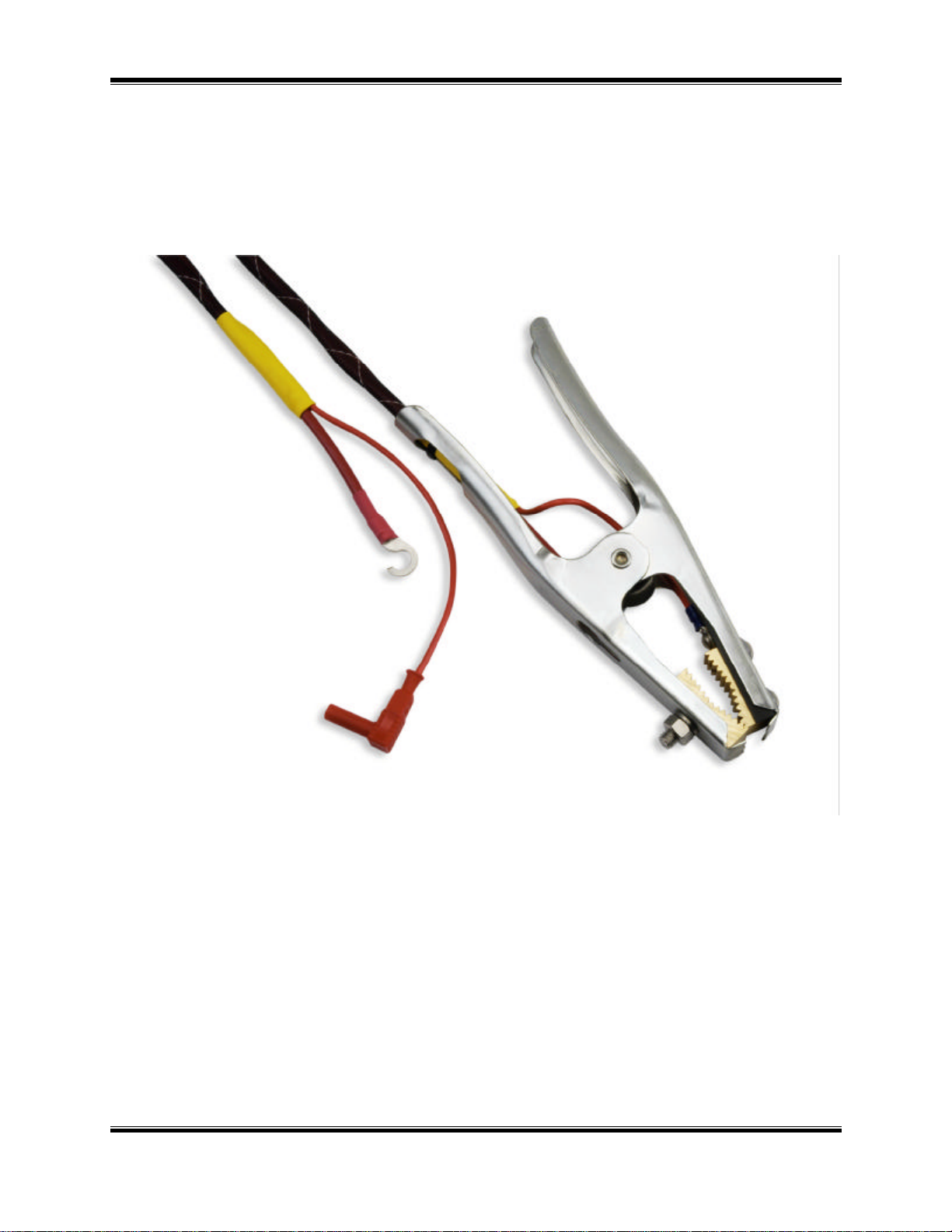
1.4 Furnished Test Accessories
The Herculito is supplied with two 45-foot #8 AWG test cables with heavy-duty alligator
clamps. A Ground cable, power cord and a cable bag are also included with each Herculito.
1.5 Optional Accessories
An optional shipping case (which holds the Herculito and its cables) is also available.
Figure 1 Herculito Current Cable
5
Page 7

Herculito Operating Procedures
2.0 HERCULITO SPECIFICATIONS
Herculito specifications and leading particulars are listed in Table 1.
Table 1 Herculito Specifications
MODEL ......................... Herculito
TYPE................................ Special-Purpose Test Equipment, Portable, Low Resistance-Ohmmeter
SIZE (inches).................. 17” L by 13” W by 7” H (43.2 Cm x 33 Cm x 18.8 Cm)
WEIGHT .......................... Less than 15 pounds (6.8 Kg)
RESISTANCE
RANGE............................ 1 micro-ohm to 300 milli-ohms
TEST CURRENT
RANGE............................ 80 Amperes to 100 Amperes, Auto ranging
DISPLAY......................... Backlit LCD, 2-lines high by 16 characters Wide
ACCURACY.................... ± 1 % Reading, ± 1 Count
MEMORY......................... Retain last 3 readings in memory during test
OPERATING POWER ... 5 amps, 90-230 Vac, 50/60 Hz.
PROTECTION................. thermal-overload sensor and cutoff
COMPUTER INTERFACE.... RS-232C; 19200 Baud (Diagnostic Testing)
ENVIRONMENT ............. Operating: 0°C to 55°C; Storage: -40°C to 65°C
FURNISHED ITEMS....... One power cord, one ground cable, two 45-ft. test lead cables,
and one test-cable carrying bag
WARRANTY.................... One-Year Parts & Labor (Post-Warranty Service Contracts Available)
HERCULITO SPECIFICATIONS ARE SUBJECT TO UPGRADES AND MAY BE CHANGED WITHOUT PRIOR NOTICE.
6
Page 8

Herculito Operating Procedures
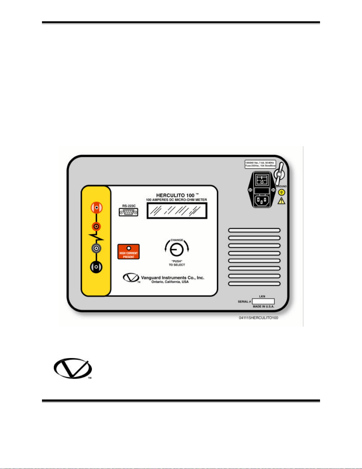
3.0 CONTROL AND DISPLAY
3.1 Herculito Front Panel
The Herculito controls and displays are shown in the control-panel illustration, Figure 2.
Pointing leader lines reference each item with an index number. Each index number is crossreferenced to a functional description in Table 2, which describes the function and purpose of
each item on the control panel. Although the purpose of these controls and the display may seem
obvious and intuitive, users should become familiar with them before attempting to use the
Herculito. First-time users should also review and become familiar with the Safety Summary on
the front page.
Figure 2 Herculito Front Panel
7
Page 9

Herculito Operating Procedures
Table 2 Functional Description of Herculito Controls and Display
Figure 1
Index #
1,8 None Current connector jacks.
Adjacent Panel Marking Functional Description
2
RS-232C
3
no marking
4 GROUND
(Wing Nut)
5 90-230 Vac, 8A, 50- 60 Hz Input power connector with third-wire safety
6
CHANGE
“PUSH”
TO SELECT
RS-232C interface port; 9-pin connector;
female DB type. The data are set to 19,200
baud, 1 start bit, 8 data bits, and no parity bit;
PIN ...............SIGNAL
2 Rx
3 Tx
5 Signal Gnd
This serial port is dedicated for factory
calibration and software update.
LCD; 2-line by 16-character; back-lighted;
displays menus of selections, operator entries,
and test-measurement results.
Herculito ground stud. Connect ground stud
to substation ground using provided cable.
ground, power switch and, fuse holder.
One-knob control (all Herculito menus and
selections are controlled by this one control
knob). Turning this control knob scrolls
through different menu options (shown on
the LCD), which display. Pressing the knob
selects the displayed function, usually
producing a new menu of selectable options.
See Figure 8 for a summary of the step-bystep operating procedures.
7 HIGH CURRENT
PRESENT
9 & 10 (resistor symbol) Voltage-sensing connector jacks.
LED indicator, red; Lights when high-testcurrent is going through the test leads.
8
Page 10

Herculito Operating Procedures
4.0 OPERATING VOLTAGES
The Herculitp operates with voltages between 90-240Vac, 50/60Hz.
5.0 CABLE CONNECTION
The Herculito is supplied with two 45-foot test cables. Both cables are terminated with heavyduty alligator clamps to connect to the device being tested. A typical cable connection for the
Herculito to a device under test is shown in figure 3 and 4. To protect the Herculito against static
discharge in the substation, always connect the unit’s ground stud to the substation ground. It is
also highly recommended to ground one side of the circuit breaker bushing during testing to
eliminate any static discharge through the Herculito.
Figure 3 Herculito Connection Diagram 1
Figure 4 Herculito Connection Diagram 2
9
Page 11

Herculito Operating Procedures
6.0 OPERATING THE HERCULITO
The Herculito is operated with one control knob. The operator turns the control knob to scroll
through different menu selections on the display. When the desired option appears, it is selected
by pressing the control knob like a pushbutton.
6.1 Step-by-Step Procedures
6.1.1 Precautions
CAUTION
Do not measure the resistance of inductive devices. This can generate unsafe highvoltage spikes (created by a collapsing magnetic field) if the test current is interrupted by
detaching a test lead during a test. Do not touch or disconnect any test lead that is
connected to a device under test while current is being conducted. Failure to heed this
warning can result injury to the user and/or damage to the Herculito. The Herculito
measures low, non-inductive resistances (e.g., breaker contacts and bus-bar junctions); If
the resistance of an inductive device is required to be measured, then the use of an
instrument designed for that purpose is recommended (such as the WRM made by the
Vanguard Instruments Company).
6.1.2 Preparations
a. Ground Herculito to Substation ground.
b. Plug the Herculito power cable into a power outlet.
c. Connect current-cable lugs and voltage-sensing cable plugs to control-panel (Figure 2).
d. Attach current test-cable clamps to opposite terminals of the resistive load being tested
(Figure 3 & 4).
e. Turn on Herculito power, by pressing the rocker switch to ON.
NOTE
All Herculito operations begin at the MAIN MENU, which appears after the initial boot-up (after
configuration and software revision data display briefly.) The Main Menu display is shown
below:
MAIN MENU
<RUN TEST>
Figure 5 Main Menu
f. The main menu displays a list of four options, which appear in sequence as the control knob is
turned. The four options of the Main-Menu list are: RUN TEST, ADJ CONTRAST, CAL.
CHECK.
g. When the option of choice appears in the Main Menu, press (or “Push”) the control knob to
enter the selection and start that sequence. The step-by-step operating procedures that follow
describe each of the selected options in the order listed above.
10
Page 12

Herculito Operating Procedures
time
6.1.3 Run Test Procedure
To run a test, turn the control knob until RUN TEST appears on the display, then press the
control knob to begin the procedures for running a test. The following menus prompt the user to
run a test.
MAIN MENU
<RUN TEST>
“PRESS” TO START
“TURN” TO ABORT
WAIT FOR BEEP
THEN RELEASE
Remaining burn-in
BURNING IN: 02
120.1 MICRO-OHM
FINAL TEST RSLT:
120.1 MICRO-OHM
Figure 6 Run Test Menu Prompts
The above menu shows the final resistance measurement and the test current at which the
resistance was measured. After the result is examined, press or turn the control knob for to
return to the “MAIN MENU” menu.
MAIN MENU
<RUN TEST>
Figure 7..Main menu
11
Page 13

Herculito Operating Procedures
From the Main Menu another test can be run. If all test have been completed, turn off power to
the Herculito, disconnect test leads ground cable and power cable, and stow them. This
completes the procedure for performing the Herculitotest procedure.
NOTE
A “Over-Range” message may appear on the Herculito LCD if the current cables or sense cables
are not connected as shown in figure 3 & 4.
FINAL TEST RSLT:
OVER-RANGE
Figure 8 Over-Range Message
6.1.6 Contrast Adjustment
The purpose of this procedure is to adjust the darkness level of the alpha-numeric characters
shown on the LCD display, in order to produce the best readability for the ambient light in the
testing area. To adjust the contrast, turn the control knob to select the ADJ. CONTRAST option
from the Main Menu.
MAIN MENU
<ADJ. CONTRAST>
Figure 9 Select Adjust Contrast Menu
a. Press knob to select “ADJ. CONTRAST” mode. The following menu will be shown.
ADJUST CONTRAST
“PRESS”= DONE
Figure 10 Contrast Menu
b. Turn the control knob for the desired contrast. Press the control knob to set the contrast. The
display will return to the Main Menu. The contrast setting will be recalled each time the
Herculito is turned on and remain until it is changed again using this procedure.
12
Page 14

Herculito Operating Procedures
6.1.7 Herculito Cal Check
The purpose of the Calibration Check is to verify that the Herculito is operating within
acceptable specifications by running a functional check on the Herculito electronics.
To Run a CAL CHECK, turn the control knob to select the CAL CHECK option from the Main
Menu (see Figure11).
MAIN MENU
<CAL CHECK>
Figure 11 Cal Check Menu
a. Press the control knob to begin the calibration check. The following display appears.
ATTACH SHORT BAR
<START CAL CHK>
Figure 12 Attach Short Bar Prompt
b. Attach the test leads to an unused bus bar (several inches apart, the spacing is not critical,
since this is a functional check). See figure 12 for connection illustration. Press the control knob
to start the test.
Figure 13 Calibration Connection
13
Page 15

Herculito Operating Procedures
The following menus will be displayed when the Herculito is going through the Calibration
Check
CAL CHECK
IN PROGRESS >>>
Cal Check in Progress
ZERO CKT CHECK
<PASS>
Zero Circuit Check
FSCALE CKT CHECK
<PASS>
Full Scale Circuit Check
Measure Circuit Check
Press knob to return to main menu.
MEAS CKT CHECK
<PASS>
CAL CHECK DONE!
PRESS KEY …
Figure 13 Cal Check Menus
14
Page 16

Herculito Operating Procedures
6.1.8 Display Previous Results
The purpose of this procedure is to let an operator view the last 3 readings stored in the
Herculito. To view previous results, turn the control knob to select the PREV RESULTS option
from the Main Menu.
MAIN MENU
<PREV RESULTS>
Figure 14 Previous Results Menu
a. Press control knob to select this option. The user now can select any of the last three readings
to be displayed. To select the reading, turn the control knob to one of the menus.
PREVIOUS RESULTS
<LAST TEST>
PREVIOUS RESULTS
<SECOND TO LAST>
PREVIOUS RESULTS
<THIRD TO LAST>
Figure 15 Select Reading Menus
b. When one of the prompts above displays, press the control knob to display its reading.
LAST RESULT:
120.2 MICRO-OHM
Figure 16 Test Record Readout
c. The above display shows the recorded test resistance (120.2 Micro-ohms). When the
displayed record is reviewed and noted, press the control knob to return to the Main Menu. This
ends the PREVIOUS RESULTS procedure.
This concludes the operating procedures for all of the Herculito functions.
15
Page 17

Herculito Operating Procedures
1520 South Hellman Avenue. Ontario, CA 91761, USA
Phone 909-923- 9390 Fax 909-923-9391
Web site: http//www.vanguard-instruments.com
Herculito Nov 2006
16
 Loading...