

Vancare VERA-LIFT II B350, VERA-LIFT II B600 Maintenance Manual
VERA-LIFT II™
MODELS B350 & B600
MAINTENANCE
MANUAL
VANCARE,Inc. Phone: (800) 694-4525
1515 First Street Fax: (402) 694-3994
Aurora, Nebraska 68818 Email: pvancare@hamilton.net
ALL VANCARE PRODUCTS
ARE MADE IN THE U.S.A.

VERA-LIFT II B350 & VERA-LIFT II B600
February 2008 For your nearest Distributor, call 1-800-694-4525 2
MAINTENANCE MANUAL
TABLE OF CONTENTS
VERA-LIFT II DIAGRAM OF PARTS AND DISCRIPTIONS
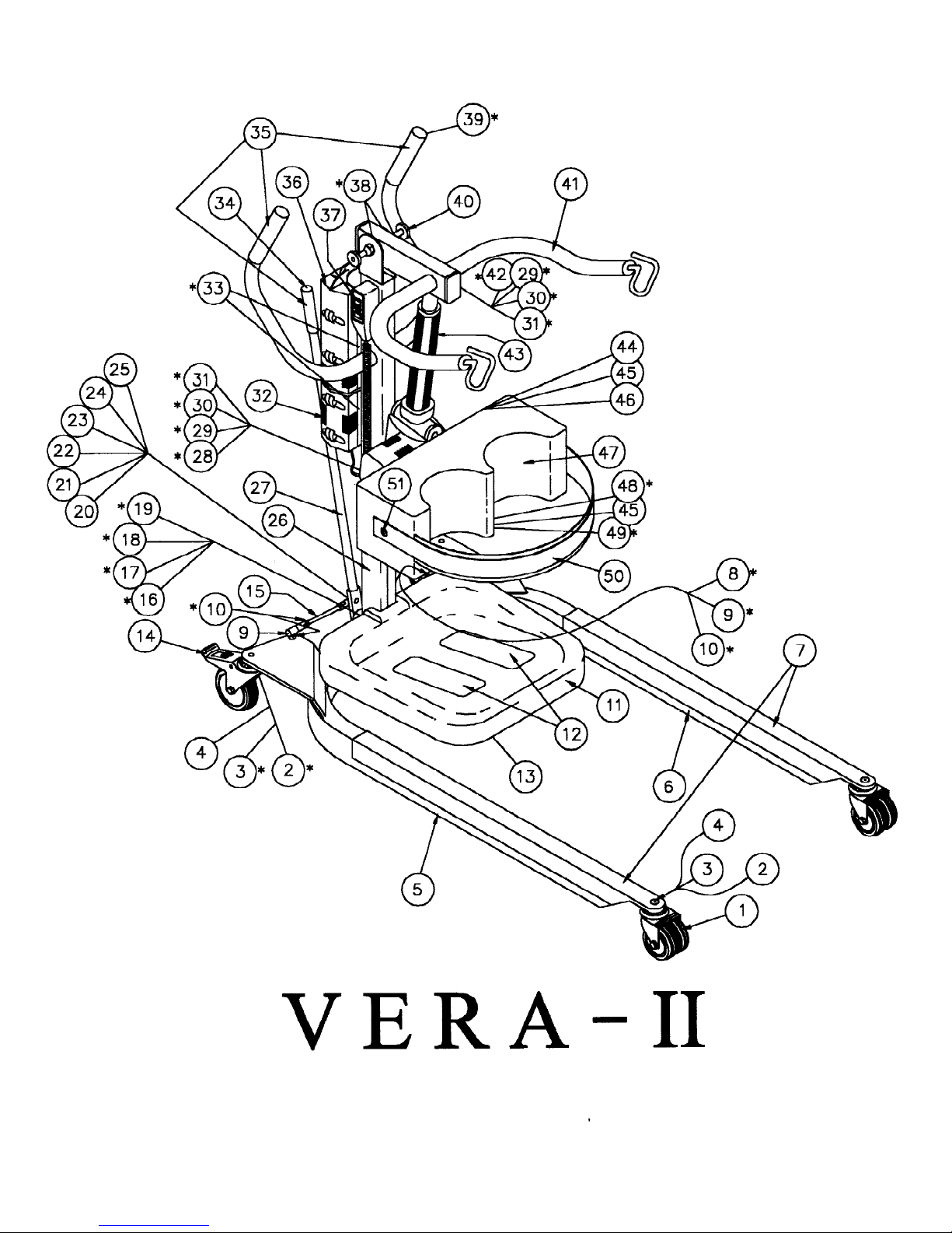
Vera-Lift II diagram, part numbers and descriptions Page 3-4
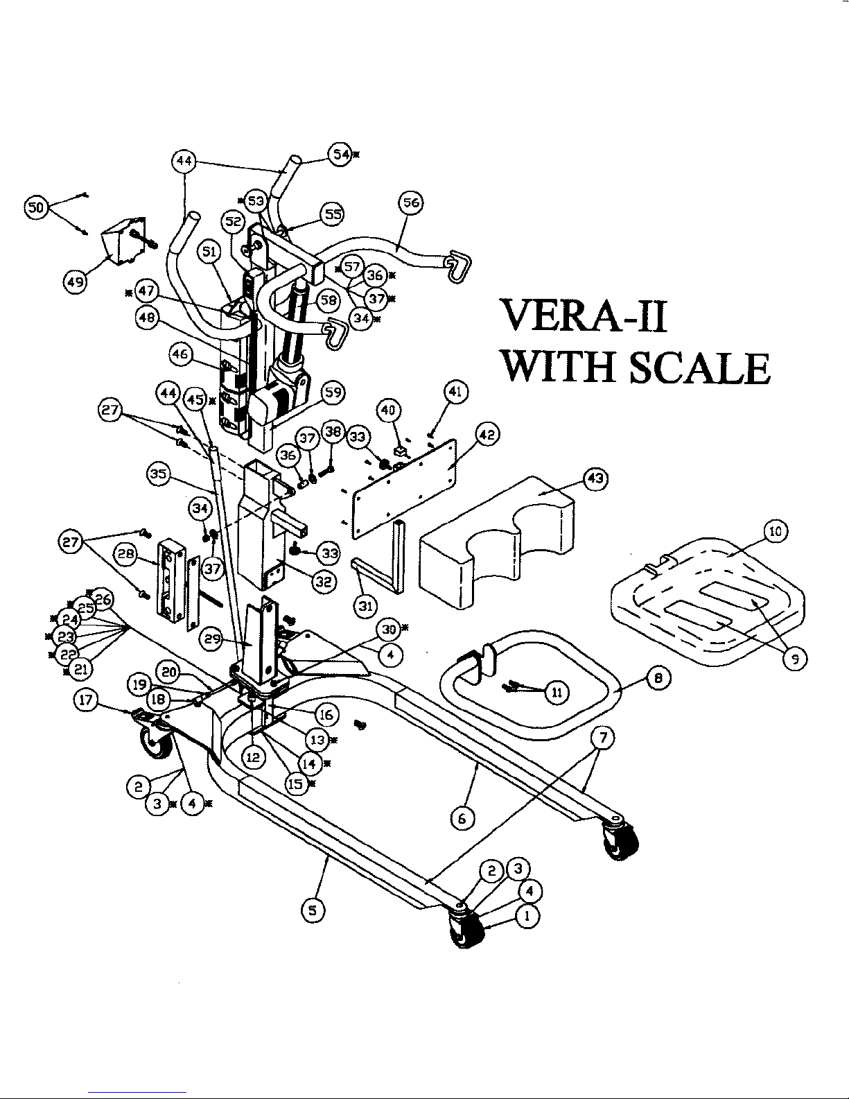
Vera-Lift II w/scale diagram, part numbers and descriptions Page 5-6
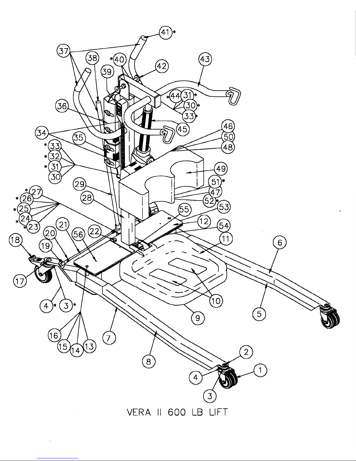
Vera-Lift II 600 diagram, part numbers and descriptions Page 7-8
Vera-Lift II 600 w/scale diagram, part numbers and descriptions Page 9-10
TECHNICAL INSTRUCTIONS FOR MOBILETTE
CONTENTS Page 11
General and Function Page 12
Installation and Startup Page 13-16
Instructions for use Page 17-18
Care and Maintenance Page 18-21
TECHNICAL INSTRUCTIONS FOR VERA-LIFT II ACTUATOR
CONTENTS Page 23
General and Function Page 24-25
Installation and Startup Page 26-27
Operation Page 28-29
Care and Maintenance Page 30
Technical Data and Troubleshooting Page 31-32
TECHNICAL INSTRUCTIONS FOR VERA-LIFT II 600 ACTUATOR
CONTENTS Page 35
Basic Principles
Operating instructions Page 36-37
Organizational measures & Conventions Page 37-38
Safety Program Page 39-42
Structure and Function Page 43-45
Normal and Special Operation Page 46-48
Installation and Initial start up Page 49-51
Maintenance, Malfunctions, and Repairs Page 52-56
Removing from service, Dismantling, and Disposal Page 57-58
Appendix and Index Page 59-61
MONTHLY VERA-LIFT II INSPECTION SHEET Page 62
MONTHLY VERA-LIFT II BELT INSPECTION SHEET Page 64
February 2008 For your nearest Distributor, call 1-800-694-4525 3

VERA II (PURPLE)
y
February 2008 For your nearest Distributor, call 1-800-694-4525 4
REF # PART # DESCRIPTION Qt
1 MFG-9-523190 CASTER 3" NON-LOCK 2
2 MFG-9-238120 3/8-16X1.25 FH-SH/SS 4
3 MFG-9-293810 3/8 EXT LOCK WASHER 4
4 MFG-9-263816 3/8-16 HEX NUT-ZN 4
5 MFG-7-252052 LEG/VERA 2 RIGHT PURPLE 1
6 MFG-7-252051 LEG/VERA 2 LEFT PURPLE 1
7 MFG-5-900105 VERA 2 LEG PROTECTOR - CLEAR 2
8 MFG-6-582601 TIE ROD-2 LEFT/BEND 1
9 MFG-9-583600 TIE ROD END 4
10 MFG-9-263824 3/8-24 N.F. NUT-ZN 8
10* MFG-9-293807 3/8" SPLIT LOCK WASH 4
11 MFG-5-252077 PLASTIC FOOT PLATE 1
12 MFG-5-900070 SAFETY TREAD/GREY 2
13 MFG-7-252075 FOOT STEP FRM/VERA 2 PURPLE 1
14 MFG-9-523120 CASTER 4" LOCKING 2
15 MFG-6-582600 TIE ROD-2 1
16 MFG-9-250047 1/2-13 X 4 SH CS -SS 2
17 MFG-9-295062 WASHER .062/SS 2
18 MFG-9-295040 WASHER .040/SS 2
19 MFG-9-265010 1/2-13 HEX NUT -ZN 2
20 MFG-6-542470 INDEX ARM-2 1
21 MFG-6-542575 INDEX GUIDE BOLT 1
22 MFG-6-542212 .060 RACE 2
23 MFG-6-542211 .078 THRUST BEARING 1
24 MFG-5-704000 1" GREEN SPRING/DANLY 1
25 MFG-9-250030 7/16-20 INDEX ARM SHLDR BOLT 1
26 MFG-7-252060 MAST/VERA 2 PURPLE 1
27 MFG-6-573290 SHIFT BAR-2 (29") 1
28 MFG-9-238154 3/8-16X1.5 HH GR5 Z 1
29 MFG-9-677100 ACTUATOR SPACER 2
30 MFG-9-295012 WASHER .020/NYLON 4
31 MFG-9-263820 3/8-16 NYLON LOCKNUT 2
32 MFG-9-322200 MOBILETTE CONTROL 1
33 MFG-9-225850 1/4-28-1/2 BH SH-SS 2
34 MFG-9-633820 7/8" END CAP-RUBBER 1
36 MFG-9-321450 BATTERY-(II) 1
37 MFG-6-370200 PEND-2 W/CORD COMP. 1
38 MFG-9-624110 BRONZE BUSHING 3/4" 2
39 MFG-9-671050 1-1/4" ROUND RIBBED PLUG 2
40 MFG-5-925200 EXT AXIS PIN-COMP/2 1
41 MFG-7-252020 ARM/VERA 2 PURPLE 1
42 MFG-9-268152 3/8-16X1.5 BH SH(SS) 1
43 MFG-5-602050 VERA II ACT. 7.87" 1
44 MFG-7-252071 VERA-II KNEE PLATE (PURPLE) 1
45 MFG-5-925525 KNEE BRKT KNOB 1-1/4 2
46 MFG-9-270658 #6 X 5/8 FH PH ZINC 6
47 SEW-5-500122 VERA-2 KNEE PAD 1
48 MFG-7-252070 KNEE PAD BKT/VERA 2 PURPLE 1
49 MFG-9-671775 PLASTIC PLUG-3/4 SQ 1
50 SEW-5-900012 V-2 KNEE PAD STRAP 1
51 MFG-5-925500 KNEE BRKT KNOB 5/8" 2
* MFG-9-212500 RIVOT, LEG PROTECTOR 4
* MFG-9-321224 MAINS ADAPTER 1
* NOT PICTURED
VERA-II
WITH SCALE
February 2008 For your nearest Distributor, call 1-800-694-4525 5

VERA II W/SCALE (PURPLE)
#
Y
February 2008 For your nearest Distributor, call 1-800-694-4525 6
REF # PART
1 MFG-9-523190 CASTER 3" NON-LOCK 2
2 MFG-9-238120 3/8-16X1.25 FH-SH/SS 4
3 MFG-9-293810 3/8 EXT LOCK WASHER 4
4 MFG-9-263816 3/8-16 HEX NUT-ZN 7
5 MFG-7-252052 LEG/VERA 2 RIGHT PURPLE 1
6 MFG-7-252051 LEG/VERA 2 LEFT PURPLE 1
7 MFG-5-900105 VERA 2 LEG PROTECTOR - CLEAR 2
8 MFG-7-252177 V-2/SCALE FOOTSTP FRAME PURPLE 1
9 MFG-5-900070 SAFETY TREAD/GREY 2
10 MFG-5-252077 PLASTIC FOOT PLATE 1
11 MFG-9-231750 5/16-18-3/4 HH (SS) 2
12 MFG-9-250047 1/2-13 X 4 SH CS -SS 2
13 MFG-9-295062 WASHER .062/SS 2
14 MFG-9-295040 WASHER .040/SS 2
15 MFG-9-265015 ACORN NUT 1/2-13 2
16 MFG-7-542670 BASE II/SCALE PURPLE 1
17 MFG-9-523120 CASTER 4" LOCKING 2
18 MFG-9-583600 TIE ROD END 4
19 MFG-9-263824 3/8-24 N.F. NUT-ZN 8
20* MFG-6-582601 TIE ROD-2 LEFT/BEND 1
20 MFG-6-582600 TIE ROD-2 1
21 MFG-6-542770 INDEX ARM-2/SCALE 1
22 MFG-6-542575 INDEX GUIDE BOLT 1
23 MFG-5-704000 1" GREEN SPRING/DANLY 1
24 MFG-6-542212 .060 RACE 2
25 MFG-6-542211 .078 THRUST BEARING 1
26 MFG-9-250030 7/16-20 INDEX ARM SHLDR BOLT 1
27 MFG-9-238107 3/8-16 X 1 FH SH(SS) 4
28 MFG-6-771017 MAST/SCALE LOAD CELL 1
29 MFG-7-542870 V-2, V-L 2 CELL MOUNT (PURPLE) 1
30* MFG-9-293807 3/8" SPLIT LOCK WASH 7
30 MFG-9-238122 3/8-16 X 1 1/4 HH-G5 3
31 MFG-7-252070 KNEE PAD BKT/VERA 2 PURPLE 1
32 MFG-7-252047 V-2/SCALE CELL HOUSING PURPLE 1
33 MFG-5-925525 KNEE BRKT KNOB 1-1/4 2
34 MFG-9-263820 3/8-16 NYLON LOCKNUT 2
35 MFG-6-573290 SHIFT BAR-2 (29") 1
36 MFG-9-677100 ACTUATOR SPACER 2
37 MFG-9-295012 WASHER .020/NYLON 4
38 MFG-9-238154 3/8-16X1.5 HH GR5 Z 1
40 MFG-9-671775 PLASTIC PLUG-3/4 SQ 1
41 MFG-9-270658 #6 X 5/8 FH PH ZINC 8
42 MFG-7-252071 VERA-II KNEE PLATE (PURPLE) 1
43 SEW-5-500122 VERA-2 KNEE PAD 1
45 MFG-9-633820 7/8" END CAP-RUBBER 1
46 MFG-9-322200 MOBILETTE CONTROL 1
47 MFG-9-271040 10-24 X 3/8" HH 1
48 MFG-9-271150 10-24 X 1.5" HH 1
49 MFG-6-771007 MAST/SCALE METER(SS) 1
50 MFG-9-225880 1/4-28-1 1/4 BH SH-SS 2
51 MFG-9-321450 BATTERY-(II) 1
52 MFG-6-370200 PEND-2 W/CORD COMP. 1
53 MFG-9-624110 BRONZE BUSHING 3/4" 2
54 MFG-9-671050 1-1/4" ROUND RIBBED PLUG 2
55 MFG-5-925200 EXT AXIS PIN-COMP/2 1
56 MFG-7-252020 ARM/VERA 2 PURPLE 1
57 MFG-9-268152 3/8-16X1.5 BH SH(SS) 1
58 MFG-5-602050 VERA II ACT. 7.87" 1
59 MFG-7-252067 MAST-VERA 2 /SCALE PURPLE 1
60* MFG-5-925500 KNEE BRKT KNOB 5/8" 2
60* SEW-5-900012 V-2 KNEE PAD STRAP 1
61* MFG-9-321205 V-2/S CONTROL SHIM 1
62* MFG-9-321218 CABLE EXTENSION 1
63* MFG-9-321224 MAINS ADAPTER 1
* MFG-9-212500 RIVOT, LEG PROTECTOR 4
DESCRIPTION QT
* NOT PICTURED
February 2008 For your nearest Distributor, call 1-800-694-4525 7

VERA II 600 (PURPLE)
February 2008 For your nearest Distributor, call 1-800-694-4525 8
Ref # Component ID Component Description Qty
1 MFG-9-523190 CASTER 3" NON-LOCK 2
2 MFG-9-238120 3/8-16X1.25 FH-SH/SS 2
3 MFG-9-293810 3/8 EXT LOCK WASHER 4
4 MFG-9-263816 3/8-16 HEX NUT-ZN 4
5 MFG-7-600001 SERIES II 600 LEG LEFT PURPLE 1
6 MFG-4-900616 600 LEG PROTECTOR - CLEAR LEFT 1
7 MFG-7-600002 SERIES II 600 LEG RIGHT PURPLE 1
8 MFG-4-900617 600 LEG PROTECTOR CLEAR RIGHT 1
9 MFG-7-252074 VERA II 600 FOOTSTEP (PURPLE) 1
10 MFG-5-900070 SAFETY TREAD/GREY 3
11 MFG-5-252078 WIDE PLASTIC FOOTPLATE 600 1
12 MFG-6-000522 PLASTIC LIDS 2
13 MFG-9-295040 WASHER .040/SS 2
14 MFG-9-295062 WASHER .062/SS 2
15 MFG-9-265013 1/2-13 CAP NUT L/D 2
16 MFG-9-250050 1/2-13 X 5 HH G5-LEG 2
17 MFG-9-238153 3/8-16X 1.5 FH SH/SS 2
18 MFG-9-523120 CASTER 4" LOCKING 2
19 MFG-6-583650 CUT TIE ROD ENDS 2
20 MFG-9-263824 3/8-24 N.F. NUT-ZN 6
21 MFG-4-900605 600 TIE ROD-CHROMED 2
22 MFG-9-238100 3/8-16 X 1 GR 5 B0LT 2
23 MFG-6-542575 INDEX GUIDE BOLT 1
24 MFG-6-542470 INDEX ARM-2 1
25 MFG-6-542212 .060 RACE 2
26 MFG-6-542211 .078 THRUST BEARING 1
27 MFG-5-704000 1" GREEN SPRING/DANLY 1
28 MFG-7-252066 MAST-VERA 2 600 (PURPLE) 1
29 MFG-6-573290 SHIFT BAR-2 (29") 1
30 MFG-9-263820 3/8-16 NYLON LOCKNUT 2
31 MFG-9-677100 ACTUATOR SPACER 2
32 MFG-9-295012 WASHER .020/NYLON 4
33 MFG-9-238154 3/8-16X1.5 HH GR5 Z 1
34 MFG-9-225850 1/4-28-1/2 BH SH-SS 2
35 MFG-9-322205 MOBILETTE CONTROL VERA II 600 1
36 MFG-9-321450 BATTERY-(II) 1
38 MFG-9-633820 7/8" END CAP-RUBBER 1
39 MFG-6-370200 PEND-2 W/CORD COMP. 1
40 MFG-9-624110 BRONZE BUSHING 3/4" 2
41 MFG-9-671050 1-1/4" ROUND RIBBED PLUG 2
42 MFG-5-925200 EXT AXIS PIN-COMP/2 1
43 MFG-7-252016 ARM-VERA 2 600 (PURPLE) 1
44 MFG-9-268152 3/8-16X1.5 BH SH(SS) 1
45 MFG-5-602055 VERA II 600 ACTUATOR 1
46 MFG-7-252068 VII 600TALL KNEE PD PLT PURPLE 1
47 MFG-5-925525 KNEE BRKT KNOB 1-1/4 2
48 MFG-9-270658 #6 X 5/8 FH PH ZINC 6
49 SEW-5-500600 VERA II 600 CONTOUR KNEE PAD 1
50 MFG-5-925500 KNEE BRKT KNOB 5/8" 2
51 MFG-7-252070 KNEE PAD BKT/VERA 2 PURPLE 1
52 MFG-9-671775 PLASTIC PLUG-3/4 SQ 1
53 MFG-7-600004 SERIES II 600 BASE BOX PURPLE 1
54 MFG-9-583600 TIE ROD END 2
55 MFG-9-244020 7/16 X 2 HH GR 5 1
56 MFG-9-225750 1/4-20 X 3/4 FH PH 4
* MFG-5-738630 1 1/2" SPACER-ACETAL 1
* MFG-9-212500 RIVOT, LEG PROTECTOR 4
* MFG-9-250047 1/2-13 X 4 SH CS -SS 1
* MFG-9-264420 7/16 NYLON LOCK NUT 1
* MFG-9-265010 1/2-13 HEX NUT -ZN 2
* MFG-9-270660 #6 X 1 FH PH SCREW ZINC 10
* MFG-9-293807 3/8" SPLIT LOCK WASH 4
* MFG-9-294400 7/16 WRGHT FLAT WASH 1
* MFG-9-321218 CABLE EXTENSION 1
* MFG-9-321224 MAINS ADAPTER 1
* MFG-9-620500 1/2" LOCKING HOLE PLUG 1
* MFG-9-620875 7/8" LOCKING HOLE PLUG 1
* SEW-5-900106 VERA II 600 KNEE PAD STRAP 1
* NOT PICTURED
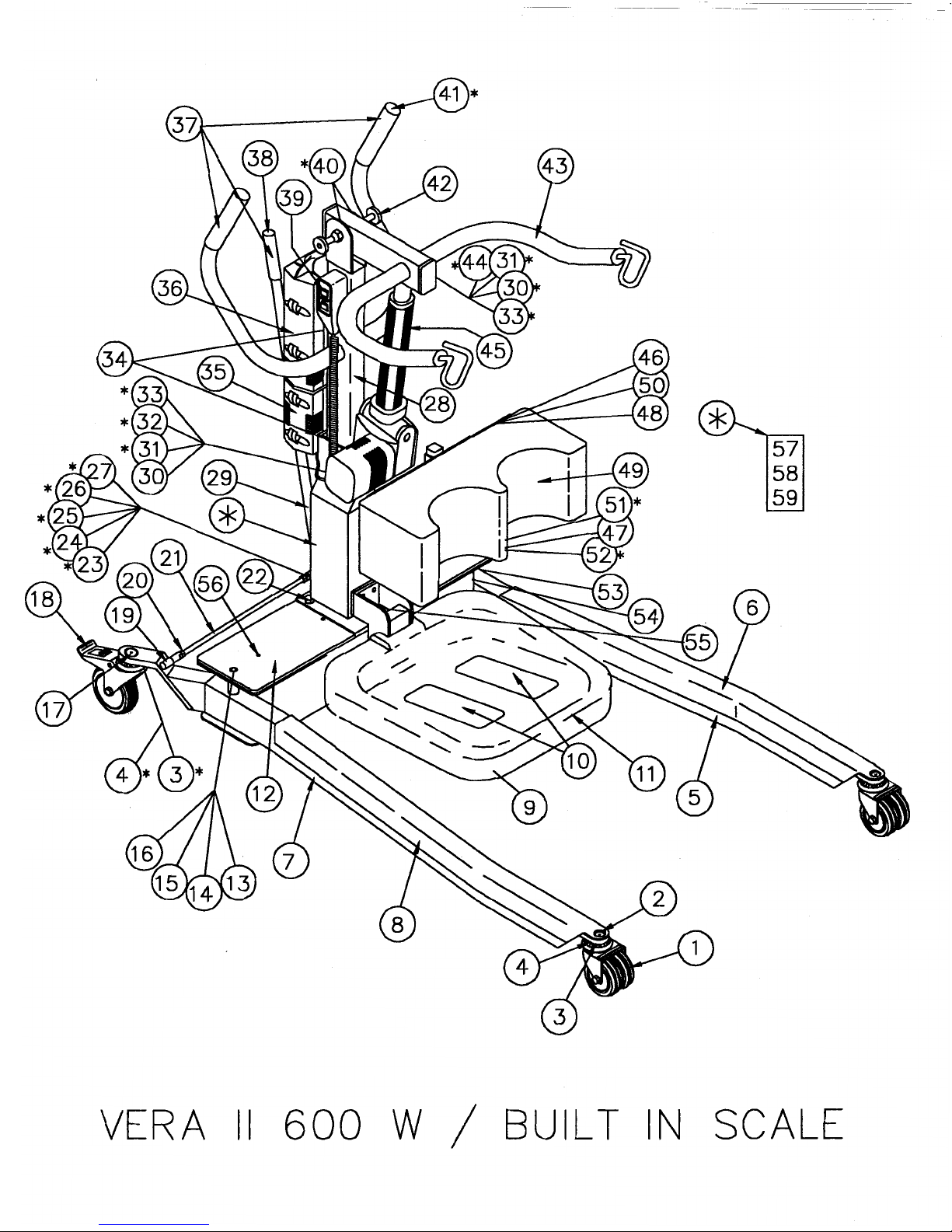
February 2008 For your nearest Distributor, call 1-800-694-4525 9

VERA II 600 W/SCALE (PURPLE)
February 2008 For your nearest Distributor, call 1-800-694-4525 10
REF # PART # DECSCRIPTION QTY
1 MFG-9-523190 CASTER 3" NON-LOCK 2
2 MFG-9-238120 3/8-16X1.25 FH-SH/SS 2
3 MFG-9-293810 3/8 EXT LOCK WASHER 4
4 MFG-9-263816 3/8-16 HEX NUT-ZN 5
5 MFG-7-600001 SERIES II 600 LEG LEFT PURPLE 1
6 MFG-4-900616 600 LEG PROTECTOR - CLEAR LEFT 1
7 MFG-7-600002 SERIES II 600 LEG RIGHT PURPLE 1
8 MFG-4-900617 600 LEG PROTECTOR CLEAR RIGHT 1
9 MFG-7-252079 V II 600 W/SCALE FOOTSTEP PURP 1
10 MFG-5-900070 SAFETY TREAD/GREY 2
11 MFG-5-252077 PLASTIC FOOT PLATE 1
12 MFG-6-000522 PLASTIC LIDS 2
13 MFG-9-250050 1/2-13 X 5 HH G5-LEG 2
14 MFG-9-295040 WASHER .040/SS 2
15 MFG-9-295062 WASHER .062/SS 2
16 MFG-9-265013 1/2-13 CAP NUT L/D 2
17 MFG-9-238153 3/8-16X 1.5 FH SH/SS 2
18 MFG-9-523120 CASTER 4" LOCKING 2
19 MFG-9-583600 TIE ROD END 2
21 MFG-4-900605 600 TIE ROD-CHROMED 2
22 MFG-9-238175 3/8-16x1.75 HH GR5 Z 3
23 MFG-6-542470 INDEX ARM-2 1
24 MFG-6-542211 .078 THRUST BEARING 1
25 MFG-6-542212 .060 RACE 2
26 MFG-5-704000 1" GREEN SPRING/DANLY 1
27 MFG-9-250047 1/2-13 X 4 SH CS -SS 1
27 MFG-9-265010 1/2-13 HEX NUT -ZN 2
28 MFG-7-252058 MAST VII 600 W/SCALE PURPLE 1
29 MFG-6-573290 SHIFT BAR-2 (29") 1
30 MFG-9-263820 3/8-16 NYLON LOCKNUT 2
31 MFG-9-677100 ACTUATOR SPACER 2
32 MFG-9-238154 3/8-16X1.5 HH GR5 Z 1
33 MFG-9-295012 WASHER .020/NYLON 4
34 MFG-9-225880 1/4-28 X 1 1/4" HH 2
35 MFG-9-322205 MOBILETTE CONTROL VERA II 600 1
36 MFG-9-321450 BATTERY-(II) 1
38 MFG-9-633820 7/8" END CAP-RUBBER 1
39 MFG-6-370200 PEND-2 W/CORD COMP. 1
40 MFG-9-624110 BRONZE BUSHING 3/4" 2
41 MFG-9-671050 1-1/4" ROUND RIBBED PLUG 2
42 MFG-5-925200 EXT AXIS PIN-COMP/2 1
43 MFG-7-252016 ARM-VERA 2 600 (PURPLE) 1
44 MFG-9-268152 3/8-16X1.5 BH SH(SS) 1
45 MFG-5-602055 VERA II 600 ACTUATOR 1
46 MFG-7-252068 VII 600TALL KNEE PD PLT PURPLE 1
47 MFG-7-252070 KNEE PAD BKT/VERA 2 PURPLE 1
48 MFG-5-925500 KNEE BRKT KNOB 5/8" 2
49 SEW-5-500600 VERA II 600 CONTOUR KNEE PAD 1
50 MFG-9-270658 #6 X 5/8 FH PH ZINC 6
51 MFG-5-925525 KNEE BRKT KNOB 1-1/4 2
52 MFG-9-671775 PLASTIC PLUG-3/4 SQ 1
54 MFG-7-600004 SERIES II 600 BASE BOX PURPLE 1
55 MFG-9-231750 5/16-18-3/4 HH (SS) 2
56 MFG-9-225750 1/4-20 X 3/4 FH PH 4
57 MFG-6-771017 MAST/SCALE LOAD CELL 1
58 MFG-7-542870 V-2, V-L 2 CELL MOUNT (PURPLE) 1
59 MFG-7-252048 V II 600 SCALE CELL HOUSING P 1
* MFG-5-738630 1 1/2" SPACER-ACETAL 1
* MFG-6-542575 INDEX GUIDE BOLT 1
* MFG-6-583650 CUT TIE ROD ENDS 2
* MFG-6-771007 MAST/SCALE METER(SS) 1
* MFG-7-300040 ALUMINUM SCALE WEDGE PURPLE 1
* MFG-9-212500 RIVOT, LEG PROTECTOR 4
* MFG-9-271052 #10-24-1/2 BH SH-SS 2
* MFG-9-293510 5/16" SPLIT LOCK WSHR 2
* MFG-9-293807 3/8" SPLIT LOCK WASH 5
* MFG-9-321205 V-2/S CONTROL SHIM 1
* MFG-9-321218 CABLE EXTENSION 1
* MFG-9-321224 MAINS ADAPTER 1
* SEW-5-900106 VERA II 600 KNEE PAD STRAP 1
* MFG-9-263824 3/8-24 N.F. NUT-ZN 6
* NOT PICTURED
531e2931_0101
MOBILETTE MCU
Mobile control unit
for DC linear actuators
Contents
1 General . . . . . . . . . . . . . . . . . . . . . . . . . . . . . . . . . . . . . . . . . . . . . . . . . . . . . . . . . . . . . . . . . . . . . . . . . . . . . . . . . . . . . . . . . . . . . . . . . . . . . . . . .2
1.1 Using the Technical Instructions . . . . . . . . . . . . . . . . . . . . . . . . . . . . . . . . . . . . . . . . . . . . . . . . . . . . . . . . . . . . . . . . . . . . . . . . . . . . . . . . . .2
1.2 Explanation of symbols . . . . . . . . . . . . . . . . . . . . . . . . . . . . . . . . . . . . . . . . . . . . . . . . . . . . . . . . . . . . . . . . . . . . . . . . . . . . . . . . . . . . . . . . .2
2 Function . . . . . . . . . . . . . . . . . . . . . . . . . . . . . . . . . . . . . . . . . . . . . . . . . . . . . . . . . . . . . . . . . . . . . . . . . . . . . . . . . . . . . . . . . . . . . . . . . . . . . . . .2
2.1 Correct usage . . . . . . . . . . . . . . . . . . . . . . . . . . . . . . . . . . . . . . . . . . . . . . . . . . . . . . . . . . . . . . . . . . . . . . . . . . . . . . . . . . . . . . . . . . . . . . . . .2
2.2 Ambient conditions . . . . . . . . . . . . . . . . . . . . . . . . . . . . . . . . . . . . . . . . . . . . . . . . . . . . . . . . . . . . . . . . . . . . . . . . . . . . . . . . . . . . . . . . . . . .3
3 Installation and startup . . . . . . . . . . . . . . . . . . . . . . . . . . . . . . . . . . . . . . . . . . . . . . . . . . . . . . . . . . . . . . . . . . . . . . . . . . . . . . . . . . . . . . . . . . . .3
3.1 Scope of delivery . . . . . . . . . . . . . . . . . . . . . . . . . . . . . . . . . . . . . . . . . . . . . . . . . . . . . . . . . . . . . . . . . . . . . . . . . . . . . . . . . . . . . . . . . . . . . .3
3.2 Installing the control unit . . . . . . . . . . . . . . . . . . . . . . . . . . . . . . . . . . . . . . . . . . . . . . . . . . . . . . . . . . . . . . . . . . . . . . . . . . . . . . . . . . . . . . .4
3.3 Inserting the battery pack . . . . . . . . . . . . . . . . . . . . . . . . . . . . . . . . . . . . . . . . . . . . . . . . . . . . . . . . . . . . . . . . . . . . . . . . . . . . . . . . . . . . . . .4
3.4 Connecting the actuator and the control device . . . . . . . . . . . . . . . . . . . . . . . . . . . . . . . . . . . . . . . . . . . . . . . . . . . . . . . . . . . . . . . . . . . . . .5
3.5 Startup . . . . . . . . . . . . . . . . . . . . . . . . . . . . . . . . . . . . . . . . . . . . . . . . . . . . . . . . . . . . . . . . . . . . . . . . . . . . . . . . . . . . . . . . . . . . . . . . . . . . . .6
4 Instructions for use . . . . . . . . . . . . . . . . . . . . . . . . . . . . . . . . . . . . . . . . . . . . . . . . . . . . . . . . . . . . . . . . . . . . . . . . . . . . . . . . . . . . . . . . . . . . . . . .7
4.1 Controlling an actuator . . . . . . . . . . . . . . . . . . . . . . . . . . . . . . . . . . . . . . . . . . . . . . . . . . . . . . . . . . . . . . . . . . . . . . . . . . . . . . . . . . . . . . . . .7
4.2 EMERGENCY STOP function . . . . . . . . . . . . . . . . . . . . . . . . . . . . . . . . . . . . . . . . . . . . . . . . . . . . . . . . . . . . . . . . . . . . . . . . . . . . . . . . . . . . . .7
4.3 "Emergency Lowering" (option) . . . . . . . . . . . . . . . . . . . . . . . . . . . . . . . . . . . . . . . . . . . . . . . . . . . . . . . . . . . . . . . . . . . . . . . . . . . . . . . . . . .8
5 Care and maintenance . . . . . . . . . . . . . . . . . . . . . . . . . . . . . . . . . . . . . . . . . . . . . . . . . . . . . . . . . . . . . . . . . . . . . . . . . . . . . . . . . . . . . . . . . . . . .8
5.1 Maintenance . . . . . . . . . . . . . . . . . . . . . . . . . . . . . . . . . . . . . . . . . . . . . . . . . . . . . . . . . . . . . . . . . . . . . . . . . . . . . . . . . . . . . . . . . . . . . . . . . .8
5.2 Functional checks . . . . . . . . . . . . . . . . . . . . . . . . . . . . . . . . . . . . . . . . . . . . . . . . . . . . . . . . . . . . . . . . . . . . . . . . . . . . . . . . . . . . . . . . . . . . .8
5.3 Care . . . . . . . . . . . . . . . . . . . . . . . . . . . . . . . . . . . . . . . . . . . . . . . . . . . . . . . . . . . . . . . . . . . . . . . . . . . . . . . . . . . . . . . . . . . . . . . . . . . . . . . .9
5.4 Warranty . . . . . . . . . . . . . . . . . . . . . . . . . . . . . . . . . . . . . . . . . . . . . . . . . . . . . . . . . . . . . . . . . . . . . . . . . . . . . . . . . . . . . . . . . . . . . . . . . . . .9
5.5 Disposal . . . . . . . . . . . . . . . . . . . . . . . . . . . . . . . . . . . . . . . . . . . . . . . . . . . . . . . . . . . . . . . . . . . . . . . . . . . . . . . . . . . . . . . . . . . . . . . . . . . . .9
5.6 Technical data . . . . . . . . . . . . . . . . . . . . . . . . . . . . . . . . . . . . . . . . . . . . . . . . . . . . . . . . . . . . . . . . . . . . . . . . . . . . . . . . . . . . . . . . . . . . . . .10
5.7 Liability . . . . . . . . . . . . . . . . . . . . . . . . . . . . . . . . . . . . . . . . . . . . . . . . . . . . . . . . . . . . . . . . . . . . . . . . . . . . . . . . . . . . . . . . . . . . . . . . . . . . .10
5.8 Troubleshooting and fault elimination . . . . . . . . . . . . . . . . . . . . . . . . . . . . . . . . . . . . . . . . . . . . . . . . . . . . . . . . . . . . . . . . . . . . . . . . . . . . .11
Applied standards:
EN 60601-1
EN 60601-1-2
EN ISO 10535
UL 2601
Magnetic Elektromoten AG
Oristalstrasse 97
CH-4410 Liestal
Technical Instructions
February 2008 For your nearest Distributor, call 1-800-694-4525 11
Technical instructions Control unit Mobilette
531e2931_0101 Magnetic – The Linear Drives Company™ page 2/11
1 General
1.1 Using the Technical Instructions
The Technical Instructions are intended for designers who use the Mobilette in their
products, and for engineers who work with the Mobilette. The Technical Instructions
contain all relevant information on this Magnetic product. We reserve the right to
make changes which are in the interest of technical progress.
Please read the Technical Instructions carefully and, above all, pay careful attention to
the Safety Instructions.
The Technical Instructions can be used for drawing up the User Manual for the end
product.
1.2 Explanation of symbols
The symbols opposite are used in the Technical Instructions to highlight possible dangers and important notes.
2 Function
The MOBILETTE control unit (MCU) is used for the mains-independent control of 24V
DC actuators. A distinction is made between two versions:
The MCU1 is connected to the mains voltage using a mains adapter. Protection class
IPx4 applies to the MCU1.
The MCU8 (MCU4) is connected directly to the 230V (120V) mains supply, which is
transformed to 24 V DC via an integrated transformer. This component is subject to
protection class IPx3.
This battery pack consists of 2 batteries connected in series, each of 12 V 4.5 Ah,
resulting in a total of 24 V. The charged battery pack can be used to power the control
unit and thus the actuator. Operation is via a connected control device, e.g. a
handswitch.
An integrated current cut-off protects the actuator from overloading.
An integrated „EMERGENCY STOP“ function can be used to cut off the power supply
to the actuator, so that it immediately stops moving.
2.1 Correct usage
The Mobilette has been designed for mobile applications in the medical field, particularly for patient lifts. The Mobilette is used to control the following Magnetic actuators
§ Matrix MAX10 / MAX30
§ Telemag THG / TLG
Other applications must be approved by Magnetic AG, Liestal.
2.2 Ambient conditions
Operation:
Temperature 10°C to 40°C
Humidity max. 85%
Storage / transport:
Temperature -20°C to 60°C
Humidity max. 95%
This symbol designates pertinent and useful
notes for the user.
This symbol is used to indicate operations
and states which could endanger persons or
property.
Follow the instructions precisely!
Usage in environments where X-ray irradiation is present is strictly forbidden.
The Mobilette must not be used in explosive
atmospheres.
February 2008 For your nearest Distributor, call 1-800-694-4525 12
Technical instructions Control unit Mobilette
531e2931_0101 Magnetic – The Linear Drives Company™ page 3/11
3 Installation and startup
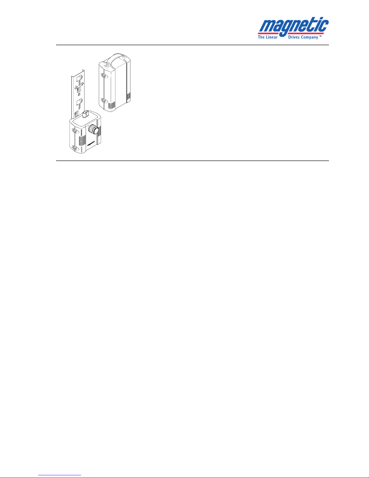
3.1 Scope of delivery
The Mobilette consists of:
ZBA battery unit
MCU control unit (installed on system carrier ?)
Plug-in connections are marked on the control unit for:
Mains adapter with closure flap (MCU1 only)
Mains cable (MCU4 / MCU8 only)
Control device
1 actuator (2nd actuator optional)
Accessories
ZKA mains cable (MCU4 / MCU8 only)
ZDV mains adapter (MCU1 only)
Wall charging station
EHA handswitch
EFE footswitch
IHA infrared handswitch
SPP locking device
Distribution box
Options
Connection for second actuator
Electrical emergency lowering (for channel 1 only)
Individual power cut-off for both channels
MCU4 / MCU8
MCU1
1
3
2
6
7
4
5
Fig. 1 – Scope of delivery and connections
The Mobilette is only suitable for indoor
use.
Do not expose the Mobilette to the effects
of weather.
February 2008 For your nearest Distributor, call 1-800-694-4525 13
Technical instructions Control unit Mobilette
531e2931_0101 Magnetic – The Linear Drives Company™ page 4/11
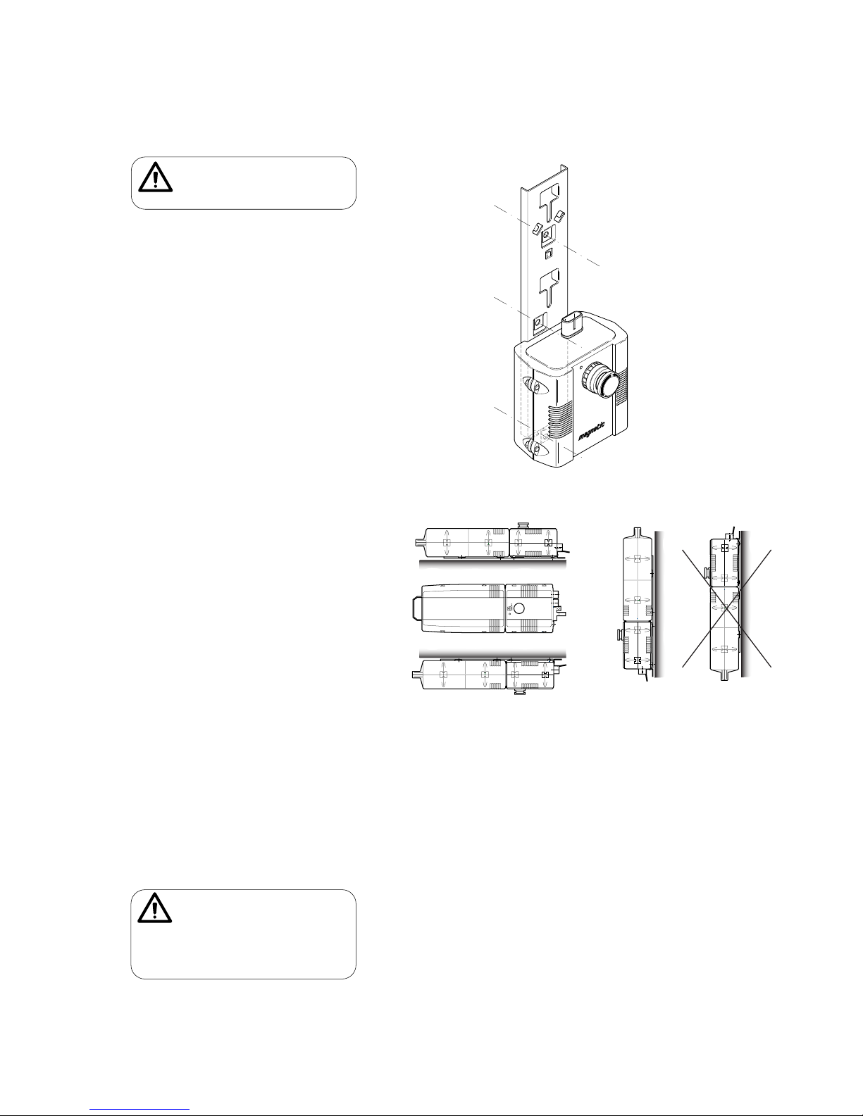
3.2 Installing the control unit
Mount the control unit in the 3 holes provided on the system carrier (Fig. 2).
The MOBILETTE MCU1 can be mounted in the following positions (Fig. 3):
Lying horizontally
Standing horizontally
Hanging horizontally
Vertically (battery pack above the control unit)
The MOBILETTE MCU4 and MCU8 (protection class IPx3) may only be mounted vertically with the battery pack above the control unit (Fig. 3, Pos.
f). This prevents the
possibility of fluid entering the system.
A vertical, hanging position (
g) with the battery pack below the control unit is not
possible, since the battery pack may fall out.
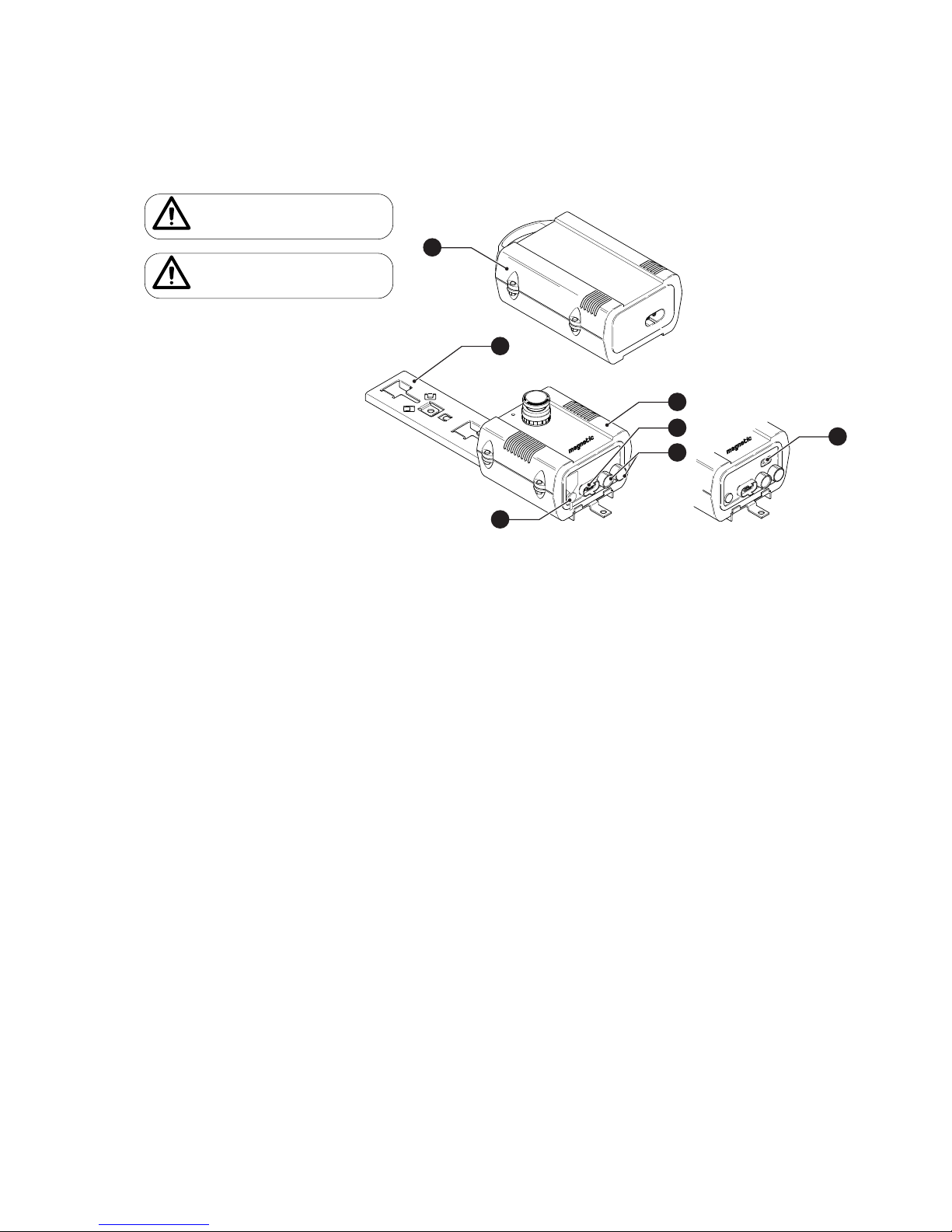
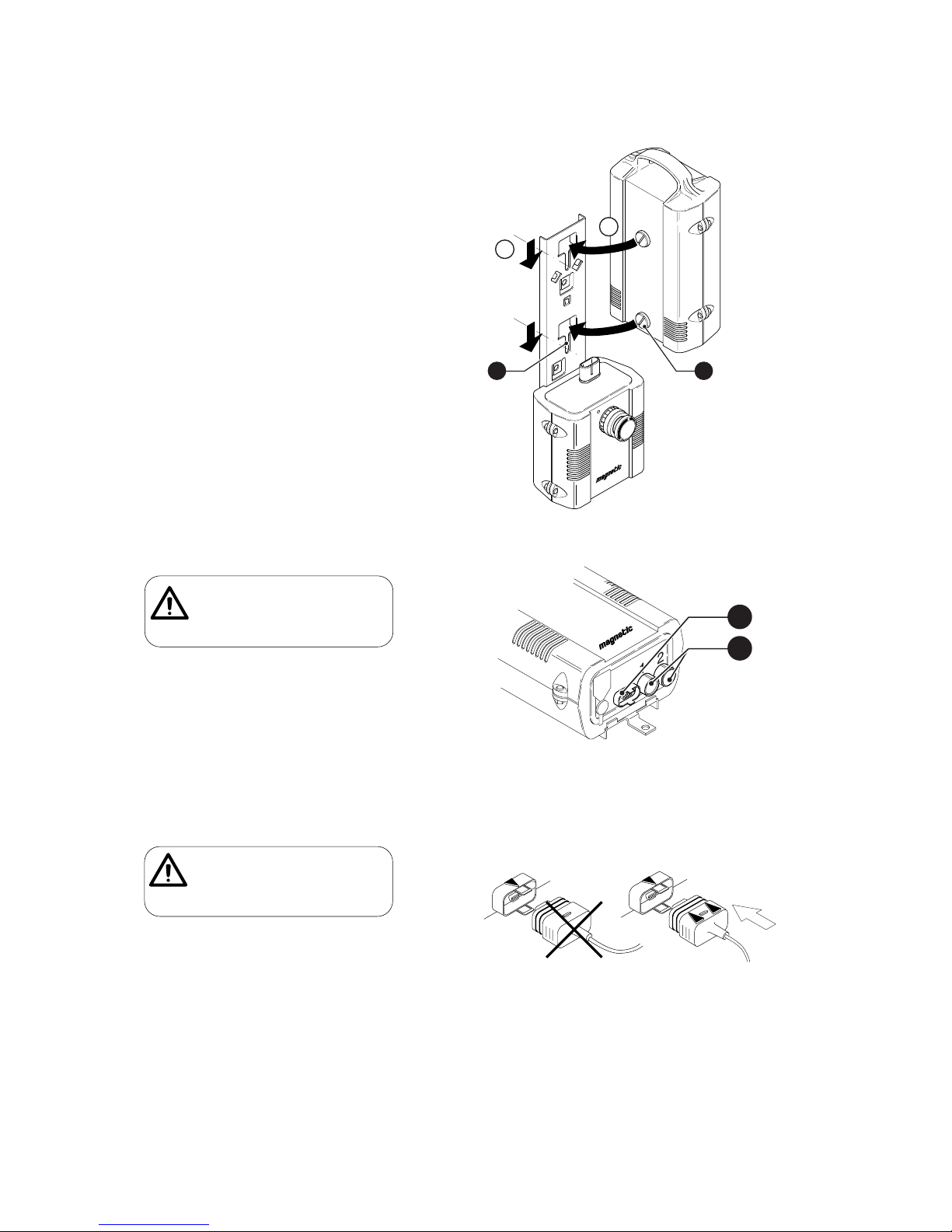
3.3 Inserting the battery pack
Insert the battery pack into the mounted control unit as described in Fig. 4.
Ensure that the cams
c are pushed right into the guides d. A locking spring on the
rear of the system carrier fixes the battery pack to the control unit.
c
d
e
fg
Fig.3 – Positions MCU1
Fig.2 – Mounting the control unit
A ventilation hole is provided in the battery
pack to allow gases to escape from the battery. The ventilation hole must not be damaged, removed or painted over.
Allowing liquid to penetrate the units and
blocking the ventilation is dangerous!
Ensure that the control unit is free of
mechanical tension and does not vibrate.
February 2008 For your nearest Distributor, call 1-800-694-4525 14
Technical instructions Control unit Mobilette
531e2931_0101 Magnetic – The Linear Drives Company™ page 5/11
3.4 Connecting the actuator and the control device
Connecting the control device
Insert the D-SUB plug of the control device into the corresponding socket n on the
control unit. (Fig. 5)
The cables are strain-relieved and sealed by means of the cast cams when plugged
into the socket. The cams engage in the retaining clips.
The control device used depends on the requirements of the system manufacturer.
1
2
Fig. 5 – Connections
All cables must be secured so that no forces
act on the control unit plugs. Plugs which are
poorly aligned may become loose and damage the control unit.
B
A
2 1
Fig. 4 – Inserting the battery pack
Fig. 6 – Inserting the control device plug
Ensure that the plugs are inserted with the
correct alignment, otherwise the device
socket can be damaged. Ensure the plug type
is correct (arrows must be on top)
February 2008 For your nearest Distributor, call 1-800-694-4525 15
Technical instructions Control unit Mobilette
531e2931_0101 Magnetic – The Linear Drives Company™ page 6/11
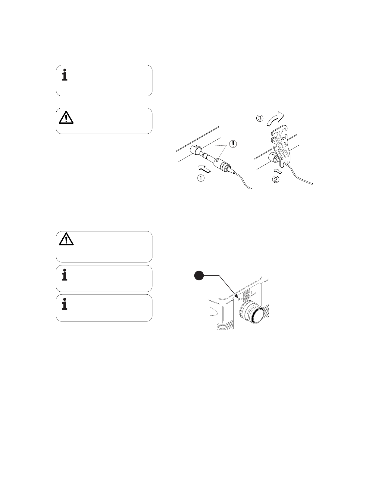
Connecting the actuator(s)
Insert the actuator plug into the corresponding socket o on the control unit (Fig. 5).
Then proceed as follows:
c Insert the plug (the sealing rings must not be visible)
Ensure that the groove on the plug is aligned with the mark on the control unit.
d Use the special plug disassembling tool No. 140375 to turn the plug approx. 30°
to the right up against the stop in order to lock it in position.
Repeat steps
c to d if you wish to connect an (optional) second actuator.
Otherwise, the actuator output which is not used is closed with a watertight blanking
plug at the factory. This plug must not be removed.
3.5 Startup
Charging the battery
The battery charging process is started when the mains adapter / mains cable is
plugged in, or the battery pack is fitted in place while the mains adapter / mains cable
is plugged in.
An LED (Fig. 8,
c) indicates the battery’s charge state
LED yellow Batteries are being charged, mains voltage connected.
LED green Batteries are fully charged, mains voltage connected.
LED unlit Mains voltage not connected.
Current consumption at full load
During commissioning, measure the actuator’s maximum current consumption at full
load. It must not exceed the value specified on the type plate of the linear actuator.
Higher current consumption means that the linear actuator is overloaded and may be
damaged.
An integrated overcurrent cut-off automatically deactivates the actuator if the current consumption is too great.
Fig. 7 – Inserting the actuator plug
Batteries must only be charged in well-ventilated rooms. The gases resulting from the
charging process are dangerous.
Do not charge the batteries in damp environments!
If the charging cycle lasts more than 20
hours, the battery or control unit is faulty.
Remove the mains adapter from the socket.
(See also 5.1 Maintenance)
Lightly lubricate the plug sealing rings with
Klübersynth VR-252, Magnetic order No.
R50014.
The use of other lubricants can damage sealing rings and the plastic housing.
Ensure that the groove on the plug is aligned
with the mark on the housing.
Otherwise, the plug cannot be connected
properly.
1
Fig. 8 – LED for battery charge status
During charging, any lifter controlled by the
MOBILETTE must not be used.
Wait until the charging process is over before
using the MOBILETTE.
February 2008 For your nearest Distributor, call 1-800-694-4525 16
Technical instructions Control unit Mobilette
531e2931_0101 Magnetic – The Linear Drives Company™ page 7/11
4 Instructions for use
4.1 Controlling an actuator
The actuator is controlled directly using buttons × and Ø on the control device:
Button × The actuator extends.
Button Ø The actuator retracts.
When the button is pressed, the LED on the control device lights up green.
The battery status can be checked as follows during any motor movement via an LED
on the control unit (Fig. 8,
c):
LED unlit Batteries are ready for operation.
LED flashes yellow Batteries must be charged, since they are
currently only charged to around 20%
A beep is heard The battery capacity is less than 20%, but there is still suf
ficient capacity for at least a double stroke. The batteries
must be charged immediately, otherwise the actuator's
deep-discharge protection will block further use! (See also
5.7 Troubleshooting)
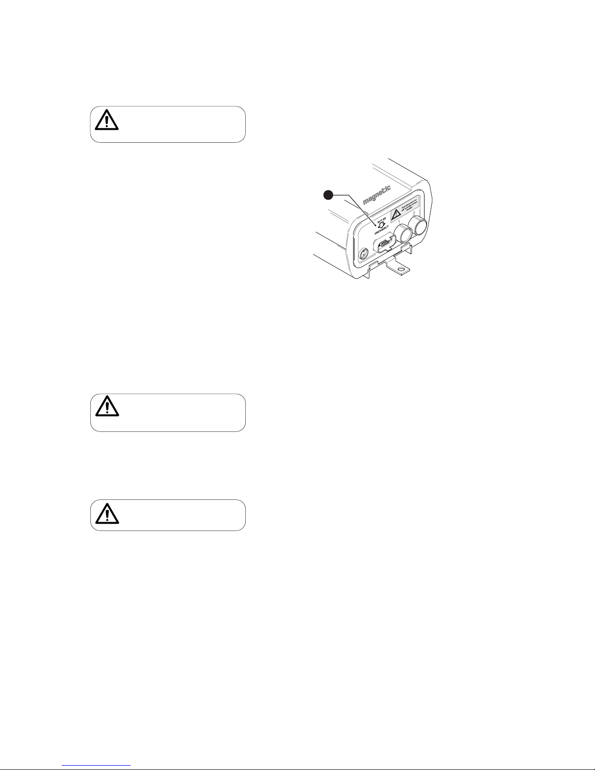
4.2 EMERGENCY STOP function
Pressing the EMERGENCY STOP button interrupts the power supply to the actuators
and causes the actuator to stop immediately. The EMERGENCY OFF switch should only
be used in cases of immediate danger.
Pressing the EMERGENCY STOP
Press the red button (A)
The button engages. The actuator stops and can no longer be controlled by the control
device while the "EMERGENCY STOP" button is locked in position.
Unlocking the EMERGENCY STOP
Turn the red button in the direction of the arrow. (B)
The "EMERGENCY STOP" button is unlocked. The actuator can be controlled as before.
B
A
Fig. 9 – EMERGENCY OFF
Only use the Mobilette with charged batteries. Operation with empty batteries is not
possible (not even if you connect the
MOBILETTE to the mains).
February 2008 For your nearest Distributor, call 1-800-694-4525 17
Technical instructions Control unit Mobilette
531e2931_0101 Magnetic – The Linear Drives Company™ page 8/11
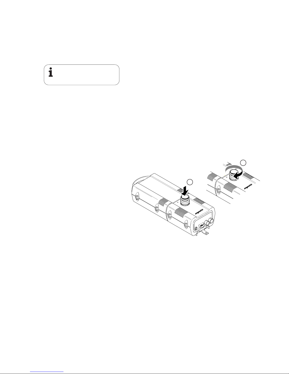
4.3 "Emergency Lowering" (option)
In contrast to the EMERGENCY STOP button, the "Emergency Lowering" option is
intended for when faults occur. A faulty control unit can be bypassed using the
"Emergency Lowering" button. This allows electrical lowering (retraction) of the actuator.
This is only possible for actuators on channel 1.
Pressing "Emergency Lowering"
Press the yellow button (see Fig. 10, c)
The faulty control unit must then be sent to Magnetic AG, Liestal for repair.
5 Care and maintenance
5.1 Maintenance
The control unit and the battery pack must only be opened and maintained by Magnetic Customer Services. Please contact Magnetic AG, Liestal.
Recharge flat batteries as soon as possible. This will increase their service life. When
in storage, batteries should be recharged every 6 months.
The service life of the batteries depends on the load and the charge status. It can last
up to 5 years.
Replacements for damaged or worn-out batteries and faulty charging devices should
be obtained from Magnetic AG, Liestal.
Changing the battery pack
Remove the battery pack by pulling the handle (with sufficient force to counteract the
stop spring). The new battery pack can then be inserted as described in chapter 3.3.
5.2 Functional checks
The following functions should be checked periodically - depending on the frequency
of use:
Mechanical damage
The plastic housing must be checked at least every six months for mechanical damage
(cracks).
Periodically check sealing edges for damage. The sealing rings of the control device
plugs and motor plugs must be checked for damage before each union and exchanged
if necessary.
Power cut-off
Check the power cut-off regularly while extending the actuator to an end position. On
reaching the end position, the control unit must deactivate the actuator without the
button on the control device being released. When the power is cut, a click is heard in
the control unit and the actuator motor stops running.
1
Fig. 10 – „Emergency Lowering”
Only batteries and charging units approved
by Magnetic must be used.
If defects are discovered, the MOBILETTE
must be taken out of service. Please send it to
Magnetic AG Liestal for repair.
Operators of the MOBILETTE must be familiar
with the difference between "EMERGENCY
OFF" and the (optional) "Emergency Lowering" functions.
February 2008 For your nearest Distributor, call 1-800-694-4525 18

Technical instructions Control unit Mobilette
531e2931_0101 Magnetic – The Linear Drives Company™ page 9/11
Battery display / deep-discharge protection
To check the function of the battery display, place a discharged battery pack in the
Mobilette control unit and press one of the buttons on the control device.
If the battery is empty, the yellow LED will flash when a button is pressed.
Now press a button on the control device until an audible signal indicates the battery's deep-discharge protection. After this signal, it must once again be possible to
retract the actuator.
If the battery is completely empty when it is placed into the control unit, the audible
deep-discharge protection signal will sound.
"EMERGENCY STOP"
Test the EMERGENCY STOP function by pressing the "EMERGENCY STOP" button while
an actuator is being operated. The actuator must stop immediately. (See also 4.2)
5.3 Care
Protection from water, cleaning, disinfecting
The MCU1 has been manufactured according to protection class IPx4. Protection class
IPx3 applies to the MCU8 (MCU4).
Do not clean the control unit without properly connected actuators, control device,
sealed mains adapter and sealed actuator input (Fig. 11, Pos. and ‚) . The control unit
would be damaged by fluid entering it.
Maximum cleaning / drying temperature = 65°C!
If the unit becomes dirty, the housing should best be cleaned immediately in order to
prevent the accretion of residues!
Use a damp cloth and water for manual cleaning. Add a little isopropyl alcohol if necessary.
5.4 Warranty
Assuming that the operating conditions are complied with and units have no mechanical damage, a warranty of 12 months from the date of delivery will apply for all
mechanical and electrical components.
Batteries are not covered by this warranty.
5.5 Disposal
The control unit components and actuators may be returned to Magnetic AG, Liestal,
for disposal.
Damaged or worn batteries and chargers should only be replaced by the Magnetic
Service Department or trained personnel.
Special precautions are to be observed for
the ML 0111/87. Washing water with chemical additives must be pH neutral. Excessively acidic or alkaline washing water can
permanently damage the metal and plastic
components of the control unit.
Hand-held and mechanical high-pressure
steam cleaners must not be used. For manual disinfection, only isopropyl alcohol
should be used.
1
2
Fig. 11 – Correctly closed control unit
Do not dispose of your batteries in domestic
waste.
Batteries must be recycled, disposed of properly or returned to Magnetic AG, Liestal.
February 2008 For your nearest Distributor, call 1-800-694-4525 19

Technical instructions Control unit Mobilette
531e2931_0101 Magnetic – The Linear Drives Company™ page 10/11
5.6 Technical data
See brochure No. 530D 2931.
The manufacturer reserves the right to adapt technical data to reflect technical
progress without prior notification. Magnetic AG, Liestal, will be pleased to provide
information about current specifications, possible changes or extensions.
5.7 Liability
In every case, the owner or operator of the unit shall be liable for its function if the
unit has been incorrectly installed, maintained or repaired by persons who are not
employed by the Magnetic Service Department or if the unit has not been handled in
accordance with its specified application.
Magnetic Aktiengesellschaft shall not be liable for any damage resulting from failure
to observe these instructions. These instructions shall not be regarded as an extension
of the warranty and liability terms set out in the Conditions of Sale and Supply
applied by Magnetic Aktiengesellschaft.
The product is not subject to the labelling requirements of the CE or EMC guidelines.
The required EMC measures for the end product must be met by its manufacturer, taking into account installation factors, wiring and control, and these must be checked
for compliance with the intended application.
Observance of these instructions is the responsibility of the manufacturer of the
machine or equipment.
February 2008 For your nearest Distributor, call 1-800-694-4525 20
 Loading...