

Vancare VanGo 600 User Manual

VANGO 600
Eva450EEL Eva600EEL
Eva450EML
REVISION HISTORY
REV.
DESCRIPTION
DATE
APPROVED
3
2
5
C
D
4
6
7
8
A
B
11
2
3
4
5
6
7
12
13
Manual - English
1
1. Boom
2. Mast
3. Handlebar
9
14
4. Battery pack
5. Emergency stop
6. Control box
7. Motor for base-width adjustment (model EE)
8. Rear castors with brakes
9. SlingBar with safety latch
10. Front castors
11. Emergency lowering
12. Motor/actuator for boom
13. Mast height adjustment
14. Base-width adjustment pedal (model EM)
8
10
SWL: 600Ibs
Mobile lift VanGo 600 has been developed to meet most lifting needs in combination with the right accessories. It
is a lift that can lift patients in a seated or supine position. VanGo600 is made largely of aluminum, which makes it
relatively light, considering the weight it can lift.
Functional inspection
Visual inspection
Inspect lift functions regularly. Check to ensure that material is free from damage.
Before use:
Ensure that the product is correctly assembled.
Check slingbar connection and safety latch function.
Check lift and base-width movement.
Check to ensure that the actuator is correctly installed.
Always read the manual
Always read the manuals for all assistive devices used during a transfer.
Keep the manual where it is accessible to users of the product.
The lift may only be used by persons who have received instruction in the operation of the lift.

Table of contents
Assembly .......................................................................................... 3
- Final inspection
..................................................................................... 4
Using the product ......................................................................... 5
- Important information
- Safe working load
- Charging batteries
................................................................................................ 6
- Handset
Base-width adjustmentt ......................................................................... 6
-
- Emergency stop
- Emergency lowering
................................................................................................. 7
- Brakes
- Trouble shooting
........................................................................... 5
................................................................................. 5
................................................................................. 6
.................................................................................... 7
.............................................................................. 7
.................................................................................... 8
Accessories .................................................................................... 9
Maintenance ..................................................................................10
Technical information ................................................................11
- Dimensions .....................................................................................12-13
2
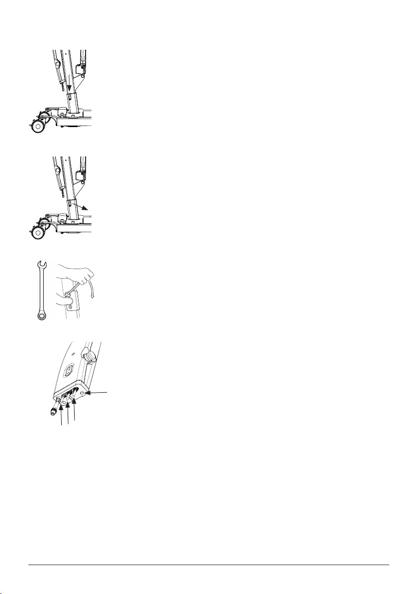
Assembly
Check to ensure that all components are included:
Mast with boom, lift motor, carry bar, control box and battery pack.
Base with motor and locking handle. Handset and cord.
Instructions, charger with cable and adapter for wall socket.
Place the mast in the base. There are three alternatives for adjusting the height of the
mast. Secure the mast with the locking handle.
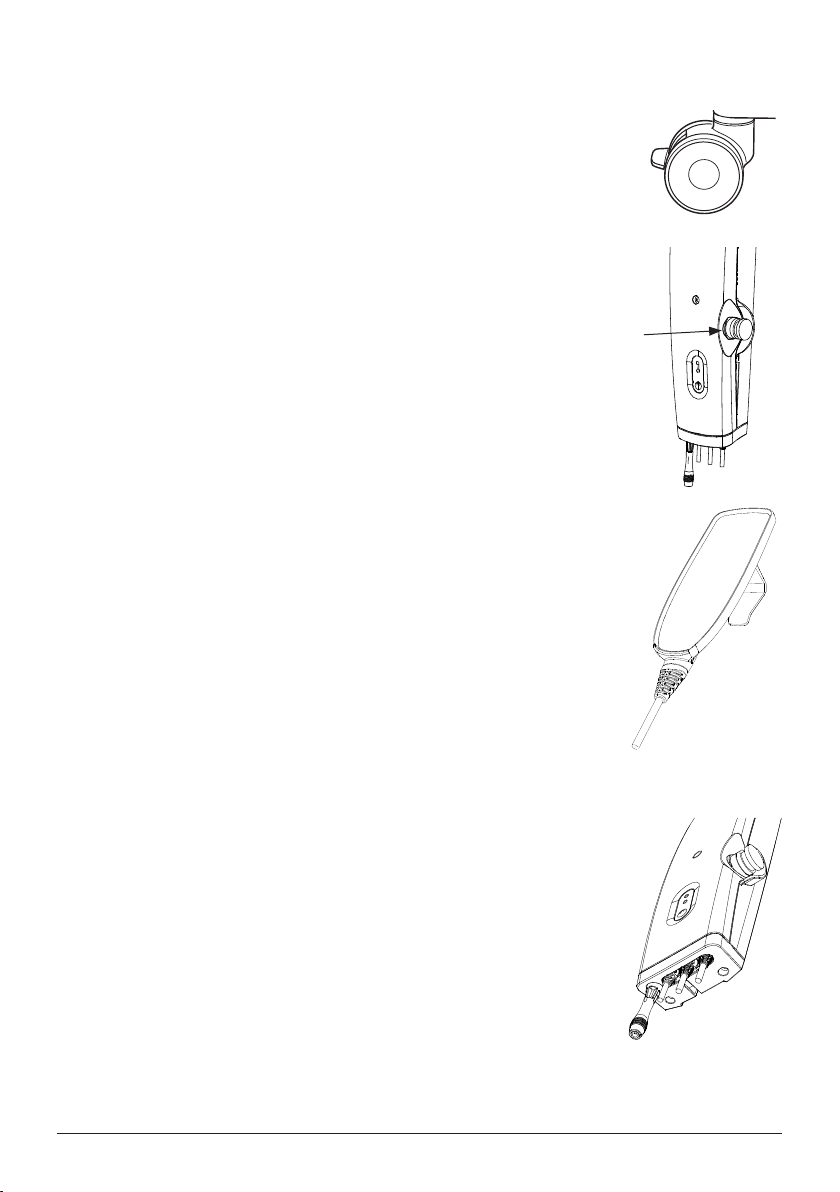
Mount handlebar with two wrenches.
Handset
Connect the cables to the c
1. Mount the cover for the cables using the two screws.
cover
for the
Release the emergency-stop mechanism and perform a final inspection (see final
cables
inspection).
1
ontrol box. Cable to actuator (motor on mast) to outlet
3
Final inspection
Check to ensure that no parts have been left in the packaging.
Inspect the lift for signs of wear and damage.
Check all four castor wheels and caster wheel locks.
Check all connections and fixtures including screws and bolts.
Check the emergency stop function by depressing the emergency stop, and then
pressing either the up or down button. If nothing happens when the up or down
buttons are pressed, the emergency stop is functioning properly.
Grasp the handset, press the up button and run the lift arm all the way up. Then, press
the down button and run the lift arm all the way down.
Test base-width adjustment function.
Test base-width adjustment function on the VanGo 400 by pushing down on the
respective pedals for widening and narrowing the base.
Test lift function by lifting a person (not a patient) using an approved sling. At the same
time, check the emergency lowering function with someone on the lift. See section on
Emergency lowering.
If the lift is functioning correctly, connect the charger and check to ensure that the
charging lamp on the control box lights up.
NOTE!
Before the lift is used for the first time, it must be charged for at least 4 hours. See
section on charging batteries.
Keep the manual where it is accessible to users of the product.
4

Using the product
Important Information
• The lift must be assembled according to the assembly instructions provided with the lift.
• The lift may only be used indoors and on a level floor.
• When lifting from the floor the rear wheels must always be locked to prevent the lift from rolling and colliding with the
patient’s head. Otherwise, the wheels should not be locked, so that the lift can align itself with the patient’s center
of gravity.
• Lifting accessories must be properly trial fitted and tested in relation to the patient’s needs and functional ability.
• Do not leave the patient unattended during a transfer situation.
• Under no circumstances may max. load be exceeded. See section on Safe working load.
• Never move the lift by pulling on the actuator!
• The lift must not come in direct contact with water.
• The lift must not be charged in a wet room.
• To ensure optimal function, the lift must be inspected regularly. See section on Maintenance.
• Warranty applies only if repairs or alterations are done by an authorized technician.
Do not push
Safe working load
Different products on the same lift system (lift unit, slingbar, sling, scales and other lifting accessories) may have different
allowable safe working loads. The lowest allowable safe working load always determines the safe working load of the
assembled system. Always check the safe working loads for the lift and accessories before use. Contact your dealer if
you have any questions.
5
 Loading...