

VANDER-LIFT II
For your nearest Distributor call, 1-800-694-4525
1
TM
Models: B450, B450 with scale, B600 and B600 with scale
OPERATING MANUAL
VANDER-LIFT II™ B450 VANDER-LIFT II™ B600
VANCARE, INC.
1515 First St
Aurora, NE 68818
1.800.694.4525
www.vancare.com

Table of Contents
1
November 2017
For your nearest Distributor call, 1-800-694-4525
1
Diagram and Features
VANDER-LIFT II™ B450 ..........................................................................3
UNI-FIT Sling ........................................................................................ 3
VANDER-LIFT II™ B600 ........................................................................ 4
Safety Information
Warning Symbol ....................................................................................5
Using the V
ANDER-LIFT II
With Other Manufacturer’s Equipment................................................... 5
Sling Care ............................................................................................. 5
Pre-use and Monthly Inspections .............................................................. 5
Leaving Slings Positioned Under Patients in Wheelchairs, etc ........................ 6
Staff Training ........................................................................................ 7
Patient Assessment Criteria for Transfers
TM
and UNI-FIT Sling
VANDER-LIFT II™ B450 Transfer Criteria ................................................... 8
VANDER-LIFT II™ B600 Transfer Criteria ................................................... 9
Two Methods of Connecting the UNI-FIT SLING ........................................ 10
Crossed
Loop Connection .................................................................. 10
Crossed Leg Support Connection........................................................ 10
Sizing and Positioning the UNI-FIT Sling .................................................. 11
Specialty Slings ................................................................................... 11
VANDER-LIFT II™ Transfer Procedures
Transfer from a Chair or Wheelchair........................................................ 12
Transfer from a Bed or Stretcher ............................................................ 14
Transfer from the Floor ......................................................................... 16
Transfer with the Amputee Sling............................................................. 18
VANDER-LIFT II
TM
Turning & Positioning with the Repositioning Sling ........... 20
Transport Procedure ............................................................................. 22
Toileting Procedure............................................................................... 24

Other Procedures
2
November 2017
For your nearest Distributor call, 1-800-694-4525
2
Emergency Stop Switch ........................................................................ 25
Base Adjustment.................................................................................. 25
Rear Caster Brakes............................................................................... 25
Emergency Lowering Switch .................................................................. 25
Charging the Batteries .......................................................................... 26
Pendant Switch Battery Indicator Lights .................................................. 26
Product Care
Sling Care ........................................................................................... 27
Monthly Sling Inspection ....................................................................... 27
Monthly VANDER-LIFT II™ Inspection ..................................................... 27
Cleaning the VANDER-LIFT II™ .............................................................. 28
Factory Service and Ordering Replacement Parts ...................................... 28
Further Questions ................................................................................ 28
VANDER-LIFT II™ Slings Ordering Information
UNI-FIT Slings ..................................................................................... 29
Bathing Slings ..................................................................................... 29
Amputee Slings.................................................................................... 30
Re-positioning Slings ............................................................................ 30
Sling Options ....................................................................................... 31
Monthly VANDER-LIFT II™ Inspection Checklist..................................... 32
Monthly VANDER-LIFT II™ Sling Inspection Checklist ............................ 34
Optional Built-in or Hanging VANDERSCALE®
Built-in VANDERSCALE® ....................................................................... 36
Operation, Calibration
Hanging VANDERSCALE® IMS ............................................................... 37
Installation, Operation, Calibration, Safety Alert, Installation of Bushing
Hanging VANDERSCALE® SR ................................................................. 39
Installation, Operation, 825 VST System Specifications,
Battery Replacement, Safety Alert, Installation of Bushing
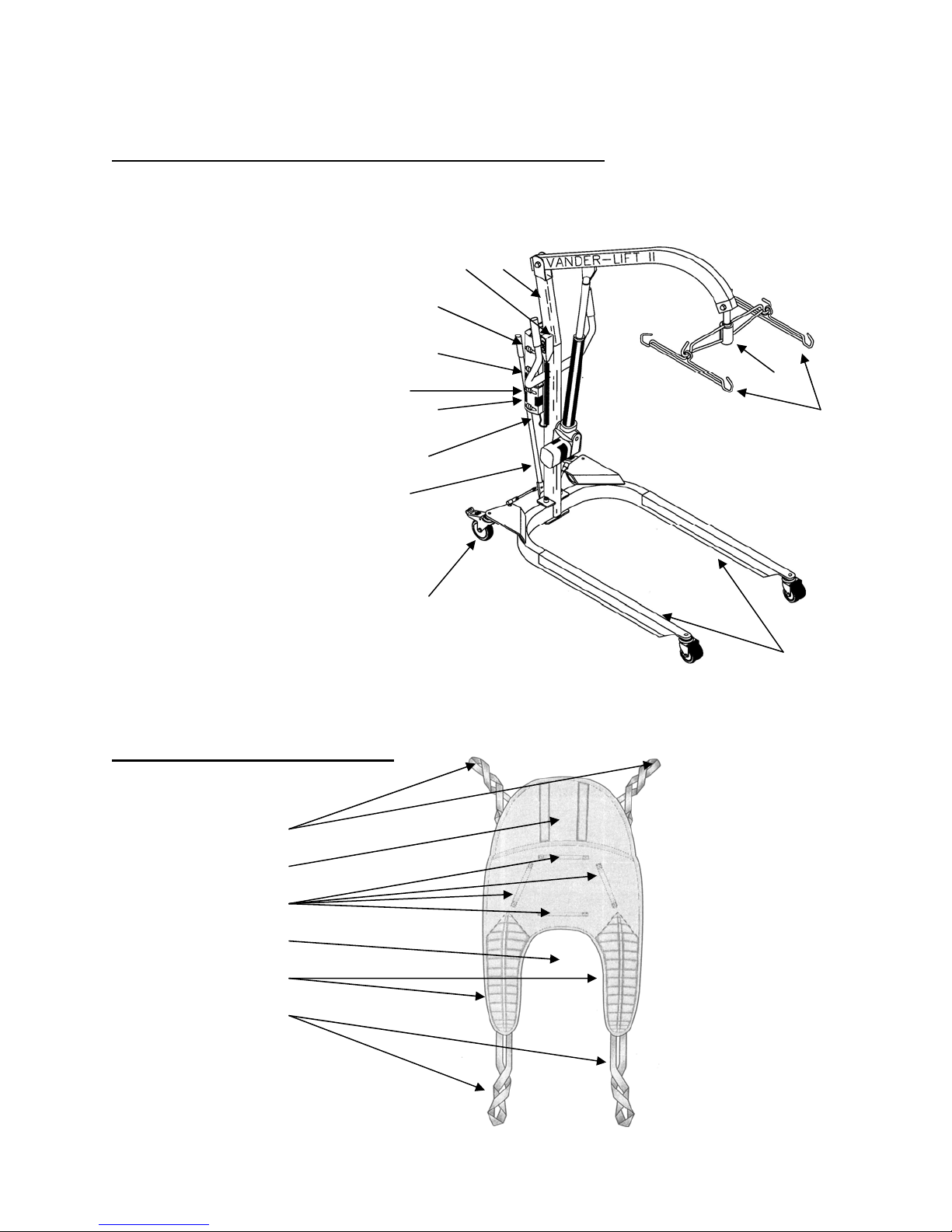
Diagram and Features
3
November 2017
For your nearest Distributor call, 1-800-694-4525
3
VANDER-LIFT II™ B450 Pound Lifting Capacity
1. Lift base
2. Locking rear caster brakes
3. Shift bar
4. Emergency lowering
switch (on bottom of
control box)
5. Emergency stop switch
6. Control box
7. Battery indicator lights
8. Rechargeable battery
9. Pendant switch
10. Mast
11. Hanger Bar Assembly
12. Hanger Rods
6
3
9 10
8
7
5
4
11
12
UNI-FIT Sling Features
Shoulder Loops
Head Support
Stabilizing
Horseshoe Area
Leg Supports
Leg Support Loops
2
1
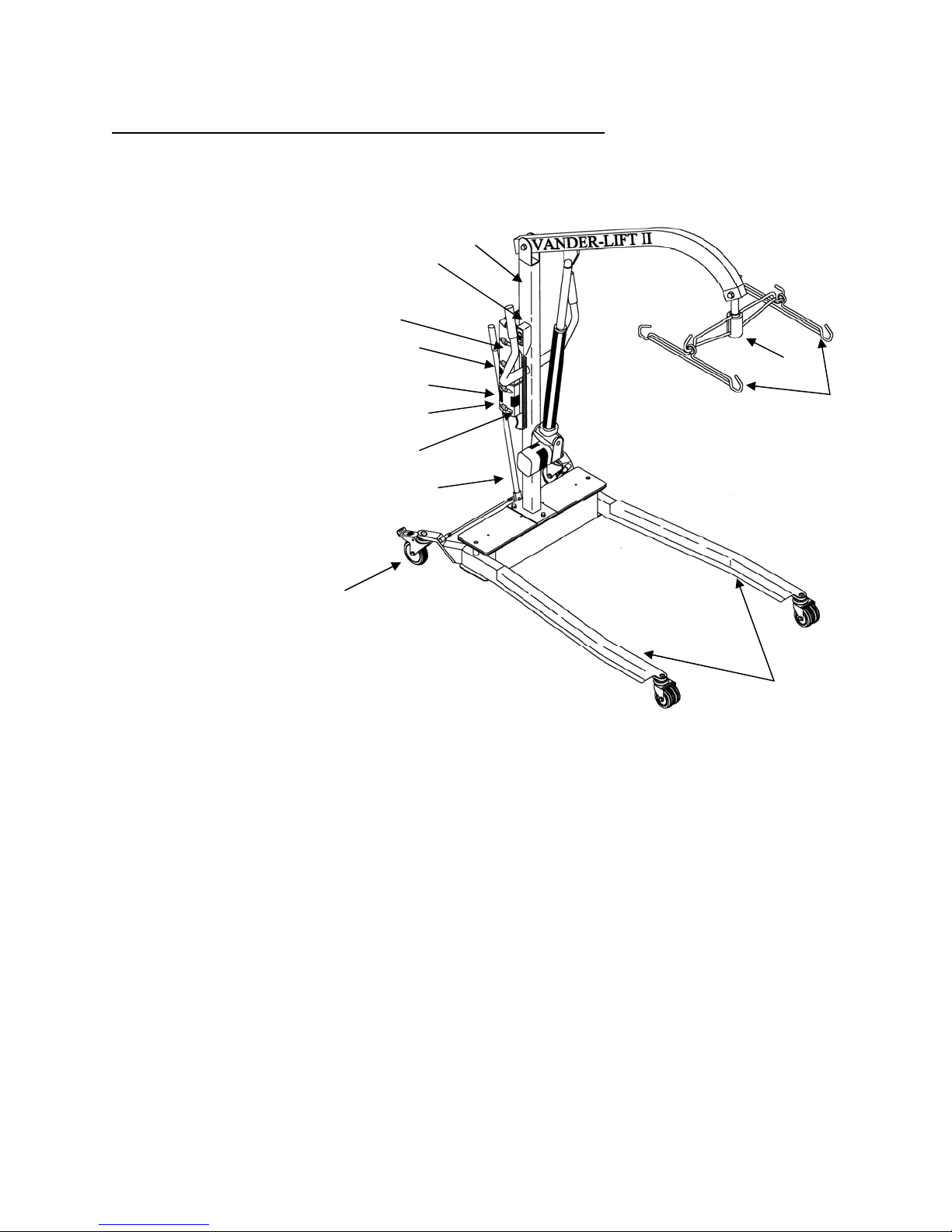
VANDER-LIFT II™ B600 Pound Lifting Capacity
4
November 2017
For your nearest Distributor call, 1-800-694-4525
4
1. Lift base
2. Locking rear caster
brakes
3. Shift bar
4. Emergency lowering
switch (on bottom of
control box)
5. Emergency stop switch
6. Control box
7. Battery indicator lights
8. Rechargeable battery
9. Pendant switch
10. Mast
11. Hanger Bar Assembly
12. Hanger Rods
8
7
5
4
10
9
6
3
11
12
2
1
Safety Information
5
November 2017
For your nearest Distributor call, 1-800-694-4525
5
Warning Symbol
A warning symbol is used in this manual to alert the user to important safety
information. Make sure your staff understands the meaning of the warning symbol
and follows the instructions that follow it.
Using the VANDER-LIFT IITM and VANDER-LIFT IITM Slings
with Other Manufacturer’s Equipment
WARNING
VANDER-LIFT II™ slings may be used with the VANDER-LIFT II™ only. Using other
manufacturer’s patient lifts with VANDER-LIFT II™ slings is also prohibited.
Sling Care
When slings are soiled or contaminated, they should be wash
or warm water only.
Wash/Dry Instruction
1) Standard VANCARE Sling: Slings may be tumble-dried on the “delicate” temperature
cycle in the dryer. If the dryer in your facility does not have a “delicate” cycle, slings
should be hung to air dry.
2) “C” Cloth Sling: Water Temperature of 167° F (75° C). Do not bleach. Air dry or dry at
temperature below 167°. Inspect with each use.
3) “H” Cloth Sling: Water temperature of 200° F (93° C). Do not bleach. Air dry or dry at
temperature below 200°. Inspect with each use.
WARNING
Bleach MAY NOT BE USED as it can weaken the stitching and fabric. It is important
that the Laundry Department is told how to care for slings correctly.
ed with mild detergent in cold
Pre-Use and Monthly Inspections
VANCARE lifts are designed and manufactured to meet or exceed the safety requirements
for patient care equipment. In addition, they have been tested and listed by a nationally
recognized testing laboratory, MET Labs., to insure their safety. It is important, however,
that you know that materials can fail due to normal wear caused by use over time. Doing
the inspections described below will help your facility make sure that lifts and slings are
kept in safe working condition and that potential problems are noted before hazardous
conditions result.

WARNING
6
November 2017
For your nearest Distributor call, 1-800-694-4525
6
Before each patient transfer, it is important for staff to inspect the VANDER-LIFT II™ to
make sure no parts are missing or overly worn and that all parts work correctly. If a
problem is noted, the lift should not be used until qualified maintenance staff has made
repairs.
It is also required that qualified m
aintenance staff inspect the lift at least monthly for
missing parts and excessive wear that might cause the lift to fail. A permanent record of
each of these inspections and repairs made should be kept by the facility. (See Monthly
VANDER-LIFT II™ Inspection Checklist at the back of this manual.)
WARNING
Before each patient transfer, the sling must also be inspected for signs of damage, for
loose and missing stitching, and for tears and excessive wear that might cause it to fail.
If a sling is damaged or overly worn, it must be thrown away and replaced with an
undamaged sling.
It is important that qualified maintenance staff inspect all VANDER-LIFT II’s™
monthly
It is also required that a nurse or professional rehabilitation staff member inspects all
VANDER-LIFT II™ slings for the above types of damage at least monthly. A permanent
record of each of these inspections and action taken should be kept by the facility. (See
Monthly VANDER-LIFT II™ SLING Checklist at the back of this manual.)
WARNING
It is important that a nurse or professional rehabilitation staff member
inspects all VANDER-LIFT II™ slings monthly.
Leaving Slings Positioned Under Patients in Wheelchairs, etc.
There are times when leaving the sling under a patient while he or she is seated in a
wheelchair or chair would promote patient comfort and would enable staff to provide care.
Before this can be done, however, the patient’s posture must be evaluated by a nurse or
professional rehabilitation department staff member to see if leaving the sling under the
patient might contribute to the patient sliding out of, or falling off of, a wheelchair or chair.
Secondly, the patient’s clothing, the sling fabric, and the surface of the chair or wheelchair
must be assessed for slipperiness.
WARNING
If leaving the sling under the patient places the patient at risk of sliding out of, or falling
off of, the chair or wheelchair, the sling may not be left under the patient.

Staff Training
7
November 2017
For your nearest Distributor call, 1-800-694-4525
7
After the VANDER-LIFT II™ has been received from VANCARE, Inc., a manufact
urer’s
representative will provide initial in-service training for your staff. Before using the
VANDER-LIFT II™ to transfer patients, all staff must be trained and authorized to use the
VANDER-LIFT II™. If additional training is needed, contact your local VANCARE distributor.
A DVD demonstrating transfer techniques and VANDER-LIFT II™ care was sent to the facility
with the lift. This video can be used, along with “hands on” training led by a nurse or
professional rehabilitation staff member who has been designated as your facility’s
mechanical lift trainer, as part of your facility’s mechanical lift education program. Only staff
members who have been trained according to the procedures in this manual, by a
manufacturer’s representative or by a nurse or professional rehabilitation staff member
designated as your facility’s mechanical lift trainer, be allowed to use the VANDER-LIFT II™.
WARNING
Watching the DVD without “hands on” training DOES NOT QUALIFY AS TRAINING. Staff
members who have seen the video but who have not had “hands on” training described
above ma
y not use the VANDER-LIFT II™.
Patient Assessment Criteria for Transfers
8
November 2017
For your nearest Distributor call, 1-800-694-4525
8
Transfer Criteria for the VANDER-LIFT IITM B450
WARNING
Before using the VANDER-LIFT II™ B450, patients must be assessed by the facility's
professional nursing or professional rehabilitation staff to determine which patients are
suitable for transfer with the VANDER-LIFT II™ B450, which VANDER-LIFT II™ transfer
technique to use, which size sling is appropriate, and the number of staff members
necessary to transfer each patient.
WARNING
Although one person can perform patient transfers, certain patients or situations may
require the help of one or more additional staff members. For example, patients with
unpredictable behavior due to dementia may require additional help if their behavior
poses risk of injury to themselves or to staff members, or patients being transported in
the VANDER-LIFT II™ with a VANDERSCALE outside of the patient’s room.
The above information must be recorded in the patient’s record and must be
communicated to the staff.
1) The Patient Must:
a) Have no injuries or medical conditions that might be aggravated by the VANDER-LIFT
II™ transfer procedure
b) Weigh less than 450 pounds
2) The Patient May:
a) Be non-weight bearing or unpredictably able to bear weight in his or her legs
b) Be unable to follow simple directions
c) Be seated or lying on the floor
d) Have loose muscles with little tone
e) Have a single or double leg amputations
f) Use an abduction pillow between the knees during transfers
g) Have unpredictable, resistive, or combative behavior
as long as the patient has
been assessed first for the appropriate type of sling, for the safest method of
connecting the sling to the hanger bar hooks, and as long as enough staff members
are present to prevent the patient from injuring himself, herself or the staff.

Transfer Criteria for the VANDER-LIFT II
9
November 2017
For your nearest Distributor call, 1-800-694-4525
9
TM
B600
WARNING
Before using the VANDER-LIFT II™ B600, patients must be assessed by the facility's
professional nursing or professional rehabilitation staff to determine which patients are
suitable for transfer with the VANDER-LIFT II™ B600, which VANDER-LIFT II™ transfer
technique to use, which size sling is appropriate, and the number of staff members
necessary to transfer each patient.
WARNING
Although one person can perform patient transfers, certain patients or situations may
require the help of one or more additional staff members. For example, patients with
unpredictable behavior due to dementia may require additional help if their behavior
poses risk of injury to themselves or to staff members, patients being transported in the
VANDER-LIFT II™ with a VANDERSCALE outside of the patient’s room.
The above information must be recorded in the patient’s record and must be
communicated to the staff.
3) The Patient Must:
a) Have no injuries or medical conditions that might be aggravated by the VANDER-LIFT
II™ transfer procedure
b) Weigh less than 600 pounds
4) The Patient May:
a) Be non-weight bearing or unpredictably able to bear weight in his or her legs
b) Be unable to follow simple directions
c) Be seated or lying on the floor
d) Have loose muscles with little tone
e) Have a single or double leg amputations
f) Use an abduction pillow between the knees during transfers
g) Have unpredictable, resistive, or combative behavior
as long as the patient has
been assessed first for the appropriate type of sling, for the safest method of
connecting the sling to the hanger bar hooks, and as long as enough staff members
are present to prevent the patient from injuring himself, herself or the staff.
Two Methods of Connecting the UNI-FIT Sling to the VANDER-LIFT
10
November 2017
For your nearest Distributor call, 1-800-694-4525
10
IITM
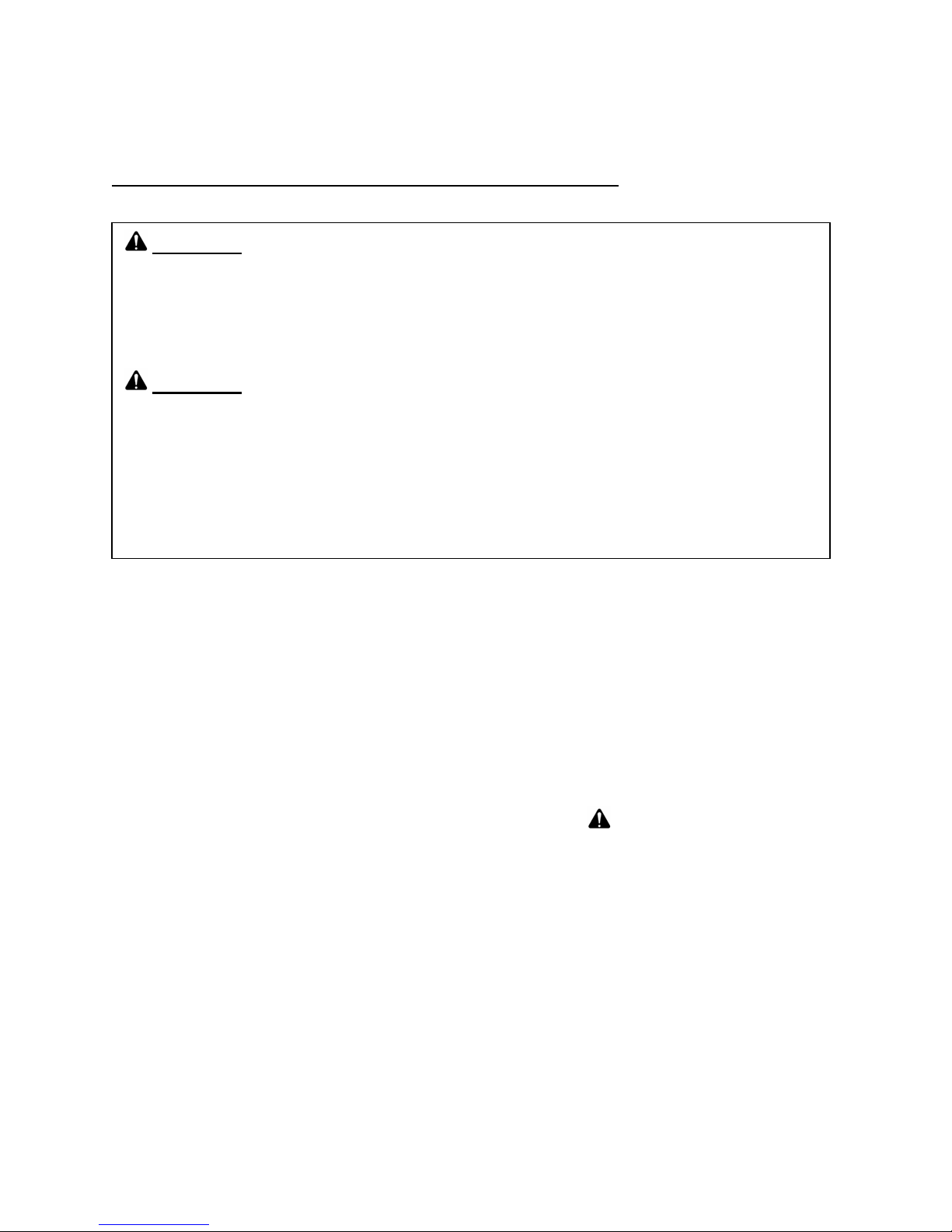
METHOD ONE: Crossed Loop Connection
Cross the leg loops for one leg support through the leg loop closest to
the leg support on the other side of the sling. This method of
connecting the sling to the lift is comfortable for many patients. The
patient may be transferred in a sitting, half-lying, or lying position.
1) The Patient Must:
a) Have predictable, cooperative behavior (patients with
dementia who have resistive or combative behavior during
transfers SHOULD NOT be transferred in this manner)
b) Have normal to rigid muscle tone
c) Have no injuries or medical conditions that might be
aggravated by the crossed loop connection transfer
d) Be able to separate the knees comfortably during transfers
2) The Patient May:
a) Have one leg amputated below the knee, as long as the other
leg is intact. (Patients who have had one or both legs
amputated above the knee should be transferred in an lying or
half-lying position with an amputee sling.)
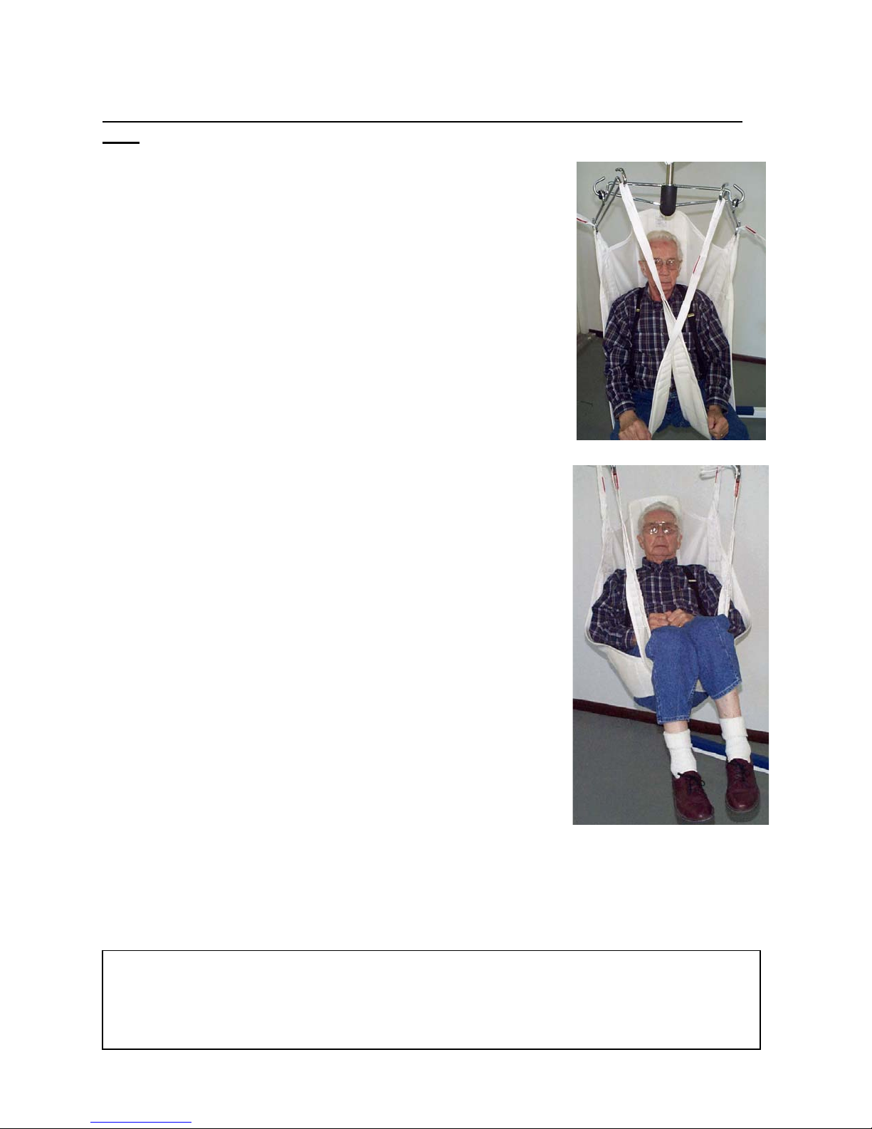
METHOD TWO: Crossed Leg Support Connection
Cross one leg support under both of the patient’s legs then cross the
other leg support under both of the patient’s legs. The patient may be
transferred in a sitting, half-lying, or lying position. When transferring
patients who have loose muscles with little tone, it is safest to transfer
them in a lying position.
1) The Patient Must:
a) Have behavior that does not pose risk of injury to
himself, herself or to staff during “crossed leg support
transfers”. (Examples of patients who have behavior that
might make “crossed leg support transfers” risky are patients
who bend forward while in the sling or patients who attempt
to climb out of the sling during transfers.
These patients should be transferred in a lying position with a
one piece amputee sling that has double safety belts.)
b) Have normal to rigid muscle tone. (Patients with loose
muscle tone who are at risk of sliding through the small space
at the horseshoe area of the sling should be transferred in a
lying position with a one piece double safety belt amputee
sling.)
c) Have at least one intact leg. If one leg has been
amputated, the amputation must be below the knee.
2) The Patient May:
a) Have unpredictable or uncooperative behavior, such as resistive or combative behavior,
as long as there are enough staff members present to prevent the patient from injuring
himself, herself, or the staff.
a) Have had recent hip surgery and require an abduction pillow between the knees for
transfer (as long as the physician’s other positioning requirements can be met).
*Patients who are able to stand with assistance, or who are unable to stand but can sit erect; can
be transferred safely with VANCARE’s companion products, the VERA-LIFT™ or the VERA-LIFT
II™. The VERA-LIFT™ and the VERA-LIFT II™ are designed to lift patients who require lower
levels of care. For information about the VERA-LIFT™, contact VANCARE, Inc. at (800) 694 –
4525, or call your local VANCARE representative.

Sizing and Positioning the UNI-FIT Sling
11
November 2017
For your nearest Distributor call, 1-800-694-4525
11
UNI-FIT SLINGS come in sizes from small to extra-large. When transferring a patient
using the VANDER-LIFT II™ and a UNI-FIT SLING, the sling should be l
ong enough to
fit from the patient’s coccyx to the top of, or a few inches above, the patient’s head and
wide enough for sling fabric to extend at least two inches in front of the patient’s
anterior shoulder. When the correct size sling has been determined for the patient, the
information should be documented in the patient’s record and the information should be
communicated to the nursing staff.
You can tell the size of the sling by looking at the color of the stabilizing handles on the
back of the sling. A reference guide for sling sizes is on the VANDER-LIFT II™ arm.
Small Black Stabilizing Handles Medium Red Stabilizing Handles
Large Blue Stabilizing Handles Extra Large Brown Stabilizing Handles
X X Large Green Stabilizing Handles
Specialty Slings
In addition to the standard UNI-FIT SLING, VANCARE manufactures UNI-FIT SLINGS with
fleece or STAPHtransferring patients with amputations, and re-positioning slings for turning and
repositioning large or difficult to move patients are also available. Contact your VANCARE
distributor for further information.
CHEK® lining. A number of other slings such as bathing slings, slings for
On rare occasions, a non-standard size or shape sling will meet an individual patient’s
transfer needs more safely. If you have a patient with special sling needs, contact your
VANCARE distributor.

VANDER-LIFT IITM Transfer Procedures
12
November 2017
For your nearest Distributor call, 1-800-694-4525
12
Transfer from a Chair or Wheelchair
1) Make sure you underst
and which size sling and which method of connecting the sling to
the hanger bars is to be used to transfer the patient.
2)
Inspect the VANDER-LIFT II™ and sling to make sure they are undamaged
and in good working order.
3) Make sure there is enough room in the patient’s room to do
the transfer. Move furniture
or other things that may be in the way. The required number of staff members must be
present.
4) Have the patient bend forward, helping as needed.
a) Some patients can pull themselves forward by holding onto chair or wheelchair arms,
by holding onto the edge of a sink, or by holding onto a raised side rail.
b) If a patient is stiff, or can’t help the staff member bend himself or herself forward,
additional staff may be needed to support the patient.
5) Place the sling behind the patient with the stabilizing handles on the outside of the sling
(facing away from the patient). Tuck the sling under the patient’s buttocks until the
bottom of the horseshoe area is over the patient’s coccyx. The center of the sling should
be over the patient’s spine with the head support at, or a few inches above, the top of
the patient’s head.
6) Lift one of the patient’s legs and pull the leg support under the leg, making sure not to
twist or fold the leg support.
7) Lay the leg support loops across the patient’s thigh.
8) Repeat the above steps for the patient’s other leg.
a) If the patient fits snuggly in the wheelchair, the sling can be placed under the patient
more easily if the staff members:
b) Help the patient to lean to one side.
c) On the side the patient is leaning away from, remove the wheelchair arm and pull
the leg support under the patient’s leg.
d) Replace the wheelchair arm
e) Help the patient to lean to the other side and repeat steps b – d.
9) Pull the shoulder loops to the side of the sling.
10) Move the VANDER-LIFT II™ into position with the hanger bar assembly about 15 inches
in front of the patient’s chin. Open the base to its widest position.
11) Connect the sling loops to the hanger bar hooks to transfer the patient in the desired
sitting, half-sitting or lying position and with the leg supports in the required position
(crossed loop or crossed leg support).
a) To transfer the patient in a sitting position, connect the closest shoulder loop to the
sling and the farthest leg loop from the sling to the hanger bar hooks.

b) To transfer the patient in a half-sitting position, connect the middle shoulder loop
13
November 2017
For your nearest Distributor call, 1-800-694-4525
13
and the one of the leg loops to the hanger bar hooks. (Each different loop
combination will change the patient’s position.)
c) To transfer the patient in a lying position, connect the farthest shoulder loop from
the sling and the closest leg loop to the sling to the hanger bar hooks.
12)
Double check the sling loop connection to the hanger bar hooks to make
sure the sling is securely attached with the loops in the bottom of the hanger
bar hooks.
13)
Leaving the caster brakes unlocked, lift the patient about 2 inches off of the
wheelchair seat, etc. and back the VANDER-LIFT II™ away. Leaving the brakes
unlocked will allow the lift to “walk forward” to center itself over the patient’s
center of gravity as it raises. This increases the stability of the lift. The only
time the brakes should be locked is if the patient is being lifted from a ramp or
some other sloping surface.
14) When the patient is away from the wheelchair, lower the patient so his or her feet are at
the top of the base of
the lift and,
slowly turning the lift, move the patient to
the desired location.
15) Raise the lift, if needed, so the patient will be about 2 inches above the bed, wheelchair
seat, etc.
16) Push the lift forward until the patient’s buttocks are positioned correctly over the bed or
at the back of the chair seat.
17) Lower the patient until the shoulder and leg loops are loose.
18) Unhook the sling loops from the hanger bar hooks.
19) Back the lift away and remove the sling.
20) Make sure the patient is safely positioned before removing the VANDER-LIFT II™ and
sling from the room.

Transfer from a Bed or Stretcher
14
November 2017
For your nearest Distributor call, 1-800-694-4525
14
1) Make sure you understand which size sling and which method of connecting the sling to
the hanger bars is to be used to transfer the patient.
2)
Inspect the VANDER-LIFT II™ and sling to make sure they are undamaged
and in good working order.
3) Make sure there is enough room in the patient’s room to do the transfer. Move furniture
or other things that may be in the way. Make sure the required number of staff
members are present.
4) Help the patient turn to his or her side.
5) Fold the sling and position it with the stabilizing handles on the outside of the sling
(facing away from the patient) and with the center of the sling over the patient’s spine.
The bottom of the horseshoe area should be over the patient’s coccyx and the top of the
head support should be at, or a few inches above, the top of the patient’s head.
6) Tuck the folded edge of the sling under the patient’s side.
7) Help the patient turn to the other side and straighten the sling making sure to smooth
out any wrinkles.
8) Help the patient turn onto his or her back. The patient should be centered on the sling.
9) Pull the shoulder loops to the side of the sling.
10) To position the leg supports:
a) Lift one of the patient’s legs and pull the leg support under the leg, being sure not to
twist or fold the leg support.
b) Lay the leg support loops across the patient’s thigh.
c) Repeat the above two steps for the patient’s other leg.
11) Move the VANDER-LIFT II™ into position with the hanger bar assembly about 15 inches
above the patient’s stomach. Open the base to its widest position.
12) Connect the sling loops to the hanger bar hooks to transfer the patient in the desired
sitting, half-sitting or lying position and with the leg supports in the required position
(crossed loop or crossed leg support).
a) To transfer the patient in a sitting position, connect the closest shoulder loop to the
sling and the farthest leg loop from the sling to the hanger bar hooks.
b) To transfer the patient in a half-sitting position, connect the middle shoulder loop
and one of the leg loops to the hanger bar hooks. (Each different leg loop
combination will change the patient’s position.)
c) To transfer the patient in a lying position, connect the farthest shoulder loop from
the sling and the closest leg loop to the sling to the hanger bar hooks.
13)
Double check the sling loop connection to the hanger bar hooks to make sure the
sling is securely attached with the loops in the bottom of the hanger bar hooks.

14) Leaving the caster brakes unlocked, lift the patient about 2 inches off of the bed or
15
November 2017
For your nearest Distributor call, 1-800-694-4525
15
stretcher and back the VANDER-LIFT II™ away. Leaving the brakes unlocked will allow
the lift to “walk forward” to center itself over the patient’s center of gravity as it raises.
This increases the stability of the lift. The only time the brakes should be locked is if the
patient is being lifted from a ramp or some other sloping surface.
15) When the patient is away from the bed or stretcher, lower the patient so his or
are at the top of the base of the lift and,
slowly turning the lift, move the patient
her feet
to the desired location.
16) Raise the lift, if needed, so the patient will be about 2 inches above the bed, wheelchair
seat, etc.
17) Push the lift forward until the patient’s buttocks are positioned correctly over the bed or
at the back of the wheelchair or chair seat.
18) Lower the patient until the shoulder and leg loops are loose.
19) Unhook the sling loops from the hanger bar hooks.
20) Back the lift away from the wheelchair, chair, etc. and remove the sling.
21) Make sure the patient is safely positioned before removing the VANDER-LIFT II™ and
sling from the room.

Transfer from the Floor
16
November 2017
For your nearest Distributor call, 1-800-694-4525
16
1) Make sure you understand
which size sling and which method of connecting the sling to
the hanger bars is to be used to transfer the patient.
2)
Inspect the VANDER-LIFT II™ and sling to make sure they are undamaged
and in good working order.
3) Make sure there is enough room to do the transfer. Move furniture or other things that
may be in the way. Make sure the required number of staff members are present.
4) Help the patient turn to his or her side.
5) Fold the sling and position it with the stabilizing handles on the outside of the sling
(facing away from the patient) and with the center of the sling over the patient’s spine.
The bottom of the horseshoe area should be placed over the patient’s coccyx and the
top of the head support should be at, or a few inches above, the top of the patient’s
head.
6) Tuck the folded edge of the sling under the patient’s side.
7) Help the patient turn to the other side and straighten the sling making sure to smooth
out any wrinkles.
8) Help the patient turn onto his or her back. The patient should be centered on the sling.
9) Pull the shoulder loops to the side of the sling.
10) Cross the leg supports under both of the patient’s legs. Place a pillow under the patient’s
head for comfort.
11) Open the base of the VANDER-LIFT II™ to its widest position.
12) Pick up the patient’s feet and slowly move the lift into position with the patient lying
diagonally between the legs of the lift. The patient’s knees should be close to the base of
the lift and the patient’s head should be toward the open end. The patient’s legs should
be over one of the legs of the lift and the lift should be as close to the patient as
possible.
13) Lower the lift as close to the floor as it will go.
14) Connect the farthest shoulder and leg support
loops from the sling to the hanger bar hooks so
the patient will be in a lying position.

15) Double check the sling loop connection to the hanger bar hooks to make
17
November 2017
For your nearest Distributor call, 1-800-694-4525
17
sure the sling is securely attached with the loops in the bottom of the hanger
bar hooks.
16)
Leaving the caster brakes unlocked, lift the patient until his or her feet are
at the top of the base of the lift and,
slowly turning the lift, move the patient
to the desired location. Leaving the brakes unlocked will allow the lift to “walk
forward” to center itself over the patient’s center of gravity as it raises. This
increases the stability of the lift. The only time the brakes should be locked is if
the patient is being lifted from a ramp or some other sloping surface.
17) Raise the lift, if needed, so the patient will be about 2 inches above the bed, wheelchair
seat, etc.
18) Push the lift forward until the patient’s buttocks are positioned correctly over the bed or
at the back of the wheelchair or chair seat.
19) Lower the patient until the shoulder and leg loops are loose.
20) Unhook the sling loops from the hanger bar hooks.
21) Back the lift away and remove the sling.
22) Make sure the patient is safely positioned before removing the VANDER-LIFT II™ and
sling from the room.

Transfer with the Amputee Sling
18
November 2017
For your nearest Distributor call, 1-800-694-4525
18
Patient Selection for Amputee Sling Transfer
Patients wi
th a single below the knee amputation can generally be transferred with the
standard UNI-FIT SLING. Patients with two leg amputations can safely be transferred using
the VANDER-LIFT II™ and the AMPUTEE SLING. Patients with leg amputations should be
transferred in a half-sitting or lying position.
Determining the Correct Amputee Sling Size
While the patient is in bed, help the patient turn to his or her side. Select the sling that fits
from the top of the patient’s head to:
a. The back of the knee (if the amputations are below the knee).
b. The bottom of the longest stump (if the amputations are above the knee).
Note the correct size sling on the patient’s record. * If patients have special sling needs,
contact your VANCARE distributor and a sling can be ordered to meet their specific needs.
1) Make sure you understand which size sling and which method of connecting the sling to
the hanger bars is to be used to transfer the patient.
2)
Inspect the VANDER-LIFT II™ and sling to make sure they are undamaged
and in good working order.
3) Make sure there is enough room in the patient’s room to do the transfer. Move furniture
or other things that may be in the way. Make sure the required number of staff
members are present.
4) Position the patient on the AMPUTEE SLING with the stabilizing handles on the outside of
the sling and the bottom of the sling hem:
a. behind the knee (if the amputation(s) is/are below the knee)
b. at the level of the longest stump (if the amputations are above the knee)
Fasten the optional chest and thigh safety belts.
5)
6) Move the VANDER-LIFT II™ into position with the hanger bar assembly so that it is:
a. about 15 inches in front of the patient at chin level, when the patient is seated.
b. About 15 inches above the patient’s stomach, when the patient is lying down.
7) Open the base of the lift to its widest position.
8) Connect the AMPUTEE SLING to the hanger bar hooks with the patient in
a. A half-sitting or lying position (if the patient has unilateral or bilateral below the knee
amputations)
b. Lying position (if the patient has unilateral or bilateral above the knee amputations)

9) Double check the sling loop connection to the hanger bar hooks to make
19
November 2017
For your nearest Distributor call, 1-800-694-4525
19
sure the sling is securely attached with the loops in the bottom of the hanger
bar hooks.
10)
Leaving the caster brakes unlocked, lift the patient about 2 inches off of the
bed or out of the chair and back the VANDER-LIFT II™ away. Leaving the
brakes unlocked will allow the lift to “walk forward” to center itself over the
patient’s center of gravity as it raises. This increases the stability of the lift.
The only time the brakes should be locked is if the patient is being lifted from a
ramp or some other sloping surface.
11) When the patient is away from the bed, wheelchair, etc., lower the patient so the
patient’s chest is at the height of the handgrips and, slowly turning the lift, move the
patient to the desired location.
12) Raise the lift, if needed, so the patient will be about 2 inches above the bed, wheelchair
seat, etc.
13) Push the lift forward until the patient’s buttocks are positioned correctly over the bed or
at the back of the wheelchair or chair seat.
14) Lower the patient until the shoulder and leg loops are slack.
15) Unhook the sling loops from the hanger bar hooks.
16) Back the lift away and remove the sling.
17) Make sure the patient is safely positioned before removing the VANDER-LIFT II™ and
sling from the room.

VANDER-LIFT II
20
November 2017
For your nearest Distributor call, 1-800-694-4525
20
TM
Turning and Positioning
with the Re-positioning Sling
Re-positioning slings may be left under patients as long as lying on the re-positioning sling
poses no risk for the patient.
Determining the Correct Re-positioning Sling Size
The re-positioning sling should be long enough to fit from 1 – 2 inches above the top of the
patient’s head to the bottom of the patient’s calf, or longer.
1) Make sure you understand which size re-positioning sling is to be used to turn and reposition the patient.
2) Inspect the VANDER-LIFT II™ and re-positioning sling to make sure they are
undamaged and in good working order.
3) Make sure there is enough room in the patient’s room to turn and re-position the
patient. Move furniture or other things that may be in the way. Make sure the required
number of staff members are present.
4) Help the patient turn to his or her side.
5) Fold the re-positioning sling and position it with the stabilizing handles on the outside of
the re-positioning sling (facing away from the patient) and with the center of the repositioning sling over the patient’s spine. The top of the re-positioning sling (the end
with the tag) should be an inch or two above the top of the patient’s head.
6) Tuck the folded edge of the re-positioning sling under the patient’s side.
7) Help the patient turn to the other side and straighten the re-positioning sling making
sure to smooth out any wrinkles.
8) Help the patient turn onto his or her back. The patient should be centered on the repositioning sling.
9) Pull the loops to the side of the re-positioning sling.
10) Move the VANDER-LIFT II™ into position with the hanger bar assembly about 15 inches
above the patient’s stomach. Open the base to fit around side rails, if needed.
11) Connect the upper, middle, and lower sling loops to the hanger bar hooks. (The hanger
bar assembly should be in the “H” position above the patient rather than in the “I”
position.)
12) The re-positioning sling loops closest to the patient’s head should be connected to the
hanger bar hook closest to the top of the re-positioning sling.
13) The middle set of re-positioning sling loops should be connected to the hanger bar
assembly hooks that will enable the patient to be lifted on a level plane. (The patient’s
head should be level with his or her middle and with the patient’s legs.)

14) The re-positioning sling loops closest to the patient’s feet should be connected to the
21
November 2017
For your nearest Distributor call, 1-800-694-4525
21
hanger bar hook closest to the foot of the re-positioning sling.
15) Double check the re-positioning sling loop connection to the hanger bar hooks to make
sure the sling is securely attached with the loops in the bottom of the hanger bar hooks.
16) Leaving the caster brakes unlocked, lift the patient about 2 inches off of the bed.
Leaving the brakes unlocked will allow the lift to “walk forward” to center itself over the
patient’s center of gravity as it raises. This increases the stability of the lift.
17) Check to see that the patient is level. If the patient’s head, middle and feet are not
level, lower the patient onto the bed and adjust the sling loops. Lift the patient about 2
inches off of the bed and check the patient’s position again.
18) When the patient is level, move the patient to the desired location over the bed, making
certain the patient will be positioned in the middle of the bed with the patient’s head in
the desired location when the patient is turned onto his or her side.
19) Lower the patient until the shoulder and leg loops are loose.
20) Unhook the re-positioning sling loops from the hanger bar hooks on the side you want to
turn the patient toward leaving the re-positioning sling loops on the side you want to
turn the patient away from attached to the hanger bar hooks. (If the re-positioning sling
is to be removed, fold the loops that have been unhooked from the VANDER-LIFT II™
and the edge of the re-positioning sling under the patient’s side.)
21) Raise the lift to turn the patient onto his or her side.
22) Remove the re-positioning sling if needed and support the patient in the desired position
with pillows or other positioning aids used in the facility.
23) Make sure the patient is safely positioned in the middle of the bed before removing the
VANDER-LIFT II™ and re-positioning sling from the room.

EMERGENCY Transport Procedure
R
22
November 2017
For your nearest Distributor call, 1-800-694-4525
22
FOR USE IN EMERGENCY SITUATIONS ONLY
Patient Selection for VANDER-LIFT II™ Transport
In order for a patient to be transported from one room to another safely in the VANDERLIFT II™, the patient must be able to remain positioned in a half-sitting or lying position
throughout the transport procedure. If a UNI-FIT SLING is used to transport a patient, the
leg supports must be crossed under both legs. An amputee sling may also be used.
WARNING
Patients whose behavior is unpredictable (ex. patients whose behavior can become
combative during transfers, patients who bend forward while in the sling, patients who
attempt to climb out of the sling during transfers, etc.) should not be transported using
the VANDE
Before Transport
The patient must be assessed by the professional staff and approved for transport
VANDER-LIFT II™ and this information should be documented and communicated to staff.
-LIFT II™.
with the
Transport Procedure
1) Make sure you understand which type and size sling, and which method of connecting
the sling to the hanger bars is to be used to transport the patient.
2)
Inspect the VANDER-LIFT II™ and sling to make sure they are undamaged
and in good working order.
3) Make sure there is enough room in the patient’s room to do the transfer. Move furniture
or other things that may be in the way. The required number of staff members must be
present. Although one person can transport the patient, certain patients or situations
require the help of one or more additional staff members. The presence of more than
one staff member increases safety when:
a. Transporting around corners.
i. Additional staff to hold onto sling handles when turning corners prevents the
patient from swaying thereby decreasing the possibility of tipping the VANDERLIFT II™.
ii. Additional staff walking in front of the VANDER-LIFT II™ can prevent the person
pushing the VANDER-LIFT II™ from colliding with people or things in the hallway
when turning corners.
b. Moving the VANDER-LIFT II™ through crowded areas.
Transporting patients in a VANDER-LIFT II™ with a VANDERSCALE requires
at least two staff members: one to push the lift and one holding onto the
sling’s stabilizing handles to keep the patient from swinging.
4) Position the patient on the sling.

5) Open the base of the VANDER-LIFT II™ to its widest position and move the lift into
23
November 2017
For your nearest Distributor call, 1-800-694-4525
23
position.
The base should remain in its widest position for transport. The base may be
closed when going through doorways but must be opened when the VANDERLIFT II™ has passed through the doorway.
6) Connect the sling to the hanger bar hooks. If a UNI-FIT SLING is used, the “crossed leg
support” method of connecting the sling to the lift should be used with the patient in a
half-sitting or lying position.
7)
Double-check the sling loop connection to the hanger bar hooks to make
sure the sling is securely attached with the loops in the bottom of the hanger
bar hooks.
8)
Leaving the caster brakes unlocked, lift the patient about 2 inches off the
bed or out of the chair and back the VANDER-LIFT II
TM
away. Leaving the
brakes unlocked will allow the lift to “walk forward” to center itself over the
patients’ center of gravity as it raises. This increases the stability of the lift.
The only time the brakes should be locked is if the patient is being lifted from a
ramp or some other sloping surface.
9) When the patient is away from the bed, wheelchair, etc., lower the patient so the
patient’s feet are at the top of the base of the lift.
10) Transport the patient to the desired location.

Toileting Procedure
24
November 2017
For your nearest Distributor call, 1-800-694-4525
24
In order to promote comfort for patients, to decrease physical stress for staff, and to speed
the toileting process for both, it is preferable if patients who prefer to wear pants wear
adaptive pants (pants with extended zippers on both side seams or a back flap that extends
from side seam to side seam) when they are no longer able to do standing transfers. Refer
to adaptive clothing catalogues for ideas. Contact VANCARE, Inc. if further assistance is
required.
Follow the VANDER-LIFT II™ “Transfer from a Wheelchair” procedure through
step “4” and continue with the following steps:
5) Adjust the patient’s clothing:
a) Spread the back of split back dresses or wrap around skirts.
b) Unzip side zippers and roll back of pants toward the patient’s buttocks or open back
flap of pants.
c) Untape the Brief, fold front side panels in and roll the back of the Brief toward the
patient’s buttocks so the clean outer surface of the Brief is touching patient’s clothing
OR
Unbutton elastic belt for button-type incontinence products OR
Roll patient’s underwear as close to the bottom of the patient’s buttocks as possible.
6) Position the sling behind the patient with the bottom of the sling approximately 1 inch
above the top of the rolled down pants and Brief, if used.
Continue with steps “6 – 13” of the VANDER-LIFT II™ “Transfer from a
Wheelchair” procedure, and then follow these steps:
14) Move the patient to the desired location in front of the toilet or commode with the back
of the patient’s legs positioned against the toilet or commode. Raise the patient, if
needed, to position the patient over the toilet or commode seat.
15) Adjust the patient’s clothing if necessary and, leaving the caster brakes unlocked, lower
the patient onto the toilet or commode seat.
16) Lock the caster brakes. Leave the sling attached securely to the lift with the lift in front
of the patient.
NEVER LEAVE THE PATIENT UNATTENDED DURING THE TOILETING
PROCEDURE.
17) After the patient has finished, lift the patient approximately 2 inches off of the toilet or
commode seat and help with peri care as needed.
18) Unlock the VANDER-LIFT II™ brakes and back the lift away.
19) Apply a clean incontinence product, if needed, and readjust patient’s cl
othing
.
To finish, continue with steps “14 – 20” of the VANDER-LIFT II™ “Transfer from a
Wheelchair” procedure.

Other Procedures
25
November 2017
For your nearest Distributor call, 1-800-694-4525
25
Emergency Stop Switch
A red emergency stop switch is located on the control box.
WARNING
If the hand control fails and the lift continues to raise or lower, press the emergency
stop switch on the control box to stop the lift.
Base Adjustment
The base of the VANDER-LIFT II™ should be open to its widest position for all transfers. The
base may be narrowed to go through doorway
cleared the door. To adjust the width of the base, stand behind the lift and grasp the top of
the spreader bar located at the rear of the lift. Adjust as follows:
Closed Move the spreader bar to the right hand position.
Half Open Move the spreader bar to the center position.
Open Move the spreader bar to the left hand position.
If your lift is equipped with an electric base, use the hand control to open and to close the
Rear Caster Brakes
legs instead of using the spreader bar.
s but must be opened after the lift has
Rear Caster Brakes
The VANDER-LIFT II™ is equipped with caster brakes on the rear wheels. To lock the
brakes, step down on
tab located on the top of each brake.
WARNING
The only time the brakes should be locked during transfers is when the patient is being
lifted from a ramp or some other sloping surface, or when toileting a patient with the
VANDER-LIFT II™.
the end of each brake tab. To release the brakes, push forward on the
Emergency Lowering Switch
WARNING
If the pendant switch fails, use the emergency lowering switch located on
the control box. To use it, press the down button with a pen or similiar object to
lower the lift. This switch should only be used in emergency situations when the
pendant switch fails.
Do not press on the hand held pendant switch buttons and the emergency
lowering switch at the same time.

Charging the Batteries
26
November 2017
For your nearest Distributor call, 1-800-694-4525
26
The VANDER-LIFT II™ is equipped with a charging cord, which charges the battery when
plugged into a standard 120 volt AC outlet. (See charging instructions on the lift.) Plugging
the lift into an outlet continuously for 7 hours, such as at night, will charge the batteries
enough for a full day of patient transfers. Emergencies can arise, however, which may
cause the staff to forget to plug the lift in (example: an emergency near the end of the
evening shift). In order to make sure the VANDER-LIFT II™ batteries will always be
charged, the lift may be plugged into an outlet whenever it is not being used. Either
charging procedure is acceptable. Optional wall charging station is suggested for continued
operation.
WARNING
Be sure to unplug the charging cord from the wall outlet before moving the VANDERLIFT II™ to prevent damage to the lift.
When
the VANDER-LIFT II™ is plugged in, the green “battery charge” light on the pendant
switch will be lit and you will hear a click, which indicate the batteries are being charged.
WARNING
For your protection, the lift will not work while it is charging.

Product Care
27
November 2017
For your nearest Distributor call, 1-800-694-4525
27
Sling Care
When slings are soiled or contaminated, they should be wa
or warm water only.
Wash/Dry Instruction
1) Standard VANCARE Sling: Slings may be tumble-dried on the “delicate” temperature
cycle in the dryer. If the dryer in your facility does not have a “delicate” cycle, slings
should be hung to air dry.
2) “C” Cloth Sling: Water Temperature of 167° F (75° C). Do not bleach. Air dry or dry at
temperature below 167°. Inspect with each use.
3) “H” Cloth Sling: Water temperature of 200° F (93° C). Do not bleach. Air dry or dry at
temperature below 200°. Inspect with each use.
WARNING
Bleach MAY NOT BE USED as it can weaken the stitching and fabric. It is important
that the Laundry Department is told how to care for slings correctly.
shed with mild detergent in cold
Monthly Sling Inspection
WARNING
A nurse or professional rehabilitation staff member must inspect slings at least once a
month for signs of damage, loose and missing stitching, and/or tears and excessive
wear that might cause them to fail. If a sling is damaged or overly worn, it must be
thrown away and replaced with an undamaged sling. A permanent record of each of
these inspections and action taken should be kept by the facility. (See Monthly
VANDER-LIFT™ Sling Inspection Checklist at the back of this manual.)
It is important that a nurse or professional rehabilitation staff member
inspects all slings monthly.
Monthly VANDER-LIFT IITM Inspections
WARNING
The VANDER-LIFT II™ must be inspected by qualified maintenance staff at least
monthly for missing parts and excessive wear that might cause the lift to fail. If a
problem is noted, the lift should not be used until repairs have been made by qualified
maintenance staff. A permanent record of each of these inspections and repairs made
should be kept by the facility. (See Monthly VANDER-LIFT II™ Inspection Checklist at
the back of this manual.)
It is important that qualified maintenance staff inspect all VANDER-LIFT
II™ units monthly.

Cleaning the VANDER-LIFT II™
y
28
November 2017
For your nearest Distributor call, 1-800-694-4525
28
When the VANDER-LIFT II™ gets soiled; it may be wiped clean with a damp cloth and mild
detergent.
WARNING
The VANDER-LIFT II™ should NEVER be cleaned in a shower, as water will damage the
electronics in the base of the lift. Damage from failure to follow this cleaning procedure
is NOT covered under warrant
.
Factory Service and Ordering Replacement Parts
For factory-authorized service or to order replacement parts, contact your local authorized
VANCARE Distributor.
Further Questions
If you have questions about any of the material cov
ered in this manual, contact your local
VANCARE Distributor. Your local distributor's name, address and phone number is located
on the back page of this manual. If you are unable to locate your local distributor, call
VANCARE directly using the phone number on the front cover.

VANDER-LIFT IITM Sling Ordering Information
29
November 2017
For your nearest Distributor call, 1-800-694-4525
29
UNI-FIT Slings (THE STANDARD SLING)
The UNI-FIT sling can be used to transfer patients who ar
e
unpredictably able to bear weight on their legs, who bear weight
too poorly to transfer safely with a sit to stand mechanical lift or
who are non-weight bearing. Patients need to have normal to
rigid muscle tone and have one intact leg. (Patients who bend
forward while being transferred in the UNI-FIT sling, patients who
attempt to climb out of the sling during transfers and patients
who have loose muscle tone and are at risk of sliding through the
small space at the horseshoe area of the sling should be
transferred with the one piece amputee sling that has double
safety belts.)
Material
Uni-fit slings are available in your choice of standard polyester, highheat polyester (which withstands temperatures up to 200°), and mesh.
You may also choose cool-heat polyester (which withstands
temperatures up to 167°) and has a non-absorbent coating on one side
for easy spot cleaning.
Sizing
UNI-FIT SLINGS should be long enough to fit from the bottom of the patient’s coccyx to the top of, or
a few inches above, the patient’s head and wide enough for sling fabric to extend at least two inches
in front of the patient’s anterior shoulder.
Size Length x Width Part Number
Small 34 x 35 inches 4-011000
Medium 37 x 36 inches 4-012000
Large 41 x 40 inches 4-013000
Ex-large 43 x 46 inches 4-014000
XX-large 54 x 52 inches 4-015000
XXX-large 70 x 66 inches 4-016000
Measurements are from the top of the head support to the
bottom of the horseshoe area.
Bathing Slings
Bathing slings are constructed of a polyester mesh fabric for
decreased water absorption and faster drying.
Material
Bathing slings are available in mesh only.
Size Length x Width Part Number
Small 34 x 35 inches 4-031000
Medium 37 x 36 inches 4-032000
Large 41 x 40 inches 4-033000
Ex-large 43 x 46 inches 4-034000
XX-large 54 x 52 inches 4-035000
Measurements are from the top of the head support to the bottom of the
horseshoe area.

Amputee Slings
30
November 2017
For your nearest Distributor call, 1-800-694-4525
30
The amputee sling can be used to transfer patients who
have unilateral or bilateral above t
patients with intact lower extremities who have loose muscle
tone and are at risk of sliding through the small space at the
horseshoe area of the UNI-FIT sling.
Material
Slings are available in your choice of standard polyester, high-heat
polyester (which withstands temperatures up to 200°), and mesh.
You may also choose cool-heat polyester (which withstands
temperatures up to 167°) and has a non-absorbent coating on one
side for easy spot cleaning.
Sizing
The amputee sling should be long enough to fit from behind the knees (if the amputation(s) are
below the knee), or from the bottom of the longest stump (if amputations are above the knee), to
the top of the patient’s head.
Size Length x Width Part Number
Small 55 x 36 inches 4-021022
Medium 59 x 36 inches 4-022022
Large 66 x 37 inches 4-023022
X-Large 75 x 44 inches 4-024022
Measurements are from the top of the head support to the bottom of the sling.
New Style Amputee Slings
he knee amputations and
The New Style Amputee can be used to transfer patients who
Re-positioning Slings
have unilateral or bilateral above the knee amputations and
patients with intact lower extremities who have loose muscle
tone and are at risk of sliding through the small space at the
horseshoe area of the UNI-FIT sling.
Material
Slings are available in your choice of standard polyester, high heat
polyester (which withstands temperatures up to 200°), and mesh.
You may also choose cool-heat polyester (which withstands
temperatures up to 167°) and has a non-absorbent coating on one
side for easy spot cleaning.
Sizing
The New Style Amputee Sling should be large enough to fit from behind the knees (if the
amputation(s) are below the knee), or from the bottom of the longest stump (if amputations are
above the knee), to the top of the patient's head. The sling should be wide enough to have at least 2"
past the patient's anterior shoulder. To estimate sizing of the New Style Amputee Sling,
measurements needed are from the TOP of the head to mid gluteal fold and around the waist or
widest part of the patient's body. Please note this is a general sizing application and final fitment will
need to be verified/checked and noted by responsible personnel before any type of transfer is
attempted.
Size Length x Width Part Number
Small 55 x 36 inches 4-021020
Medium 59 x 36 inches 4-022020
Large 66 x 37 inches 4-023020
March 2007 For your nearest Distributor, call 1-800-694-4525
X-Large 75 x 44 inches 4-024020
Measurements are from the top of the head support to the bottom of the sling.

REPOSITIONING SLINGS
31
November 2017
For your nearest Distributor call, 1-800-694-4525
31
Repositioning slings can be used for turning large or
difficult to move patients from side to side and for
repositioning them in bed.
Material
Slings are available in your choice of standard polyester, highheat polyester (which withstands temperatures up to 200°),
and mesh. You may also choose cool-heat polyester (which
withstands temperatures up to 167°) and has a non-absorbent
coating on one side for easy spot cleaning.
Size Length x Width Part Number
Small 48 x 35.5 inches 4-041000
Medium 54 x 42 inches 4-042000
Large 54 x 50 inches 4-043000
Ex-large 54 x 59 inches 4-044000
XX-large 53 x 69 inches 4-045000
Measurements are top to bottom (length) and side to side (width).
Sling Options
Slings can be manufactured with optional fleece or STAPH-CHEK® sewn in moisture proof
lining. Moisture proof STAPH-CHEK® slip on sling protectors are also available.
SPECIAL ORDERS
On rare occasions, a non-standard size or shape sling will meet an individual patient’s
transfer needs more safely. Contact your distributor for custom order requirements.
FOR INFORMATION ON CURRENT PRICING, OR TO PLACE AN ORDER, CONTACT
YOUR DISTRIBUTOR
WARRANTY INFORMATION
VANCARE back belts and slings are guaranteed for one year from the date of purchase for
defects in materials and manufacture. Damage caused by misuse or improper care is not
covered.

32
November 2017
For your nearest Distributor call, 1-800-694-4525
32

MONTHLY VANDER-LIFT II™ INSPECTION CHECKLIST
INSTRUCTIONS: Use one page for each VANDER-LIFT II™. Check each
blank as that item is inspected. Note date inspected, initials of
maintenance staff member who performed inspection and repairs or adjustments made in the “COMMENTS” column.
Serial Number of Lift
Year
JAN FEB MAR APR MAY JUN JUL AUG SEP OCT NOV DEC COMMENTS
Check nuts & bolts for
tightness
Inspect welds for cracks,
rusting & damage
Inspect hanger bar
welds & tolerance
(See diagram below)
Inspect wire connections
Check casters for
tightness/lint
Check battery voltage*
*24 volts if fully charged, approx. 12.0 volts if partially discharged (+ or - .5 volt). If voltage decreases by 4 – 5 volts, change the battery.
HANGER ROD DIAGRAM
Verify grommets and hanger rods are present and in working condition.
Please follow the maintenance and inspection procedures outlined in the product manuals and record accordingly.
Based on institutional average usage data, Vancare recommends that all lifts be replaced every ten years or sooner
based upon the facilities usage and the findings during regular use, maintenance and inspections.
33
November 2017
For your nearest Distributor call, 1-800-694-4525
33

34
November 2017
For your nearest Distributor call, 1-800-694-4525
34

MONTHLY VANDER-LIFT II™ SLING INSPECTION CHECKLIST
INSTRUCTIONS: All slings in the faci
lity must be checked monthly. Slings that are damaged or excessively worn must be removed
from service and replaced with undamaged slings. Check each blank as that item is inspected. Note the date inspected, the initials of
the nurse or professional rehabilitation department staff member who performed the inspection, and action taken, if any, in the
“CORRECTIVE ACTION” column.
YEAR
JAN FEB MAR APR MAY JUN JUL AUG SEP OCT NOV DEC CORRECTIVE ACTION
Total number of slings.
Is loose and/or missing
stitching present?
On slings with safety
belts, does Velcro or
plastic connector fasten
securely?
Are tears present?
Is excessive wear
present?
Is color fading on
stabilizing handles? *
Is the padding inside the
leg straps smooth? **
*If the color is fading on the stabilizing handles, this indicates the sling is being laundered with bleach or with a harsher detergent than is recommended. The sling must be
removed from service immediately and discarded as bleach or harsh detergent can weaken the fabric and stitching.
**If the padding inside the leg straps is bunched (no longer smooth), this indicates the sling has been dried in a hot dryer. The sling must be removed from service immediately
and discarded as too much heat can damage the sling.
35
November 2017
For your nearest Distributor call, 1-800-694-4525
35

36
November 2017
For your nearest Distributor call, 1-800-694-4525
36

Optional Built-in or Hanging VANDERSCALE®
37
November 2017
For your nearest Distributor call, 1-800-694-4525
37
Thanks to such features as push-button operati
on and automatic zeroing, optional built-in or
hanging VANDERSCALES® weigh residents with extraordinary ease and accuracy.
Built-In VANDERSCALE®
Operation
1.
To turn on the scale, press the “ON/ZERO” pad. The display will perform a startup
sequence, showing the firmware version (V 1.0) and the current battery voltage (b 6.7),
then settle on some weight.
2. Place the sling onto the spreader bar. Make sure that no part of the sling or spreaderbar is touching the floor or any object. Press the “ON/ZERO” pad to zero the display.
The display will show the word “Zero” while the pad is pressed, then will count down
from -3- to -0-.
3. Place the sling around the patient per the Lift Manufacturer’s instructions. Lift the
patient clear of all contact with the bed/chair. Read the patient’s weight on the scale
display. If the display turned off before lifting the patient, simply press the “ON/ZERO”
pad to turn the scale on and read the weight (be careful to press the “ON/ZERO” pad
only once to turn the scale on, or the display may be inadvertently zeroed while the
patient is in the sling).
4. To change the display unit from lb to kg or from kg to lb, press and hold the “LB/KG”
pad for approximately 3 to 4 seconds. The display will show the “conv” message then
blank and the unit enunciator will change from LB to KG or from KG to LB. Release the
“LB/KG” pad after the unit enunciator changes.
5.
To recall the last patient’s weight, the scale must first be turned on. Press the center of
the “VANCARE” logo to the left of the “ON/ZERO” pad on the front of the scale. The
display will show the message “rECL” then alternately flash between the stored weight
and the “rECL” message.
6. If the battery symbol appears, replace the battery with a AA alkaline battery. The
battery access cover is on the bottom of the scale.
Calibration
1. Should calibration be necessary, all that is required is a 25 lb precision weight (do NOT
use bags of flour or other packaged goods for weights - contact the Lift Manufacturer to
purchase precision weights).
2. To enter the calibration mode, first press and hold the “ON/ZERO” pad. While holding
the “ON/ZERO” pad press and hold the “LB/KG” pad. After approximately 3 seconds the
message on the display will change from “Zero” to CAL”. Release both pads at this time
and the display will show the “C 0” message.

3. Make sure the sling is empty and press the “ON/ZERO” pad. The indicator will count
38
November 2017
For your nearest Distributor call, 1-800-694-4525
38
down from -8- to -0- while taking readings and store the zero point. When finished,
the indicator will show the “C25” message.
Place a 25 lb test weight in the sling and press the “ON/ZERO” pad once again. The
4.
indicator will count down from -8- to -0- while taking readings and calculate and store
the span calibration. The indicator then automatically returns to the normal weighing
mode. Calibration is now complete.
Hanging VANDERSCALE® IMS
Installation
1. Attach the VANDERSCALE® to the VANDER-LIFT II
TM
per the Lift Manufacturer’s
instructions.
2. Hang the spreader-bar assembly from the VANDERSCALE® per the Lift Manufacturer’s
instructions.
Operation
1. To turn on the scale, press the “ON/ZERO” pad. The display will perform a startup
sequence, showing the firmware version (V 1.0) and the current battery voltage (b 9.0),
then settle on some weight.
2.
Place the sling onto the spreader bar. Make sure that no part of the sling or spreaderbar is touching the floor or any object. Press the “ON/ZERO” pad to zero the display.
The display will show the word “Zero” while the pad is pressed, then will count down
from -3- to -0-.
3.
Place the sling around the patient per the Lift Manufacturer’s instructions. Lift the
patient clear of all contact with the bed/chair. Read the patient’s weight on the scale
display. If the display turned off before lifting the patient, simply press the “ON/ZERO”
pad to turn the scale on and read the weight (be careful to press the “ON/ZERO” pad
only once to turn the scale on, or the display may be inadvertently zeroed while the
patient is in the sling).
4. To change the display unit from lb to kg or from kg to lb, press and hold the “LB/KG”
pad for approximately 3 to 4 seconds. The display will show the “conv” message then
blank and the unit annunciator will change from LB to KG or from KG to LB. Release the
“LB/KG” pad after the unit annunciator changes.
5. To recall the last patient’s weight, the scale must first be turned on. Press the center of
the “VANCARE” logo to the left of the “ON/ZERO” pad on the front of the scale. The
display will show the message “rECL” then alternately flash between the stored weight
and the “rECL” message.
If the battery symbol appears, replace the battery with a AA alkaline battery. The
6.
battery access cover is on the bottom of the scale.

Calibration
39
November 2017
For your nearest Distributor call, 1-800-694-4525
39
1. Should calibration be necessary, all that is required is a 25 lb precision weight (do NOT
use bags of flour or other packaged goods for weights - contact the Lift Manufacturer to
purchase precision weights).
2. To enter the calibration mode, first press and hold the “ON/ZERO” pad. While holding
the “ON/ZERO” pad press and hold the “LB/KG” pad. After approximately 3 seconds the
message on the display will change from “Zero” to CAL”. Release both pads at this time
and the display will show the “C 0” message.
3.
Make sure the sling is empty and press the “ON/ZERO” pad. The indicator will count
down from -8- to -0- while taking readings and store the zero point. When finished,
the indicator will show the “C25” message.
4. Place a 25 lb test weight in the sling and press the “ON/ZERO” pad once again. The
indicator will count down from -8- to -0- while taking readings and calculate and store
the span calibration. The indicator then automatically returns to the normal weighing
mode. Calibration is now complete.
Safety Alert!
It has been brought to our attention that the hanging VANDERSCALE to be installed on your
VANDER-LIFT II
TM
can become lodged on the boom, thereby causing inaccurate weights.
The potential also exists that when so lodged it may break the safety pin, thereby causing
the scale to unhook. THIS COULD CAUSE AN INJURY TO A RESIDENT AND/OR STAFF
MEMBER.
Shown below is a part called a bushing. This part is designed to help prevent this problem
from occurring.
Installation of Bushing / IMS & SR Scales
FLAT HEAD SCREW (Steps 1 & 3)
BUSHING (Step 2)
(Patent Pending)
Step 1: Use a standard screwdriver and remove flat head screw.
(See above)
Step 2: Slide Bushing into place as shown above.
Step 3: Repl
ace flat head screw and tighten firmly.

Hanging VANDERSCALE® SR
40
November 2017
For your nearest Distributor call, 1-800-694-4525
40
The 825VST Weight Module is a compact precision scale system designed for use with the
VANDER-LIFT II
TM
patient lift or other *approved lifter designs employing compatible
boom and hanger configurations.
Completely self-contained, the 825VST combines the latest in precision strain gauge
technology and microprocessor signal conditioning to provide stable, accurate and
repeatable weight data with a calibrated accuracy of 0.1%.
One Button Auto-Zero Electronics makes patient weighing quick and easy.
The 825VST derives its’ power from a single 9 volt lithium battery which will provide up to
3000 weight readings:
Installation
1. Attach the top hook of the 825VST Scale to the boom loop of the lifter making sure that
the hook is fully engaged.
2. IMPORTANT: Tighten Retainer Screw until fully engaged.
3. Attach the swivel bar to the bottom of the scale system then attach the selected sling.
Operation
1. Attach the scale system as described in the installation instructions. Make sure that
the hook is fully engaged in the loop and the retainer screw is properly
installed.
2. With the sling in place, press the “ZERO” button to set the system to zero. The digit “0”
will pan across the display for a few seconds then the display will read “0.0”.
3. Remove the sling (or stretcher), position the patient into the sling, and then reattach to
the swivel bar.
4. Carefully lift the patient. When the motion has stabilized, press the “WEIGH” button to
display the weight data.
NOTE: The display will automatically turn itself off after approx. 60 seconds to
conserve battery power. If the display turns off before you are able to view the
weight data, simply press the “WEIGH” button once again.
5. Carefully lower the patient after reading weight.
ALWAYS RE-ZERO THE SCALE SYSTEM BEFORE WEIGHING (step 3)
CAUTION
This device is intended to obtain patient weight during transfer (i.e. bed to chair). This
device is NOT intended for use during patient transport and should be removed in such
case.

825VST System Specifications
41
November 2017
For your nearest Distributor call, 1-800-694-4525
41
WEIGHT RANGE 453KG / 1000LB*
DISPLAY RESOLUTION 0.1KG / 0.1LB
ACCURACY 0.1% + /- 1 DIGIT OF READING
DISPLAY TYPE LIQUID CRYSTAL DISPLAY
SIZE 3” X 3” X 4”
WEIGHT 1 POUND
POWER SUPPLY 9-VOLT LITHIUM BATTERY
BATTERY LIFE APPROX. 3000 READINGS
*Do Not Exceed Lifter Capacity
Battery Replacement
A single AA battery powers the 825VST Scale System. This battery should provide
approximately *3000 readings before needing replacement.
When battery replacement is needed, an indicator will appear on the display. Simply
remove the two screws on the case to access the battery.
*3000 READINGS OBTAINED WITH 9-VOLT LITHIUM BATTERY
NOTE: The Load Cell contains no user serviceable components and should be serviced by
authorized personnel only. Any unauthorized tampering will void the warranty.
If you should have any questions or comments regarding the operation of the 825VST
please call your local distributor.
Safety Alert!
It has been brought to our attention that the hanging VANDERSCALE to be installed on your
VANDER-LIFT II
TM
can become lodged on the boom, thereby causing inaccurate weights.
The potential also exists that when so lodged it may break the safety pin, thereby causing
the scale to unhook. THIS COULD CAUSE AN INJURY TO A RESIDENT AND/OR STAFF
MEMBER.
Shown below is a part called a bushing. This part is designed to help prevent this problem
from occurring.
Installation of Bushing / IMS & SR Scales
FLAT HEAD SCREW (Steps 1 & 3)
BUSHING (Step 2)
(Patent Pending)
Step 1: Use a standard screwdriver and remove flat head screw.
(See above)
Step 2: Slide Bushing into place as shown above.
Step 3:
Replace flat head screw and tighten firmly.

VANDER-LIFT, VANDER-LIFT II & VANGO Skills Observation Assessment
42
November 2017
For your nearest Distributor call, 1-800-694-4525
42
Staff Member Observed ___________________________________________ Date _____________
PROCEDURE - DID THE EMPLOYEE:
Have the required number of staff members present?
Select the correct size sling?
Inspect the sling and lift for damage and proper operation?
If DAMAGED, did the employee get another lift/sling and notify charge nurse?
Correctly position the sling so that the bottom center of the sling is at the tailbone?
Perform environment assessment and move objects that would impede operation of lift?
Move the lift into position with the hanger bar in the “H” position in front of the resident and
the base properly opened?
Properly use the locking casters (locking only on “ramped surfaces”)?
Lower the lift using the Pendant Switch?
Connect the sling loops to the hanger bar hooks? Use the same loops on each side?
Double check the sling attachment to the lift?
Lift the resident only as high as necessary?
Moving the lifter with a patient in the sling? (1 person pushes lift, while the other controls the
resident, using the “hand-loops”.)
Lower the lift until the resident is sitting on the chair or lying on the bed?
Remove the sling loops from the hanger bar hooks, and prevent the hanger bars from coming in
contact with the patient?
Back the lift away from the resident and remove the sling?
Make certain the resident is safe and comfortable before leaving?
KNOWLEDGE – CAN THE EMPLOYEE:
Identify lifting capabilities (maximum weight)?
Identify location and use of Emergency Stop Switch?
Identify location and use of Emergency Lowering?
Identify location and use of Auxiliary Up/Down Switch?
Identify Low Battery Indicator light?
Demonstrate how and when to recharge batteries?
Properly use the Scale attachment?
Identify sling parts: head support, shoulder loops, leg supports, leg loops, stabilizing
handles?
Demonstrate ability to adjust angle of recline to maintain hip precautions?
Demonstrate transfer of patient, using Vander-Lift, Vander-Lift II and VanGo, from bed to
to chair, chair to bed, and floor to bed?
Demonstrate proper understanding of how to clean the sling and lift?
Refer to Operator’s Manual for more detailed description of transfer technique.
Pass Fail
Observations __________________________________________________________________
_____________________________________________________________________________
Observer’s Name _______________________________________________________________
Observer’s Signature ____________________________________________________________
 Loading...