

VANDER-LIFT™
MODELS 450, 600 & 1000
MAINTENANCE
MANUAL
ALL VANCARE PRODUCTS
ARE MADE IN THE U.S.A.
VANCARE,Inc. Phone: (800) 694-4525
1515 First Street Fax: (402) 694-3994
Aurora, Nebraska 68818 Email: LQIR@YDQFDUH.FRP

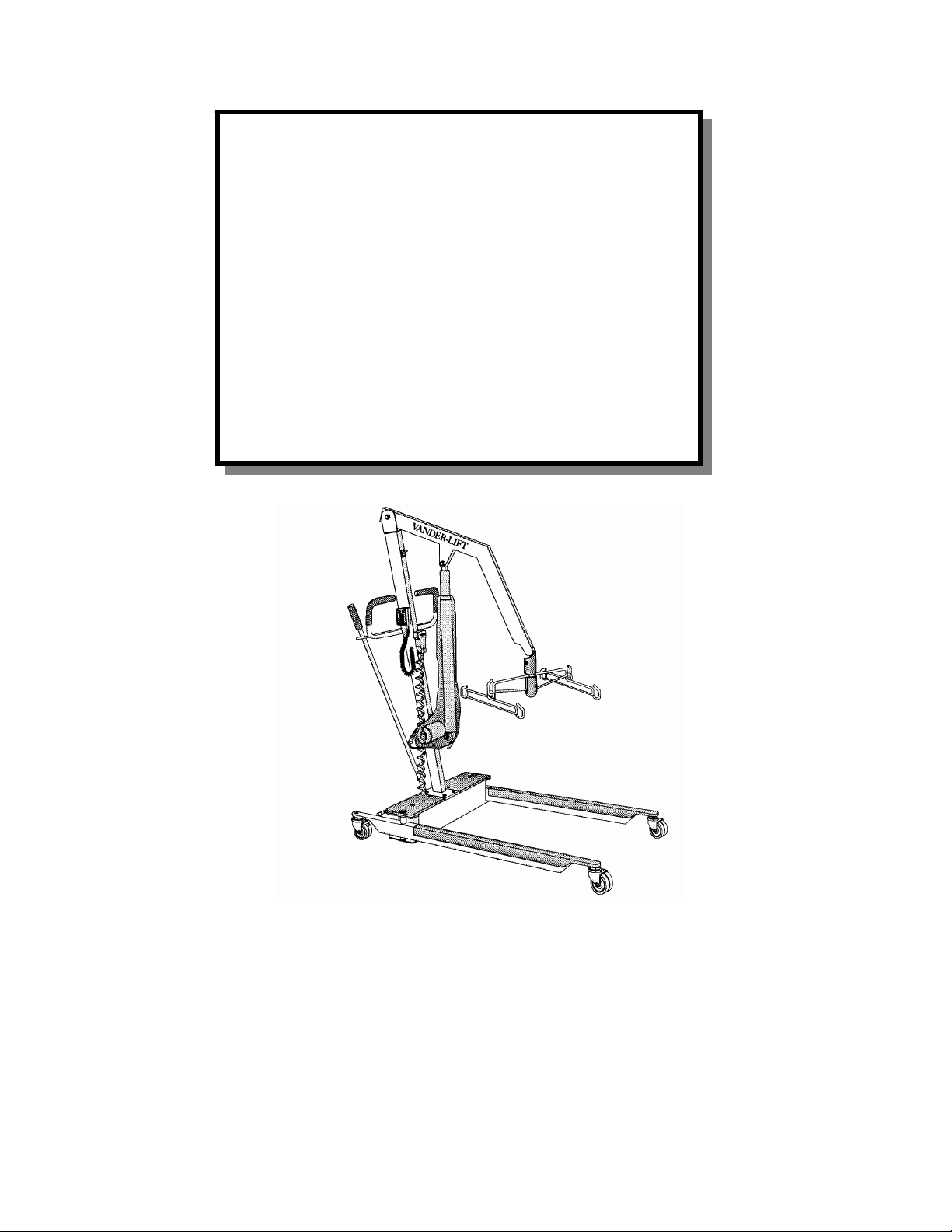
VANDER-LIFT
April 2014
For your nearest Distributor, call 1-800-694-4525
2
MODELS 450, 600 * 1000
MAINTENANCE MANUAL
TABLE OF CONTENTS
VANDER-LIFT DIAGRAM OF PARTS AND DESCRIPTIONS
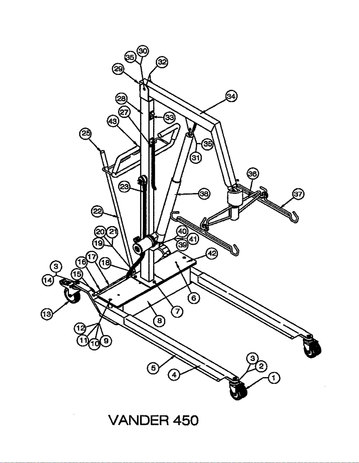
Vander-Lift 450 diagram, part numbers and descriptions Page 3-4
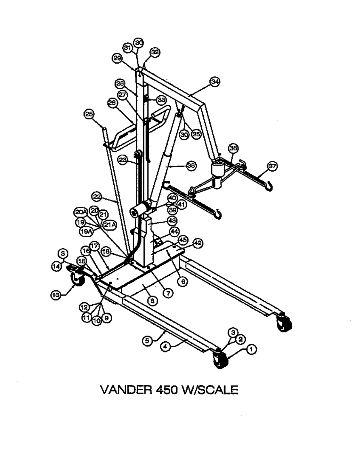
Vander-Lift 450 w/scale diagram, part numbers and descriptions Page 5-6
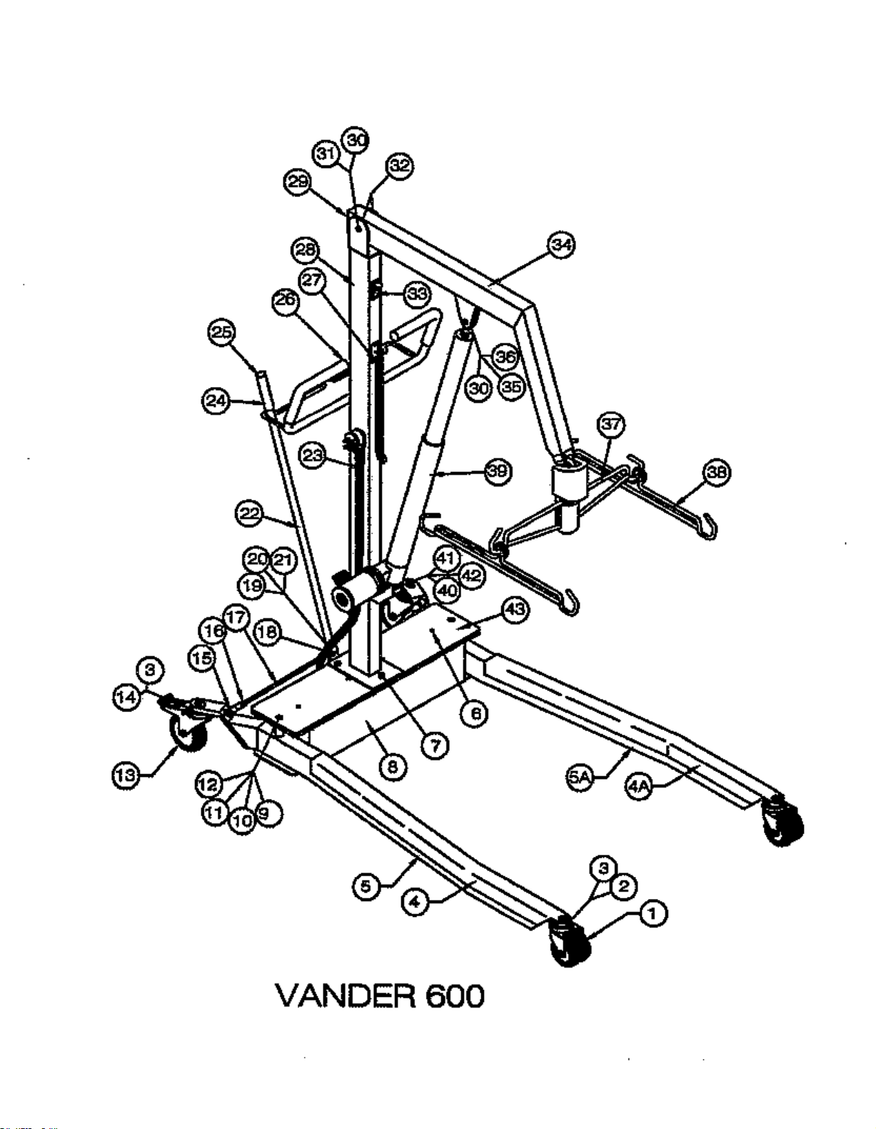
Vander-Lift 600 diagram, part numbers and descriptions Page 7-8
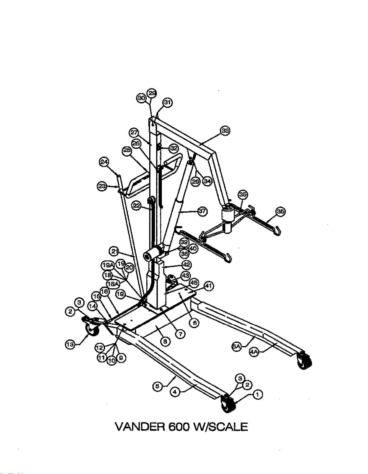
Vander-Lift 600 w/scale diagram, part numbers and descriptions Page 9-10
Vander-Lift 1000 diagram, part numbers and descriptions Page 11-12
ASSEMBLING LIFT
Tools needed to assemble your lift Page 13
Assembly Procedure Page 13-14
TROUBLE SHOOTING GUIDE
Problems, Solutions & Diagrams Page 15-22
MONTHLY VANDER-LIFT SLING INSPECTION SHEET Page 24
MONTHLY VANDER-LIFT INSPECTION SHEET Page 26
QUARTERLY MAINTENANCE CHECK
Tools needed for quarterly maintenance check Page 28
Quarterly Maintenance Page 28-29
For your nearest Distributor, call 1-800-694-4525
1
April 2014
For your nearest Distributor, call 1-800-694-4525
3

V-L LEG PROTECTORS CLEAR
OPTIONAL
VANDERLIFT 450
April 2014
For your nearest Distributor, call 1-800-694-4525
4
REF # PART # DESCRIPTION QTY REF # PART # DESCRIPTION QTY
1 MFG-9-523190 CASTER 3" NON-LOCK 2 35 MFG-6-000350 INDEX ARM (ZI
2 MFG-9-238120 3/8-16X1.25 F
3 MFG-9-263820 3/8-16 NYLON LOCKNUT 4 23 MFG-6-000055 HOSP PLUG W/AC CORD 1
4 MFG-4-900615
5 MFG-4-100010 V-
FG-
M
4-200010 V-L LEG (BLUE) 2
6 MFG-9-225750 1/4-20 X 3/
7 MFG-9-238100 3/8-16 X 1 GR 5 B0LT 3 28 MFG-4-100030 V-L TOWER (WHITE) 1
8 MFG-4-100020 V-L BASE (WHITE) 1 MFG-4-200030 V-L TOWER (BLUE) 1
MFG-4-200020 V-L BASE (BLUE) 1 *28 MFG-9-322039 VC CORD ASSEM (TAN) 1
*8 MFG-6-008000 24V CONTROL BOARD 1 *28 MFG-9-336450 E-STOP WIRE HARNESS 1
*8 MFG-9-270463 4-40X5/8 SH CAP (SS) 2 *28 MFG-9-370650 POWER CORD (MOTOR) 1
*8 MFG-9-270625 6-32X1/4 BH SH (SS) 2 *28 MFG-9-398956 WIRE 5&6 MICRO SWTCH 1
*8 MFG-9-270838 #8-32 X 3/8" PH-PH 2 *28 MFG-9-542400 1/2" GROMMET 5
*8 MFG-9-271075 #1O-24 X 3/4 MS 1
*8 MFG-9-290650 #6 INT
7 MFG-9-293807 3/8" SPLIT LOCK WASH 5 32
*
*
8 MFG-9-320650 CORD RESTRAINT 1 33
8 MFG-9-321510 BATTERY 12 VOLT 2 34 1
*
*8 MFG-9-351600 JUMPERS (BATTERY) 1
*
8 MFG-9-386630 FLAG TERM. .250 1
*8 MFG-9-386710 RING TERMINAL (BLUE) 2 35 MFG-9-265005 1/2 -20 JAM NUT 2
*8 MFG-9-387100 SPADE CONN
*8 MF
*8 MFG-9-570850 BATTERY PAD (UPPER) 1 38 MFG-4-520151 ACTUATOR, V-L 24V 1
*8 MFG-9-570860 BATTERY PAD (LOWER) 1 *38 MFG-4-930145 CRANK - EMERGENCY DN 1
*8 MFG-9-570870 BOARD PAD 1 *38 MFG-9-370660 MIC SWITCH/DOOR&LIFT 1
*8 SEW -6-000089 BATTERY STRAPS 1 *38 SEW -4-900171 V-L BOOT (BLK) 1
9 MFG-9-250050 1/2-13 X 5 1/4 HH G5-LEG 2 39 MFG-9-238125 3/8 X 1 1/4 SH BOLT 1
10 MFG-9-295040 WASHER .040/SS 2 40 MFG-9-263118 5/16-18 HEX NUT 1
11 MFG-9-295062 WASHER .062/SS 2 41 MFG-9-645500 HOSE 4 ACT. BUSHING 1
12 MFG-9-265008 1/2-13 NYLON JAM NUT 2 42 MFG-6-000522 PLASTIC LIDS 2
13 MFG-9-523120 CASTER 4" LOCKING 2 * MFG-9-261024 #10-24 LOCK NUT 2
14 MFG-9-238153 3/8-16X 1.5 FH SH/SS 2 * MFG-9-672020 PLASTIC MOUNT-MICRO 1
15 MFG-6-583650 CUT TIE ROD ENDS 2 * SEW-6-001048 SLING/BELT BAG 1
16 MFG-9-263824 3/8-24 N.F. NUT-ZN 6 *
17 MFG-6-000366 TIE ROD - CHROMED 2
18 MFG-9-583600 TIE ROD END 2 * NOT PICTURED
19
20 MFG-9-592300 WASHER 5/8" BLK FIBE 1 MFG-4-401200 IMS HANGING SCALE 1
G-9-542400 1/2" GROMET 1 37 MFG-4-910120 HANGER ROD COMPLETE 2
MFG-9-266311 LOC NUT 5/8-11 1
L LEG (WHITE) 2 25 MFG-9-633820 7/8" END CAP-RUBBER 3
H-SH/SS 2 22 MFG-6-
2
4 FH PH 4 27 MFG-6-008025 PENDANT SWITCH-CON/B 1
ERNAL LOCK/WSH 2 31
-MALE (BL) 1 36 MFG-4-910130 COMP/HANGER BAR(G
43
573300 SHIFT BAR (33 3/
MFG-9-250155 1/2-20X 1 1/2 HH
MFG-9-624110 BRONZE BUSHING 3/4"
MFG-9-370690 EMERGENCY STOP SW TCH
MFG-4-100070 LIFT ARM (WHITE)
MFG-4-200070 LIFT ARM (BLUE)
MFG-9-225020
MFG-9-621000 1" LOCKING PLUG 2
3/4 PLASTIC CAPS
NC) 1
4") 1
1
2
1
1
RAY) 1
4
For your nearest Distributor, call 1-800-694-4525
April 2014
For your nearest Distributor, call 1-800-694-4525
5

REF #
PART # DESCRIPTION QTY
1
MFG-9-523190 CASTER 3" NON-LOCK 2
2
MFG-9-238120 3/8-16X1.25 FH-SH/SS 4
3
MFG-9-263820 3/8-16 NYLON LOCKNUT 4
4
MFG4-900615
V-L LEG PROTECTORS CLEAR
5
6
MFG-9-225750 1/4-20 X 3/4 FH PH 4
MFG-9-238100 3/8-16 X 1 GR 5 B0LT 3
MFG-9-290650 #6 INTERNAL LOCK/W SH 2
MFG-9-293807 3/8" SPLIT LOCK WASH 5 MFG-4-100037 V-L/SCALE TOWER-WHITE 1
8
MFG-4-200021 V-L BASE/SCALE BLUE 1
MFG-9-320650 CORD RESTRAINT 1
MFG-6-008000 24V CONTROL BOARD 1
MFG-9-336450 E-STOP WIRE HARNESS 1
MFG-9-261024 #10-24 LOCK NUT 2
MFG-9-398956 WIRE 5&6 MICRO SWTCH 1
MFG-9-270463 4-40X5/8 SH CAP (SS) 2
MFG-9-542400 1/2" GROMET 1
MFG-9-270625 6-32X1/4 BH SH (SS) 2
MFG-9-270838 #8-32 X 3/8" PH-PH 2
MFG-9-265005 1/2-20 NYLON JAM NUT 2
MFG-9-250250 1/2-20 X 2 1/2 HH 1
MFG-9-271075 #1O-24 X 3/4 MS 1
MFG-9-624110 BRONZE BUSHING 3/4" 2
MFG-9-321510 BATTERY 12 VOLT 2
MFG-9-370690 EMERGENCY STOP SWTCH 1
MFG-9-351600 JUMPERS (BATTERY) 1
MFG-4-200070 LIFT ARM (BLUE) 1
MFG-9-386630 FLAG TERM. .250 1 MFG-4-100070 LIFT ARM (WHITE) 1
MFG-9-386710 RING TERMINAL (BLUE) 2
1/2-20X 1 1/2 HH 1
MFG-9-387100 SPADE CONN-MALE (BL) 1 2
MFG-9-570850
BATTERY PAD (UPPER) 1
MFG-4-910130
MFG-9-570860 BATTERY PAD (LOWER) 1
MFG-4-910120 HANGER ROD COMPLETE 2
MFG-9-570870 BOARD PAD 1
MFG-4-520151 ACTUATOR, V-L 24V 1
SEW-6-000089 BATTERY STRAPS 1
MFG-4-930145 CRANK - EMERGENCY DN 1
MFG-9-250050 1/2-13 X 5 1/4 HH G5-LEG 2
MFG-9-370660 MIC SWITCH/DOOR&LIFT 1
MFG-9-295062 WASHER .062/SS 3
MFG-9-238125 3/8 X 1 1/4 SH BOLT 1
MFG-9-265008 1/2-13 NYLON JAM NUT 2
MFG-9-263118 5/16-18 HEX NUT 1
MFG-9-523120 CASTER 4" LOCKING 2
MFG-9-645500 HOSE 4 ACT. BUSHING 1
MFG-9-238153 3/8-16X 1.5 FH SH/SS 2
MFG-6-000522 PLASTIC LIDS 2
MFG-6-583650 CUT TIE ROD ENDS 2
MFG-4-200047 V-L/S CELL MOUNT-BL 1
MFG-9-263824 3/8-24 N.F. NUT-ZN 6 MFG-4-100047 V-L/S CELL MOUNT-WHITE 1
MFG-9-583600 TIE ROD END 2 MFG-4-100057 V-L/S CELL HSING-WHITE 1
MFG-5-704000 1" GREEN SPRING/DANLY 1
MFG-9-238107 3/8-16 X 1 FH SH(SS) 2
MFG-6-542211 .078 THRUST BEARING 1
MFG-6-771017 MAST/SCALE LOAD CELL 1
MFG-6-542212 .060 RACE 2
*
MFG-6-771007 MAST/SCALE METER(SS) 1
MFG-6-542470 INDEX ARM-2 1
SEW-4-900171 V-L BOOT (BLK) 1
MFG-6-542575 INDEX GUIDE BOLT 1
SEW-6-001048 SLING/BELT BAG 1
VANDERLIFT 450 W/SCALE
April 2014
For your nearest Distributor, call 1-800-694-4525
6
*8
*8
*8
*8
*8
*8
*8
*8
*8
*8
9
10
11
12
13
14
15
16
17
18
19
19A
20
20A
21
MFG-4-200010 V-L LEG (BLUE) 2
MFG-4-100010 V-L
7
*8
*7
MFG-4-100021 V-L BASE/SCALE WHITE 1
*8
*8
*8
*8
*8
MFG-9-295040 WASHER .040/SS 2
MFG-6-000366 TIE ROD - CHROMED 2
LEG (WHITE) 2
REF #
*21A
21A
22
2
23
25
26 MFG-9-621000 1" LOCKING PLUG 2
27
28
*28
*28
*28
*28
*28
30
31
32
33
34
35
36
37
38
*38
*38
*38
39
40
41
42
43
*28
*44
45
*38
*
*
* NOT PICUTRED
PART # DESCRIPTION QTY
MFG-9-265010 1/2-13 HEX NUT -ZN 2
MFG-9-250047 1/2-13 X 4 SH CS -SS 1
MFG-6-573290 SHIFT BAR-2 (29") 1
MFG-6-000055 HOSP PLUG W/AC CORD 1
MFG-9-633820 7/8" END CAP-RUBBER 1
MFG-6-008025 PENDANT SWITCH-CON/B 1
MFG-4-200037 V-L/SCALE TOWER-BLUE 1
MFG-9-322039 VC CORD ASSEM (TAN) 1
MFG-9-265005
COMP/HANGER BAR(GREY)
MFG-9-672020 PLASTIC MOUNT-MICRO 1
MFG-4-200057 V-L/S CELL HSING-BLU 1
MFG-9-225020 3/4 PLASTIC CAPS 4
April 2014
For your nearest Distributor, call 1-800-694-4525
7

600 LEG PROT (RIGHT) CLEAR
VANDERLIFT 600
April 2014
For your nearest Distributor, call 1-800-694-4525
8
REF # PART # DESCRIPTION QTY REF # PART # DESCRIPTION QTY
1 MFG-9-523190 CASTER 3" NON-LOCK 2 21 MFG-9-592300 WASHER 5/8" BLK FIBE 1
2 MFG-9-238120 3/8-16X1.25 FH-SH/S
3 MFG-9-263820 3/8-16 NYLON LOCKNUT 4 23 MFG-6-000055 HOSP PLUG W/AC CORD 1
4 MFG-4-900617
4A MFG-4-
5 MFG-4-100602 600 LEG (RI
5A MFG-4-100601 600 LEG (LEFT) WHITE 1 28 MFG-4-100030 V-L TOWER (W HITE) 1
6 MFG-9-225750 1/4-20 X 3/4 FH PH 4 *28 MFG-9-322039 VC CORD ASSEM (TAN) 1
7 MFG-9-238100 3/8-16 X 1 GR 5 B0LT 3 *28 MFG-9-336450 E-STOP WIRE HARNESS 1
*7 MFG-9-293807 3/8" SPLIT LOCK WASH 5 *28 MFG-9-370650 POWER CORD (MOTOR) 1
8 MFG-4-100020 V-L BASE (WHITE) 1 *28 MFG-9-398956 WIRE 5&6 MICRO SWTCH 1
*8 MFG-6-008000 24V CONTROL BOARD 1 29 MFG-9-672010 PLASTIC PLUG 2.5X1.5 1
*8 MFG-9-270463 4-40X5/8 SH CAP (SS) 2 30 MFG-9-265005 1/2-20 NYLON JAM NUT 2
*8 MFG-9-270625 6-32X1/4 BH SH (SS) 2 31 MFG-9-250250 1/2-20X2 1/2 HH 1
*8 MFG-9-270838 #8-32 X 3/8" PH-PH 2 32 MFG-9-624110 BRONZE BUSHING 3/4" 2
*8 MFG-9-271075 #1O-24 X 3/4 MS 1 33 MFG-9-370690 EMERGENCY STOP SWTCH 1
*8 MFG-9-320650 CORD RESTRAINT 1 34 MFG-4-100070 LIFT ARM (WHITE) 1
*8 MFG-9-321510 BATTERY 12 VOLT 2 MFG-4-200070
*8 MFG*8 MFG-9-386630 FLAG TERM. .250 1 36 MFG-9-295012 WASHER- 1/2 X 1 O.D. 2
*8 MFG-9-386710 RING TERMINAL (BLUE) 2 37 MFG-4-910130 COMP/HANGER BAR(GREY) 1
*8 MFG-9-387100 SPADE CONN-MALE (BL) 1 38 MFG-4-910120 HANGER ROD COMPLETE 2
*8 MFG-9-570850 BATTERY PAD (UPPER) 1 39 MFG-4-520151 ACTUATOR, V-L 24V 1
*8 MFG-9-570860 BATTERY PAD (LOWER) 1 *39 MFG-4-930145 CRANK - EMERGENCY DN 1
*8 MFG-9-570870 BOARD PAD 1 *39 MFG-9-290650 #6 INTERNAL LOCK/W SH 2
*8 SEW -6-000089 BATTERY STRAPS 1 *39 MFG-9-370660 MIC SWITCH/DOOR&LIFT 1
9 MFG-9-250050 1/2-13 X 5 1/4 HH G5-LEG 2 *39 MFG-9-672020 PLASTIC MOUNT-MICRO 1
10 MFG-9-295040 WASHER .040/SS 2 *39 SEW-4-900171 V-L BOOT (BLK) 1
11 MFG-9-295062 WASHER .062/SS 2 40 MFG-9-238125 3/8 X 1 1/4 SH BOLT 1
12 MFG-9-265008 1/2-13 NYLON JAM NUT 2 41 MFG-9-645500 HOSE 4 ACT. BUSHING 1
13 MFG-9-523120 CASTER 4" LOCKING 2 42 MFG-9-263118 5/16-18 HEX NUT 1
14 MFG-9-238153 3/8-16X 1.5 FH SH/SS 2 43 MFG-6-000522 PLASTIC LIDS 2
15 MFG-6-583650 CUT TIE ROD ENDS 2 * MFG-9-261024 #10-24 LOCK NUT 2
16 MFG-9-263824 3/8-24 N.F. NUT-ZN 6 * SEW -6-001048 SLING/BELT BAG 1
17 MFG-4-900605 600 TIE ROD-CHROMED 2
18
19 MFG-6-000350 INDEX ARM (ZINC) 1 * NOT PICTURED
20 MFG-9-266311 LOC NUT 5/8-11 1
900616 600 LEG PROT (LEFT) CLEAR 1 25 MFG-9-633820 7/8" END CAP-RUBBER 1
GHT
MFG-4-200602 600 LEG (RIGHT) BLUE 1 27 MFG-6-008025 PENDANT SWITCH-CON/B 1
MFG-4-200601 600 LEG (LEFT) BLUE 1 MFG-4-200030 V-L TOWER (BLUE) 1
MFG-4-200020 V-L BASE (BLUE) 1 *28 MFG-9-542400 1/2" GROMMET 1
9-351600 JUMPERS (BATTERY)
MFG-9-
583600 TIE ROD END 2
S 2 22 MFG-6-573300 SHIF
1
) WHT 1 26 MFG-9-621000 1" LOCKING PLUG 2
1 35 MFG-
* MFG-9-225020 3/4 PLAST
9-250155 1/2-20X1 1/2 HH 1
MFG-4-401200 IMS HANGING SCALE 1
T BAR (33 3/4") 1
LIFT ARM (BLUE) 1
IC CAPS 4
OPTIONAL
April 2014
For your nearest Distributor, call 1-800-694-4525
9

REF #
PART # DESCRIPTION QTY
QTY
1
MFG-9-523190 CASTER 3" NON-LOCK 2
1
2
MFG-9-238120 3/8-16X1.25 FH-SH/SS 4
2
3
MFG-9-263820 3/8-16 NYLON LOCKNUT 4
1
4
MFG-4-900617
600 LEG PROT (RIGHT) CLEAR
1
5
MFG-4-200602 600 LEG-RIGHT (BLUE) 1
MFG-4-200601 600 LEG-LEFT (BLUE) 1
6
MFG-9-225750 1/4-20 X 3/4 FH PH 4
1
7
MFG-9-238100 3/8-16 X 1 GR 5 B0LT 3
1
8
MFG-4-200021 V-L BASE/SCALE BLUE 1
1
1
MFG-6-008000 24V CONTROL BOARD 1
1
MFG-9-261024 #10-24 LOCK NUT 2
MFG-9-270463 4-40X5/8 SH CAP (SS) 2
MFG-9-265005 1/2-20 NYLON JAM NUT
MFG-9-270625 6-32X1/4 BH SH (SS) 2
MFG-9-250250 1/2-20-2 1/2 HH
MFG-9-270838 #8-32 X 3/8" PH-PH 2
MFG-9-624110 BRONZE BUSHING 3/4"
MFG-9-271052 #10-24-1/2 BH SH-SS 2
MFG-9-370690 EMERGENCY STOP SWTCH
MFG-9-271075 #1O-24 X 3/4 MS 1
MFG-4-200070 LIFT ARM (BLUE)
1
MFG-9-321510 BATTERY 12 VOLT 2
MFG-4-100070 LIFT ARM (WHITE)
1
MFG-9-351600 JUMPERS (BATTERY) 1
1
MFG-9-386630 FLAG TERM. .250 1
MFG-9-386710
RING TERMINAL (BLUE) 2
MFG-4-910130
1
MFG-9-387100 SPADE CONN-MALE (BL) 1
MFG-4-910120 HANGER ROD COMPLETE 2
MFG-9-542400 1/2" GROMET 1
MFG-4-520151 ACTUATOR, V-L 24V 1
MFG-9-570850 BATTERY PAD (UPPER) 1
MFG-4-930145 CRANK - EMERGENCY DN 1
MFG-9-570860 BATTERY PAD (LOWER) 1
MFG-9-290650 #6 INTERNAL LOCK/W SH 2
SEW-6-000089 BATTERY STRAPS 1
MFG-9-672020 PLASTIC MOUNT-MICRO 1
MFG-9-250050 1/2-13 X 5 1/4 HH G5-LEG 2
MFG-9-238125 3/8 X 1 1/4 SH BOLT 1
MFG-9-295040 WASHER .040/SS 2
MFG-9-263118 5/16-18 HEX NUT 1
MFG-9-295062 WASHER .062/SS 3
MFG-9-645500 HOSE 4 ACT. BUSHING 1
MFG-9-265008 1/2-13 NYLON JAM NUT 2
MFG-6-000522 PLASTIC LIDS 2
MFG-9-523120 CASTER 4" LOCKING 2
MFG-6-771017 MAST/SCALE LOAD CELL 1
2
6
MFG-9-238107 3/8-16 X 1 FH SH(SS) 2
2
MFG-4-200047 V-L/S CELL MOUNT-BL 1
2 MFG-4-100047 V-L/S CELL MOUNT-WHITE 1
1
MFG-6-771007 MAST/SCALE METER(SS) 1
1
SEW-4-900171 V-L BOOT (BLK) 1
MFG-6-542212 .060 RACE 2
*
SEW-6-001048 SLING/BELT BAG 1
MFG-6-542470 INDEX ARM-2 1 * MFG-9-225020 3/4 PLASTIC CAPS 4
MFG-6-542575 INDEX GUIDE BOLT 1
VANDERLIFT 600 W/SCALE
April 2014
For your nearest Distributor, call 1-800-694-4525
10*April 2014
4A
MFG-4-900607 600 LEG PROT (LEFT) CLEAR 1
MFG-4-100602 600 LEG-RIGHT (W HITE) 1
5A
MFG-4-100601 600 LEG-LEFT (W HITE) 1
*7
MFG-9-293807 3/8" SPLIT LOCK WASH 5
MFG-4-100021 V-L BASE/SCALE WHITE 1
*8
*8
*8
*8
*8
*8
*8
*8
*8
*8
*8
*8
*8
*8
*8
*8
MFG-9-570870 BOARD PAD 1
*8
9
10
11
12
13
REF #
20
20A
21
1
22
24
25
26
27
*27
*27
*27
*27
*27
*27 MFG-4-200057 V-L/S CELL HOUSING-BLU 1
*27 MFG-4-100057 V-L/S CELL HOUSING-WHITE 1
29
30
31
32
33
34
35
36
37
*37
*37
*37
*37
38
39
40
41
42
PART # DESCRIPTION
MFG-9-250047 1/2-13 X 4 SH CS -SS
MFG-9-265010 1/2-13 HEX NUT -ZN
MFG-6-573290 SHIFT BAR-2 (29")
MFG-6-000055 HOSP PLUG W/AC CORD
MFG-9-633820 7/8" END CAP-RUBBER 1
MFG-9-621000 1" LOCKING PLUG
MFG-6-008025 PENDANT SWITCH-CON/B
MFG-4-200037 V-L/SCALE TOWER-BLUE
MFG-4-100037 V-L/SCALE TOWER-WHITE
MFG-9-320650 CORD RESTRAINT
MFG-9-322039 VC CORD ASSEM (TAN) 1
MFG-9-336450 E-STOP WIRE HARNESS
MFG-9-370650 POWER CORD (MOTOR)
MFG-9-398956 WIRE 5&6 MICRO SWTCH
MFG-9-250155 1/2 X 20 1 1/2" HH
COMP/HANGER BAR(GREY)
MFG-9-370660 MIC SWITCH/DOOR&LIFT 1
2
2
1
1
2
1
2
1
14
MFG-6-583650 CUT TIE ROD ENDS
15
MFG-9-263824 3/8-24 N.F. NUT-ZN
16
MFG-4-900605 600 TIE ROD-CHROMED
17
MFG-9-583600 TIE ROD END
18
MFG-5-704000 1" GREEN SPRING/DANLY
18A
19
19A
20
MFG-6-542211
.078 THRUST BEARING
*44
45
*
*37
* NOT PICTURED

For your nearest Distributor, call 1-800-694-4525
11

600 LEG PROT (RIGHT) CLEAR
VANDERLIFT 1000
April 2014
For your nearest Distributor, call 1-800-694-4525
12
REF # PART # DESCRIPTION QTY REF # PART # DESCRIPTION19 QTY
1 MFG-9-523190 CASTER 3" NON-LOCK 2
2 MFG-9-238153 3/8-16X 1.5 FH SH/SS 4 20 MFG-9-266311 LOC NUT 5/
3 MFG-9-263820 3/8-16 NYLON LOCKNUT 4 21 MFG-6-573300 SHIFT BAR (33 3/4") 1
4 MFG-4-900617
4A MFG-4-900618 600 LEG PROT (LEFT) CLEAR 1
5 MFG-4-
5A MFG-4-101001 1000 LEG-LH (WHT) 1 26 MFG-6-008025 PENDANT SWITCH-CON/B 1
6 MFG-9-225750 1/4-20 X 3/4 FH PH 4 MFG-4-201030 1000 TOWER (BLUE) 1
7 MFG-9-238122 3/8-16 X 1 1/4 HH-G5 3 *27 MFG-9-322039 VC CORD ASSEM (TAN) 1
*7 MFG-9-293807 3/8" SPLIT LOCK WASH 5 *27 MFG-9-336450 E-STOP WIRE HARNESS 1
8 MFG-4-101020 1000 BASE (WHT) 1 *27 MFG-9-370650 POWER CORD (MOTOR) 1
*8 MFG-6-008000 24V CONTROL BOARD 1
*8 MFG-9-270463 4-4
*8 MFG-9-270625 6-32X1/4 BH SH (SS) 2 30 MFG-9-250250 1/2-20-2 1/2 HH 1
*8 MFG-9-270838 #8-32 X 3/8" PH-PH 2 31 MFG-9-624110 BRONZE BUSHING 3/4" 2
*8 MFG-9-271075 #1O-24 X 3/4 MS 1 32 MFG-9-370690 EMERGENCY STOP SWTCH 1
*8 MFG-9-320650 CORD RESTRAINT 1 33 MFG-4-101070 1000 ARM (W HT) 1
*8 MFG-9-321510 BATTERY 12 VOLT 2 MFG-4-201070
*8 MFG-9-351600 JUMPER
*8 MFG-9-386630 FLAG TERM. .250 1
*8 MFG-9-386710 RING TERMINAL (BLUE) 2 35 MFG-4-910110 1000# HANGER BAR/
*8 MFG-9-387100 SPADE CONN-MALE (BL) 1 *35 MFG-9-261024 #10-24 LOCK NUT 2
*8 MFG-9-570850 BATTERY PAD (UPPER) 1 37 MFG-4-551000 1000# ACTUATOR ASSY 1
*8 MFG-9-570860 BATTERY PAD (LOWER) 1 *37 MFG-4-930145 CRANK - EMERGENCY DN 1
*8 MFG-9-570870 BOARD PAD 1 *37 MFG-9-290650 #6 INTERNAL LOCK/W SH 2
*8 SEW -6-000089 BATTERY STRAPS 1 *37 MFG-9-370660 MIC SWITCH/DOOR&LIFT 1
9 MFG-9-250058 1/2 X 5 1/2 HH G8 2 *37 MFG-9-672020 PLASTIC MOUNT-MICRO 1
10 MFG-9-295040 WASHER .040/SS 2 *37 SEW-4-900171 V-L BOOT (BLK) 1
11 MFG-9-295062 WASHER .062/SS 2 38 MFG-9-238125 3/8 X 1 1/4 SH BOLT 1
12 MFG-9-265008 1/2-13 NYLON JAM NUT 2 39 MFG-9-263118 5/16-18 HEX NUT 1
13 MFG-9-523120 CASTER 4" LOCKING 2 40 MFG-9-645500 HOSE 4 ACT. BUSHING 1
14 MFG-6-583650 CUT TIE ROD ENDS 2 41 MFG-6-000522 PLASTIC LIDS 2
*15 MFG-9-263824 3/8-24 N.F. NUT-ZN 6 * SEW -6-001048 SLING/BELT BAG 1
16 MFG-4-900605 600 TIE ROD-CHROMED 2
17 MFG-9-583600 TIE ROD END 2
18 MFG-6-000350 INDEX ARM (ZINC) 1 * NO
101002 1000 LEG-RH (WHT) 1 24 MFG-9-633820 7/8"
-4-201002 1000 LEG-RH (BLUE) 1 25 MFG-9-621000 1" LOCKING PLUG 2
NFG
MFG-4-201001 1000 LEG-LH (BLUE) 1 27 MFG-4-101030 1000 TOWER (WHT) 1
MFG-4-201020 1000 BASE (BLUE) 1 *27
0X5/8 SH CAP (SS) 2 29 MFG-9-265005 1/2-20 NYLON JAM NUT 2
S (BATTERY) 1 34 MFG-9-250155 1/2-20X1 1/2 HH 1
1 22 MFG-6-000055 HOSP PLUG W/AC CORD 1
19 MFG-9-592300 W ASHER 5/8" BLK FIBE 1
8-11 1
END CAP-RUBBER 3
MFG-9-398956 WIRE 5&6 MICRO SWTCH 1
*27 MFG-9-542400 1/2" GROMMET 1
1000 ARM (BLUE) 1
COM 1
36 MFG-4-910100 1000# HANGER ROD-COM 2
* MFG-9-225020 3/4 PLASTIC CAPS 4
T PICTURED
OPTIONAL
MFG-4-901145 1000 HANGING SCALE 1

TOOLS NEEDED TO ASSEMBLE YOUR LIFT
April 2014
For your nearest Distributor, call 1-800-694-4525
13
¾ “Wrenches (2) Standard Screw Driver
9/16” Wrench 3/8” Wrench
½” Wrench
Phillips head screw driver
Apply 1-2 drops of Loctite to all nuts and bolts
ASSEMBLY PROCEDURE
FOLLOW STEPS ONE THROUGH TEN
Numbers coincide with pictorial on following page
Step 1) Remove mast with pendant switch, arm assembly, hanger bar with pads, hanger rods and small
cardboard box containing batteries, 10 x 24 nut and bolt, 2 1/2" mast bolt and bottom actuator
bolt, (3)
Step 2) Remove the base
Step 3) Using Phillips screwdriver, remove plastic lids from base assembly.
Step 4) Place mast over base assembly. Connect all wire connectors numbered 1 through 6 and gently
guide wires into base being carful not to pinch any wires when the mast is put on the base.
The number 4 tan wire plugs directly into the control board inside base at phone jacks.
Step 5) Align the three (3) holes in the mast with the three (3) holes in the base. Apply 1-2 drops of
Loctite to the three (3) 3/8” bolts and three (3) 3/8” lock washers; do not tighten them
completely at this time.
Step 6) Place shift bar through shift bar guide on the right end of the mast over the index arm on the
base assembly. (Loosen the three (3) 3/8” bolts on mast if needed.) When shift bar is in place
then tighten the three (3) 3/8” bolts in mast firmly.
Step 7) Place the two batteries inside the base and hook together the battery wire connection. Place
the two black lids back on base and tighten down.
Step 8) Hang hospital grade plug with coil cord on mast before assembling tie rods to index arm. Left
tie rod goes to the bottom hole of the index arm and right tie rod goes to the top hole of the
index arm. Place 3/8” lock washers and 3/8” nut to each tire rod and tighten firmly.
Step 9) Place actuator cover on actuator then align upper arm into mast bracket using ½ x 2 ½ HH bolt.
At this time apply 1-2 drops of Loctite then tighten the ½-20 Jam nut. Align lower arm bracket
holes with top of
inserting ½
Jam nut. Place ¾” plasti
Step 10) Place hanger bar with pads on end of arms assembled and insert 10 x 24 bolt and tighten 3/8”
nut firmly. Place hanger rods on hanger assembly.
3/8” bolts, and (3) 3/8” l
assembly from box.
e actuator, and install 2 3/4" plastic nut covers before
th
- 20 x 1 ½” HH bolt. At th
c caps over nut and bolt on top of the actuator.
ock washers.
is time apply 1-2 drops of Loctite then tighten the ½”-20

April 2014
For your nearest Distributor, call 1-800-694-4525
14

April 2014
For your nearest Distributor, call 1-800-694-4525
15

April 2014
For your nearest Distributor, call 1-800-694-4525
16

TAN PHONE
April 2014
For your nearest Distributor, call 1-800-694-4525
17
CONNECTION
WHITE
MOTOR
POWER CORD
EMERGENCY
STOP SWITCH
BLACK
WHITE
BLACK
BLACK
BLACK W/ RED
24V
T2
RLUPA
P8
T1
P9
PEND
RLWNA
DN
UP
24V
P2
RLUPB
P3
SPARE
P11
P5 P10
2
2
2
P4
RLDWNB
P1
P7
BLUE
F2 F1
P6
BLUE
BRN
BLUE
BRN
WHITE
RED
NOT USED
T1
BRN
BATTERY
MICRO SWITCH
EMERGENCY DOWN
DN BLU
UP
WHT
UP/DOWN
AUXILLARY
T2 BLU
NOT USED
SWITCH
Part #6-008000
24 VOLT CONTROL BOARD
DIAGRAM 1A
BLACK
110 VAC
WHT
INPUT
BATTERY
CHARGER
GRN
BRN
SWITCH
EMERGENCY STOP
NEGATIVE Probe to Blue Wire Side
POSTIVE Probe to Brown Wire Side

4
April 2014
For your nearest Distributor, call 1-800-694-4525
18
9
TAN PHONE
CONNECTION
11
10
1
WHITE
8 Remove/Replace
BLACK
T2
T1
PEND
DN
UP
24V
SPARE
8 Remove/Replace
BLUE
2
2
2
F2 F1
NOT USED
T1
BRN
DN BLUE
UP
WH
T2 BLUE
NOT USED
MOTOR
POWER CORD
EMERGENCY
STOP SWITCH
WHITE
BLACK
3
Part #6-008000
Part #9-378100
Lower PC (Logic Board)
24 VOLT CONTROL BOARD
8
BLACK
BLACK W/ RED
24V
RLUPA
P8
P9
RLWNA
P2
RLUPB
P3
P11
BATTERY
CHARGER
P5 P10
P4
RLDWNB
P1
P7
P6
BLUE
BRN
SWITCH
UP/DOWN
AUXILLARY
BLUE
BRN
WHITE
RED
BATTERY
MICRO SWITCH
EMERGENCY DOWN
62 5
BRN
SWITCH
lower PC board (logic Board)
* Careful to align 6 gold pegs into socket on
EMERGENCY STOP
8 Remove/Replace
8 Remove/Replace
DIAGRAM 1B
3. Using 5/8" wrench, remove auxiliary switch.
4. Remove tan wire connection #4 from phone
jack on control board.
5. Remove control board from base.
6. Remove top PC board (relay board).
To remove top PC board, while pressing
1. Remove black lids using Phillips screwdriver.
2. Unplug & remove batteries.
BLACK
down on white pegs, lift top PC board
teach corner.
connection numbers on through six.
7. Unplug wires from base at
noted on diagram.
8. Remove remaining four connections
WHT
110 VAC
GRN
INPUT
completely disconnected & removed
board), #7 through #12 as per diagram.
screws located one at each corner and
remove old lower PC board (logic board).
board), careful not to tighten to tight
very careful not to press hard when making
connections.
white pegs. Carefully align white pegs and
11. With Phillips screwdriver remove 4 Phillips
12. Screw down new lower PC board (logic
13. Replace connections #7 through #12 being
14. Put the new top PC board (relay board) on
9. Top PC board (relay board) should be
six gold pegs.
10. Remove wires from lower PC board (logic
*Note diagram
disconnected.
15. Replace all connections previously
16. Put control board back into lift base being
careful with wire connections.
Tighten with 5/8" wrench.
17. Reinsert auxiliary switch into back of base.

Probe Here
April 2014
For your nearest Distributor, call 1-800-694-4525
19
Negative (-)
Black
Positive (+)
Probe Here
Red
Probe Here
Negative (-)
Black
Positive (+)
Probe Here
Red
Part #9-321510
(2) 12 VOLT BATTERIES
Here
Connect Jumper
RED WIRE
BLACK WIRE
BATTERY POST HERE
Here
Connect Jumper
BATTERY POST HERE
Diagram 1C

TAN PHONE
April 2014
For your nearest Distributor, call 1-800-694-4525
20
CONNECTION
WHITE
BLUE
P5 P10
2
2
2
P4
RLDWNB
P1
P7
F2 F1
BLUE
BRN
BLUE
BRN
P6
WHITE
RED
PEND
T2
RLUPA
P8
T1
RLWNA
P9
BLACK
MOTOR
WHITE
POWER CORD
BLACK
BLACK
EMERGENCY
STOP SWITCH
24V
SPARE
DN
UP
24V
P2
RLUPB
P3
P11
NOT USED
T1
BRN
UP
WHT
AUXILLARY
BATTERY
DN Bue
T2
Blue
NOT USED
SWITCH
UP/DOWN
MICRO SWITCH
EMERGENCY DOWN
BLK W/ RED TAPE
BRN
Part #6-008000
BATTERY
CHARGER
SWITCH
EMERGENCY STOP
24 VOLT CONTROL BOARD
BLACK
DIAGRAM 2A
U S E E X T R E M E C A U T I O N ! ! !
GRN
Disconnect from
WHT
INPUT
110 VAC
coil cord here

4
April 2014
For your nearest Distributor, call 1-800-694-4525
21
TAN PHONE
CONNECTION
1
WHITE
8 Remove/Replace
8 Remove/Replace
BLACK
T2
T1
PEND
DN
UP
24V
SPARE
BLUE
2
2
2
F2 F1
NOT USED
T1
BRN
DN BLUE
WHT
UP
T2 BLUE
NOT USED
MOTOR
POWER CORD
EMERGENCY
STOP SWITCH
WHITE
BLACK
3
Part #6-008000
Part #9-378200
Lower PC (Logic Board)
24 VOLT CONTROL BOARD
BLACK
BLK W/ RED TAPE
24V
RLUPA
P8
P9
RLWNA
P2
RLUPB
P3
P11
BATTERY
CHARGER
P5 P10
P4
RLDWNB
P1
P7
P6
BLUE
BRN
SWITCH
UP/DOWN
AUXILLARY
BLUE
BRN
WHITE
RED
BATTERY
MICRO SWITCH
EMERGENCY DOWN
62 5
BRN
SWITCH
lower PC board (logic Board)
* Careful to align 6 gold pegs into socket on
EMERGENCY STOP
8 Remove/Replace
8 Remove/Replace
DIAGRAM 5B
3. Using 5/8" wrench, remove auxiliary switch.
4. Remove tan wire connection #4 from phone
jack on control board.
5. Remove control board from base.
6. Remove top PC board (relay board).
To remove top PC board, while pressing
1. Remove black lids using Phillips screwdriver.
2. Unplug & remove batteries.
BLACK
down on white pegs, lift top PC board
teach corner.
connection numbers on through six.
7. Unplug wires from base at
noted on diagram.
8. Remove remaining four connections
WHT
110 VAC
GRN
INPUT
completely disconnected & removed
white pegs. Carefully align white pegs and
9. Top PC board (relay board) should be
six gold pegs.
10. Put the new top PC board (relay board) on
*Note diagram
disconnected.
11. Replace all connections previously
12. Put control board back into lift base being
careful with wire connections.
Tighten with 5/8" wrench.
13. Reinsert auxiliary switch into back of base.

Place Negative Probe
April 2014
For your nearest Distributor, call 1-800-694-4525
22
Place Positive Prode
@ white Wire
@ Black Wire
Be sure connection is
BLACK
secure when finished
PEND
T2
T1
TAN PHONE
CONNECTION
WHITE
DN BLUE
UP
T2 BLUE
NOT USED
DN
UP
24V
SPARE
BLUE
2
2
2
F2 F1
NOT USED
T1
BRN
WHT
MOTOR
WHITE
POWER CORD
EMERGENCY
STOP SWITCH
Part #6-008000
BLACK
BLACK
BLK W/ RED TAPE
24V
RLUPA
P8
P9
RLWNA
P2
RLUPB
P3
P11
BATTERY
CHARGER
P5 P10
P4
RLDWNB
P1
P7
P6
BLUE
BRN
BLUE
BRN
WHITE
RED
BRN
UP/DOWN
AUXILLARY
BATTERY
MICRO SWITCH
EMERGENCY DOWN
SWITCH
EMERGENCY STOP
SWITCH
24 VOLT CONTROL BOARD
DIAGRAM 8A
BLACK
110 VAC
GRN
WHT
INPUT

April 2014
For your nearest Distributor, call 1-800-694-4525
23

MONTHLY VANDER-LIFT™ SLING INSPECTION CHECKLIST
April 2014
For your nearest Distributor, call 1-800-694-4525
24
INSTRUCTIONS: All slings in the facility must be checked monthly. Slings that are damaged or excessively worn must be removed
from service and replaced with undamaged slings. Check each blank as that item is inspected. Note the date inspected, the initials of
the nurse or professional rehabilitation department staff member who performed the inspection, and action taken, if any, in the
“CORRECTIVE ACTION” column.
YEAR
JAN FEB MAR APR MAY JUN JUL AUG SEP OCT NOV DEC CORRECTIVE ACTION
Total number of slings.
Is loose and/or missing
stitching present?
On slings with safety
belts, does Velcro or
plastic connector fasten
securely?
Are tears present?
Is excessive wear
present?
Is color fading on
stabilizing handles?*
Is the padding inside the
leg straps smooth?**
*If the color is fading on the stabilizing handles, this indicates the sling is being laundered with bleach or with a har sher detergent than is recommended. The s li ng must be
removed from service immediately and discarded as bleach or harsh detergent can weaken the fabric and stitching.
**If the padding inside the leg straps is bunched (no longer smooth), this indicates the sling has been dried in a hot dryer. The sling must be removed from service immediately
and discarded as too much heat can damage the sling.

April 2014
For your nearest Distributor, call 1-800-694-4525
25

MONTHLY VANDER-LIFT™ INSPECTION CHECKLIST
April 2014
For your nearest Distributor, call 1-800-694-4525
26
HANGER ROD DIAGRAM
Grommets
Hanger rod
Verify grommets and hanger rods are present and in working condition.
INSTRUCTIONS: Use one page for each VANDER-LIFT™. Check each blank as that item is inspected. Note date inspected, initials of
maintenance staff member who performed inspection and repairs or adjustments made in the “COMMENTS” column.
Serial Number of Lift
Year
JAN
Check nuts & bolts for
tightness
Inspect welds for cracks,
rusting & damage
Inspect hanger bar
welds & tolerance
(see diagram below)
Remove lids & inspect
wire connections
Check casters for
tightness/lint
Check battery voltage
while lift is in operation*
Check battery charger
output (27.6 volts + or-
.5 volts)
FEB MAR APR MAY JUN JUL AUG SEP OCT NOV DEC COMMENTS
*13.2 volts if fully charged, approx. 12.0 volts if partially discharged (+ or - .5 volt). If voltage decreases by 4 – 5 volts, change the battery.
Please follow the maintenance and inspection procedures
outlined in the product manuals and record accordingly.
Based on institutional average usage data, Vancare
recommends that all lifts be replaced every ten years or
sooner based upon the facilities usage and the findings
during regular use, maintenance and inspections.

April 2014
For your nearest Distributor, call 1-800-694-4525
27

TOOL
April 2014
For your nearest Distributor, call 1-800-694-4525
28
S NEEDED FOR QUARTERLY MAINTENANCE CHECK
¾ “Wrenches (2) 9/16 “Wrench
½ “Wrench AC/DC Volt Meter
Phillips Head Screw Driver
Apply 1-2 drops of Loctite to all nuts and bolts
QUARTERLY MAINTENANCE
heck all nuts and bolts for tightness. If loose, apply 1 or 2 drops of
1.C
Loctite # 271.
2.
Visually inspect welds for cracks and/ or rusting.
3. Check hanger assembly (per diagram.) (VANDER-LIFT ONLY)
4. Check hanger rods (per diagram) Gromets installed & hanger rod clips installed.
5
. Remove lids and visually inspe
6.Check batteries for voltag
ct wire connections.
e (minimum 25 volt). Check each battery for voltage
(should be equal). If more then 3 volts difference replace low battery. This
should be done under load.
heck battery charger for output (26+ volts, maximum output 28 volts)
7.C
ANNUAL MAINTENANCE
(All of the above quarterly maintenance in addition to the items listed below)
A
pply 1.25% of weight capacity to lift and inspect for cracked or weak welds and
any irregular deformation of lift and lift attachments.

April 2014
For your nearest Distributor, call 1-800-694-4525
29
 Loading...