

Page 1
VALTRA – VALMET
MEGA MEZZO HI-TEC
WORKSHOP MANUAL
Page 2
10
General
6000, 6100, 6200
6250, 6300, 6350
6400, 6550, 6600
6650, 6800, 6850
6900, 8000, 8100
8200, 8400, 8050
20
30
40
50
Engine
Electrical
system
Power
transmission
Brake
system
8150, 8450, 8550
8750, 8950
6600E---8750E
Service Manual
Tractors
Groups 10---100
60
70
80
Steering system and Front
axle
Frame and
Wheels
Cab and
Shields
Valtra Inc.
44200 Suolahti, Finland
90
100
Hydraulics
Tools
Page 3

Order no 39 210 211
ENGLISH
Page 4

10. General
11. Layout
12. Repairs
13. Maintenance
Page 5

2
Page 6

To t he re a d e r
The Service Manual for the Valmet tractors is intended to be a practical reference source to be used in workshop. The repair instructions in the manual are based on methods which have been worked out in practice
during normal workshop conditionsand which are based on the use of special tools from the manufacturer
when stated in the instructions. The manual also contains descriptions of the design and function of the
components.
Detailed maintenance instructions can be found in Operator’s Manual.
The Service Manual will be continually updated with new revised pages which should be inserted in the
manual. Alterations and additions will first appear as service bulletins.
Only genuine Valmet spare parts should be used to ensure the best possible function of the machine. Certain operations should be carried out with the aid of special tools designed by Valmet.
Valmet Trac tors Inc.
Tra ct o r Serv ic e
3
Page 7

4
Page 8
1. 8. 2000
11. General
The following supplements have been published for the Valmet 6000 ---8950 Service Manual:
1. 9. 2002
Model Code Page
6000--8950 110 0
Ordering number
39 256 211
39 256 212
39 256 213
39 256 214
39 256 215
39 256 216
39 256 217
39 256 218
39 256 219
39 260 211
39 260 212
39 260 213
39 260 214
39 260 215
Supplement no. 39 256 211 (15. 6. 1992)
Includes:
--- A ut o co n t r o l I I I
--- air conditioning
--- tractor 8000
--- amendments
Supplement no. 39 256 212 (1. 9. 1992)
Includes:
--- 20 --- s e ri e s en g in e s
--- amendments
Supplement no. 39 256 213 (15. 5. 1993)
Includes:
--- De l ta P ow e rs h if t
--- tractor 8400
--- amendments
--- the latest fitting instructions of optional equipment
Supplement no. 39 256 214 (1. 1. 1994)
Includes:
--- tractors 6000 and 8200
--- A ut o co n t r o l I I
--- A ut o co n t r o l I V
--- S i g e --- a x l e d if f e re n ti a l lo c k
--- in d u st r ia l f ro n t a x l e
--- latest air conditioning
--- amendments
Supplement no. 39 256 215 (1. 1. 1995)
Includes:
--- amendments
--- the latest fitting instructions of optional equipment
Supplement no. 39 256 216 (15. 4. 1995)
Includes:
--- engine intake air system and cooling system, modifications
--- A ut o co n t r o l 2 . 1
--- A gr o da t a --- i n s t r u m en t
--- hydraulic type clutch release mechanism
--- DP S , m o d i fi c at i on s
Date Notes
15. 6. 1992
1. 9. 1992
15. 5. 1993
1. 1. 1994
1. 1. 1995
15. 4. 1995
15. 5. 1996
1. 4. 1997
1. 8. 1998
1. 11. 1998
1. 6. 1999
1. 10. 1999
1. 8. 2000
1. 9. 2002
--- H i Sh i ft
--- amendments
--- the latest fitting instructions of optional equipment
Supplement no. 39 256 219 (1. 8. 1998)
Includes:
--- F ie l dM a s te r
--- pressure air brakes for trailer (optional)
--- latest fitting instructions for optional equipment
--- amendments
--- new folder,new index leaves (10 ---30 and40 ---100) and new
spine labels.
Supplement no. 39 260 211 (1. 11. 1998)
Includes:
--- HiTech reverse shuttle
--- Autocontrol V
--- N ew 5 0 --- se r ie s m od e ls
--- Front axle air suspension
--- E --- e ng i n e s
--- A mendments
Supplement no. 39 260 212 (1. 6. 1999)
Includes:
--- Autocontrol 2.2
--- amendments (e.g. for AC V)
--- fitting instructions for optional equipment
Supplement no. 39 260 213 (1. 10. 1999)
Includes:
--- Carraro 20.29 front axle
--- amendments (e.g. version 42 of AC V)
Supplement no. 39 260 214 (1. 8. 2000)
Includes:
--- H i Tec h g en . 2 , A C --- 5 . 2
--- front PTO on 6250H---6850Hi tractors
--- modified lubricating oil pump for 6---cyl. engines
--- new rear axle housing for transmissions 650/550
--- amendments
--- updated fitting instructions for optional equipment
Supplement no. 39 256 217 (15. 5. 1996)
Includes:
--- tractor 6800
--- tractors 8050 ---8750
--- amendments
Supplement no. 39 256 218 (1. 4. 1997)
Includes:
--- tractors 6200 and 8000R
--- f r o n t P T O
--- Ca r e Te l
Supplement no. 39 260 215 (1. 9. 2002)
Includes:
--- transmission and final drives 700
--- A gr o li n e --- i n s tr u m e n t
--- technical modifications
Page 9

6
Page 10
Model Code Page
11. Layout
8. 11. 1990
6000--8750 110 1
Layout of Service Manual
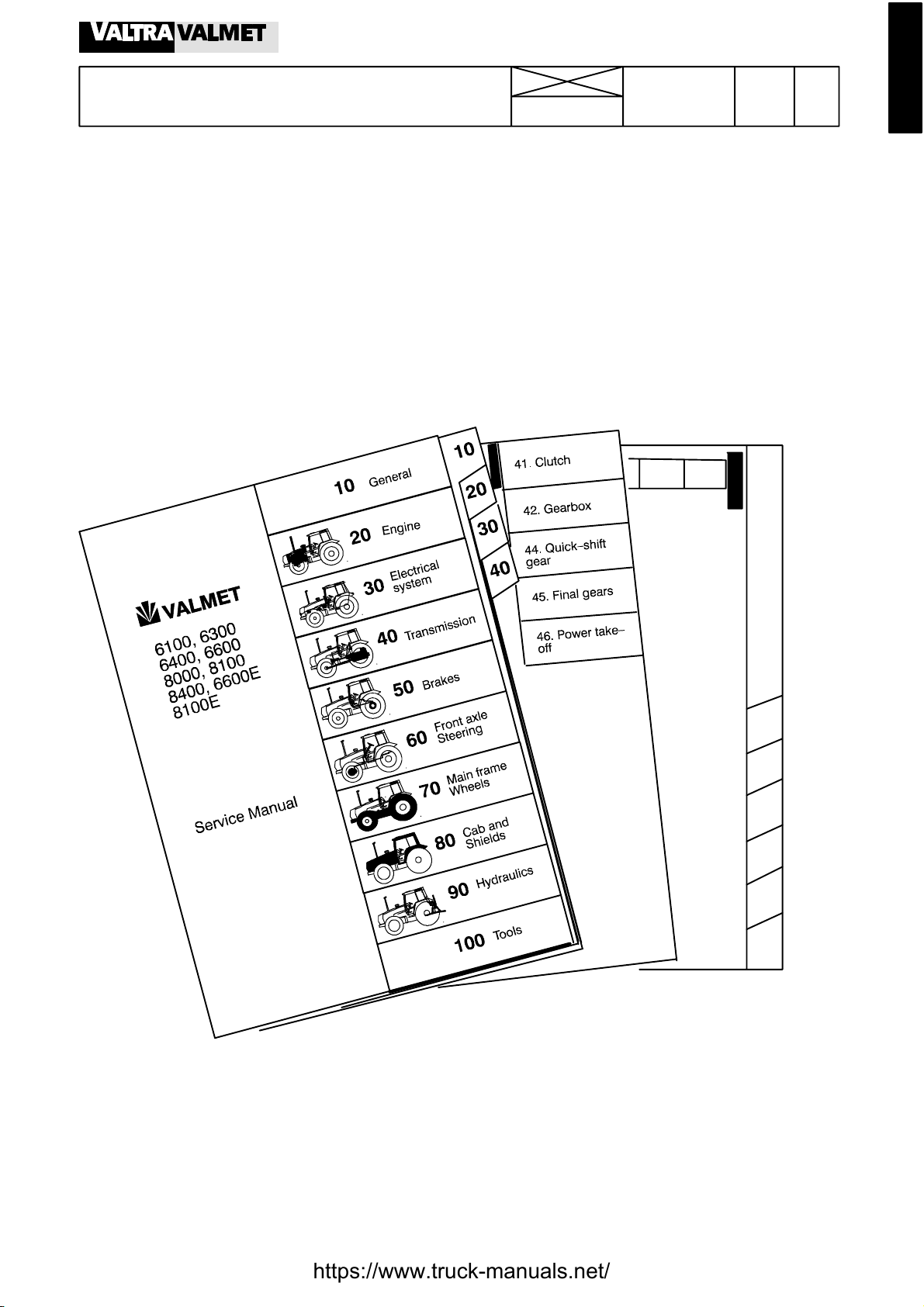
1. Division into groups
The manual is divided into groups (10 ---100) which are based on the make ---up of the tractor.The groups are listed on the first index
leaf.
Example. 10. General
20. Engine, fuel and cooling systems
30. Electrical system
40. Power transmission
a.s.o.
The number designation for each group is given in the top left box of the respective pages (and the first figure in the code designation)
Code
410 1
Page
50
60
70
80
90
100
2. Division into components or sub ---groups
Each group is further divided into components or sub---groups. The number and the name of each component is given in the top
left box on each page (and comprise the two first figures in the code designation).
Example. 41. Clutch
42. Gearbox
44. Quick ---shift gear
45. Final drives etc.
7
Page 11
Model Code Page
11. Layout
8. 11. 1990
6000--8750 110 2
3. Code designation
Three---digit code designations are used to distinguish the different document groups for the respective components. The same
code is also used in the Time List as a reference to the text in this Manual. The code designation numbers appear both in the box at
thetopofthepageandalsointheheadings.
Example: Code 410:
--- Group: Power transmission (4)
--- Component: Clutch (41)
--- Document group: General (410)
4. Page numbers
The instructions for all components are numbered in consecutive order in the right---hand box at the top of the page. The page
numbers begin with page 1 for each component.
Page
41. Clutch
8. 11. 1990
15. 5. 1993
Model Code
6100--- 8400 410 1
5. D a te
At the top of each page there are two boxes for dates. In the case of a revised issue, the date of the earlier issue is printed in the
crossed---overboxandthedateofthecurrentissueisprintedinthe”real”datebox.
6. Mo del
At the top of each page the tractor model for which the page is valid is indicated.
7. Additions and amendments of the service manual
New and up -- -dated pages will be continually added to the service manual. The new pages should be inserted as indicated by the
code: the first digit (also the first digit on the index leaf) indicated the group:
--- the two first digits indicate the component or sub --- group
--- the third digit indicates the document group for the respective components
--- the page number indicates the definite position of the page within the service manual
If there are two pages with the same code and page number the page with the later date in the date box (and the old date in the
crossed--- over box) is valid (or the current page).
N.B. Fitting instructions for extra equipment are inserted into the service manual at the end of group concerned (E.g. code 39 is
inserted at the end of group 30).
8
Page 12

11. Layout
Code designation in the Service Manual
10. General
110 Layout
120 Repairs
130 Maintenance
20 Engine
21. Engine
210 Technical data, tools, description
211 Cylinder block and flywheel housing
212 Cylinder head and valve mechanism
213 Crank mechanism
214 Timing gears
215 Lubrication system and oil sump
216 Induction and exhaust system, turbocharger
219 Removing and fitting engine
22. Fuel system
220 Technical data, tools, description
222 Fuel feed pump and fuel filters
223 Injection pump and injectors
8. 11. 1990
1. 4. 1997
Model Code Page
6000--8750 110 3
23. Cooling system
230 Technical data, tools, description
231 Thermostat and coolant pump
30. Electrical system
310 Specifications, wiring diagrams
311 Autocontrol II
312 Autocontrol 2.1
313 Sigma ---power
320 AC power lift
321 ACD power lift
330 Agrodata
331 AD---instrument
340 Autocontrol ---III
350 Autocontrol IV
360 CareT el
40. Power transmission
41. Clutch
410 Technical data, tools, description
411 Clutch assembly and pedal rods
412 Hydraulic coupling
42. Gearbox
420 Technical data, tools, description
421 Selector forks
422 Gear shift levers
423 Shafts and gear wheels
424 Differential
44. Quick--- shift gear, DPS, reverse shuttle, 4WD clutch
440A Quick ---shift gear , technical data, tools, description
440B Reverse shuttle, technical data, tools, description
440C 4WD clutch, technical data, tools, description
441 Quick--- shift gear, repair instructions
442 Reverse shuttle, repair instructions
443 4WD clutch, repair instructions
444 DPS, repair instructions
45. Final drives
450 Technical data, tools, description
451 Final drives, repair instructions
4 6 P o w e r t a k e --- o f f
460 Technical data, tools, description
461 Power take---off, repair instructions
463 Front PTO, repair instructions
9
Page 13
11. Layout
50. Brakes
510 Technical data, description
511. Service brakes
520 Parking brake
60. Steering system and front axle
61. Steering system
610 Technical data, tools, description
611 Steering valve
612 Priority valve
613 Steering cylinder
614 Adjustment
64. Powered front axle
640 Technical data, tools, description
641 Front axle housing and front axle suspension
643 Hubs
644 Differential
645 Industrial front axle
70 Frame and wheels
710 Tractor frame
720 T yres and wheel discs
8. 11. 1990
1. 4. 1997
Model Code Page
6000--8750 110 4
80 Cab and shields
810 Cab
820 Shields
830 Air conditioner
90 Hydraulics
910 Technical data, tools, description
911 Pump and pipes
912 Working hydraulics
913 Three---point linkage, towing hook
920 AC power lift
100. Special tools
101 Special tools (ETV)
102 Locally manufactured tools
Note! Separate fitting instructions for the optional equipments are inserted into the Service Manual. These instructions are positioned to the end of each main group. E.g. code 39 are placed to the end of group 30.
10
Page 14
Model Code Page
12. Repairs
8. 11. 1990
6000--8750 120 1
General instructions for repairs
Outer oil seals
The Service Manual contains instructions for changing all outer oil seals, (e.g. oil seals on the PTO shaft end, on the output shaft
to the front wheel drive and on the pinion shaft on the powered front axle, and so on).
Sealing compound and glue
If sealing compounds or glue are required for the repair work, the instructions will specify a sealing compound or glue which is
readily available through specialist dealers. Some seals should be greased before fitting and the space between the lips of the
seal should be filled with universal grease. If the seal is to be pushed over splines or sharp edges the seal should be protected
with for example a thin plastic foil.
Tightening torques and setting values
All necessary tightening torques and setting values for each repair operation are given at the beginning of each repair section
under the heading Technical Data. The most important values can also be found in the repair instructions.
Table 1 later gives the tightening torques in order of dimension, quality and surface treatment. The values given in the table should
be used if the tightening torque is not given in the repair instructions.
Safety
Always bear safety in mind when repairing or servicing the tractor. Use tools and lifting devices in the correct way . When you
are removing tractor components or splitting the tractor,every tractor part must be supported in such a way,that no risk of accident
exists. Avoid working under the supported tractor part if it is not absolutely necessary. When supporting the tractor the centre of
gravity of the frame part must always be checked. For instance the wedges must always be fitted between front axle and engine
to prevent axle oscillation when splitting the front frame of the tractor.
Trouble ---shooting
The following procedure, combined with the information contained in the workshop manual will be helpful in tracing faults accurately. It consists of following a number of logical steps to locate and correct the problem:
a) Determine the problem
b) List possible causes
c) Differentiate the causes
d) Conduct checks in logical order to determine the exact cause
e) Consider approximate remaining service life against cost of parts and labour..
f) Make any necessary repairs.
g) Recheck the parts and functions for correct operation
11
Page 15
12. Repairs
8. 11. 1990
Model Code Page
6000--8750 120 2
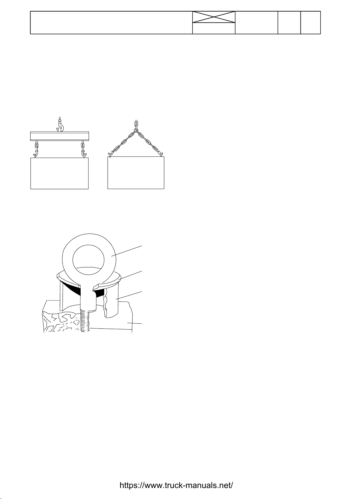
Handling of heavy components
Unless otherwise specified, all removals should be accomplished using adjustable lifting equipment. All supporting
slings must be parallel to each other and as near vertical as
possible in relation to the object being lifted. However, where
slings are of a far greater capacity than the weight of the load
to be fitted, a triangular lifting arrangement may be used.
Oikein
Rätt
Right
Richtig
Giusto
When removing a component at an angle, remember that the
capacity of an eyebolt is reduced when the angle between the
supporting members and the object becomes less than 90˚.
Correct
Teisingai
Väärin
Fel
Wrong
Falsch
Sbagliato
Mauvais
Neteisingai
B
Cleanliness
To ensure longlife of a machine, it is important to keep dirt and
foreign material out of its vital working components. Precautions must be taken to safeguard against this. Enclosed compartments, seals and filters have been provided to keep the
supply of air, fuel and lubricant clean. These protective devices must not be removed.
Whenever hydraulic, fuel, lubricating oil or lines are disconnected, clean the point of disconnectionand the surrounding
area. As soon as a line has been disconnected, cap, plug or
tape the line or opening to prevent the ingress of foreign material.
The samecleaning and covering precautionsshould be taken
when access covers or inspection plates are removed.
Clean and inspect all parts. Make sure that all passages and
holes are clear. Cover all parts to keep them clean. Make sure
parts are clean when they are reassembled. Leave new parts
in their wrapping until they are actuallyneeded for reassembly
Assembly
When reassembling a machine, complete each step in sequence. never partially assemble one part then start to assemble another. Make all recommended adjustments. Al ways check the job on completion to ensure that nothing has
been overlooked. Recheck the various adjustments before
putting the machine back into service.
C
D
A
Forged eyebolt support
A. Load
B. Lifting shackle
C. Shackle retaining plate ( 3 mm thick)
D. Sleeve
When necessary the forged eyebolt can be supported in the
way shown in figure above. Sleeve D may or may not be
welded to plate.
Warning! If a part resistsremoval, check that all nuts andbolts
have been removed and that there is no interference from adjacent parts.
Note! Before fitting new parts, remove rust preventative compound from all machined surfaces (usually ”peel --- off substances).
Lubrication
Where applicable, fill the compartments of repaired or renewed components with the quantity, type and grade of clean
lubricantrecommended in the routine maintenance sectionof
the Operator’s Manual.
Shims
When shims are removed, tie them together and identify their
location. Keep shims clean and take care not to bend them
before refitting them.
Gaskets
Make sure that the holes in gaskets line up with lubricating oil
passages in the mating parts. If gaskets have to be made, use
material of the correct type and thickness. Make sure that
holes are punched in the right places.
Incorrectly punched gaskets can cause serious damage.
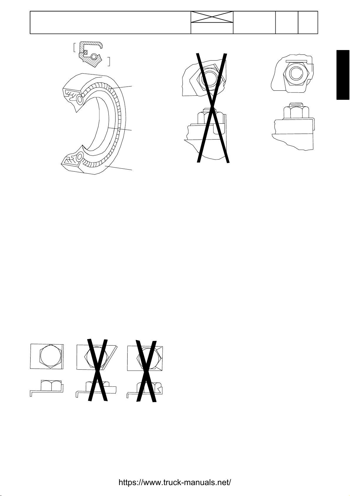
Lip type rubber seals
Lubricate the lips of lip---type rubber seals with oil before fitment. Do not use grease on seals, except for grease seals.
12
Page 16
12. Repairs
4
Model Code Page
8. 11. 1990
6000--8750 120 3
5
3
2
1
The main parts of lip --- type seal:
1. Case
2. Sealing element
3. Ring spring
The figure above shows the constructionof a simple lip ---type
seal. The cross section shows the heel (4) and the toe (5),
used to identify the sides of a single element seal. With a few
exceptions, the toe of a single - --lip is located on the lubricant
side. Some seals have a second auxiliary lip which has no
spring.
Cables and wires
When removing or disconnecting a group of cables or wires,
label each one to ensure correct refitment.
Locking devices
Correct and incorrect method of fitting and bending locking
tabs.
Slackening of nuts and bolts is prevented by mechanical
means such as lockwashers, tab washers and cotter pins, or
by Loctite---type locking agents.
Flat retainers must be installed properly to be effective. Bend
one end of the retainer against the edge of the part. Bend the
other end against one of the nut or bolt head.Always fit new
retainers in compartments which house moving parts. When
fitting lockwashers on aluminium housings, place a flat
washer between the lockwasher and the housing.
Note!
1) Never fit a lockwasher (Grower, fan, spring, etc.)under a nut
or bolt to which a specified torque has to be applied.
2) Always thoroughly degrease components before applying
Loctitetypelockingagents.
Bushes and press fits
Do not fit bushes with a hammer alone. Use a suitable fitting
tool and a hammer or, better still, a press if possible..
Correct and incorrect use of retainers
When using a press, ensure that pressure is applied directly
in line with the bore. If the ring has an oil hole, take care to align
it with the oil hole in the mating part. When press fitting a part
into anotherpart, lubricate the mating surfaces. Tapered parts
should be assembled dry. Before assembly, check that the
tapers are dry and free from burrs.
Fitting bolts in blind holes
Use bolts of the correct length. A bolt which is too long may
”bottom” before the head comes into contact with the part it
is to hold: this will cause damage to the threads. If a bolt is too
short, there may not be enough threads engaged to hold the
part securely.
13
Page 17
Model Code Page
12. Repairs
8. 11. 1990
6000--8750 120 4
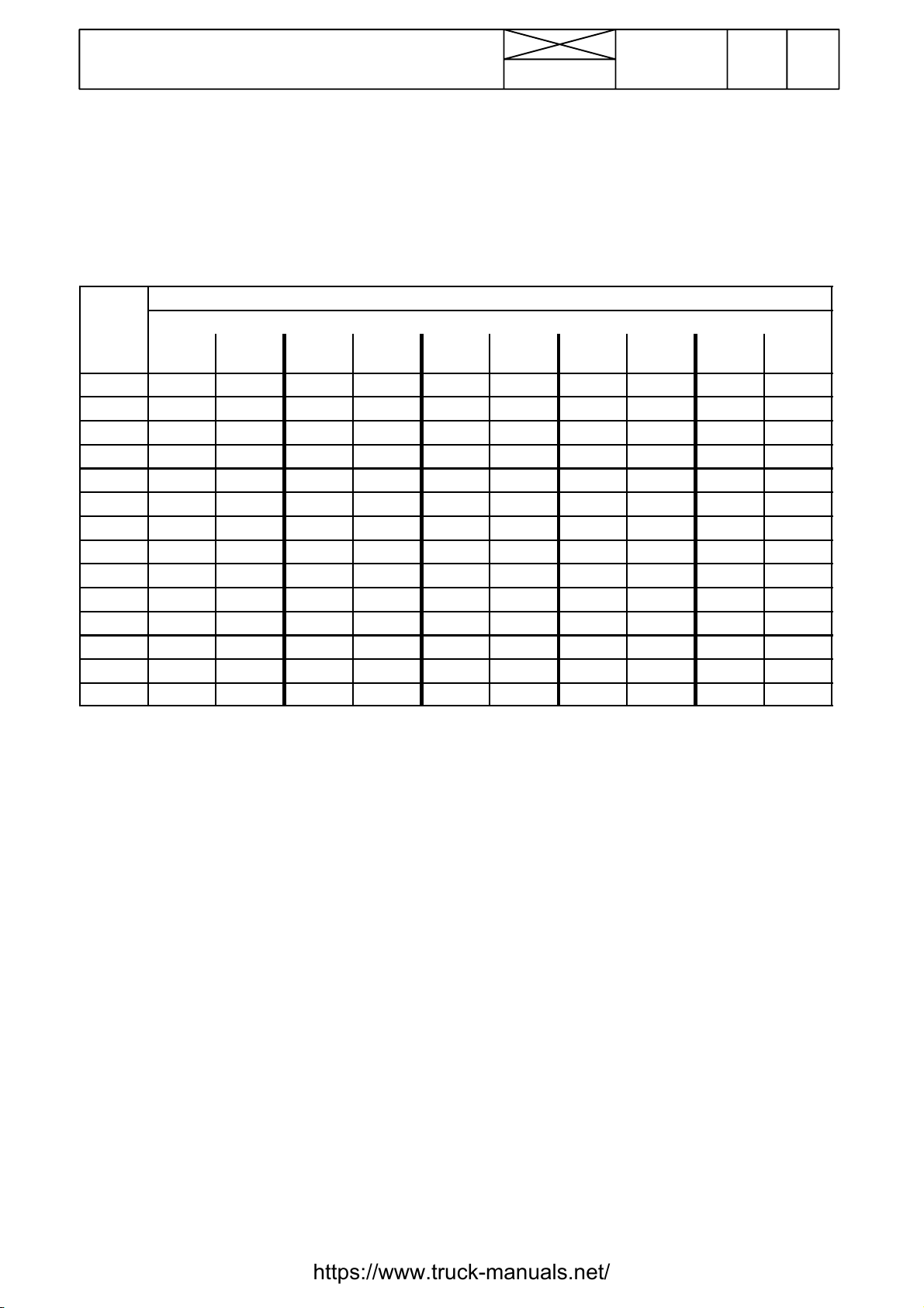
Tab l e
Ta b l e 1 . Tightening torques, metric standard thread (ISO)
Tightening torques Nm1)
Dim. Quality, surface treatment, material and so on
8.8
lubr.
M4 --- --- --- --- --M5 6,4 0,6 5,7 0,5 --- 9 1 11 1
M6 11 1 10 1 12 1,2 15 1,5 18 2
M8 25 2 23 2 30 3 35 4 45 5
M10 50 5 45 5 60 5 70 7 90 10
M12 90 10 80 8 100 10 125 10 151 15
M14 140 15 125 10 160 15 200 20 240 20
M16 220 20 195 20 250 25 300 30 370 40
M18 300 30 270 30 350 35 430 40 510 50
M20 430 40 380 40 480 50 600 60 720 70
M22 570 60 500 50 650 65 800 80 970 100
M24 740 70 660 70 830 80 1030 100 1250 120
M27 1100 100 950 100 1200 120 1500 150 1800 180
M30 1500 150 1300 130 1600 160 2040 200 2500 250
tol.±
8.8
Zne
2
) tol±
8.8
3
Znk
) tol. ±
10.9
lubr.
tol. ±
12.9
lubr
tol. ±
1
) 1 Nm=0,102 kpm
2
) Zne=zinc electroplating
3
)Znk=hotgalvanized
If the bolts differs from the standard range the values in the
table must not be used.
14
Page 18
12. Repairs
8. 11. 1990
Conversion table for common units
Quantities and units Conversion factors
Overall and detail dimensions millimetres (mm) 100 mm=3,94 inches
1 inch=25,4 mm
Short distances e.g. turning circles metres (m) 1 m=3,28 ft
1 ft=0,305 m
Travel distances kilometres 1 km=0,62 mile
1 mile=1,61 km
Tractor weights, axle loadings kilograms (kg) 1 kg=2,2 lbs
1 lb=0,454 kg
Travel speed kilometres per h (km/h) 1 km/h=0,62 mph
1mph=1,61km/h
Drawbar pull kilonewtons (kN) 1 kN=224,8 lbs
1 lb=4,448 N
Power (identified by such terms as crankshaft power, 1 kW=1,34 hp
pto power, belt power, drawbar power, indicating 1 hp=0,746 kW
the point at which the measurement was taken)
kilowatts (kW)
Model Code Page
6000--8750 120 5
Engine torque newton metres (Nm) 1 Nm=0,74 ft lb
1 ft lb=1,356 Nm
Fuel consumption by weight (kilograms per hr, kg/h) 1 kg/h=2,2 lb/hr
(by volume) litres per hr (l/h) 1 lb=0,454 kg
1l/h=0,22gal/hr
1gal=4,54l
Fuel economy (specific fuel consumption) 304 g/kWh=0,5 lb/hp hr
grams per kilowatt hr (g/kWh)
Engine displacement litres (l) 1 l=61,02 m cu in
100 cu in=1,639 l
Hydraulic pump 1 MPa=145 psi
pressure---mecapascal (MPa) 1000 psi=6,9 MPa
delivery ---millimetres per sec (ml/s) 100 ml/s=1,32 gpm
1 gpm=75,77 ml/s
Tyre
pressure---kilopascal (kPa) 100 kPa=14,5 psi
1psi=6,9kPa
Area acres---hectare To convert multiply by
0,404686
Volume bushel---litre To convert multiply by
39,3687
Quantity pound per acre---kilogram per hectare Multiply by 1,12085
Volume Multiply by
superficial foot ---cubic metre 0,002360
15
Page 19

16
Page 20
13. Maintenance
Maintenance Valmet 6000---8750
N.B. Detailed maintenance instructions, see Operator’s Man-
ual.
1. 1. 1994
15. 5. 1996
Model Code Page
6000--8750 130 1
Greasing lubricating points fitted with
grease nipples
General
Correct maintenance at the right time is a basic condition for
reliable operation of the tractor. Maintenance costs are small
compared with any repair costs resulting from lack of maintenance. The most important measures are those which you
carry out yourself and which include lubrication and various
checks and adjustments.
The serviceintervals shown apply for normal operating conditions but in more severe conditions servicing should be carried out more frequently.
General instructions concerning oil
checks and oil filling
--- Alwaysstoptheenginebeforestartingwork
--- Apply the parking brake to ensure the tractor cannot
move. If the ground is uneven the wheels should be
scotched
--- W ashdown the tractor first so that the work can be done
more easily and quickly.
--- Always observe the utmost cleanliness in all maintenance work. Thoroughly wipe off filler caps and plugs as well
as surrounding parts of the tractor before filling up with fuel
or oil.
--- Inspect the oil and filters when changing. Large
amounts of dirt (e.g. heavily clogged filters) can point to a
fault which could cause extensive and costly repairs if not
corrected in time.
---When carrying out checks the tractor should stand on level
ground.
--- Levels should be checked in the morning when the oil
is cold and has had time torun down to the bottom of the unit
concerned.
--- When changing the oil, bear in mind that the oil can be
very hot when it drains from the tractor. Waste oil and oil
filtersshouldbehandledcarefullyanddisposedofproperly
--- After completion of the service work always replace all
safety covers etc.
--- Always clean the grease nipples before applying the
grease gun.
--- Apply grease through the nipples until clean grease
oozes out (unless otherwise instructed).
--- Wipe away superfluous grease which has been
pressed out at the lubricating point.
--- Preferably carry out lubrication with bearing points and
joints unloaded and with the bearings in different positions.
Lubrication and maintenance schedule
All intervals are countedfrom zerohours on the hour recorder.
For example, 1000 hours service is carried out every 1000
(yearly), 2000 hours (every other year) etc. even if the guarantee service has been carried out.
Example: The 1000 hour service contains all items mentioned
under 10 h/Daily, 50 h/once a week, 250 h, 500 h and 1000 h.
17
Page 21

13. Maintenance
Maintenance schedule
18
7
4
15. 5. 1996
1. 4. 1997
Model Code Page
6000--8750 130 2
14
5
11 12 1415
14
15
6
1
2
6
4
5
16 17
Daily/every 10 hours
1. Check engine oil level
2. Check coolant level and radiator fins
3. Check for leakage
Weekly/every 50 hours
4. Grease three ---point linkage and towing hook
5. Grease brake mechanism (EP grease)
6. Grease front axle brackets (also nipples on steering system
andonnon---poweredfrontaxle)
7. Check oil level in transmission and hydraulics
8. Clean air filter cyclone (tractors with a horizontally fitted air
filter and an ejector pipe; clean suction housing hole plate)
9. Check fan belt tightness
10.Check water trap (on 6--- cylinder engines. On other mo-
dels on the other side. On models 8200, 8400 and
8050---8750 also under both fuel filters)
11.Check electrolyte level in battery
8910
6
15
14
66
6084--- 67
Every 250 hours
12. Clean engine air filter
13. Grease door and window hinges and locks
14. Change engine oil and filter
15. Grease front axle joints (powered axle)
16. Change pressure filters. First change at 100 hours warranty service,then at 250 hours and after that at 500 hours
and then at intervals of 500 running hours.
17. Check brake fluid level (and clutch fluid level,
668103---)
18. Clean cab ventilation air filter
19. Check wheel nuts and bolts and tyre pressures
18
Page 22

13. Maintenance
1. 4. 1997
1. 11. 1998
Model Code Page
6000--8750 130 3
25
27 30 25 34 22 27 29 31 36 28 33
26
24
39
35
36 32
30 25 38 21 23 37 20 41 33
Every 500 hours
20. Clean water trap (fuel system) (on 6 ---cylinder engines.
On the other models on the other side. On models
8200, 8400 and 8050---8750 also under the fuel filters).
Does not concern 6200 and 8000R tractors.
21. Check brake pedal free travel
22. Check clutch pedal free travel, ---668102.
23. Change pressure filters (transmission and hydraulics)
24. Check oil level in front axle differential and hubs
24a. Calibrate first time gaspedal on HiTech models. Later at
intervals of 1000 running hours.
Every 1000 hours/yearly
25. Change oil in transmission/hydraulic s and clean suc-
tion strainer
26. Change oil in front axle differential and hubs
27. Change cab ventilation air filter and wash cab recirculation filter, if fitted.
28. Change fuel filters. 6200, 8000R: change also the water
trap filter
29. Change safety filter (in engine air filter)
30. Greasereardriveaxlebearings
31. Grease flywheel ring gear
32. Check, grease and adjust front wheel bearings on
non---powered front axle
33. Check/adjust front wheel toe---in
34. Clean fuel tank
35. Adjust valves
35a Calibrate gas pedal on HiTech models
24
42 40 43 33 32
26
6084--- 68
Every 2000 hours/every other year
36. Change engine coolant
37. Change brake fluid (and clutch fluid, 668103--- )
38. Change transmission housing breather
39. Check and clean injectors
40. Check alternator
41. Check starter motor
Every 4000 hours
42. Check function of turbocharger at authorized workshop (if
fitted)
43. Change engine rubber vibration damber on 6---cyl.
engines (not 8200 and 8450 ---8750)
19
Page 23

Model Code Page
C
G
10W/30+30
C
20CCH---4
Coolingsystem
:
ater+ant
e
ezeag
ent(stand
ardiA
S
water+ant
i
freezeagent(standardiASTM
)
6000--8950 130 4
13. Maintenance
1. 8. 2000
1. 9. 2002
Recommended fuel and lubricants (all capacities are incl. of filters)
Part of machine S A E --- g r a d e AP I --- g r a d e Capacity (litres)
Engine:
--- 6100 (3 ---cyl.)
--- 6000, 6200 ---6650Hi, 6800 ---6850Hi (4 ---cyl.)
-- 6900, 8000, 8100, 8200, 8400, 8050--8950Hi (6--cyl.)
Hydraulics/transmission HT 60: ---30˚C...+30˚C
Powered front axle:
--- differential, Dana / ind. Carraro
--- hubs, Dana 80W/90 GL---5 (LS) 2x1
--- hubs, ind. front axle Dana+Carraro 2x1,5
Fuel tank:
--- 6000--- 8000 Hi Trol, 6250Hi---6650Hi HiTrol
--- o th e r mo d el s
--- extra fuel reservoir, metallic / plastic +82 / +121
Cooling system:
--- 6100 (with larger radiator) 13,5 (17,5)
--- 6000, 6200 ---6600 (with openable front grille) 15,5 (17)
--- 6250 Hi ---6650 Hi 17
--- 6800 / 6850 Hi
--- 8000- --8400 (with openable front grille)
--- 8200, 8400, 8050, 8150 with expansion tank
--- 8050 Hi and 8150 Hi 28
--- 8450, 8550 / 8450 Hi, 8550 Hi 25 / 27
--- 8750 / 8950Hi 31 / 31
Brake fluid reservoir/Clutch fluid resesvoir brake fluid SAE J1703 0,3 / 0,2
Window washer reservoir washer fluid 3
Oils in front PTO units see page 463/9.
*) Tractor frame numbers, see page 450/6.
**) Tractor frame numbers, see page 450/8.
15W40 +40˚C... ---10˚C
HT 100: ---10˚C...+40˚C
diesel fuel
w
D3306---86a tai BS 6580:1985)
i---fr
---
˚
˚
...---
˚
---
˚
--- 4
CH --- 4
GL---4
(G 2 --- 9 8)
TM
10
13
19
34 (43 max/HiTech, 8050---,
J02316---: 45 max)
(extra max 50/HiTech,
8050---, J02316---: extra max
6200---8950 *): min 45, max
55, extra max 65.
8950Hi **): min 45, max 55,
extra max. 65.
8/6
158
165
22 / 22
24 (25)
28 (8400, model 2001:
30)
53).
Oil qual ity and capacity in fluid couplings (Hi --- Trol)
Vo i t h T D --- V A coupling used up to serial no 658205 and V o i t h T D --- F V A 1 from serial no 666066. Engine oil SAE 10W/30 year
around or automatic transmission fluid ATF which meets standards: GM type A Suffix A, GM Dexron II (e.g. Neste ATF --- X):
--- 6000, 6100 --- 7,20 litres
--- 6200, 6300 7,4 litres 6200: 7,35 litres. 6300: 7,45 litres. 6250Hi: 7,40 litres. 6350Hi: 7,80 litres.
--- 6400 7,6 litres 7,85 litres. 6550Hi: 7,90 litres.
--- 6600 7,8 litres 7,90 litres. 6650Hi: 8,00 liter
--- 6800, 8000R, 8000 6800: 8,40 litres. 6900, 8000: 8,00 litres. 6850Hi: 8,00 litres.
Tra ns f l u i d ---coupling with effect from tractor serial no 658206 up to tractor serial no 666065. Engine oil SAE 10W/30 year around
or automatic transmission fluid ATF which meets standards: GM type A Suffix A, GM Dexron II (e.g. Neste ATF ---X):
--- 6100 5,2 l 6,4 l
--- 6300 5,4 l 6,6 l
--- 6400 5,6 l 6,8 l
--- 6600, 8000 5,8 l 7,0 l
*
) Check the manufacturing date of the coupling. If it is 1292 or later, use larger filling quantities.
---658205 666066 ---
658206--- 659409 ---666065
659408
*
)
4
Page 24

20. Engine
21. Engine
22. Fuel system
23. Cooling system
21
Page 25

22
Page 26

Model Code Page
21. Engine
15. 6. 1992
1. 9. 1992
Contents
General ( Op. no. 210):
Specifications 3...................................................................
Special tools 10....................................................................
Engine, description 12..............................................................
Repair instructions
Cylinder block and flywheel housing (Op. no. 211):
1. Cylinder block and cylinder liners:
A. Measuring cylinder liner wear 1...................................................
B. Removing cylinder liners 1........................................................
C. Checking cylinder block 1........................................................
D. Changing camshaft bushing 1....................................................
E. Oversize bushings for camshaft 2.................................................
F. Fitting plug at rear end of camshaft 3...............................................
G. Fitting pipe for oil dipstick 4......................................................
H. Fitting cylinder liners 4...........................................................
6000--8750 210 1
2. Flywheel housing:
A. Fitting flywheel housing 6........................................................
B. Changing crankshaft rear oil seal 6................................................
C. Changing flywheel starter gear 7..................................................
D. Fitting flywheel 7................................................................
Cylinder head and valve mechanism (Op. no. 212):
1. Cylinder head:
A. Removing cylinder head 1........................................................
B. R emoving valves 1..............................................................
C. Checking cylinder head 1........................................................
D. Changing valve guides 2.........................................................
E. Machining valve seat 2...........................................................
F. Changing valve seat inserts 3.....................................................
G. Grinding valves 3...............................................................
H. Fitting valves 3.................................................................
I. Fitting cylinder head 4............................................................
2.Valve mechanism:
A. Reconditioning rocker arm mechanism 5...........................................
B. Changing camshaft/camshaft gear 5...............................................
C. Adjusting valve clearance 6.......................................................
Crank mechanism (Op. no. 213):
1. Crankshaft:
A. Removing crankshaft 1..........................................................
B. Checking crankshaft 1...........................................................
C. Changing crankshaft gears 1.....................................................
D. Changing crankshaft ring gear (420---engines) 2.....................................
E. Fitting crankshaft 2..............................................................
2. Connecting rods and pistons:
A. Removing piston together with connecting rod 3.....................................
B. Changing connecting rod bearings 3...............................................
C. Checking connecting rod 3.......................................................
23
Page 27

21. Engine
15. 6. 1992
1. 9. 1992
D. Connecting rods, weight classes 4.................................................
E. Changing piston rings 5..........................................................
F. Ch e ck i ng p i st o n 6...............................................................
G. Fitting piston pin 6..............................................................
H. Fitting piston together with connecting rod 6........................................
3. Balancer unit, 420 ---engines:
A. Removing and dismantling balancer unit 7..........................................
B. Reconditioning balancer unit 7....................................................
C. Fitting balancer unit 8............................................................
Model Code Page
6000--8750 210 2
Engine timing gears (Op. no. 214)
A. Removing timing gear casing 1...................................................
B. Reconditioning idler gear 1.......................................................
C. Fitting timing gear casing 2.......................................................
Lubrication system and o il sump (Op. no. 215):
A. Reconditioning oil relief valve for lubrication oil pressure 1.............................
B. Removing and dismantling lubricating oil pump 1....................................
C. Assembling and fitting lubricating oil pump 2.......................................
D. Fitting oil sump gasket 2.........................................................
E. Lubricating oil quality requirements 3..............................................
Inlet and exhaust system, turbocharger (Op. no. 216):
A. Checking air filter 1..............................................................
B. Checking inlet and exhaust system 1...............................................
C. Checking turbocharger 1.........................................................
D. Reconditioning turbocharger 3....................................................
E. Fitting turbocharger 5............................................................
Working orders (Op. no. 219) 1................................................
24
Page 28

21. Engine
1. 8. 2000
1. 9. 2002
Model Code Page
6000--6800 210 3
Specifications
Engine designations
1. Basic markings: 320, 420, 620 and 634. The first digit indicates the number of cylinders and the two last digits the stroke
(---20=120 mm, ---34=134 mm).
2. Letters after the basic markings:
--- D=diesel engine
--- S=turbocharger (Schwitzer)
--- W=by--pass turbocharger, Delta turbo
--- B=Bosch P in---line pump
Note! R 24 , E 77 a n d EPA --- h o mo l og a ti o ns h a s b e e n ma d e f o r E --- e ng i n es .
Tractor 6000 6100 6200 6200 6250 Hi 6300 6300
Designation 420D 320 DS 420DSRE 420DSRE 420DSRE 420 DS 420DS
Turbocharger no yes yes yes yes yes yes
Noofcylinders434444 4
Displacement (litres) 4,4 3,3 4,4 4,4 4,4 4,4 4,4
Cyl. bore (mm) 108 108 108 108 108 108 108
Stroke (mm) 120 120 120 120 120 120 120
Compr. ratio 16,5:1 16,5:1 16,5:1 16,5:1 16,5:1 16,5:1 16,5:1
Output (kW/r/min DIN) 55/2300 58/2300 59/2225 59/2200 59/2200 62,5/2225 66/2200
Torque (Nm/r/min DIN) 290/1450 310/1550 320/1400 360/1400 360/1400 330/1550 360/1400
Momentrise%2728,527414123 25
Low idling (r/min) 750 800 750 750 850 750 750
Compr. press
Max. no--load revs (r/min) 2500 2500 2425 2400 2400 2425 2400
1
) (bar) 24 24 24 24 24 24 24
(Schwitzer S1BG or S2BG)
(---K41123) (K41124--- ) (K41309 ---
--- R=distributor pump (Stanadyne)
--- I=intercooler
--- E=low emission engines (E---engines)
--- C=emission tested engines (certificated).
---L23437)
Tractor 6300 6350 Hi 6400 6400 6400 6400
(L23438---) (J17109---) (K41106---) (L23506---)
(Delta) (Delta)
Designation 420DSRE 420DSRE 420 DS 420 DW 420DW 420DWRE
Turbocharger yes yes yes yes yes yes
Noofcylinders444444
Displacement (litres) 4,4 4,4 4,4 4,4 4,4 4,4
Cyl. bore (mm) 108 108 108 108 108 108
Stroke (mm) 120 120 120 120 120 120
Compr. ratio 16,5:1 16,5:1 16,5:1 16,5:1 16,5:1 16,5:1
Output (kW/r/min DIN) 66/2200 66/2200 70/2225 70/2225 73,5/2200 73,5/2200
Torque (Nm/r/min DIN) 400/1400 400/1400 365/1550 390/1550 415/1400 430/1400
Momentrise%393922313035
Low idling (r/min) 750 850 750 750 750 750
Compr. press
Max. no--load revs (r/min) 2400 2400 2425 2425 2400 2400
Tractor 6550 Hi 6600 6600E 6650 Hi 6750Hi*) 6800 6800E
Designation 420DWRE 420 DS 420 DS 420DWRE 420DWRIE 420 DWI 420DWI
Turbocharger yes yes yes yes yes (+interc..) yes (+interc..) yes (+interc..)
Noofcylinders444444 4
Displacement (litres) 4,4 4,4 4,4 4,4 4.4 4,4 4,4
Cyl. bore (mm) 108 108 108 108 108 108 108
Stroke (mm) 120 120 120 120 120 120 120
Compr. ratio 16,5:1 16,5:1 16,5:1 16,5:1 16,5:1 16,5:1 16,5:1
Output (kW/r/min DIN) 73,5/2200 77/2225 77/2225 81/2200 77/1800 85/2225 85/2225
Torque (Nm/r/min DIN) 430/1400 405/1550 405/1550 460/1400 530/1150 440/1550 440/1550
Momentrise%352222312921 21
Low idling (r/min) 850 850 850 850 800 850 850
Compr. press
Max. no--load revs (r/min) 2400 2425 2425 2400 2000 2425 2425
1
) (bar) 24 24 24 24 24 24
1
) (bar) 24 24 24 24 24 24 24
1
) Minimum value at operating temperature and starting revs. Max permitted difference between cylinders 3,0 bar.
*)Lowrevsengine.
E = AC- --4, Control system for tractor.
Hi =HiTech.
5
Page 29

21. Engine
1. 8. 2000
1. 9. 2002
Model Code Page
6800--8400 210 3A
Specifications
Tractor 6800 6850 Hi 6900 8000 8050 8050
(L23517---) (---L23317) (L23318---)
Designation 420 DWRIE 420 DWRIE 620 DRE 620 D 620 DSR 620DSRE
Turbocharger yes (+interc..) yes (+interc..) no no yes yes
Noofcylinders446666
Displacement (litres) 4,4 4,4 6,6 6,6 6,6 6,6
Cyl. bore (mm) 108 108 108 108 108 108
Stroke (mm) 120 120 120 120 120 120
Compr. ratio 16,5:1 16,5:1 16,5:1 16,5:1 16,5:1 16,5:1
Output (kW/r/min DIN) 88/2200 88/2200 75/2225 73,5/2225 81/2200 81/2200
Torque (Nm/r/min DIN) 490/1400 490/1400 390/1400 380/1550 490/1300 490/1400
Momentrise%282821203921
Low idling (r/min) 850 850 750 750 750 850
Compr. press
Max. no--load revs (r/min) 2400 2400 2425 2425 2400 2425
Tractor 8050 Hi 8100 8100E 8150 8150E 8150 8150 Hi
Designation 620DSRE 620 D 620 D 620 DSR 620 DSR 620DSRE 620DSRE
Turbocharger yesnonoyesyesyesyes
Noofcylinders6666666
Displacement (litres) 6,6 6,6 6,6 6,6 6,6 6,6 6,6
Cyl. bore (mm) 108 108 108 108 108 108 108
Stroke (mm) 120 120 120 120 120 120 120
Compr. ratio 16,5:1 16,5:1 16,5:1 16,5:1 16,5:1 16,5:1 16,5:1
Output (kW/r/min DIN) 81/2200 88/2225 88/2225 92/2200 92/2200 92/2200 92/2200
Torque (Nm/r/min DIN) 490/1400 455/1550 455/1550 540/1300 540/1300 540/1400 540/1400
Momentrise%39212135353535
Low idling (r/min) 750 750 750 750 750 750 750
Compr. press
Max. no--load revs (r/min) 2400 2425 2425 2400 2400 2400 2400
1
) (bar) 24 24 24 24 24 24
(---L24138) (L24139--- )
1
) (bar) 24 24 24 24 24 24 24
Tractor 8200 8200E 8350Hi*) 8400 8400E 8400 8400
(---K34331) (K32135--- (L23130---)
---L33320)
Designation 634 D 634 D 620DSRIE 620 DS 620 DS 620 DS 620 DSIE
Turbocharger no no yes (+interc..) yes yes yes yes (+interc..)
Noofcylinders6666666
Displacement (litres) 7,4 7,4 6,6 6,6 6,6 6,6 6,6
Cyl. bore (mm) 108 108 108 108 108 108 108
Stroke (mm) 134 134 120 120 120 120 120
Compr. ratio 16,5:1 16,5:1 16,5:1 16,5:1 16,5:1 16,5:1 16,5:1
Output (kW/r/min DIN) 95,5/2225 95,5/2225 99/1800 103/2200 103/2200 110/2200 118/2200
Torque (Nm/r/min DIN) 490/1550 490/1550 650/1100 520/1550 520/1550 625/1400 650/1400
Momentrise%20202316163027
Low idling (r/min) 750 750 800 750 750 750 750
Compr. press
Max. no--load revs (r/min) 2425 2425 2000 2400 2400 2400 2400
1
) Minimum value at operating temperature and starting revs. Max permitted difference between cylinders 3,0 bar.
*)Lowrevsengine.
E = AC ---4, Control system for tractor.
Hi =HiTech.
1
) (bar) 24 24 24 24 24 24 24
6
Page 30

21. Engine
1. 8. 2000
1. 9. 2002
Model Code Page
8450--8950 210 3B
Specifications
Tractor 8450 8450E 8450 8450 Hi 8550 8550E 8550
(---L24134) (L24135---) (--- L24115) (L24116--- )
Designation 620 DWR 620 DWR 620 DWRE 620DWRE 634 DSR 634 DSR 634DSRE
Turbocharger yes yes yes yes yes yes yes
Noofcylinders6666666
Displacement (litres) 6,6 6,6 6,6 6,6 7,4 7,4 7,4
Cyl. bore (mm) 108 108 108 108 108 108 108
Stroke (mm) 120 120 120 120 134 134 134
Compr. ratio 16,5:1 16,5:1 16,5:1 16,5:1 16,5:1 16,5:1 16,5:1
Output (kW/r/min DIN) 103/2200 103/2200 103/2200 103/2200 118/2200 118/2200 118/2200
Torque (Nm/r/min DIN) 580/1450 580/1450 615/1400 615/1400 650/1450 650/1450 650/1400
Momentrise%30303838272727
Low idling (r/min) 750 750 750 750 750 750 750
Compr. press
Max. no--load revs (r/min) 2400 2400 2400 2400 2400 2400 2400
Tractor 8550 Hi 8750 8750E 8950 Hi
Designation 634DSRE 634 DS 634 DS 634 DSBIE
Turbocharger yes yes yes yes (+interc..)
No of cylinders 6 6 6 6
Displacement (litres) 7,4 7,4 7,4 7,4
Cyl. bore (mm) 108 108 108 108
Stroke (mm) 134 134 134 134
Compr. ratio 16,5:1 16,5:1 16,5:1 16,5:1
Output (kW/r/min DIN) 118/2200 118/140/2200 118/140/2200 118/147/2200
Torque (Nm/r/min DIN) 650/1400 650/1450 650/1450 650/820/1400
Moment rise % 27 27 27 27/28
Low idling (r/min) 750 750 750 750
Compr. press
Max. no--load revs (r/min) 2400 2400 2400 2400
1
) (bar) 24 24 24 24 24 24 24
(---J32215)
1
) (bar) 24 24 24 24
1
) Minimum value at operating temperature and starting revs. Max permitted difference between cylinders 3,0 bar.
E = AC ---4, Control system for tractor.
Hi =HiTech.
Valves, rockers and tappets
With a valve clearance of 1,0 mm:
--- in l e t v a lv e o pe n s 0˚±2˚ B.T.D.C...............................................................
--- in l e t v a lv e c lo s e s 16˚±2˚ A.B.D.C..............................................................
--- exhaust valve opens 39˚±2˚ B.B.D.C...........................................................
--- exhaust valve closes 1˚±2˚ A.T.D.C...........................................................
Valve clearance cold and hot:
--- in l e t v a lv e 0,35 mm....................................................................
--- exhaust valve 0,35 mm.................................................................
Angle of valve seat in cylinder head:
--- in l e t v a lv e 35˚+20’....................................................................
--- exhaust valve 45˚+20’.................................................................
Width of valve seat in cylinder head:
--- in l e t v a lv e 2,9...3,7 mm....................................................................
--- exhaust valve 1,3...2,3 mm.................................................................
Angle of valve face:
--- in l e t v a lv e 35˚--- 2 0 ’....................................................................
--- exhaust valve 45˚--- 2 0’.................................................................
Outside diameter of valve head:
--- in l e t v a lv e 48 mm....................................................................
--- exhaust valve 41 mm.................................................................
Max valve movement:
--- in l e t v a lv e 10,9 mm....................................................................
--- exhaust valve 12,1 mm.................................................................
Inlet valve stem diameter 8,960...8,975 mm..........................................................
Exhaust valve stem diameter 8,925...8,940 mm......................................................
Inlet valve stem clearance 0,025...0,055 mm.........................................................
--- R ej e c t l i mi t 0,30 mm...................................................................
Exhaust valve stem clearance 0,060...0,090 mm......................................................
--- R ej e c t l i mi t 0,35 mm...................................................................
7
Page 31

21. Engine
1. 1. 1994
1. 8. 1998
Inside diameter of valve guide before fitting 9,000...9,015 mm..........................................
Outside diameter of valve guide 16,028...16,039 mm....................................................
Diameter of valve guide bore in cylinder head 16,000...16,018 mm........................................
Protrusion of valve guide top above cylinder head surface 21 mm..............................
Depth of valve face below cylinder head surface:
--- in l e t v a lv e 0,7±0,05 mm....................................................................
--- exhaust valve 0,6±0,05 mm.................................................................
Valvespringfreelength 69,8mm...........................................................
Spring pressure when spring compressed to a length of:
--- 48 , 6 mm 327±17 N.....................................................................
--- 37 , 4 mm 500±23 N.....................................................................
Rocker arm shaft diameter 19,959...19,980........................................................
Inside diameter of rocker arm bearing bush:
--- (when fitted in position) 19,990...20,010 mm.........................................................
Outside diameter of rocker arm bearing bush 23,035...23,075 mm........................................
Diameter of rocker arm bore 23,000...23,021 mm.......................................................
Max. permissible push rod deflection (when free) 0,4 mm.....................................
Free length of rocker arm spring 80 mm...................................................
Spring pressure when spring compressed to a length 58 mm 80...100 N...........................
Outside diameter of tappet 29,939...29,960 mm........................................................
Diameter of tappet bore in cylinder block 30,000...30,043 mm............................................
Engines from week 34 1996:
Rocker arm shaft diameter 22,970...22,990 mm........................................................
Diameter of rocker arm bore 23,000...23,021 mm.......................................................
Model Code Page
6000--8750 210 4
Camshaft
Diameter of camshaft bearing journal no 1 49,925...49,950 mm...........................................
Diameter of camshaft bearing journals (others that no 1) 49,885...49,910 mm...............................
Diameter of camshaft bearing journals nos 2, 3 and 4 (620/634--- engines) 49,865...49,890 mm................
Inside diameter of camshaft bearing bushes (when fitted in position) 50,010...50,070 mm.....................
Diameter of camshaft bearing bores (others than no 1) 50,000...50,025 mm................................
Camshaft clearance in bearing bush no 1 0,060...0,145 mm............................................
Camshaft clearance in bearing bushes (others than no 1) 0,090...0,140 mm..............................
Camshaft clearance in bearing bushes nos 2, 3 and 4 (620/634 ---engines) 0,110...0,160 mm................
Bearing bush tolerance in block (press fit) 0,025...0,080 mm...........................................
Diameter of bearing bush bore in block 55,620...55,650 mm
Camshaft end play with 0,5 mm gasket between cylinder block and timing gear
housing and between timing gear housing and front cover 0,5...1,0 mm.............................
Cam height (distance between back of cam and tip of cam):
--- inlet valve 41,180...41,430 mm......................
--- exhaust valve 40,080...40,330 mm...................
Cam lift:
--- inlet valve 7,38 mm......................
--- exhaust valve 8,28 mm...................
Camshaft max permissible deflection (total indicator reading) 0,03 mm...........................
Cylinder liners
Protrusion of cylinder liner above cylinder block top face 0,030...0,080 mm...............................
Max. permissible height difference between liners (under same head) 0,02 mm....................
Outer diameter of cylinder liner guide:
--- at upper end of liner 124,475...124,500 mm..............
--- at lower end of liner 122,961...122,986 mm..............
Liner bore 108,000...108,022 mm........................
Height of cylinder liner flange 9,03...9,05 mm........
Height of cylinder liner flange, 1st oversize, part no 8366 47933 9,08...9,10 mm.........................
Height of cylinder liner flange, 2nd oversize, part no 8366 47934 9,13...9,15 mm........................
Height of cylinder liner flange, 3rd oversize, part no 8366 47935 9,23...9,25 mm.........................
Outer diameter of cylinder liner flange 131,700...131,800 mm.
Piston, rings and gudgeon pin
Minimum distance between piston and cylinder head (measured with a piece
of lead wire thought the injector location hole) 0,900...1,150 mm........................................
Piston diameter:
--- 17 mm from lower edge (320, 420, 620- --engines) 107,873...107,887 mm..................................
--- 19 mm from lower edge (634 --- engines) 107,883...107,897 mm...........................................
26
Page 32

21. Engine
15. 5. 1996
1. 4. 1997
Pinboreinpiston 40,003...40,009 mm................................................................
Piston pin diameter 39,991...40,000 mm..............................................................
Width of ring grooves:
--- 1st groove (right---angled ring; 6000, 6200, 6300, 8000R, 8000, 8100, 8050, 8150) 2,560...2,580 mm.......
--- 2n d g ro v e 2,520...2,540 mm....................................................................
--- 3r d g ro o v e 4,040...4,060 mm....................................................................
Side clearance of piston rings in their grooves:
--- 1st ring (right---angled ring; 6000, 6200, 6300, 8000R, 8000, 8100, 8050, 8150) 0,07...0,102 mm..........
--- 2n d r in g 0,03...0,062 mm......................................................................
--- 3r d r in g 0,05...0,082 mm......................................................................
--- re j e ct l im i t 0,15 mm....................................................................
Piston ring height (in direction of cylinder):
--- 1st ring (right---angled ring; 6000, 6200, 6300, 8000R, 8000, 8100, 8050, 8150) 2,478...2,490 mm..........
--- 2n d r in g 2,478...2,490 mm......................................................................
--- 3r d r in g 3,975...3,990 mm......................................................................
Piston ring gap (with piston fitted in cylinder)
--- 1st ring (wedge shaped ring; 6100, 6400, 6600, 6800, 8200, 8400, 8450, 8550, 8750) 0,40...0,55 mm.....
--- 1st ring (right---angled ring; 6000, 6200, 6300, 8000R, 8000, 8100, 8050, 8150) 0,30...0,45 mm..........
--- 2n d r in g 0,60...0,80 mm......................................................................
--- 3r d r in g 0,30...0,60......................................................................
--- re j e ct l im i t 1,0 mm....................................................................
Model Code Page
6000--8750 210 5
Max. permissible weight difference between pistons in same engine 25 g.....................
Piston to be heated up to 100˚C before fitting gudgeon pin.
Piston position in cylinder: combustion chamber of piston to face towards injector.
Connecting rod
Inside diameter of piston pin bush (with bush pressed into connecting rod) 40,025...40,040 mm...............
Outside diameter of piston pin bush 44,082...44,120 mm................................................
Interference fit: connecting rod small end bushing ---connecting rod 0,057...0,120 mm......................
Connecting rod small end bore 44,000...44,025....................................................
Connecting rod big end bore 71,730...71,749 mm......................................................
Bigendbearingshellthickness:
--- st a n d a r d 1,835...1,842 mm.....................................................................
--- 1st undersize 0,25 mm 1,960...1,967 mm.........................................................
--- 2nd undersize 0,50 mm 2,085...2,092 mm.........................................................
--- 3rd undersize 1,00 mm 2,335...2,342 mm.........................................................
--- 4th undersize 1,50 mm 2,585...2,592 mm.........................................................
Big---end bearing clearance 0,046...0,098 mm.......................................................
End float (side clearance) at big---end on crankshaft 0,200...0,410 mm...................................
Piston pin bushing location perpendicular to longitudinal axis of connecting
rod to be within 0,15:100..................................................................
Piston pin bushing location and big ---end bearing location to be parallel to within 0,05:100..........
Weight marking (letter) at lower end.
Max. permissible weight difference between connecting rods in the same engine 20 g..........
Position of connecting rod; order no at valve mechanism side
(away from the combustion chamber in the piston)
Crankshaft
Crankpin diameter:
--- st a n d a r d 67,981...68,000 mm.....................................................................
--- 1. undersize 0,25 mm 67,731...67,750 mm..........................................................
--- 2. undersize 0,50 mm 67,481...67,500 mm..........................................................
27
Page 33

21. Engine
8. 11. 1990
1. 9. 1992
--- 3. undersize 1,00 mm 66,981...67,000 mm..........................................................
--- 4. undersize 1,50 mm 66,481...66,500 mm..........................................................
Crankpin length 40,000...40,160 mm.................................................................
Main bearing journal diameter:
--- st a n d a r d 84,985...85,020 mm.....................................................................
--- 1st undersize 0,25 mm 84,735...84,770 mm.........................................................
--- 2nd undersize 0,50mm 84,485...84,520 mm.........................................................
--- 3rd undersize 1,00 mm 83,985...84,020 mm.........................................................
--- 4th undersize 1,50 mm 83,485...83,520 mm.........................................................
Main bearing location diameter (in cylinder block) 91,000...91,025 mm.....................................
Main bearing shell thickness:
--- st a n d a r d 2,955...2,965 mm.....................................................................
--- 1st undersize 0,25 mm 3,080...3,090 mm.........................................................
--- 2nd undersize 0,50 mm 3,205...3,215 mm.........................................................
--- 3rd undersize 1,00 mm 3,455...3,465 mm.........................................................
--- 4th undersize 1,50 mm 3,705...3,715 mm.........................................................
Main bearing clearance 0,050...0,127 mm...........................................................
Length of thrust bearing journal (journal nearest to flywheel):
--- standard (2 standard thrust plates) 45,000...45,080 mm...............................................
--- 1st oversize (one std and one 0,1 mm overthick thrust plate) 45,100...45,180 mm.........................
--- 2nd oversize (one std and one 0,2 mm overthick thrust plate) 45,200...45,280 mm.........................
--- 3rd oversize (one 0,1 mm and one 0,2 mm overthick thrust plate) 45,300...45,380 mm.....................
--- 4th oversize (two 0,2 mm overthick thrust plates) 45,400...45,480 mm...................................
Model Code Page
6000--8750
210 6
Other crankshaft journals may not be ground longer.
Crankshaft end float 0,100...0,380 mm..............................................................
Max. permissible ovality and other deformity of crankpins or journals 0,03 mm....................
Crankshaft unbalance 1,0 Ncm Max.............................................................
Balancing unit ring gear location, diameter (420 engines) 150,220...150,260 mm..............................
Balancing unit ring gear I.D. (420 engines) 150,000...150,040 mm...........................................
Flywheel
Flywheel ring gear no. of teeth 133 pcs.....................................................
Interference fit between ring gear ---flywheel 0,425...0,600 mm..........................................
Before fitting the ring gear, heat up to a temperature of 150...200˚C................................
Flywheel unbalance 1,0 Ncm Max..............................................................
Max permissible axial wobble of flywheel clutch face, measured at inner edge
of clutch face on diameter 200 0,06:ø200.....................................................
Timing gears
Tooth backlash:
Crankshaft---idler gear 0,05...0,25 mm............................................................
Idler gear--- camshaft gear 0,05...0,25 mm.........................................................
Idler gear--- fuel injection pump gear 0,05...0,25 mm................................................
Max. permissible side wobble of gears 0,05 m m..............................................
Idler gear shaft, diameter 54,951...54,970 mm..........................................................
Inner diameter of idler gear bushing (fitted) 55,000...55,030 mm..........................................
Inner diameter of Idler gear hole 60,000...60,030 mm...................................................
Camshaft gear hole diameter 32,000...32,025 mm......................................................
Camshaft end diameter 32,043...32,059 mm...........................................................
28
Page 34

21. Engine
1. 1. 1994
1. 8. 1998
Timing marks:
Timing marks on gears are in alignment when the 1st cylinder piston is at its top dead centre between
compression and power strokes.
On crankshaft gear 2 dots on tooth...............................................................
On idler gear:
--- against crankshaft gear mark 0 on tooth....................................................
--- against camshaft gear mark 1 dot on tooth.....................................................
--- against fuel injection pump gear mark 1 dot on notch............................................
On camshaft gear 1 dot on notch................................................................
On injection pump gear 1 dot on tooth...........................................................
Model Code Page
6000--8750
Cylinder block
Holes for guide pins 13,250...13,320 mm..............................................................
Main bearing location diameter 91,000...91,025 mm....................................................
Main bearing location (with bearings 8361 40950) 92,000...92,025 mm.....................................
Cylinder liner location, diameter:
--- u p p e r en d 124,514...124,554 mm....................................................................
--- lo w er e n d 123,000...123,040 mm....................................................................
Inner diameter of camshaft bushing (fitted) 50,010...50,070 mm..........................................
Cylinder block height 428,170...428,430 mm.............................................................
210 7
Distance between piston and top dead centre at different crank shaft angles
Grad 320, 420, 620mm634
mm
6˚
10˚
11˚
12˚
13˚
14˚
15˚
16˚
17˚
18˚
19˚
20˚
0,423
1,173
1,418
1,686
1,976
2,289
2,625
2,983
3,363
3,765
4,188
4,633
0,485
1,344
1,624
1,931
2,264
2,623
3,007
3,417
3,852
4,312
4,797
5,307
Grad 320, 420, 620mm634
mm
21˚
22˚
23˚
24˚
25˚
26˚
27˚
28˚
29˚
30˚
5,100
5,587
6,095
6,624
7,173
7,742
8,331
8,939
9,567
10,213
5,841
6,399
6,980
7,585
8,214
8,865
9,539
10,235
10,952
11,692
Cylinder head
Height of cylinder head 104,800...105,000 mm...........................................................
Height (min.) of cylinder head after repair grinding 104,000 mm....................................
Cylinder head straigthness:
--- in lateral direction 0,05 mm..............................................................
--- in longitudinal direction 0,10 mm.........................................................
Valve guide inner diameter (not fitted) 9,000---9,015 mm...............................................
Valve guide outer diameter 16,028...16,039 mm........................................................
Valve guide bore diameter in cylinder head 16,000...16,018 mm..........................................
Height of valve guide upper end from cylinder head surface 21 mm............................
Valve head depth from cylinder head surface:
--- in l e t v a lv e 0,7±0,05 mm (max. 1,70 mm)....................................................................
--- exhaust valve 0,6±0,05 mm (max. 1,60 mm).................................................................
Valve sealing surface angles:
--- in l e t v a lv e 35˚
--- exhaust valve 45˚
Valve sealing surface width:
--- in l e t v a lv e 2,9...3,7 mm....................................................................
--- exhaust valve 1,3...2,3 mm.................................................................
Diameter of exhaust valve seat insert 44,070...44,132 mm................................................
Diameter of exhaust valve seat insert location 44,000...44,025 mm........................................
Diameter of exhaust valve seat insert (repair part 8366 52269) 44,270...44,332 mm..........................
Diameter of exhaust valve seat insert location (repair part 8366 52269) 44,200...44,225 mm...................
....................................................................
.................................................................
+20’
+20’
Diameter of inlet valve seat insert (8366 47936) 48,570...48,632 mm.......................................
Diameter of inlet valve seat insert location 48,500...48,525 mm............................................
Diameter of inlet valve seat insert (repair part 8368 55347) 48,770...48,832 mm.............................
Diameter of inlet valve seat insert location (repair part 8368 55347) 48,700...48,725 mm......................
29
Page 35

21. Engine
Lubricating system
1. 9. 1992
1. 1. 1994
Model Code Page
6000--8750
210 8
Oil pressure at normal running temperature:
--- at idling speed (min.) 100 kPa (1,0 kp/cm
--- at running speed 250---400 kPa (2,5---4,0 kp/cm
Free length of oil pressure valve spring 80 mm..............................................
Spring pressure when valve spring is compressed to a length of 52 mm 54+5 N (5,4+0,5 kp)..................
Diameter of oil pressure valve plunger 19,602...19,635 mm..............................................
Diameter of oil pressure valve cylinder 19,700...19,752 mm..............................................
Oil filter by---pass valve opens at a pressure difference of 2±0,5 kp/cm
..............................
2
)...........................................................
2
Oil pump (320, 420 engines)
Backlash between gears when crankshaft lies firmly against the lower side of main bearings:
--- crankshaft gear---lubricating oil pump gear 0,05...0,25 mm........................................
--- between the pump gears 0,16...0,26 mm.......................................................
Diameter of drive shafts:
--- at bearings for body and cover 17,966...17,984 mm..................................................
--- at gear wheel pressed on shaft 18,099...18,109 mm..................................................
Diameter of shaft holes on body and cover 18,000...18,018 mm..........................................
Diameter of gear wheel holes 18,060...18,078 mm......................................................
Drive shaft gear (press fit), distance between side gear (thread side) and first shoulder 14,80...15,20 mm.....
Fixed shaft, diameter 18,028...18,039 mm.............................................................
Protrusion of fixed shaft end below pump body face 0,5...1,0 mm...................................
Thickness of cover gasket 0,06...0,08 mm.........................................................
Outside diameter of gear 43,486...43,525 mm..........................................................
Housing diameter 43,650...43,750 mm................................................................
Thickness of gears 24,000...24,027 mm...............................................................
End play of gears 0,03...0,11 mm................................................................
Depth of housing 24,000...24,043 mm................................................................
Number of teeth on drive gear (320 engines) 51 pcs.........................................
Number of teeth on drive gear (420 engines) 46 pcs.........................................
2
)..............................................................
Oil pump (620, 634 engines)
Backlash between gears when crankshaft lies firmly against the lower side of main bearings:
--- crankshaft gear---lubricating oil pump gear 0,05...0,25 mm........................................
--- between the pump gears 0,16...0,26 mm.......................................................
Diameter of drive shafts
--- at bearings for body and cover 17,966...17,984 mm..................................................
--- at gear wheel pressed on shaft 18,099...18,109 mm..................................................
Diameter of drive shaft bearing hole on body and cover 18,000...18,018 mm................................
Hole diameter of gear pressed on drive shaft 18,060...18,078 mm.........................................
Drive shaft gear (press fit), distance between side gear (thread side) and first shoulder 16,5±0,2 mm.....
Diameter of fixed shaft at gear wheel 17,966...17,984 mm................................................
Inner diameter of bearing for gear wheel which rotates on fixed shaft 18,000...18,018 mm....................
Fixed shaft in pump body, diameter 20,035...20,048 mm.................................................
Protrusion of fixed shaft end below pump body face 0,5+0,5 mm...................................
Thickness of cover gasket 0,06...0,08 mm.........................................................
Outer diameter of gear wheels (620 engines) 43,486...43,525 mm.........................................
Outer diameter of gear wheels (634 engines) 55,824...55,870 mm.........................................
Housing diameter (620 engines) 43,650...43,750 mm...................................................
Housing diameter (634 engines) 56,000...56,120 mm...................................................
Thickness of gears 32,000...32,027 mm...............................................................
End play of gears 0,03...0,11 mm................................................................
Depth of housing 32,000...32,043 mm................................................................
Number of teeth on drive gears 46 pcs....................................................
30
Page 36

21. Engine
1. 6. 1999
1. 10. 1999
Model Code Page
6000--8950
Balancing unit (420 engines)
Tooth backlash:
--- crankshaft ring gear --- balancer weight gear wheel 0,1...0,3 mm..................................
--- between the balancer weights gear wheels 0,05...0,250 mm........................................
Balancing weights end float 0,1...0,5 mm.......................................................
Shaft diameter at bearing surfaces 36,000...36,016 mm.................................................
Bearing bushing inner diameter (fitted) 36,050...36,075 mm..............................................
Diameter of holes in body for shafts, rear end 36,058...36,083 mm........................................
Diameter of holes in body for shafts, front end 35,958...35,983 mm........................................
Shim thickness, cylinder block---balancer unit 0,2 mm........................................
Turbocharger
Schwitzer S1A ( 320 DS engines)
Shaft end float max 0,14 mm..................................................................
Shaft radial clearance
Turbine housing attaching bolts 22 Nm....................................................
Nutatendofshaft 6,8 Nm...............................................................
Schwitzer S1B (420 DS engines) and S1BG by --pass turbo (420DW engines)
Shaft end float max 0,14 mm...................................................................
Shaft radial clearance
Turbine housing attaching bolts 22 Nm....................................................
Nutatendofshaft 8,1 Nm...............................................................
By---pass passage opening pressure (S1BG) 1,035 bar.........................................
1
) max 0,61 mm..........................................................
1
) max 0,51 mm...........................................................
210 9
Schwitzer S2B (620DS, 634 D S engines) and S2BG by --pass turbo (620/634DW)
Shaft end float max 0,14 mm...................................................................
Shaft radial clearance
Turbine housing attaching bolts 17 Nm....................................................
Nut on end of shaft 15,6 Nm...............................................................
By---pass passage opening pressure (S2BG) 0,9 bar.........................................
1
) Measured at nut on end of shaft.
1
) max 0,95 mm...........................................................
Tightening torques
Main bearing bolts 200 Nm...............................................................
Cylinder head bolts 80 Nm+90˚+90˚+60˚..............................................................
Cylinder head studs to cylinder block 30 Nm...............................................
Main bearing bolts 200 Nm...............................................................
Connecting rod bolts 40 Nm + 90˚.............................................................
Crankshaft nut:
--- 320/420 600 Nm......................................................................
--- 62 0 1000 Nm..........................................................................
Flywheel bolts:
--- 10 . 9 140 Nm.........................................................................
--- 12 . 9 160 Nm.........................................................................
Flywheel housing bolts:
--- ou t er r i n g M 1 2 110 Nm (8.8), 150 Nm (12.9)................................................................
--- in n e r r i n g M1 0 60 Nm (8.8), 90 Nm (12.9)................................................................
Idlergearbolts:
--- M 10 60 Nm.........................................................................
--- M 14 200 Nm.........................................................................
Compressor V ---belt pulley, nut 80 Nm.....................................................
Balancing weights, 420 60 Nm...........................................................
Crankshaft counterbalance weight bolts (320) 160 Nm........................................
Exhaust manifold bolts 50 Nm...........................................................
Inlet manifold bolts 30 Nm...............................................................
Injector attaching nuts (on studs) 15 Nm...................................................
Delivery valve retainer 40 Nm............................................................
Injector nozzle sleeve 60 Nm.............................................................
Engine---oil sump:
--- 320/420 engines M12 bolts 110 Nm (8.8), 140 (12.9)......................................................
--- 620/634 engines M8 bolts 30 Nm.......................................................
--- 620/634 engines M10 bolts 90 Nm......................................................
--- 620/634 engines M20 bolts 600 Nm......................................................
Nut for lubricating oil pump gear 60 Nm...................................................
Lubricating oil pump fixing bolts 60 Nm....................................................
Valve of piston cooling nozzles, 620/634 30 Nm.............................................
31
Page 37

21. Engine
Special tools
Order no Description
1 9051 73100 Puller for cylinder liner
2 9101 65600
3 9052 46400 Centring tool for flywheel housing
4 9052 46300 Drift for fitting rear crankshaft seal
5 9030 15200 Drift for fitting front crankshaft seal
6 9052 46620 Drift for 40 mm cap plug
7 9052 46650 Drift for 16 mm cap plug
8 9025 87400 Drift for fitting camshaft cup plug
9 9101 66300
10 9025 79200 Holder for dial gauge
*
) Milling cutter for cylinder liner seat
*
) Presstoolforcylinderliner
1. 1. 1994
1. 11. 1998
Model Code Page
6000--8750
210 10
11 9101 66100
12 9101 71100
13 9101 65502
14 9101 65503
15. 9101 75800
16 9101 65505
17 9101 65506
18 9101 66200
19 9052 47200 Counter nut for lever above
20 9101 66000
21 9052 46660 Drift for 36 mm cup plug
22 9101 65800
23 9101 65900
24 9024 55800 Spanner for crankshaft nut, 634 - --engines
25 9101 65700
*
) T---handle for valve seat milling cutter
*
) Milling cutter for facing exhaust valve seat
*
) Milling cutter for exhaust valve seat
*
) Inner milling cutter for exhaust valve seat
*
) Milling cutter for facing inlet valve seat
*
) Milling cutter for inlet valve seat
*
) Inner milling cutter for inlet valve seat
*
) Lever for compressing valve spring
*
) Milling tool for injector seat
*
) Drift for removing valve guide
*
) Drift for fitting valve guide
*
) Spanner for crankshaft nut
26 9052 48800 Puller for crankshaft gears
27 9020 01100 Conical sleeve for fitting pistons
28 9025 98900 Drift for fitting dust cover, crankshaft front seal
29 9025 98800 Drift for fitting tension pin in timing gear casing
30 9025 98700 Drift for fitting tension pins in timing gear casing and flywheel housing
31 8366 62022 Electronical device for checking injection timing on E--- engines
*
) New tools for 20---series engines. Other tools are the same as for engines on 505 ---905 tractors.
1 2
3
4
5
32
6 7
9
10
8
Page 38

21. Engine
11
1. 9. 1992
1. 11. 1998
Model Code Page
6000--8750
210 11
14
12
13
20
15
16
17
21
18
19
22
23
24 25
2827
26
29 30
31
33
Page 39

21. Engine
1. 9. 1992
Model Code Page
6000--8750
210 12
Engine, description
General
T h e Va l m e t 2 0 --- s e r i e s en g i n e s (3 --- , 4 --- , or 6 --- c y li n de r s) a re
water---cooled, four stroke, turbocharged (not 8000 and
8100), direct---injection in ---line diesel engines. Technical
values, see page 210/3.
The engines have a rigid and ribbed cylinder block. The crank
mechanism is designed for supercharging. The cylinder
liners are wet and supported at the middle, the cylinder head
bolts are high tensile bolts.
Cylinder block
The cylinder block is the main body of the engine, to which
otherengine parts are attached. Wetand replaceable cylinder
liners are supported at the middle which reduces vibrations
and directs coolant circulation mainly to the upper part of the
liners.
The lower face of the flywheel housing functions as a sealing
surface for the oil sump gasket. This means that the lower face
of the cylinder block must be level with the flywheel housing.
When fitting the flywheel housing, its position is determined
by tension pins.
The seal between the cylinder liner lower part and the cylinder
block is achieved by three o--- rings, which are fitted in grooves
in the liner. The upper part is sealed by the cylinder head
gasket.
The camshaft is located in the cylinder block. The camshaft
front bearing location is fitted with a separate bearing sleeve.
The remaining bearing locations are machined directly in the
cylinder block. The latest 620---engines have separate bearing sleeves in all camshaft bearing locations. The drilling for
the camshaft rear end is covered with a plug.
There are spaces on both sides of the rear main bearing for
guide bearing shims (the crankshaft thrust bearings).
Flywheel housing
The flywheel housing is fitted at the rear end of the cylinder
block. The seal for the crankshaft rear end is placed in a bore
in the housing. The starter motor fixing point is fitted in the flywheel housing.
34
Page 40

21. Engine
Model Code Page
1. 9. 1992
6000--8750
210 13
Crank mechanism
The crankshaft is forged from chrome alloy special steel and
is induction hardened at the bearing and sealing surfaces.
This makes it possible to grind bearings four times without a
new heat treatment. Gear wheels are located at the front end
of thecrankshaft. They are a press fit,and drive the idlerwheel
and oil pump. In addition, the front end of the crankshaft has
splines for the hub of the V ---belt pulley. An oil deflector ring
is fitted between the hub and gear wheel, and a dust shield is
fitted on the hub in order to protect the seal.
The crankshaft is supported on the cylinder block by main
bearings which are placed on both sides of each cylinder.
Thus there is one main bearing more than cylinders. The
crankshaft thrust washers are placed in both sides of the rearmost main bearing.
Cylinder head
320--- and 420---engines have one cylinder head.
620---engines have two cylinder heads which are exchange-
able with each other and also with the cylinder head on the
320---engine. Each cylinder has its own inlet and exhaust
ports located on either side of the head. Between hot exhaust
valves a cool inlet valve is fitted to balance the thermal load.
Cylinder head bolts are high tensile bolts which are tightened
up to yield limit using angle tightening principle. Due to the
large stretch the tightening forces are keptconstant duringthe
whole lifetime and retightening is unnecessary.
The injector locations are machined directly into the cylinder
head. The inlet and exhaust valve guides are identical and can
be interchanged.In addition, the exhaust valves are equipped
with replaceable valve seat inserts.
At the rear end of the crankshaft there is fitted a flywheel on
which is a press ---fit a starter ring gear. The forged crankshaft
has an I --- section cross---section. The bearing location at the
bottom end of the connecting rod is split, and the bearing cup
is secured by two special bolts and nuts. The upper part has
a wedge ---shaped bearing location, in which the piston pin
bearing bushing is fitted with a press fit.
The piston is made of an eutectic aluminium alloy. In the
upper face of the piston there is a combustion chamber. The
shape of the chamber is intended to maximise the mixture of
air and fuel. The piston has three rings. The upper molybdenum---coated ring has a wedge---shaped cross---section.
On natural aspirated engines and on slight supercharged
engines the upper ring is right---angled.The middle ring is tapered and it fits into its groove. The taper taking up the clearance. The oil control ring is spring loaded and it has a two--stage, chromed scraping edge.
On the turbocharged engines the upper ring location is
formed in a cast iron ring which is cast in the piston. In addition, the piston on supercharged engines is graphite coated
to ensure correct running ---in.
Four---cylinder engines (420) are equipped with a balancer
unit. The eccentric weights, which rotate at twice the engine
speed, even out the vibration forces exerted by the movement
of the pistons and the crank mechanism.
Valve mechanism
The valve mechanism is operated by the camshaft which is located in the cylinder block. The drive is transferred with the
help of tappets and pushrods. The camshaft gear wheel is
fitted with a press fit and fixed with a key. Each bearing is lubricated by the force feed lubrication system through drilled oilways in the motor block.
35
Page 41

21. Engine
1. 9. 1992
15. 5. 1993
Model Code Page
6000--8750
210 14
Timing gears
The timing gear train consists of hardened, helically cut gear
wheels. The gears are encased by the timing gear casing
which is fitted to the frontof the engine. Thetiming gear drives
the camshaft, fuel injection pump and oil pump.
The idler gear is supported with a bearing sleeve on the shaft
on the front face of the cylinder block.
36
Page 42

21. Engine
1. 9. 1992
Model Code Page
6000--8750
210 15
Lubricating system
Theenginehasapressurelubricatingsysteminwhichtheoil
pump (gear pump) is attached to the cylinder block lower
face. The oil is sucked up by the pump through a suction
strainer. After the pump the oil is led through an oilway to the
relief valve and to the oil filter. After the filter, the oil is led
through the main oil gallery from which oilways branch out.
The oil is led through the oilways in the main bearings and
through the crankshaft to the big---end bearings.
The oil is further directed from the main gallery to the injection
pump, turbocharger , balancing unit (420) and to a possible
compressor. In addition, the idler gear bushing, the camshaft
bearing points and the valve mechanism get their lubrication
oil via the main oil gallery.
Lubricating system (620 -- engines)
1. Lubricating oil pump
2. Pressure- --relief valve
3. Oil filter
4. T urbocharger (not 8000 and 8100 tractors)
5. Main oil gallery
6. Oil pressure sensor
The oilpressure relief valve is located under the oil filter on the
left hand side of the engine. The valve regulates the lubricating oil pressure so that it is kept constant, regardless of the
engine speed. Oil pressure is about 2 , 5 --- 4 b a r depending on
revs, oil quality and temperature, and at engine idling speed
the pressure is min 1,0 bar.
The oil filter is full---flow disposable type and is fitted on the
left---hand side of the engine. A by ---pass valve is located at
the base of the filter to ensure safe cold ---starting or to ensure
adequate lubrication in case the filter becomes blocked. In
addition, there is a non---return valve which stops the filter
from being emptied of oil.
37
Page 43

21. Engine
1. 9. 1992
Model Code Page
6000--8750
210 16
Induction and exhaust system
The filter system for the engine inlet air comprises a cyclone
type precleaner,and a paper filter which acts as the main filter.
The incoming air is made to rotate in the cyclone precleaner.
This causes most of the impurities to settle out and collect in
the cyclone precleaner dust collector. The paper filter comprises two replaceable filter elements. The paper is corrugated and surrounded by a metal support.
The impurities in the air collect at the larger filter element
which can be cleaned when necessary. The inner safety filter
prevents impurities form entering the engine shouldthe main
filter element break, or be fitted incorrectly.
An electric service indicator is located in the filter body. This
sender lights a control lamp on the instrument panel when the
air filter is blocked. The inlet system also includes the hoses
between the air cleaner and the turbocharger and the turbocharger and the induction manifold.
The exhaust manifold is attached to the cylinder head with
high tensile bolts without a separate gasket. Retightening of
the manifold bolts is unnecessary.
The turbocharger is small and thus it reacts sensitively at low
engine revs. The turbocharger gets lubricatingoil and cooling
from the engine lubricating and cooling system.
38
Page 44

21. Engine
1. 4. 1997
1. 6. 1999
Model Code Page
6000--8950
210 17
The picture above shows the air intake system of the 8400
tractor. 8400 has a turbocharged, 6 ---cylinder engine with an
output of 140 hp (103 kW). The turbocharger type is Schwitzer
S2B.
Air filter on later 8200 and 8400. In this filter the filter elements
are a little bigger than on other models. Also a pipe, which
removes impurities with the aid of the suction created by
exhaust gasflow, is standard equipment. The air intakecovering above the filter has a net, which filters larger impurities.
ThefilterelementsareaccessibleafterremovingtheLHside
engine hood plate. There is a wing nut at the end of the filter
housing.
Note! 6200, 6800, 8000R and 8050---8750 tractors also have
this filter and later all Mezzo/Mega---series tractors.
39
Page 45

21. Engine
1. 8. 2000
1. 9. 2002
Model Code Page
6250--8950 210 18
10
Page 46

21. Engine
1. 8. 2000
1. 9. 2002
Model Code Page
6200--8400 210 19
11
Page 47

42
Page 48

21. Engine
Repair instructions
Cylinder block and flywheel housing
(Op no 211)
1. Cylinder block and cylinde r liners
A. Measuring cylinder liner wear
Note! Cylinder liner wear can be measured when the engine
is attached to the tractor. Remove only the cylinder head and
crank the engine so that the piston is in the lower position.
1. Using a micrometer set the dial gauge to zero using a new
cylinder liner indicating the initial dimension of the bore:
108,00 mm.
1. 9. 1992
Model Code Page
6000--8750 211 1
9051 73100
2. Clean the inner surface of the cylinder liner thoroughly
before measurement.
C. Checking cylinder block
1. Clean the cylinder block and all oilways.
2. Check the cooling channels and remove the scaleand sediment to ensure engine cooling.
3. Check the tightness of the cup plugs and threaded plugs
in the cylinder block as well as the condition of the cylinder
block and sealing faces.
4. Measurethe wear of the camshaft bearing points (compare
with rating on page 210/4).
Note! If it is necessary to machine the upper face of the cylinder block, the pistons must be shortened by the same dimension. Observe the valve disc spaces on the piston upper face.
3. Perform the measurement crosswise at the liner top end,
lower end and middle.
4. Check the gauge reading for maximum wear and ovalness
(compare with rating on page 210/4).
B. Removing cylinder liner
Note! See also page 219/1 for working order.
1. If the cylinder liners are to be used again they should be
marked so that they can be fitted in the same position.
2. Remove the cylinder liners using cylinder liner puller 9051
73100.
D. Changing camshaft bushing
1. Extract the bushing with an internal puller, for example
Sykes 854. If the camshaft rear end plug is removed the bushing can be forced out with a long drift.
2. Clean the bushing location.
43
Page 49

21. Engine
0,1---0,4 mm
3. Press in a new bushing. Note the position of the oil hole. It
is unnecessary to ream the bushing because it has a correct
inner diameter when it is fitted in place.
Note! On the 620 and 634 engines from the engine ser.
number C2751, all camshaft bearing points are provided with
a separate bearing bushing. Observe the different outer diameters when removing and fitting.
1. 9. 1992
1. 1. 1994
Model Code Page
6000--8750
211 2
Order numbers of the camshaft bushings and hole diameters
for the bushings on the 620/634 engines.
Note! Numbering begins from the front end of the engine.
E. Oversize bushings for camshaft
If the location of the camshaft bushing (front bearing) is damaged, a bushing with a 0,4 mm oversize outer diameter can
be fitted. Bushings are available even for other camshaft bearings which do not normally have bushings. Part numbers and
machining dimensions for the bushing locations are shown in
the figure.
Observe the position of the bushing oil holes. It is unnecessary to ream the bushings after fitting.
12345
Order no Hole diameter
1. 8363 22610 55,62...55,65
2. 8368 52460 55,40...55,43
3. 8368 52459 55,20...55,23
4. 8368 52460 55,40...55,43
5. 8368 52461 55,62...55,65
140 mm 134 mm
6---7 mm
4321
Oversize camshaft bushings for 320---engines. Numbering
begins from the front end of the engine.
Order no Hole diameter
1. 8363 24661 56,02...56,05
2. 8368 52460 55,42...55,45
3. 8368 52460 55,42...55,45
4. 8368 52461 55,64...55,67
44
Page 50

21. Engine
1. 9. 1992
1. 1. 1994
Model Code Page
6000--8750
211 3
272 mm
6---7 mm
4
Camshaft oversize bearing bushings for 420---engines.
Numbering begins from the front end of the engine.
272 mm
6 --- 7 m m
3
134 mm
12
Order no Hole diameter
1. 8363 24661 56,02...56,05
2. 8368 52460 55,42...55,45
3. 8368 52460 55,42...55,45
4. 8368 52461 55,64...55,67
266 mm
134 mm
5 1
Camshaft oversize bearing bushings for 620/634 engines.
Numbering begins from the front end of the engine.
4
3
2
Order no Hole diameter
1. 8363 24661 56,02...56,05
2. 8368 52466 55,62...55,65
3. 8368 52460 55,42...55,45
4. 8368 52466 55,62...55,65
5. 8368 52467 55,84...55,87
F. Fitting plug at camshaft rear end
1. Clean the seat for the plug.
2. Apply sealing compound to the contact surface of the plug
The camshaft rear end plug is replaced with plug 8363 24391
and o - --ring 6146 05125 after machining.
3. Drive in the plug with fitting drift 9025 87400.
Note! Do not drive in the plug too far because it will affect the
camshaft end float.
45
Page 51

21. Engine
G. Fitting pipe for oil dipstick
1. Clean the seat for the pipe.
2. Apply locking fluid Loctite 601 to the lower end of the pipe.
1. 9. 1992
Model Code Page
6000--8750
9101 65600
211 4
3. Tap the pipe in to the correct fitting height with tool 9025
95900.
Note! The position of the pipe affects an oil level in the engine.
H. Fitting cylinder li ner
1. Clean the cylinder liner and its recess in the cylinder block.
Without o---rings the liner should rotate easily in its recess.
2. Apply a thin layer of marking paint on the underside of the
cylinder liner flange. Fit the cylinder liner without o - --rings and
turn it forwards and backwards. Lift out the liner and check
that paint has been deposited on the whole contact surface.
3. If the recess is damaged, or the cylinder liner height (see
point 5) needs to be adjusted, use milling cutter 9101 65600.
If necessary, a light lapping can be executed after milling with
the help of the cylinderliner. Apply lapping paste to the underside of the cylinder liner flange, and twist the liner with twisting
tool. Lapping is not suitable for adjusting the cylinder liner
height.
4. Clean the contact surfaces.
0,03---0,08 mm
9025 79200
9101 66300
5. Fit the cylinder liners and fix each liner with two press tools
910166300. Measure the cylinder liner height with a dial
gauge and holder 9025 79200. Zero the dial gauge against a
flat surface, for example, the cylinder block face. Measure
each liner in four places. The height of the liner above the cylinder block face should be 0,03 ---0,08 mm. The height differ-
ence between cylinder liners under the same cylinder head
must not exceed 0,02 mm, nor must an intermediate cylinder
liner lie lower than an outer one.
46
Page 52

21. Engine
6. If the cylinder liner height is too low, a liner with a higher
flange is fitted.
H
Order no H Marking grooves
pcs
8266 47420
8366 47933
8366 47934
8366 47935
9,03
9,08
9,13
9,23
+0,02
+0,02
+0,02
+0,02
--- (n o rm )
1
2
3
Model Code Page
1. 9. 1992
9. Press the cylinder liners into the cylinder block. It should be
easy topress them fully home. Make surethat the linersdo not
rise up after fitting.
6000--8750
211 5
Cylinder liners with oversize flanges (higher flanges) are
marked with grooves on the outer circumference as follows:
1st oversize, 0,05 mm = 1 marking groove
2nd oversize, 0,10 mm = 2 marking grooves
3rd oversize, 0,20 mm = 3 marking grooves
Note! R ecess depth is adjusted with a cylinder liner recess
cutter 9101 65600.
7. If the liner height of a cylinder lineris not the same all theway
round, the cylinder liner flange and the cylinder block recess
depthshould be checked.Cylinder linerswith warped flanges
should be discarded.
Musta/Black/Svart/Noir
Schwartz/Juodi
Vihreä/Green/Grön/Vert
Grün/Žalias
8. Fit the o ---rings into the grooves in the cylinder lower part
and lubricate them with a liquid soap (not with engine oil).
Note! Stretch the o ---rings as little as possible when fitting
them. Max allowable stretching is 6 %.
47
Page 53

21. Engine
1. 4. 1997
1. 10. 1999
Model Code Page
6000--8950
211 6
2. Flywheel housing
A. Fitting flywhee l housing
The flywheel housing is centred on the cylinder block by two
tension pins. Even the flywheel housings which are delivered
as spare parts have ready --- made holes for the pins.
1. Clean the sealing surfaces between the cylinder block and
the flywheel housing.
8360 20054
Note! If the crankshaft is worn at the sealing location, a 2 mm
spacer ring, part no 8360 20054, can be fitted in front of the
crankshaft rear oil seal.
2. Apply silicone sealant as shown in figure above.
3. Lift the flywheel housing into place and fit all the bolts.
4. Centre the housing and fit the tension pins with drift 9025
98700.
5. Tighten the fixing bolts, the inner ring socket head bolts to
60 Nm (8.8) or 90 Nm (12.9) and outer ring hexagonal bolts
to 110 Nm (8.8) or 150 Nm (12.9).
B. Changing crankshaft rear oil seal
1. Split the tractor at clutch. Remove the clutch assembly (and
possible turbine clutch).
2. Remove the flywheel.
3. Remove the oil seal. Do not damage the crankshaft.
4. Clean the seal location and grind off any burrs.
9052 46300
5. Lubricate the sealing surfaces on the crankshaft and on the
seal. Place the seal on the crankshaft and drive it in until it bottoms using drift 9052 46300. Other tools may cause the seal
to be damaged or mounted askew, resulting in leakage.
Note! The cranckshaft rear oil seal has been changed to a
Teflon type. The spare part seals have a mounting sleeve,
which must not be removed before fitting. The spare part
numbers do not change. When fitting the seal, place the plastic sleeve on the crankshaft and push the seal on the sleeve
into place. Remove the sleeve and fit the seal with the special
tool. The seal must be fitted dry.
48
Page 54

21. Engine
C. Changing starter ring gear on flywheel
If the ring gear isworn, change it with a new one. The ring gear
cannotbe turned around becauseits teeth are chamferedand
hardened on the starter motor side.
1. Split the tractor at clutch (see Op 411 1A). Detach the clutch
assembly (and possible turbine clutch) and the flywheel.
1. Detach the earlier ring gear by tapping it with a drift. Clean
the ring gear seat on the flywheel with a steel ---wire brush.
1. 8. 1998
1. 11. 1998
Note! If a flywheel must be changed on the E ---engines, an
injection timing mark must be made on a new flywheel as
follows:
--- Rotate the crankshaft so that the piston in the first cylinder is in the top dead centre. Drop a valve down against the
piston top. Place a dial gauge stylus against the valve
upper end and zero the gauge to the top dead centre.
Rotate the crankshaft in the running direction until the dial
gauge shows value 4,633 mm after the top dead centre
(420, 620) or 5,307 mm after the top dead centre (634).
--- Drill the injection timing mark in the flywheel with the aid
of a drill shown below.
Model Code Page
6000--8750
211 7
2. Warm the ring gear to the temperature of 150--- 200˚C.Fit
the ring gear with the inner diameter chamfering turned
against the flywheel and the teeth chamfering against the
starter motor.
3. Allow the ring gear to cool freely without using any coolant.
D. Fitting the flywheel
5mmdrill
7
8mmguide
1. Clean the contact surfaces on the crankshaft rear flange
and on the flywheel.
2. Fasten the flywheel to the crankshaft rear end. As a guide
pins can be used studs (M12, 2 pcs) which are screwed in to
the flywheel fixing bolt holes.
Note! On the flywheel there is a fuel injection timing mark. Fit
the flywheel in the right position according to the guide pins.
Note! In the E---engines there is an injection timing register
mark on the flywheel and the flywheel has been positioned
with a guide sleeve to the crankshaft.
3. Tighten the flywheel fixing bolts evenly to a torque of 140
Nm (10.9) or 160 Nm (12.9).
49
Page 55

50
Page 56

21. Engine
8. 11. 1990
1. 9. 1992
Model Code Page
6000--8750 212 1
Cylinder head and valve
mechanism (Op no 212)
1. Cylinder head
A. Removi ng cylinder head
1.Removetheenginehoodplates.Cleantheengineexternally and drain the coolant. Disconnect the coolant hoses
from the cylinder head and the thermostat housing.
2. Remove the suction hoses between the turbocharger and
the air filter and between the turbocharger and the inlet manifold (turbocharger only on 6100--- 6600 tractors).
3. Disconnect the turbocharger pressure and return oil pipes.
4. Remove the pipes to the thermostart fuel reservoir.
5. Remove the injector leak---off fuel pipes and the delivery
pipes. Remove the injectors. Fit blanking---off caps on all
open connections.
6. Remove the inlet and exhaust manifolds and the thermostat
housing.
2. Compress the valve springs using lever 9101 66200. Remove the valve cotters, spring guide and spring. Remove the
valves.
C. Checking cylinder head
1. Remove carbon deposits from the exhaust ports, clean the
sealing surfaces and wash the cylinder head.
2. Check for cracks and other damage.
Note! It is possible to remove the cylinder head even thought
these parts are attached to the head.
7. Remove the valve cover and the breather hose.
8. Remove the rocker arm mechanism and the push rods.
9. Loosenall the cylinder head bolts first by a 1/4 turn and then
remove them. Remove the cylinder head.
B. Removing valves
Ensure that valves which are to be re ---used are marked, so
that they are fitted in their original locations.
9052 47200
3. Check the flatness of the cylinder head by using a straight
edge. An uneven or warped surface should be surface
ground.The height of the cylinderhead, after grinding,should
not be less than 104,00 mm. The valve disc depth from the
cylinder head surface should be 0,60 mm for the exhaust
valves and 0,70 mm for the inlet valves.
9101 66000
1. Thread the counterhold nuts 9052 47200 onto a screw stud
for t he rocker arm mechanism. On the 320---, and
620---engines there is not a screw stud at the valves for the
centre cylinder. A bolt of suitable length should be used
instead.
4. Straighten and clean the injector location seat in the cylinder head with cutter 9101 66000.
51
Page 57

21. Engine
1. 9. 1992
1. 1. 1994
Model Code Page
6000--8750
212 2
9101 65900
5. Measure the clearance between the valve stem and the
valve guide with a dial gauge. Lift the valve so that the valve
head is 15 mm from the face of the cylinder head, and
measure the clearance. It must not be greater than 0,30 mm
for the inlet valves and 0,35 mm for the exhaust valves. In
ordertoestablishthevalveguidewear,anewvalveshouldbe
used when measuring.
D. Changing valve guides
9101 65800
21 mm
3.Theguidesarethesamefortheinletandexhaustvalves.
Ensure that the steepest chamfer on the guide, faces the valve
head. Check that the valves do not bind in the guides.
E. Machining valve seat
1. Press or knock out the old guides using drift 9101 65800.
Clean the valve guide locations.
2. Lubricate the outside of the new guides and fit them using
drift 9101 65900, which ensures the correct fitting height (21
mm over the spring face)
Machine the damaged valve seat with millingcutter (see page
210/10). If the width of the seat exceeds 2,3 mm in exhaust
and 3,7 mm in intake, it should be reduced primarily at the
outer edge.
The valve seat angle is 45˚+20’ for exhaust valve and
35˚+20’ for inlet valve.
52
Page 58

21. Engine
F. Changing valve seat inserts
Exhaust valves arefitted with separate valve seatinserts. If the
sealing surface is damaged so badly thatit cannot be repaired
with machining, the seat inserts should be changed.
1.Grindthevalveheadonadiscardedvalvesothatitsits
down in the valve seat. Fit the valve and weld it in place in the
seat. Cool with water.
2.Turnthecylinderheadoverandknockoutthevalveand
seat.
3. Clean the valve seat location. Cool the new seat in liquid nitrogen until it stops bubbling, or alternatively place it in dry ice.
4. Fit the seat with a suitable drift. Machine the seat.
N.B. Where necessary, standard size seats can be replaced
by inserts with a larger outer diameter. See Specifications.
1. 9. 1992
1. 4. 1997
Model Code Page
6000--8750
212 3
G. Grinding valves
In order to ensure that there is a proper sealaround the valves,
there is a difference in the sealing surface angles. Thus there
is a very narrow sealing surface which seals effectively even
after prolonged running.
B
A
±0,1
11
48,500...48,525
The inletvalve seat machined direct on the cylinder head, can
be provided with a separate valve seat insert, order no 8366
47936. Machine the seat insert location on the cylinder head
(see figure above). Fit the insert like a seat of the exhaust
valve.
AB
INLET 35˚ --- 20’ 35˚+20’
EXHAUST 45˚---20’ 45˚+20’
1.Grindthedamagedvalvediscwithavalverefacer.Adjust
angles to 45˚ --- 2 0 ’ for exhaust valves and 35˚ --- 2 0 ’ for inlet
valves.
2. Iftheedgeofthevalveheadislessthan1, 5 mm after it has
been ground, or if the valve stem is bent, the valve should be
discarded.
3. If necessary, grind the end of the valve stem.
4. Lap the valves with lapping paste and check the contact
surface with marking paint.
5. Clean the cylinder head and valves of any remaining lapping paste.
H. Fitting valves
Note! Engines on tractors 8550 and 8750 have the valve seat
inserts also on the inlet valves. From March 96 these cylinder
heads have been marked with letter V, which is stamped on
the cylinder head front upper surface on the exhaust side. As
a spare part these heads can be fitted on all engines. The
V---marked cylinder heads are also available for the 4 ---cylinder engines.
1. Check the valve springs for straightness, length and tension using a spring tester . Compare with specifications.
2.Lubricatethevalvestemsandfitthevalvesinthecorrect
order in the cylinder.
3. Fit the springs, spring guides and valve keeperswith the aid
of a lever for compressing valve springs, 9101 66200.
4. T ap the end of the valve stems lightly after fitting the valve
in order to ensure that they are secure.
53
Page 59

21. Engine
I. Fitting cylinder head
1. 8. 1998
1. 6. 1999
Model Code Page
6000--8750
212 4
1. Measure the length of the cylinder head bolts. Compare
with dimensions shown in figure below. Change too long
bolts.
max. 142
max. 188,5
2. Screw the cylinder head stud bolts in to the cylinder block
to a torque of 30 Nm. Fit the valve tappets if removed.
3. Check that the sealing surfaces are clean and fit the cylinder
head gasket(s) and the cylinder head(s). Ensure that on the
six cylinder engines both cylinder heads are parallel by
fastening lighty the exhaust manifold before tightening the
cylinder head bolts (the exhaust manifold can damage, if the
heads are not parallel). Clean and lubricate and fit the bolts.
14 15
16
12
8
7
3
2
5
6
910
1
4
11
17
13
320, 620, 634
21
20
22
18
10
8
12
6
4
2
1
3
11
7
9
5
13
14
17
16
15
19
420
4. Pictures above show the correcttightening order of the cylinder head bolts. The order has also been marked on the cylinder heads.
Note! The cylinder head gasket order numbers are 8366
46351 (320/620/634) and 8367 46354 (420).
Tighten the exhaust manifold bolts/nuts to 50 Nm. DO NOT OVERTIGHTEN.
Note! On the six --- cylinder engines the exhaust manifolds must always be fastened with new, thinner stud bolts and
self---locking nuts (in the tractor production: F12761 --- ). In the tractor production and in the spare parts the material
of the exhaust manifolds (six ---cylinder engines) has been changed into new type (6900, 8000--- 8200: H01722 --- .
8400, 8050--- 8750: H01169--- ).
5. Tighten the cylinder head bolts progressively as follows:
1. First tightening to 80 Nm
2. Tightening of 90˚
3. Tightening of 90˚
4. Adjust valve clearances
5. Warm engine up to normal operating temperature with
light loading (approx. +75˚C)
6. Tightening of 60˚.Adjustvalves.
50 Nm
54
Page 60

21. Engine
1. 9. 1992
Model Code Page
6000--8750
212 5
2. Valve mechanism
A. Reconditioning rocker arm mechanism
1. Check the valve tappets, especially the contact surface
against the camshaft. Worn or damaged tappets should be
discarded.
60˚
5. Fit the plug to the other end of the rocker arm shaft. Lubricate the shaft and fit various parts in a correct order . Note the
correct position of the shaft and the bearing brackets. The split
side of the bracket and the shaft oil holes must be turned to
the valve side (see figure above). Fit the other end plug.
B. Changing camshaft/camshaft gear
2. Check the straightness of the pushrods by rolling them on
a surface table. Check also the spherical surfaces at the ends.
3. Dismantle and clean the rocker arm mechanism. Check the
shaft for wear and that the oilways are clean.
19,990...20,010
4. Check that the rocker arm bushings are not worn. Ensure
that the oil hole is positioned correctly when pressing in new
bushings. After pressing in the bushings they should be reamed to 19,990 ---20,010 mm. Where necessary grind the
rocker arm valve contact surface to the correct shape. Do not
grind more than necessary as the hardened layer is thin.
1. Remove the inlet pipe between the turbocharger and the
induction manifold. Remove the valve cover and the breather
pipe. Remove the rocker arm mechanism.
2. Remove the radiator, cooling fan, alternator and the v---belt.
3. Remove the crankshaft nut. Remove the V ---belt pulley including the hub (on 620 --- engines the belt pulley must be
removed first).
4. Remove the timing gear casing cover (engine front cover).
5. Connect the pushrods in pairs, using o --- rings or elastic
bands to prevent them from falling through.
Note! Do not connect the pushrods too tightly as this might
cause them to bend or snap.
55
Page 61

21. Engine
1. 1. 1995
15. 5. 1996
Model Code Page
6000--8750
212 6
6. Crank the engine until the aligning marks on the idler gear
and camshaft gear are facing each other. Extract the camshaft.
7. Separate the camshaft from the gear wheel using a press
or suitable drift.
8. Clean the parts which are to be refitted.
9. Fit the key in its groove. Heat the camshaft gear to 200˚C
in an oven and fit it on the shaft.
10. Lubricate bearing surfaces and lobes and insert the shaft
in the cylinder block. Ensure that the aligning marks on the
gears agree.
11. Fit the timing gear casing cover and the crankshaftV --- belt
pulley and hub.
12. Free the pushrods and fit the rocker arm mechanism.
Adjust the valves. Fit the valve cover and the breather pipe
and theinlet pipe between the turbocharger and the induction
manifold.
13. Fit the alternator. Fit the fan and the fan belt.Fit the radiator.
C. Adjusting valves
Note! Valmet 6400 DW, 6800 DWI and 8450 DW tractors have
a by---pass turbo. The adjusting rod of this turbo should be
released before removing the valve cover . Detach the front
end joint of the rod. Do not detach the rod rear end from the
membrane box since then the by---pass passage opening
pressure changes. Before adjustment, also remove the
silencer ,fan space protective frame (if fitted), radiator support
iron in the upper part and the boost pipe (if fitted), after which
the valve covers can be removed.
320--- engines
Check the valve clearances in the injection order of the engine. Injection order is 1 ---2---3.
--- check valves in the 1st cylinder, when the exhaust valve of
no. 3 cylinder is completely open (valve no. 6)
--- check valves in the 2nd cylinder, when the exhaust valve of
no. 1 cylinder is completely open (valve no. 2).
--- check valves in the 3rd cylinder, when the exhaust valve of
no. 2 cylinder is completely open (valve no. 4).
420--- engines
--- rotate the crankshaft in the running direction until the valves
in the 4th cylinder are rocking (exhaust closes, inlet opens).
Check the valve clearance of the 1st cylinder
--- Rotate the crankshaft by 1/2 of a turn in the running direction so that valves in the 3rd cylinder are rocking. Check
valves in the 2nd cylinder
--- continue according to the order of injection:
Injection order
Valves rock in cyl. no 4312
620--- engines
--- rotatethe crankshaftin the running directionuntil the valves
in the 6th cylinder are rocking (exhaust closes, inlet opens).
Check the valve clearance of the 1st cylinder
--- rotate the crankshaft by 1/3 of a turn in the running direction so that valves in the 2nd cylinder are rocking. Check valves
in the 5th cylinder
---continue according to the order of injection:
Injection order
Valves rock in cyl. no 624153
1243
153624
0,35
The valve clearance, which can be adjusted on a hot or cold
engine, is 0,35 mm for both inlet and exhaust valves. The
clearance is adjusted when the respective piston is at T.D.C.
in the compression stroke. The valves for the different cylinders are adjusted in the same sequence as the order of injection.
--- slacken the lock nut of the adjusting screw
--- measure clearance with a feeler gauge. The clearance is
correct when a 0,35 mm feeler gauge is slightly tight---fitted
between the rocker arm and the valve stem end. Adjust clearance by rotating the adjusting screw.
--- tighten the locking nut and check the clearance
I
320, 620, 634
I
420
I=inlet P=exhaust
Note! With effect from engine serial no. C6828, the support
strips have been added onto the valve covers. These strips
prevent the gasket from moving inwards. At the same time the
cover manufacturing accurancy has been improved. Spare
part numbers of the covers do not change.
I
P
PI
P
P
I
P
I
I
P
P
56
Page 62

21. Engine
1. 9. 1992
1. 4. 1997
Model Code Page
6000--8750 213 1
Crank mechanism (Op. no
213)
1. Crankshaft
A. Removing crankshaft
1. Split the tractor at the clutch, remove the clutch assembly
(and possible turbine clutch) and the flywheel. Remove the
engine (see also page 219/1).
2. Disconnect the balancing unit lubricating oil pipe from the
cylinder block and unscrew the balancing unit fixing bolts.
Remove the balancing unit and the lubricating oil pipe (only
420---engines).
3. Unscrew the lubricating oil pump pressure pipe fixing
screws from the cylinder block. Remove the oil pump and the
suction and pressure pipes.
4. Remove the flywheel housing.
5. Detach the belt pulley/hub from the crankshaft front end
(see instr. timing gears).
6. Remove the connecting rod bearing caps and push the
connecting rods out of the way of the crankshaft.
7. Remove the main bearing caps and lift out the crankshaft.
B. Checking crankshaft
1. Clean the crankshaft. Do not forget the oilways.
3. Refit the bearing caps with new bearing shells and tighten
them to the correct torque. Measure the I.D. with a dial gauge
which has been zeroed to the dimensions obtained in point 2.
With this method the indicator shows the actual bearing clearance. Measure in several points in case the worn bearing
housing is not round.
4. If the bearing clearance exceeds 0,18 mm for main bearings or 0,14 mm for connecting rod big ---end bearings with
new bearing shells, the bearing journals on the crankshaft
should be ground. Refer to the specifications for the relevant
correct undersize and the corresponding bearings. Ensure
that the radii are not changed when grinding.
Note! Main bearings are available, which are 1,0 mm oversize
(outer diameter) and 0,5 mm undersize (inner diameter). The
cylinder block must then be machined to a dimension of
92,000---92,025 mm. The crankshaft must be machined to a
dimension of 84,485---84,520 mm. The bearing shell with a
hole and an oil groove must be fitted to the cylinder block and
the other shell to the bearing cap.
2. Measurethe journal wear in several points.Out ---of---round,
taper or other wear must not exceed 0,03 mm.
C. Changing crankshaft gears
9052 48800
1. Apply pullerfor the crankshaftgears and pull off both gears.
57
Page 63

21. Engine
2. Clean the seat on the crankshaft with, for example, a wire
brush.
3. Heat the new gears to 200˚ C. Tap them onto the shaft with
a suitable sleeve or soft drift. Note the position of the key and
ensure that the aligning marks on the front gear are visible.
Leave it to cool.
D. Changing camshaft ring gear
(420---engines only)
20˚
Model Code Page
1. 9. 1992
2. Fit the bearing shells into the cylinder block and the bearing
caps.Ensurethat the bearing shellclamping claws fit into their
notches and that the shells to be fitted in the cylinder block
have a hole coinciding with the oil port.
3. Lubricate the bearing surfaces and fit the crankshaft. Fit the
crankshaft thrust bearings with the lubricating grooves facing
the crankshaft.
6000--8750
213 2
1. Mark the position of the ring gear on the shaft.
2. Heat the ring gear with a welding torch and drive it off using
asuitabledrift.
3. Heat the new ring gear to max. 250˚C. Fit the ring gear with
the chamfer facing the crankshaft flange, and with the teeth
according to markings or according to figure above. T ap the
ring gear down and leave it to cool.
Note! Thefigureaboveshowsarearviewofthecrankshaft
and no 2 cylinder big end bearing journal.
200 Nm
4. Fit the main bearing caps according to their numbering, the
rear with thrust bearings provided with guide lugs. Lubricate
the bolts and tighten them to 200 Nm.
0,10--0,35 mm
E. Fitting crankshaft
1. Clean the oilways, bearing shells and bearing locations.
Check that the crankshaft is clean.
5. Check that the crankshaft can rotate without binding.
Check the end float using a dial gauge. The correct end float
is 0,10--- 0,35 mm. If the end float is too large, oversize thrust
bearings should be fitted.
Note! Bearing shells should never be reamed or machined in
any other way, nor should the sides of the bearing caps be
filed
58
Page 64

21. Engine
1. 9. 1992
Model Code Page
6000--8750
213 3
2. Connecting rods and pistons
A. Removing pistons together with connecting rods
Note! Pistons and connecting rods can be removed from the
engine when the engine is attached to the tractor by removing
the front axle and the oil sump (see page 219/1).
1. Detach the engine and the lubricating oil pressure and suction pipes.
2. Detach the cylinder head.
3. Scrape off the carbon edge in the cylinder liner. If the turning edge is clearly marked, smooth it down carefully with a
scraper.
4. Remove the big ---end bearing caps and bearing shells.
Place the shells in order if they are to be re---used.
5. Push up the piston and connecting rod with the shaft of a
hammer or similar wooden tool.
6. Remove the piston pin snap rings. Push out the pin.
3. If the piston pin bushing is worn, it should be driven out
using a suitable drift.
5
40,025...
40,040
4. Drive in the new bushing and ensure that the oil hole is in
the correct position. Ream the bushing to 40.025 ---40.040
mm after it is fitted.
Note! If the piston pin does not move under thumb pressure
the piston should be heated to 100˚C.
B. Changing connecting rod bearings
1. Clean the connecting rod and bearing shells. Fit them
together and tighten the bolts to 40 Nm+90˚.
C. Checking connecting rod
The connecting rod is checked in a special fixture, intended
for the purpose (e.g. Carl Larsson).
208,00
40 Nm+90˚
1. Fit the big --- end bearing caps and tighten the bolts to 40
Nm+90˚.
2. Measure the I.D. using a cylinder gauge which has been
zeroed to the diameter of the respective bearing journal. If the
clearance exceeds 0,14 mm with new bearing shells, the
big---end journals require grinding. Refer to the specifications
for the correct undersize and the corresponding bearing. Ensure that the radii at the end of the bearing journals is not altered when grinding.
2. Fit the connecting rod in the fixture and fit the piston pin
which corresponds to that connecting rod.
59
Page 65

21. Engine
1. 9. 1992
Model Code Page
6000--8750
213 4
3. Check that the connecting rod is not twisted by positioning
the measuring tool with the horizontally placed measuring
points against the face of the fixture.
5. Also check the S---bending of the connecting rod by using
sliding calipers to measure the distance between the edge of
the small---end bearing bushing and the face of the fixture.
turn the connecting rod round so that the other side of theconnecting rod faces the fixture. Then measure the same distance. The accepted deviation is 0,6 mm.
max 86,50
6. Measure the length of the connecting rod bolts. The length
should be max 86,50 mm. If the bolt is longer , change it with
a new one. It is recommended that the bolts are always
changed when they are unscrewed.
D. Connecting rod weight classes
4. Turn the measuring tool round with the vertically placed
measuring points against the face, and check the straightness of the connecting rod
The connecting rods are divided into weight classes with intervals of 20 g. The weight class (a letter) is stamped on the
side face of the connecting rod. All the connecting rods in one
engine should be of the same weight class, that is to say the
greatest permissible weight difference is 20 g.
60
Page 66

Thank you very much
for your reading.
Please Click Here
Then Get More
Information.
 Loading...