

Valor Vogue 1300ILN, Vogue 1300ILNP, Vogue 1300IRN, Vogue 1300IRNP, Vogue 1300ILP Installation & Owner's Manual
...
VOGUE
DV ZC Gaz Fireplace
1300ILN/P (Logs) & 1300IRN/P (Rocks)
Installation & Owner’s Manual
INSTALLER
HOT GLASS WILL
CAUSE BURNS.
DO NOT TOUCH GLASS
UNTIL COOLED.
NEVER ALLOW CHILDREN
TO TOUCH GLASS.
WARNING: If the information in these
instructions is not followed exactly, a fi re
or explosion may result causing property
damage, personal injury or loss of life.
Do not store or use gasoline or other
fl ammable vapors and liquids in the vicinity
of this or any other appliance.
WHAT TO DO IF YOU SMELL GAS
• Do not try to light the appliance.
• Do not touch any electrical switch; do not
use any phone in your building.
• Immediately call your gas supplier from
a neighbor’s phone. Follow the gas
supplier’s instructions.
• If you cannot reach your gas supplier, call
the fi re department.
Installation and service must be performed
by a qualifi ed installer, service agency or the
gas supplier.
Leave this manual
with the appliance.
CONSUMER
Retain this manual
for future reference.
Please read this manual BEFORE installing
and operating this appliance.
This appliance may be installed in an
after-market permanently located,
manufactured (mobile) home where not
prohibited by local codes.
This appliance is only for use with the type
of gas indicated on the rating plate. This
appliance is not convertible for use with
other gases, unless a certifi ed kit is used.
This appliance is a domestic room-heating
appliance. It must not be used for any other
purposes such as drying clothes, etc.
This appliance is suitable for installation in a
bedroom or bed sitting room.
Massachusetts: The piping and fi nal
gas connection must be performed by a
licensed plumber or gas fi tter in the State of
Massachusetts. Also, see Carbon Monoxide
Detector requirements under “Safety and
Warning Information” on page 6.
Ce guide est disponible en français sur demande.
4001746-14
©2011, Miles Industries Ltd.
Manufactured by
MILES INDUSTRIES LTD., British Columbia, Canada
www.valorfi replaces.com
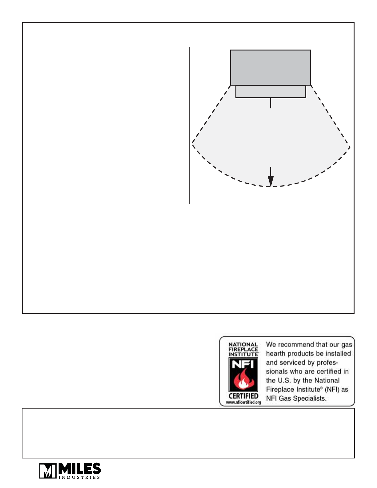
CAUTION—HOT! HOT! HOT!
This appliance is a HEATING appliance and it
becomes very hot when in operation.
UNDER ANY CIRCUMSTANCES, DO NOT
PLACE any object, furniture, draperies or
other item LESS THAN 36 inches (0.9 m) IN
FRONT OF THE FIREPLACE.
Fireplace
Hearth
CHILDREN and PETS
Radiant heat can heat surfaces such as the
hearth in front of the fi replace to temperatures
that, although approved safe, can be
quite uncomfortable to touch or step on—
particularly for children and pets. Children
and pets should always be supervised when
in the room where the appliance is located.
Remote control handset should be kept out of
reach of children. In the presence of children,
we STRONGLY RECOMMEND that you install
in front of the fi replace: a fi re screen or, to protect young toddlers, a “hearth gate”—see
Options on page 41.
HOT SURFACES
Be aware that, although safe, some combustible materials and fi nishes, even though
installed at listed clearances may, over time, shrink, discolor, warp or show cracks. The
1300I requires the installation of the cement board provided with the engine.
Convective heat will exit the unit and travel up the wall surface if not impeded. Protruding
mantels and projections can help direct the heat away from the wall. AVOID PLACING heat
sensitive items such as televisions, paintings, decorations, etc. above fi replaces or near the
edge of protrusions unless appropriate.
furniture or other objects
in this space in front of
Do not put
the replace:
36” (0.9 m)
The information contained in this installation
manual is believed to be correct at the time of
printing. Miles Industries Ltd. reserves the right to
change or modify any information or specifi cations
without notice. Miles Industries Ltd. grants no
warranty, implied or stated, for the installation
or maintenance of your heater, and assumes no
responsibility for any consequential damage(s).
Designed and Manufactured by / for
Miles Industries Ltd.
190–2255 Dollarton Highway, North Vancouver, BC, CANADA V7H 3B1
Tel. 604-984-3496 Fax 604-984-0246
www.valorfi replaces.com
© Copyright Miles Industries Ltd., 2011
2
Safety and Your Fireplace
Safety and Your Fireplace
Please Read and Carefully Follow all Safety Warnings and
Operating Instructions Contained in Your Owners Manual
(Replacement Manuals are available by contacting our service department at
1-800-468-2567 or visit www.valorfi replaces.com).
Please Follow These Important
Child Safety Precautions and
Recommendations,
• Parts of your Valor Fireplace become
extremely hot while in operation.
• The glass viewing window
temperature can
exceed 500 F
at full capacity.
Momentary contact
with a hot glass
surface can cause
a severe burn, even if the fi replace
is operating at reduced heating
capacity.
• The glass window will remain hot
for an extended period of time after
the fi replace has been turned off.
Ensure that children are prevented
from touching the fi replace during the
cool down period.
withdraw in the event of accidental
contact with a hot surface.
• A physical barrier is strongly
recommended if there are young
children, or at-risk individuals in the
house. Install an approved aftermarket safety gate to keep toddlers,
young children and other at-risk
individuals a safe distance from the
fi replace.
• Keep the remote control handset
out of reach of children at all
times. A wall mount storage holster
is provided with your remote control
handset.
• Ensure that the fi replace, including
the pilot light, is completely turned
off when children are present and
close supervision and safety barriers
are not available—see page 36 of
Owner’s Information section.
• Toddlers and Y oung Children
must be closely supervised at all
times when they are in the same
room as the operating fi replace. They
lack full awareness of danger and
rely on your protection. Toddlers,
in particular, do not have the motor
skills and response refl exes to
• If the fi replace is not going to be used
for the summer or any extended
period of time, remove the batteries
from the remote control handset
and receiver. It is recommended that
batteries are replaced annually in any
event—see page 35.
3

Table of Contents
Safety and Your Fireplace .............................................................................3
Safety and Warning Information...................................................................5
Specifi cations ................................................................................................8
Overview .........................................................................................................9
◊
Dimensions ..................................................................................................10
Location ........................................................................................................10
Mantel Clearances .......................................................................................11
Framing & Hearth Requirements ................................................................13
Venting ..........................................................................................................15
Co-Axial Venting ..........................................................................................16
Co-Linear Venting ........................................................................................20
Installation Planning ....................................................................................21
Appliance Preparation .................................................................................22
Window Removal .........................................................................................25
Supply Gas installation ...............................................................................25
Ceramic Liners Installation .........................................................................27
Logs Installation (1300IL) ............................................................................28
Rocks Installation (1300IR) .........................................................................29
Window Refi tting .........................................................................................31
Remote Control Initial Set-up .....................................................................31
Operation Check & Aeration Settings Adjustment ...................................32
Remote Control Handset Wall Holder Installation ....................................32
Owner’s Information ....................................................................................33
◊
Remote Control Operation ..........................................................................37
◊
Options .........................................................................................................41
Lighting Instructions ...................................................................................42
Wiring Diagram ............................................................................................43
Approved Venting Components .................................................................44
◊
Warranty .......................................................................................................46
Spare Parts ...................................................................................................47
= Updated content
◊
4
Safety and Warning Information
OWNER’S INFO
READ and UNDERSTAND all instructions carefully
before starting the installation. FAILURE TO
FOLLOW these installation instructions may result in
possible fi re hazard and will void the warranty.
Prior to the fi rst fi ring of the fi replace, READ the
Owner’s Information section of this manual.
DO NOT USE this appliance if any part has been
under water. Immediately, CALL a qualifi ed service
technician to inspect the unit and to replace any part
of the control system and any gas control that has
been under water.
THIS UNIT IS NOT FOR USE WITH SOLID FUEL.
Installation and repair should be PERFORMED
by a qualifi ed service person. The appliance and
venting system should be INSPECTED before initial
use and at least annually by a professional service
person. More frequent cleaning may be required due
to excessive lint from carpeting, bedding, etc. It is
IMPERATIVE that the unit’s control compartment,
burner, and circulating air passageways BE KEPT
CLEAN to provide for adequate combustion and
ventilation air.
Always KEEP the appliance clear and free from
combustible materials, gasoline, and other fl ammable
vapors and liquids.
NEVER OBSTRUCT the fl ow of combustion and
ventilation air. Keep the front of the appliance CLEAR
of all obstacles and materials for servicing and proper
operation.
Due to the high temperature, the appliance should be
LOCATED out of traffi c areas and away from furniture
and draperies. Clothing or fl ammable material
SHOULD NOT BE PLACED on or near the appliance.
Children and adults should be ALERTED to the
hazards of high surface temperature and should STAY
AWAY to avoid burns or clothing ignition.
This unit MUST be used with a vent system as
described in this installation manual. NO OTHER vent
system or components MAY BE USED.
This gas fi replace and vent assembly MUST be
vented directly to the outside and MUST NEVER be
attached to a chimney serving a separate solid fuel
burning appliance. Each gas appliance MUST USE
a separate vent system. Common vent systems are
PROHIBITED.
INSPECT the external vent cap on a regular basis to
make sure that no debris, plants, trees, shrubs are
interfering with the air fl ow.
The glass door assembly MUST be in place and
sealed before the unit can be placed into safe
operation.
DO NOT OPERATE this appliance with the glass
door removed, cracked, or broken. Replacement of
the glass door should be performed by a licensed or
qualifi ed service person. DO NOT strike or slam the
glass door.
The glass door assembly SHALL ONLY be replaced
as a complete unit, as supplied by the fi replace
manufacturer. NO SUBSTITUTE material may be
used.
DO NOT USE abrasive cleaners on the glass door
assembly. DO NOT ATTEMPT to clean the glass door
when it is hot.
TURN OFF the gas before servicing this appliance.
It is recommended that a qualifi ed service technician
perform an appliance check-up at the beginning of
each heating season.
Any safety screen or guard removed for servicing
MUST BE REPLACED before operating this
appliance.
DO NOT place furniture or any other combustible
household objects within 36” of the fi replace front.
YOUNG CHILDREN should be CAREFULLY
SUPERVISED when they are in the same room as
the appliance. Toddlers, young children and others
may be susceptible to ACCIDENTAL CONTACT
BURNS. A physical barrier is recommended if there
are at risk individuals in the house. To restrict access
to a fi replace or stove, INST ALL AN ADJUSTABLE
SAFETY GATE to keep toddlers, young children and
other at risk individuals out of the room and away
from hot surfaces.
BE CAREFUL not to put any decorating objects
sensitive to heat to close above or around the
fi replace as it gets very hot when operating.
DO NOT use this heater as a temporary source of
heat during construction.
This appliance is a DOMESTIC ROOM-HEATING AP-
PLIANCE. It must not be used for any other purposes
such as drying clothes, etc.
5

OWNER’S INFO
Safety and Warning Information
HOT SURFACES. Be aware that, although safe,
some combustible materials and fi nishes, even
though installed at listed clearances may, over time,
shrink, discolor, warp or show cracks. The 1300I
requires the installation of the cement board provided
with the engine.
Convective heat will exit the unit and travel up the
wall surface if not impeded. Protruding mantels and
projections can help direct the heat away from the
wall. AVOID PLACING heat sensitive items such
as televisions, paintings, decorations, etc. above
fi replaces or near the edge of protrusions unless
appropriate.
Radiant heat can heat surfaces such as the hearth in
front of the fi replace to temperatures that, although
approved safe, can be quite uncomfortable to
touch or step on—particularly for children and pets.
Accessory screens and guards will reduce the radiant
heat on these surfaces.
Operating Your Fireplace for the First Time
When operating your new fi replace for the fi rst time,
some vapors may be released due to the burning of
curing compounds used in the manufacture of the
appliance. They may cause a slight odor and could
cause the fl ames to be the full height of the fi rebox, or
even slightly higher, for the fi rst few hours of operation.
It is also possible that these vapors could set off any
smoke detection alarms in the immediate vicinity.
These vapors are quite normal on new appliances. We
recommend opening a window to vent the room. After
a few hours use, the vapors will have disappeared and
the fl ames will be at their normal height.
State of Massachusetts Carbon Monoxide
Detector/Vent Terminal Signage
Requirements
For all side wall horizontally vented gas fueled
equipment installed in every dwelling, building or
structure used in whole or in part for residential
purposes, including those owned or operated by the
Commonwealth and where the side wall exhaust
vent termination is less than seven (7) feet above
fi nished grade in the area of the venting, including
but not limited to decks and porches, the following
requirements shall be satisfi ed:
1. INSTALLATION OF CARBON MONOXIDE
DETECTORS. At the time of installation of the side wall
horizontal vented gas fueled equipment, the installing
plumber or gas fi tter shall observe that a hard wired
carbon monoxide detector with an alarm and battery
back-up is installed on the fl oor level where the gas
equipment is to be installed. In addition, the installing
plumber or gas fi tter shall observe that a battery
operated or hard wired carbon monoxide detector
with an alarm is installed on each additional level of
the dwelling, building or structure served by the side
wall horizontal vented gas fueled equipment. It shall
be the responsibility of the property owner to secure
the services of qualifi ed licensed professionals for the
installation of hard wired carbon monoxide detectors.
a. In the event that the side wall horizontally vented
gas fueled equipment is installed in a crawl space or
an attic, the hard wired carbon monoxide detector with
alarm and battery back-up may be installed on the next
adjacent fl oor level.
State of California. Proposition 65 Warning.
Fuels used in gas, wood-burning or oil fi red appliances,
and the products of combustion of such fuels, contain
chemicals known to the State of California to cause
cancer, birth defects and other reproductive harm.
California Health & Safety Code Sec. 25249.6.
6
b. In the event that the requirements of this subdivision
can not be met at the time of completion of installation,
the owner shall have a period of thirty (30) days
to comply with the above requirements; provided,
however, that during said thirty (30) day period, a
battery operated carbon monoxide detector with an
alarm shall be installed.
2. APPROVED CARBON MONOXIDE DETECTORS.
Each carbon monoxide detector as required in
accordance with the above provisions shall comply
with NFPA 720 and be ANSI/UL 2034 listed and IAS
certifi ed.

Safety and Warning Information
OWNER’S INFO
3. SIGNAGE. A metal or plastic identifi cation plate
shall be permanently mounted to the exterior of the
building at a minimum height of eight (8) feet above
grade directly in line with the exhaust vent terminal for
the horizontally vented gas fueled heating appliance
or equipment. The sign shall read, in print size no less
than one-half (1/2) inch in size, “GAS VENT DIRECTLY
BELOW. KEEP CLEAR OF ALL OBSTRUCTIONS”.
4. INSPECTION. The state or local gas inspector of
the side wall horizontally vented gas fueled equipment
shall not approve the installation unless, upon
inspection, the inspector observes carbon monoxide
detectors and signage installed in accordance with the
provisions of 248 CMR 5.08(2)(a)1 through 4.
(b) EXEMPTIONS: The following equipment is exempt
from 248 CMR 5.08(2)(a)1 through 4:
1. The equipment listed in Chapter 10 entitled
“Equipment Not Required To Be Vented” in the most
current edition of NFPA 54 as adopted by the Board;
and
2. Product Approved side wall horizontally vented
gas fueled equipment installed in a room or structure
separate from the dwelling, building or structure used in
whole or in part for residential purposes.
(c) MANUFACTURER REQUIREMENTS - GAS
EQUIPMENT VENTING SYSTEM PROVIDED.
When the manufacturer of Product Approved side
wall horizontally vented gas equipment provides a
venting system design or venting system components
with the equipment, the instructions provided by the
manufacturer for installation of the equipment and the
venting system shall include:
1. Detailed instructions for the installation of the venting
system design or the venting system components; and
2. A complete parts list for the venting system design or
venting system.
(d) MANUFACTURER REQUIREMENTS - GAS
EQUIPMENT VENTING SYSTEM NOT PROVIDED.
When the manufacturer of a Product Approved side
wall horizontally vented gas fueled equipment does
not provide the parts for venting the fl ue gases, but
identifi es “special venting systems”, the following
requirements shall be satisfi ed by the manufacturer:
1. The referenced “special venting system” instructions
shall be included with the appliance or equipment
installation instructions; and
2. The “special venting systems” shall be Product
Approved by the Board, and the instructions for that
system shall include a parts list and detailed installation
instructions.
(e) A copy of all installation instructions for all Product
Approved side wall horizontally vented gas fueled
equipment, all venting instructions, all parts lists
for venting instructions, and/or all venting design
instructions shall remain with the appliance or
equipment at the completion of the installation.
7
INSTALLATION
Specifi cations
Approval & Codes
This appliance is certifi ed to ANSI Z21.88-2009/
CSA 2.33-2009 American National Standard / CSA
Standard for Vented Gas Fireplace Heaters for use in
Canada and USA, and to CGA 2.17-91 High Altitude
Standard in Canada. This appliance is for direct vent
installations.
This appliance complies with CSA P4.1-09 Testing
method for measuring annual fi replace effi ciencies.
The installation must conform to local codes or, in the
absence of local codes, with the National Fuel Gas
Code, ANSI Z223.1 or the Natural Gas and Propane
Installation Code CAN/CGA-B149. Only qualifi ed
licensed or trained personnel should install this
appliance.
This appliance must be electrically grounded in
accordance with local codes, or, in the absence of local
codes, with the National Electrical Code, ANSI/NFPA
70 or the Canadian Electrical Code, CSA C22.1.
Ratings
Model NP
Gas Natural Propane
Altitude (Ft.)* 0-4,500 feet*
Input Maximum (Btu/h) 30,000 28,000
Input Minimum (Btu/h) 6,500 14,500
Manifold Pressure (in
w.c.)
Minimum Supply
Pressure (in w.c.)
Maximum Supply
Pressure (in w.c.)
Main Burner Injector
Marking
Pilot Injector Marking #51 #30
Min. Rate By-Pass Screw #125 #125
3.7” 10.5”
5” 11”
10” 14”
Cat #
82-850
Cat #
92-300
For installations at elevations above 4,500 feet
(1,370 m) in Canada, please consult provincial
and/or local authorities having jurisdiction.
Supply Gas
Heater engines 1300ILN and 1300IRN are used with
natural gas.
Heater engines 1300ILP and 1300IRP are used with
propane gas.
The supply pressure must be between the limits shown
in the Ratings section above.
X
The supply connection is 3/8” NPT male and located
on the left hand side of the fi rebox. A shut-off valve (not
supplied) is required on the supply line to isolate the
unit during service.
Conversion Kits
The 1300 Vogue is supplied as natural gas or propane
gas and is fi eld convertible between fuels. See instructions
packaged with the conversion kit for further information.
Electrical
The 1300 does not require an electrical power source
to operate as a heater. However, it requires electrical
power to operate optional 1355LHK Lighting Harness
Kit or 1270RBK Remote Blower Kit.
*High Altitude Installations
Input ratings are shown in BTU per hour and are
certifi ed without deration for elevations up to 4,500 feet
(1,370 m) above sea level.
For elevations above 4,500 feet (1,370 m) in USA,
installations must be in accordance with the current
ANSI Z223.1 and/or local codes having jurisdiction.
Heating value of gas in some areas is reduced to
compensate for elevation—consult your local gas
utility to confi rm.
8
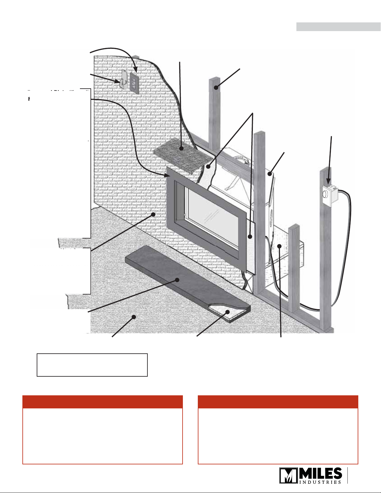
Overview
S
nd Pla
te
(
if
d)
F
p
ag
2
4
N
:
may
n
g
6CSK C
stallation Kit
,
si
de
:
nstall over bare fi shed
e,
Wa Fh
Any fi
board must be
HOT HEARTH / FLOOR! The hearth or fl oor
in front of the fi replace may become very
hot when the fi replace heats. Do not use the
hearth as a seat or shelf. Solid wood fl ooring
in front of the fi replace (if allowed) may
shrink during the heating season due to heat.
Some materials or items, although safe,
may discolor, shrink, warp, crack, peel, and
so on because of the heat produced by the
fi replace. Avoid placing candles, paintings,
photos, and other items sensitive to heat
around the fi replace.
INSTALLATION
Fire On/Off Wall
Switch (optional)
Remote Handset
Wall Holder
rrou
or options, see
o plate
o surround plate usin
137
n
urround plates
wall with any additional
tile, etc., butted up to or
installed overtop of the
365 and 1370 four-
ided surround plates:
ay install over fi nished
wall with or without til
tc. runni
Appliance
be installed with
lean Surround
335 three-sided
four-
urround plate.
behind the
urround plate.
use
3-2
es
Mantel—See Mantel Clearances
Framing—See Framing & Hearth Requirements
Cement Board—
See Surround Plate
requirements on page
23 for positioning of
cement board
1300I
t
Optional
Decorative
Light Dimmer
Switch—not
provided, see
your electrician
nishes applied over
ment
on-combustible. See
ve note on surround
lates when using tiles ,
Hearth. Non-combustible
as required—See Framing
& Hearth Requirements for
clearance
See pages 23-24 BEFORE
framing this appliance!
!
tc.
Combustible Floor
1/2” Insulation Board.
Required under noncombustible hearth
surfaces in some cases.
See Framing & Hearth
Requirements section.
WARNING
Some materials or items, although safe,
may discolor, shrink, warp, crack, peel, and
so on because of the heat produced by the
fi replace. Avoid placing candles, paintings,
photos, and other items sensitive to heat
around the fi replace.
Combustible Framing Allowed Beneath
Fireplace. When the appliance is installed
directly on carpeting, tile or other combustible
material other than wood fl ooring, the appliance
shall be installed on a metal or wood panel
extending the full width and recessed depth of
the appliance.
WARNING
HOT HEARTH / FLOOR! The hearth or fl oor
in front of the fi replace may become very
hot when the fi replace heats. Do not use the
hearth as a seat or shelf. Solid wood fl ooring
in front of the fi replace (if allowed) may
shrink during the heating season due to heat.
9

r
i
x
”
”
”
/
/
”
p
d
to
u
d
s
d
o
ad
cal
l
t
y)
cal
t
ly)
to Stand-Offs
as
63-3/4”
45”
45”
o C
le
Bac
n
INSTALLATION
Dimensions
21-5/8
6-5/8” dia. Venting
1-1/8
ente
neL
Electri
G
(for optiona
light onl
8”
-3
mbien
2
-1
43”
ero Clearance
t Top
ectri
(for optiona
mbien
t on
er
f he
e
of cement boar
i
er
n
”
37-1/2” to to
2-1/2
Location
10
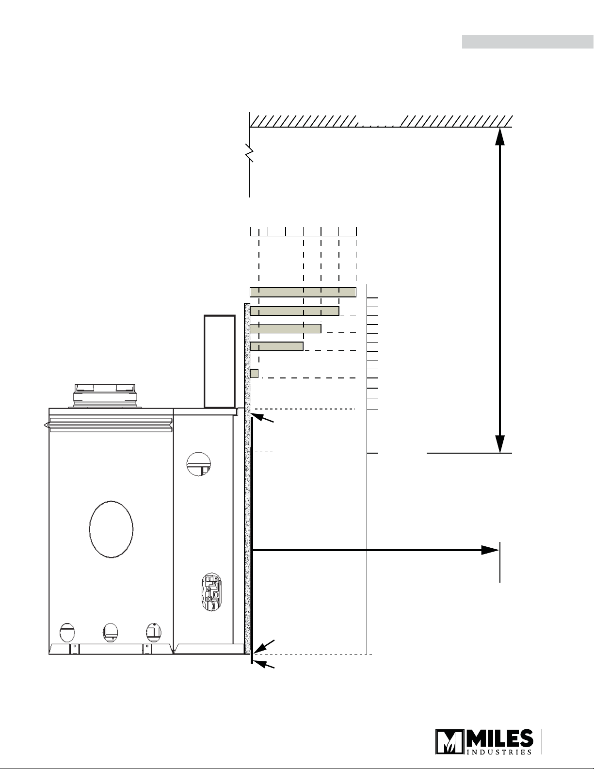
Combustible Mantel—Left Side View
Mantel Clearances
Mantel Projection
(from Face of Cement Board)
0 2” 4” 6” 8” 10” 12”
Ceiling
38”
36”
34”
32”
Mantel
Height
(from
Bottom
of Unit)
INSTALLATION
36” Min. to Ceiling
Firebox Height
Face of
Finished Wall
Fireplace
Opening
Bottom of Unit
29”
26”
21-1/8”
Do not put
furniture or objects
within 36” (914 mm)
of front of appliance
Four-Sided Trims, if used - extend
below bottom of unit (for dimensions, see
instructions packaged with trim)
Left Side View
11
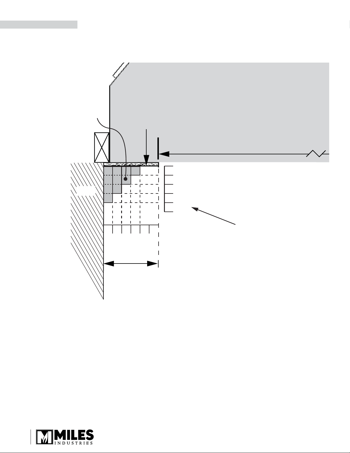
INSTALLATION
Combustible Sidewall / Mantel Leg—Top View
Shading denotes
allowable location
for combustible
mantel legs
Mantel Clearances
Face of
Finished
Wall
Wall
FIREPLACE
Fireplace Opening
32-1/2”
1”
2”
3”
4”
5”
2” 1”4”5” 3”
Min. 6”
between edge
of opening
and wall
Note
Right Side Clearances
are the same
Top View
12
Framing & Hearth Requirements
INSTALLATION
WARNING
SAFETY WARNING! The Vogue is a very effective radiant heater. The hearth/fl oor in front of
the heater can get very hot. Locating the unit raised above the hearth/fl oor or adding a generic
freestanding screen in front of the unit can greatly reduce hearth temperatures. When using a
3-sided trim or when the fi nishing does not include a trim, any hearth within 2 inches of the base of
the heater must be constructed of non-combustible materials (see diagrams in the following pages).
Note that some materials, although safe can degrade due to heat—take this into consideration when
choosing materials.
Rules
1. When using a 3-sided surround plate or no surround plate, any hearth/fl oor in front of fi replace less than 2 inches
from bottom of unit must be non-combustible and project a minimum distance of 9 inches. The hearth/fl oor must
have a non-combustible fi nish applied over the 1/2 inch insulation board provided with the 3-sided surround
plate 1335. Order separately if not using a surround plate. This insulation board acts as a thermal break.
2. Combustible baseboards (1 inch thick or less) located on wall below base of unit are acceptable.
3. a) With four-sided trims: Unit will need to be raised in every case by minimum of 1 inch to accommodate a four-
sided trim.
b) With three-sided trims or no trim: Bottom of heater must be at least 2 inches above combustible hearth/fl oor
fi nish in front. Non-combustible hearth applied over insulation board required if bottom of fi replace is less than
2 inches above combustible fl oor in front (see 1.).
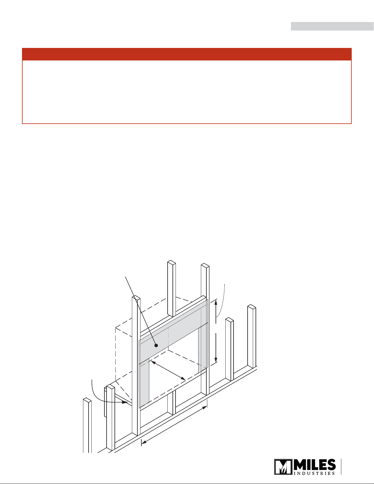
Framing Dimensions, unit raised on wall, without hearth
1/2” thick cement board required above and on
each side of engine (supplied w/engine)
Cement board at sides is not required
when using 1365 4-sided surround or
1370 4-sided surround
Combustible framing allowed
beneath fireplace. When
the appliance is installed directly
on carpeting, tile or other
combustible material other
than wood flooring, the appliance
shall be installed on a metal
or wood panel extending the
full width and recessed
depth of the appliance
21-1/2”
Between underside
of header and bottom
of firebox
36”
43-1/2”
13
bl
e
h
.
Wood is
d
w
INSTALLATION
Framing & Hearth Requirements
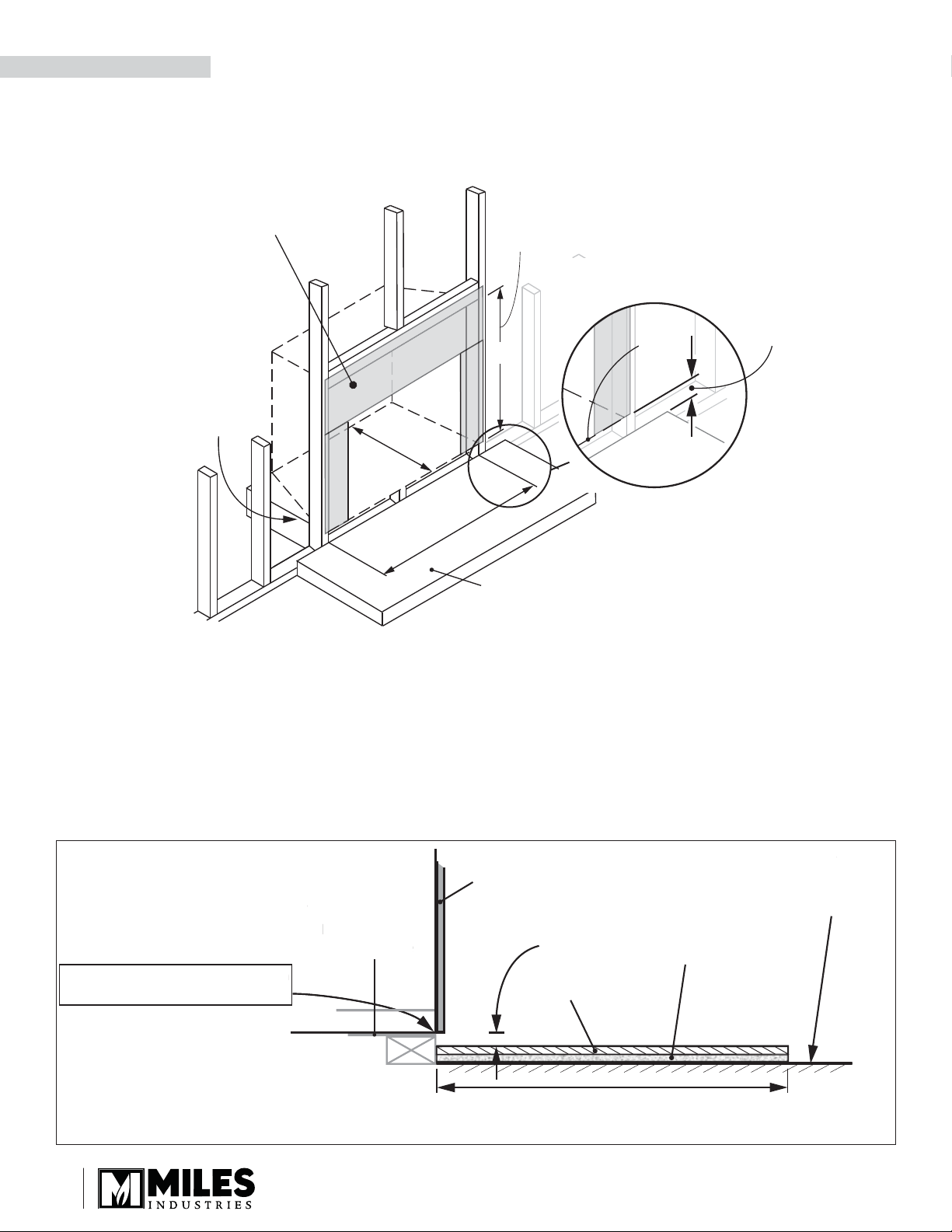
Framing Dimensions with Hearth
1/2” thick cement board required above and on
each side of engine (supplied w/engine)
Cement board at sides is not required
when using 1365 4-sided surround or
1370 4-sided surround
Combustible framing allowed
the appliance is installed directly
than wood flooring, the appliance
beneath fireplace. When
on carpeting, tile or other
combustible material other
shall be installed on a metal
or wood panel extending the
full width and recessed
depth of the appliance
21-1/2”
Between underside
of header and bottom
of firebox
Cement
Board
36”
Bottom of
firebox
Hearth
Min. 1” between top of
finished hearth and
bottom of firebox if using
#1337 Four-Sided Trim.
Min. 2-3/4” if using #1365 or
#1370 Four-Sided Surrounds.
43-1/2”
When using 3-sided surround plate or no surround
plate, any surface directly in front of the unit which
is at a height of less than 2” from the bottom of
the unit must be non-combustible extending
a minimum of 9” and have a 1/2” insulation board
beneath (supplied with 3-sided surround 1335 order insulation board separately if not using a
surround plate). See Non-combustible substrate
construction details diagram below.
Non-combustible substrate construction detail - Required when using 3-sided surround plates or
no surround plate and hearth/fl oor is within 2” of bottom of appliance
Surface of
rface of
Combustible
ombusti
Floor or Carpet
oor or Carpet
#1335 Three-Sided Trim is flush
-Sided Trim is flus
ottom of appliance
with bottom of appliance.
Wood is Allowed
Allowe
irectly Belo
Directly Below
ireplace
Fireplace
Three-Sided
Trims
Non-Combustible
Finish
Less
than
2”
1/2” Insulation
Board supplied
with 3-sided
surround plate
(excess may be cut off
or run below fireplace)
14
Min. 9” of hearth protection required if bottom
of heater is less than 2” above combustible floor
Venting
INSTALLATION
Vent Material
This unit is approved for installation using 4 x 6-5/8 in
co-axial direct vent pipe and accessories as listed in
the Approved Venting Components table on pages
44–45 of this manual. Follow the installation instructions supplied with the individual venting accessories.
This unit may also be converted to co-linear (2 x 3 in)
venting for use in solid-fuel burning fi replaces and
chimneys using adapters and accessories—see the
Approved Venting Components table on pages 44–45
of this manual.
Wall Thickness
The appliance vent is suitable for penetrating a combustible wall assembly up to 8 inches in thickness. A
non-combustible wall can be of any thickness up to the
maximum horizontal run of vent pipe allowed for the
particular installation.
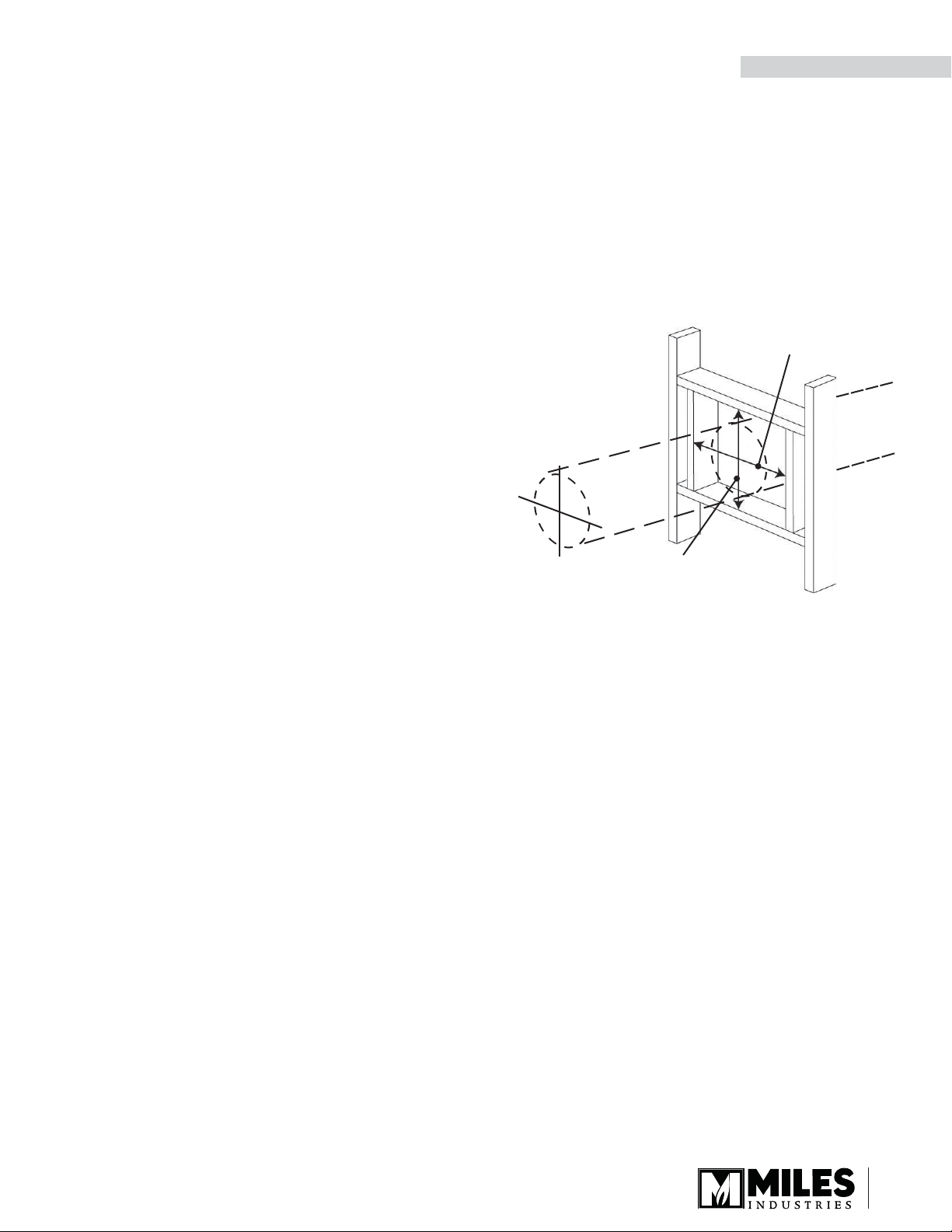
Framing Vent in Combustible Walls &
Ceilings
When penetrating through combustible walls and
ceilings, frame a minimum of 10 in x 10 in opening and
ensure that the insulation is kept clear of the vent pipe
using either a wall thimble or an attic insulation shield.
Follow the installation instructions supplied with the
individual venting components.
Align the vent
center to the
center of the frame
10” (254 mm)
10” (254 mm)
15
 Loading...