

Valor VENTANA Series, VENTANA 1200NCK, VENTANA 1200PCK Installation Instructions Manual
VENTANA
Gas Conversion Kit
1200PCK/NCK
Use with with Valor Models 1200 Heater ONLY
Installation Instructions
This appliance is certifi ed for use from 0–4500 feet. For
altitudes above 4500 feet, see local codes.
Kit Contents
1 Main burner
1 Pilot injector—see chart for identifi cation
1 Main burner elbow injector—see chart for
identifi cation
1 Minimum rate by-pass screw—see chart for
identifi cation
1 Set of conversion labels
1 Ceramic middle log (NG 4001370; LPG 4001534)
Tools Required
Wrenches, to disconnect gas line
•
• Phillips (+) screwdriver, to remove burner module
• Small (jewelers size) fl at blade screwdriver, to set
pressure
• Small fl at blade screwdriver, to release pressure tap
on valve
• Nut driver 8 mm or 5/16”, to remove burner nuts
• Needle nose pliers, to remove by-pass screw
• Hex (Allen) wrench, 4 mm or 5/32”, to remove pilot
injector
• Manometer, to set pressure when regulator is integral
with valve
WARNING
This conversion kit shall be installed by a
qualifi ed service agency in accordance with
the manufacturer’s instructions and all applicable codes and requirements of the authority
having jurisdiction. If the information in these
instructions is not followed exactly, a fi re, ex-
plosion or production of carbon monoxide may
result causing property damage, personal injury or loss of life. The qualifi ed service agency
is responsible for the proper installation of this
kit. The installation is not proper and complete
until the operation of the converted appliance
is checked as specifi ed in the manufacturer’s
instructions supplied with the kit.
Use this manual in conjunction with the installation manual supplied with the appliance.
Specifi cations
Model
Gas Natural Propane
Altitude (Ft.)* 0-4,500 feet*
Input Maximum (Btu/h) 36,000 31,000
Input Minimum (Btu/h) 15,000 15,000
Manifold Pressure (in w.c.) 3.6 10.5
Minimum Supply Pressure (in w.c.) 5.0 11.0
Maximum Supply Pressure (in w.c.) 11.0 14.0
Main Burner Injector Marking 82-1200 92-360
Pilot Injector Marking 62 30
Min. Rate By-Pass Screw 190 125
4001533-04
© Copyright Miles Industries Ltd., 2014.
1200NG 1200LPG
General Notes Regarding Conversion
The Ventana can be converted before or after installation into a wall. If converting after the fi replace is installed and
enclosed into the wall, the access to the minimum rate by-pass screw will require the removal of the burner module.
As well, the earlier version of the burner fi xing method to the burner module will require that the burner module be
removed—see section Burner.
There are two versions of the Ventana fi replace with respect to the manifold pressure regulation. Earlier versions
have a separate, convertible regulator that does not require a gas supply or a manometer to convert. Later versions
have a regulator integral with the control valve and require a gas supply and manometer to complete the conversion.
See section Manifold Pressure to determine which version you have.
Conversion Procedure
The conversion procedure will vary according to three factors.
• Whether the heater is already installed or not;
• Whether the burner mounting is considered an earlier model or later model;
• Whether the heater has a separate convertible regulator or a regulator integral to the valve.
The burner module assembly does not need to be removed from the
Burner Supports
fi xed from top
heater in the following case:
• The conversion is done before the heater installation, AND
• The burner mounting is a later model (fi xed to the burner tray from
the top side).
In ALL other cases, the burner module must be removed to proceed to
the conversion.
1. Remove the window, logs/pack and ceramic bricks (if installed) from the fi rebox.
2. Shut-off gas if unit is already installed and disconnect gas line at the regulator or valve depending on model.
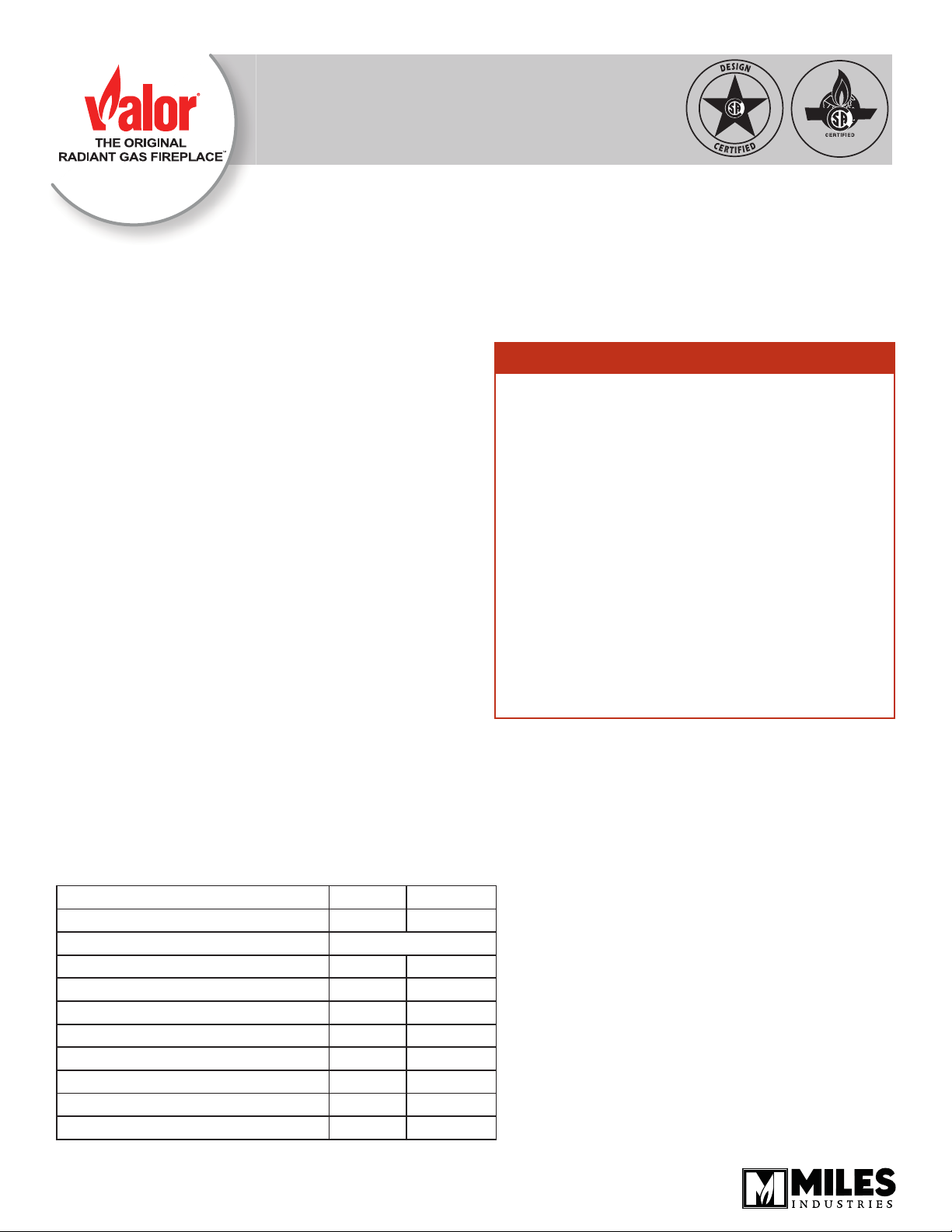
3. If the burner needs to be removed, remove the cast fret, front and rear brick supports—see fi gure 1.
4. Proceed to the following sub-sections.
Shut-off
Gas Supply
NG burner—cross-lighting ports
here
Disconnect
Gas Line
here
Remove Burner Module (12
4
screws + 1 at right hand side)
Burner
Top View
Remove
3
Rear Brick
Support (6
screws)
LPG burner—cross-lighting ports
2
Remove
1
Cast Fret
(2 screws)
Figure 1
2
Remove Front
Brick Support
(5 screws)
Burner
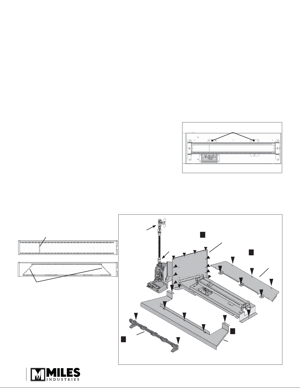
Early models—Burner fi xing nuts
accessible from underside of module
Early models: The burner fi xing points are under the
burner module tray and the burner module assembly
must be removed. Proceed as follows:
1. Remove the screw retaining burner module tray on
the right hand side as well as the 12 screws retaining
the module plate at the left side wall of the fi rebox—
see fi gure 1.
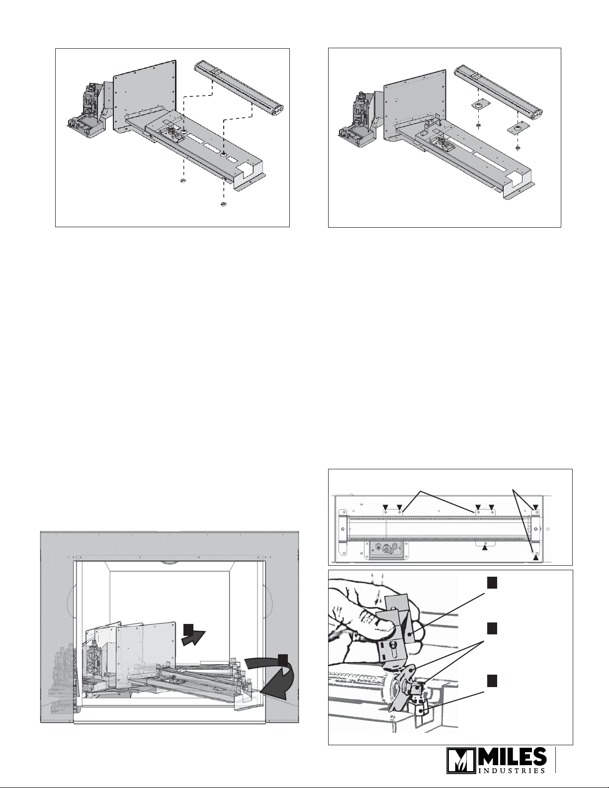
2. Grab the burner module assembly, lift it slightly, twist
it upward and slide it towards the right and out to
allow the valve and receiver attached to the module
end plate through the left inner fi rebox wall as shown
below.
3. Remove the front log retaining bracket from the
burner top at the right hand side and the injector
elbow with air shutter (NG) from the end of the
burner. Note that there is no air shutter on the LPG
burner. Unscrew the pipe nut while holding the
injector elbow with a wrench—see fi gure 2.
4. Remove the main burner by removing the two nuts
from the underside of the burner tray.
5. Replace the main burner by the appropriate fuel
burner fi xing it back to the burner tray with the two
nuts.
Later models—Burner fi xing supports
accessible from the top of module
Later models: The burner is fi xed to the burner tray
through two supports. The conversion can be done
without removing the burner module assembly from the
fi rebox.
1. Remove the front log retaining bracket from the
burner top at the right hand side.
2. Remove the injector elbow with air shutter (NG)
from the end of the burner. Note that there is no air
shutter on the LPG burner. Unscrew the pipe nut
while holding the injector elbow with a wrench—see
fi gure 2.
3. Remove the main burner by removing the fi ve
screws retaining the burner supports to the burner
tray.
4. Detach the main burner from its supports and attach
the supports to the replacing burner.
5. Refi t the new main burner to its position by fi xing the
burner supports back to the tray with the fi ve screws
previsously removed.
Remove burner from
tray (5 screws)
Remove front log retaining
bracket (2 screws)
1
Removing burner module from fi rebox
(fi rebox front transparent for clarity)
1
Remove front log
retaining bracket
3
Unscrew injector
elbow with air
2
shutter (NG) from
end of burner
2
Unscrew pipe
nut while holding
injector elbow
with wrench
Figure 2
3
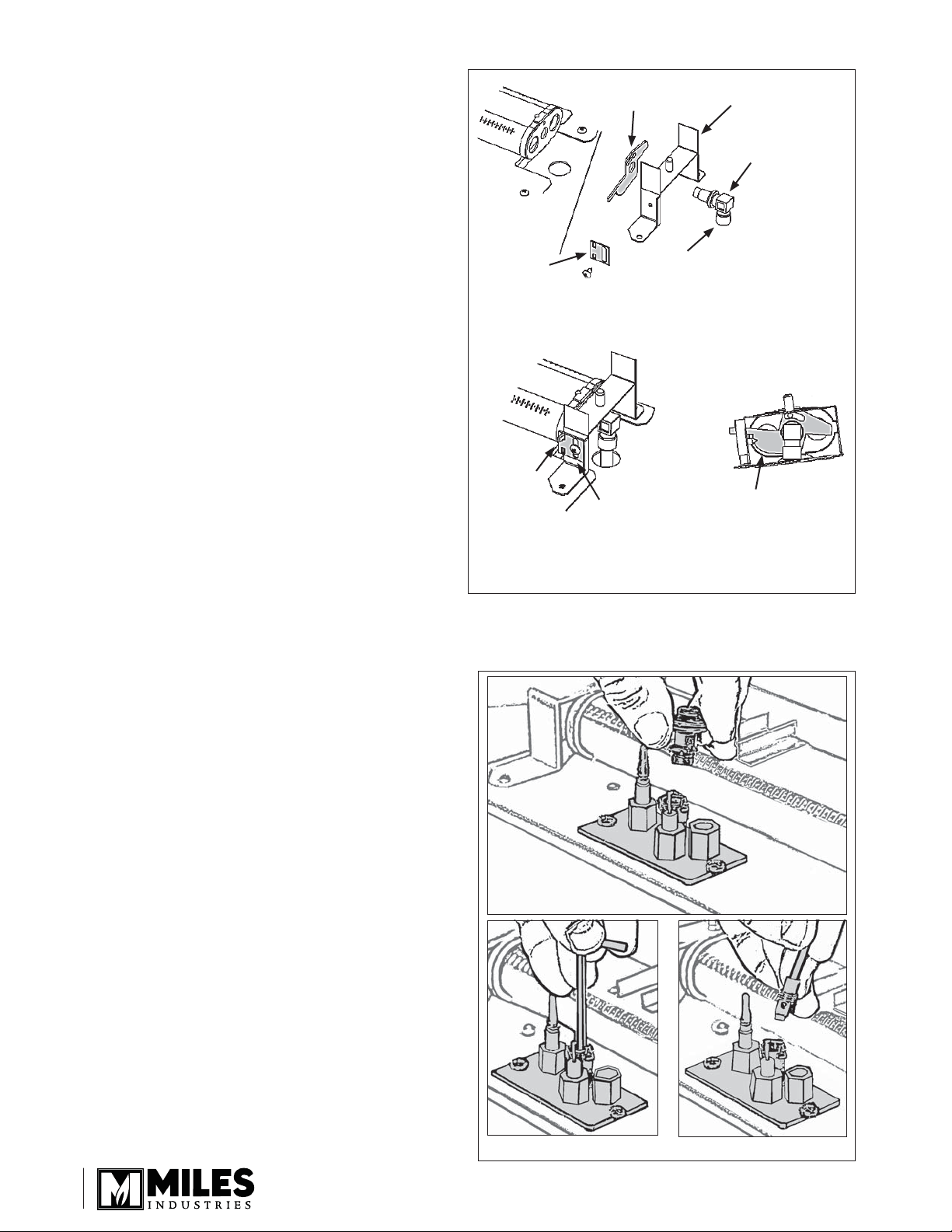
Injector Elbow
Reinstall the main burner injector elbow—see fi gure
3. Ensure the proper injector for the desired fuel type.
Note the catalogue number from the Specifi cations
table on page 1 and the same number stamped on the
side of the injector elbow.
• If converting to a LPG burner, DO NOT reinstall the
air shutter.
• If converting to a NG burner, install the air shutter
supplied with this kit as shown in fi gure 3.
Install air
shutter
slider (NG
units only)
Insert air
shutter
tab into
top hole
of slider
Install air shutter on
NG units only
Reconnect to pipe and
ensure it is gas-tight
Tighten screw
with slider at
mid-point in
slot
Re-install
log retaining
bracket
Thread injector
elbow through
air shutter (if
used) into end
of burner
Suggested air shutter
setting (NG units only)
Suggested NG
air shutter setting
Pilot Injector
1. Remove the pilot hood by pulling on it.
2. Unscrew the pilot injector using an Allen key. Discard
the pilot injector.
3. Replace with the appropriate pilot injector—see
Specifi cations table on page 1. Screw the new
injector.
4. Refi t the pilot hood by pushing down on it.
Figure 3
Figure 4
4
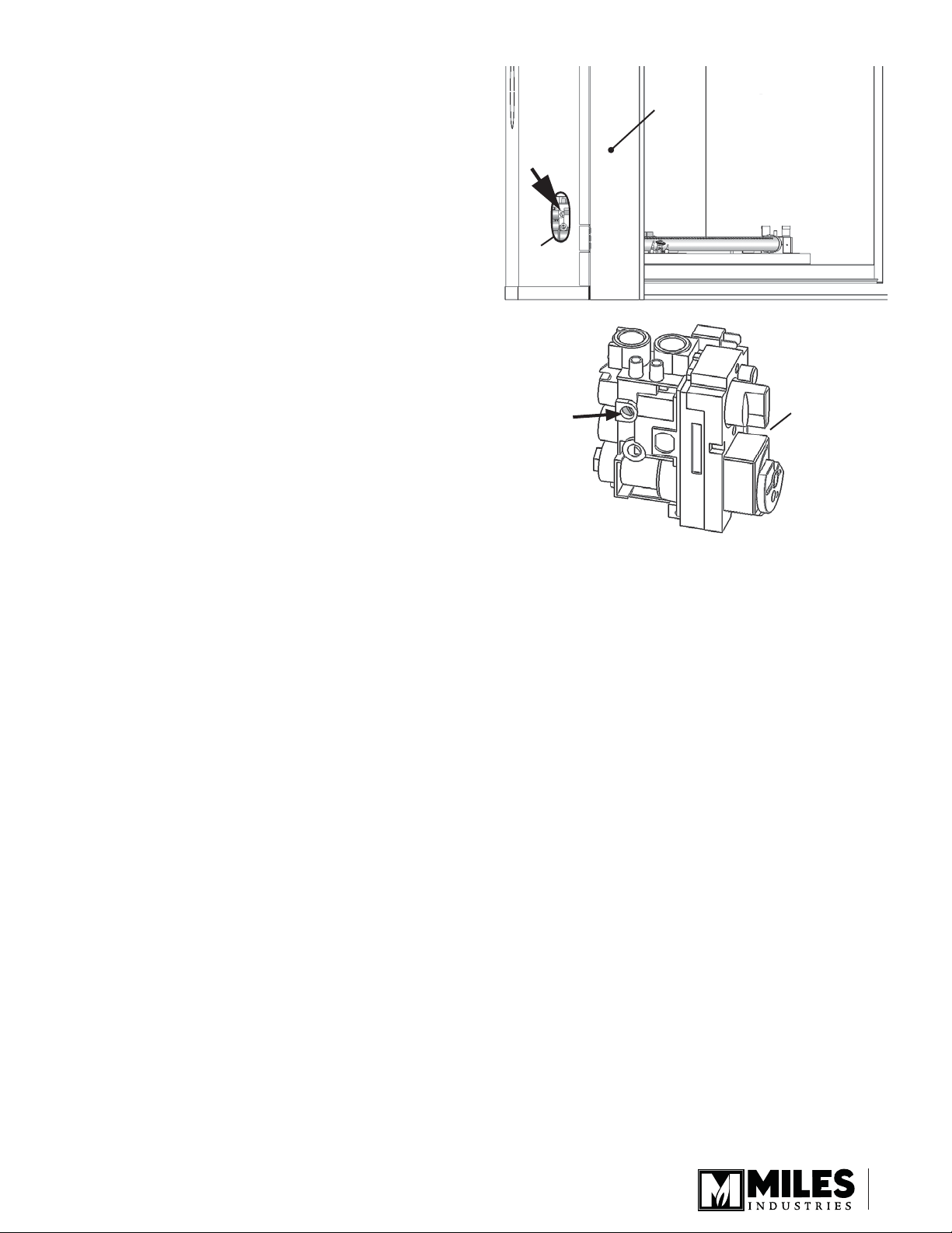
Minimum Rate By-Pass Screw
Convert the minimum rate by-pass screw accessing the
valve either when the burner is out of the fi rebox or from
the bottom hole of the exterior wall of the fi rebox, on the
left hand side of the fi rebox.
1. Remove the screw from the valve and discard. The
by-pass screw has a rubber O-ring and may need to
be pulled out using pliers after unscrewing.
2. Insert the replacement minimum rate by-pass screw
and hand tighten using a screwdriver. Refer to the
Specifi cations table on page 1 for proper by-pass
screw. Note that the number is stamped on the barrel
of the screw.
Firebox
left side
Opening
to access
the valve
Minimum rate
by-pass screw
location
Firebox
front
Front of
valve
Burner Reinstallation & Check
1. Reinstall the burner module if removed for
conversion.
2. Reinstall the rear brick support, the front brick support
and the cast grate.
3. Reconnect the gas line and the open shut-off valve.
Check for leaks.
5
 Loading...