

LU
a—
LL
LJJ
LU
-J
C..)
Cl)
Cl)
“li—I
S
.J).”.
•t
I
s.::-
S4
ggF
1.0
The
aoriat
I
Ministry
of
Lav’r,
;•
ro.;,rc
?
r
ur’
I
Siet
:sr
-‘il
ri
I..
.
s
al
f
the
B.C.
‘‘
“te’lation,
and
a
5
c”nfcrm
to
I
1.1
This
Jprfll,.r!.q
.•
“t’3’.t’.
-
onet
1P0
S
its
a’e.ted
v
hc
..
.
•
I
I
1.3
The
mninun
V.’ep’ace
;
installed
$
22
ig
7
least
15
from
the
b3sL
permanent
free
ooe”
sq/In)
(129
q/c
)
1.4
For
irstI
at,or
.
-
dlmeni
‘t
;
-
•
nto
whcr.
this
appliance
can
be
5
i
$
3
eep(oraheightofat
.f
the
fires
‘tee
Fig.
1).
The
miniasi
the
f,ie
:hali
6ot
be
less
than
20
-
k0N-:’MS.a
I3LE
nEARTH
with
minlmam
-
“Ii
widt
1.5
The
open
ireas
or
ter
‘de
or
at
ye
.te
top
of
the
VALORFLAME
hearth
box
flanges
ags
e
sealed
t”
the
fireplace
face
using
non-combustible
rterW
see
ite
2
4
for
suggested
methods).
1.6
Any
combustible
Gaflt
e
‘.‘
,helf
.1
itt
a
,in!mum
of
9
inches
clearance
above
the
r’.
Any
flue
damo
tc
wanner.
2.
ItT!
N
4
C
tnpck
t
TI.
f
-
•
.
r_
•
ad&’l*•a
arp
,,g.
.
•
,u
r’
aic
•t
It
‘s
ra
K
loqs,
coke,
•tr.i.h
are
4
r’
.,-ptr.er
with
te
dress
•
at
•
the
carton
‘l
£
c.
side.
p
I
I
I
I
A
1
t
I
‘0
t
b?ft
fireplace
i’
tsr
•nt
standards
UIS.
standards
-
1.2
Prior
t3
instal
i
I
spccttd
o
c
-
.
DC
inb’a!iv’
‘ii
approved
flu
1
r
gases
in
.he
Jiirrey
t
tie
‘
in.
stuldbesweptand
ndoosb
c.
t
ns
Inareasof
c
‘s
n.’
r°.,
‘te.
C.c
t!iat
the
Valorflame
‘
‘s
bu4it
:no
uuts’de
walrs
unless
an
t
a
ortnsation
of
flue
1.1
.1
w
01
‘cto
oc..
in
a
permanent
ci
at
V
4.
t
S.
a
a
0
V)
..C
4-)
o
s—
4-)
-
-o
ci
ci
C
2
4)
4-.—
ciQ
-D
-
4-)
>Qi
4.)
2
0
00w
2
CC
C
o
-w
-
2
—
4—
Ci
Li
ci.0
-
-
04-’
4-’
-u
ci
—C4-
ci
ci
4—’
0
Co
—
C
Ci
LI
>
(I)
Li
ci
0
0ci
2
o
24S.ci
Qi
C
—
U
ci
C
ci
ci
ci
ci
.o
-=
C
ci
C.
4-)
ciLI
-C
.00)
Cl
ci4-’
-u
4-
2
.C
ci
0
LI
ci
cci
0
0
ci
‘z
•—
4.)
-
6
S.L
-u
ci
ci
ci
DLiO
20
ci
>-‘
ci
C
Ic
rc4-’
5Qi
ci
Qioci
2
LI
.0
2
ci
s—’
4-
4.)
ci
-
ci
ci
ci
.0
C
-C
LIci
0
ci
I
Cci
cJ
ci
LI
Dc)
4-’
04-—
2
F
0
cicici
2
oo<
ci
—
(U
-C
—
-4-’
ci
•
I))
C4-’CJ
ci—
c_I
Li
ci03-’
Qici
—
XLc.,
ci4-
2
04-’
0)r
cit
CL
4-
DCLJ
ciQiOCi
LI)
01.0
4-)
2
ci
(IC)
-
ci
LI
ci
Li
Cl
,
-,-.
4-
=
2
>-,
i’
.)D>CJ
ID
.0
LI)
C
>,
ci
LI
D.C
ID
—
Li
0
L
ci
4—’
0
—
2
0
2
4—’
C
DC
Gi
-4—’
Ci
C
C
ci
S
—
LI
ci
.
ci
ci
ES
04-
ci
ci
ci—
C—)
2
4—
ci
2:
<ID
(—)
crc
LU
-J
crc
C)
cci
CD
cci
LU
0.
L/)
(1)
ci:
LU
=
H
>-
cci
LU
ci
LU
<ID
ci
LU
F-
ci
ci
Li
ci
U
ci.
LU
2:
ci
ci
:LI-
G)
-
02
(1)0
4-
.C
Lc
(U
(1)2
C)
CO
C
4—’
CL
C)
H-
0.0
Cl)
4)
0
LI
C)
2
4-
>
LI
ci
(1)
-C
ci
C)
4-
4-)
2
2
ci
0
ci
S.
<
Ci
0
2
CD
C)
4-’
..
ñ
0
.--
>,
4-
-C
Q)
.0
-
ci
C)
LU
—
(U
LI
44-
ci
ci
4-
4-
2
-—
4-
ci
-C
.J
t1
S.LI
(1)
.0
Ci
-‘-
-
C
Ci
5
LI
Ci
C
4-
LU
IX
0
ci
ci
2
4-
ci
S
ci
S.-
D
ci
-u
—
ci
0
ci
LI
•
4—
(1)
-4--’
<
ItS
C)
r
0.
>.
0
-—
0
0
C
ci
2
4—
4—)
—
vs
-u
0
4--
.
.ci
2:
LU
C
4-
)
-u
04-)
2
ci
C
ci
2
ci
0
Q4-04-LJcici
<0
-
02
0
+)
—
—
ci
4-
C)
ci
S.-
ci
-
2
LI
0
C
ci
.0
C)
LU
UI
.0
2
0
>,
-—
-
—
LI)
2
S.-
C
CL)
4-C
2:2:
4-’
•
002L,jL
xcicici—
“
CL
.0
C
‘is
4—
p---
•
S--.
4—’
LI)
2
Ci
ci
0
4..)
4—’
u
vs
LI
Q4)
0
<
ci
Li
LU
C)
(\J
ci
LI)
LI)
4-
.0.0
ci
.
—
C)
—
ci
4-’
—
0—
ci
2:
F-
Li
-u
vs
ci
LI)
LI
ci
4-)
-u
0
Li
t3
4)
C)
4—
<
-—
•
C)
C)
C
C
Ci
6
C
4-i
0
2
CiC.
C
DLULI01L
CQ
4-4-cicicicci
U
LI
ci
ci
0
C)
0
—
-
—
ci
ci
ci
C)
2
0
—
C
Ci
ci
4-
0.0.0
Li
HCD
LU
C
vs
—
C
ci
C
ci
F
Cl
4-
0
C
•
C
4-
C
2
—
vs
ci
—
Ci
ci
ci
0
5-
C)
-u
Ui
Lii
<
C)
Li
CL)
-‘
ci
-
C
C
—
C
—
—
ci
0
C
C
—
LI)
ci
CD
ci
-i-)
U)
C)
C)
LI
4-
C)
—
0
—
•
4-)
4-
•
U)
-ci
-C
-
—
LI)
ci
0
CD
.—
-—
C
0
C)
ci
-
.-
ci
ci
vs
—.
—
CJ
ci
0—
<
LU
4i.r
C
C)
-u
-
ci
ci
LI)
5
C
5-
ci
ci
—
C
ci
C)
C)
CL
Li
LU
-‘
F-
Li
Qi
4-’
-u
u
o
ci
-u
-—
ci
ci
ci
—‘
4-
LI
Li
><
H-
ci
4-
4-
vs
—
C)
—
C
C
—
.
-‘
ci
-u
>
<
-u
L/I
—
Li
ci
0
0
ci
-
5
—
ci
ci
4—’
ci
-
Ci
Cx$LUQci
ciQiQci-_
04-00
C
C
ciciQQi
)—rJci4-
ciL.0$Eci-.Q5-0Qici
C
ci
.0
>
LU
-—
ci
U.
2
i.)
.—
—
_
C
Di
0
-
Ci
LU
>
(U
-
—
0-—
ci
—
ci
ci
Ci
0
CL
C)
>
2
—
.—,
Li
I)
LI
<C
HIX
0
0
4-
0
ci
LI)
-u
ci-
LI)
Li
-4-’
ci
Li
Ci
U.
ci
0
ci
C
C
-i-—
D
<C
-—
Ci
4-
i-.--
ci
—
0-.-
C
C)
.
QiciLI000vsci(U_L
LI
ci
ci
Li
Cl
ci
ci
LU
0
.0
.0
Ci
H-
4-
-—
ci
C
ci
C)
Ci
Li
z
LI
—
C)
—
Ui
42:
CD
LI
—
4-
ci
0
4-
—
Ci
4-
>
Li
ci
C<
-4--’
—
LU
ci
-.--
C
C
t)
r)
vs
2
-)
0
I))
vs
4-
—
LU
ci
•
0
ci
ci
•
—
ci
4-
-—
—
0
C
ci
C)
U.
-—
w
ci
ci
H-
IX
4-
4.0
—
—
vs
4-
0
4-
4-
3-
C).
4-
.0
0
Li
—
U.
Cl
ci
Ci
2
-—
--
---
C
—
Ci
4-
-—
<<
Ci
LI
Liv)
CLI4-ci2:
><$o2
Dj-_)
—<CU.
(IciciciLU.
U.
vs
-—
-—
LI
—
LU
C)
2
0
x
0
ci
LI
C
.0
2
—
ci
C
4-
0
C
4--
ci
<C
ci
C)
C)
ci
C
0
2
C
4-)
CL
04-
—
U-
-.-
Cl
ci
0
F-
•
—
>
Otz
ci
-4-’
2
—
.0
-
—
ci
—
>
vs
CD
4-’
t)
0
—
<C
HLU
-4-’
U)
ci
U-
—
ci
4-
ci
Ci
LI
4—
‘U
Ci
C)
C4-
ci
C)Qici
L.CLICcivs.CCQELi.0Qi
—
0
ci
ci
>
5
ci
LU
F-
C)
U.
ci
0
-
—
4-
—
Li
ci
ci
LI
.C
Ci
0
ci
C)
CD
6
2
—
U.
LU
>
4-
Cl
—
5
4-
ci
3
-4-’
-
-C
ci
5
ci
vs
ci
Li
-H
0
ci
C
—
C1
C
U-
—
U.
C)
ci
LI
—
C)
H-
-
LI
Li
0
0
$
C)
-—
-
S
ci
-—
ci
ci
o
-
—
—
*
2
-)
-
4CC
ci
H-
ci
04-
Cl
.0
—
C)
LI
ci
&‘
0
Li
LI
4-ciQi(UQ)
01
—
UC
H-ci4-D.oci
Lcicici
LI
>
5-
>
—
Ci
Ci
)<
ci
><
C)
4-’
Ci
.0
-
—
ci
t7)
C)
LU
-4-’
t)
.—
U
—
ci
-
Ci
0
Li
Ci
0
LUC)
0
0
-C
CD
LU
>
..-)
4-
0
5
ci
5ci
-
ci
ci
Li
-w
ci
LI
.0
6
vs
ci
4-
—
tJ
CD
Li
—--
>
U
ci
Di
ID
CD
Cl
ci
Qi
.tJ
(I)
ci
LI
ci
C)
2
—
4-
C)
C
LI
ci
C
0
<C
4-_
‘U
—
ci
ci
—
—
•
C)
4-’
4-
5-
ci
CC
ci
—
4-
ci
ci
U)
i
C
C)
LI
CL
C
0
4-
C)
Ci
LI
.0
4-
5-
ci
Li
C)
—
ci
ci
>4)
0
U.Li2Q).0._oci.C
4-
cio
U
Q2ciU.F-LUciLQi
4-Q
ciLIvsci
0
4-
-C
C)
ci
-
S
ci
1)
U.
—
4-
LI
0
LI
4-
—
2:
LI
LI
vs
5
ci
C)
LI
4-
4-
4—
ci
C)
ci
C)
LU
—
LU
i
0
ci
C)
LI
0
0
Ci
Ci
4-
C
Ci
ci
(ID
CC
.0
U-
—
LU
ci
ci
C
LU
2:
2:
ci
—
CL
Li
U.
H4-
04--—
5
2:
Ci
>.,
—
C
4)_
to
V)
V)
4-’
-
.
S
V)4.)
Ca
C)cr)
—C)Cjto
o
c
Cl
S..
S..
4-)
L
-
C)C)
j
C)G)4.)
C
—cDE
WC-0
0
S..C
-
4.)
u
24-)
to
L
4.)
4-)
4.)
t3
to
4-
4-’
0
L)
C)CJC)0
4-
CC)
C)
—LErJc)
LiC)
C
0
0
0
C)
U
C)
C
.c
C)
0.
C)
04.)
—
C)
+
4.)
C)
-
.
(tjCCJ
4)
U
4-)
-
(C)
“‘-
0
(to
0)
(41
C)
C)
C)
0
—
o_
-—
Cl
C
Cl
v
L
0C)4-
0
0.
c>
..
C)
(1)
C
--
CiC>
“—4-
S..
S..
OC)
0
4-
S..
C)
S..
La
-G
.D
4-’
_
S..
0..
(41
CD
C)
C)
CO
_
.C
Lc
—
-
C.)
0
-‘-
4.)
Cl
(
Cl
4
toC)
Cl
Cl
4-
0
0
C)
L
(1(
4-’
C,1v
C.J4..
—E
(41
‘to
C)
C)
1)
—
“
-
-—
-
c
+-‘
La
Cl
Ut-4-.).
C)
CU-c
C)
C)
—
4-—
-
--
4-
U
C.
2--
C)
U
Cj
0
H-
__
La
)
‘
4-
a)
-)‘
C)
C)
C)
0
•
>
0
Cl
o
C)
—
-—
to
C
Cl
C)
0
0
4-
—
0
6
Cl
-_
•
0
L
0
La
6
Cl
to
L
C)
—
0
U
C
—
to
-—
C)
Cl
C)
4-
U
.
C
C)
Cl
—
U
La
U
>
U
0
*
2
0
C).
D
C)
0
-,
4-
C)
4-
C
—
Cl
(41
C.)
.C
U
C
C)
c
C)
U
-—
—
C)
Q)
CLCl
C)C)
-G
C)
—
—
—
o
—
4-
C)
Cl
•
to
C)
to
U
Cl
Cl
•
Cl
•—
0
C
2
•
C)
•
1
4-
C)
0
0
r
to
to
C)
C
CX,
Cl
.C
Cl
La
C’
Q
—
—
Cl
to
C)
C)
C)
S..
tD
C
.)
C)
—
4-
C
-
>
.
to
U
-
—
U
Cl
—
Cl
to
(41
—
(41
C
—
La
0
C)
to
C)
to
(41
C)
C)
C)
—
0
U
U
U
C
0
0
2
to
C)
C)
to
C)
4-)
C))
4-4
-
U
Cl
to
—
to
.C)
I
C)
-
0.
Cl
--
6
0
C
—
C)
C)
to
U
U
0
0
—
0
—
•
C
4-
C
o
S..
Ci
S..
(4ft
U.)
—
—
—
C)
0
to
.—
U
4-
0
U
4-
4-
0.
Cl
U
C)
Cl
U
,-
2
Cl
,
-G
0
——
0.
0
Cl
0
LI
0000
CE
U
C)
0
<
.
C)
—
C)
-
Cl
C)
LI
2
Cl
LI
4-
LI
C)
I
C)
,.
LI
>
C)
Cl
C)
-
C)
C)
C
0
U
Cl
C’
C
4.’
i
UI
LI
.
C)
C)
U
U
Cl
U
LI
—
LI
C
0
CU
La
0
—
U
C)
to
U
•
Cl
Cl
<
Cl
C
C
—
4-’
C
•
0
•
Cl
i
Ci
to
LI
C)
0
C
Cl
Cl
to
Cl
—
Ci
Cl
U
U
—
—
C)
0
Q
.,
to
C)
to
to
to
C)
—
C
U
(41
(41
£
-C)
La
Cl
U
Q
0
to
Cl
C’
Cl
LI
•
Cl
Cl
U
Cl
U
Cl
C’
C)
C
<
Cl
C)
C’
C)
Cl
x
LI
Cl
S..
C)
C)
C)
U
U
-
—
—
La
—
to
C)
C)
‘
Cl
U
-—
-
La
-—
—
—
C)
C)
0
C)
C)
C)
to
4
U
C’
C)
—
C)
U
2
‘
-
—
U
U
-
—
—
C)
-
C
Ci
to
C)
‘
°
C
-
—
—
-‘
6
La
C)
•
CU
U
C
-‘
0
to
E
C)
C)
toC)
CU--C)
ZC).
C
>
•
U)
C)
C)
>
U
—
>
—
U
‘
-.
Cl
—
-
—
o
Cl
U
Cl
C).
C)
C)
Ci
C)
LI
C)
to
2
U
l
2
La
6
C)
Cl
U
C)
—
—
0
—
C)
C
La
C)
:-
U
LI
—
U
4-
Ci
C)
Cl
Ci
—
—
Cl
‘,
LU
C)
(D
to
2
-•>
E
—0
C)
LajC)_C)
U
C)
(41
-
—
-—
I
LI
Ci
Cl
Cl
C
LI
LI
C)
‘
-
-
—
to
C)
to
‘
C)
4.)
C)
.c’
4-,
0’
(Xi
C)
5-
C)
C
C)
C)
to
$
C)
-C
0
4-)
LI
0
Cl
-J
-J
La
C)
C)
.C))
4-..
to
to
C).-.
.-..4-
to
U)
I
to
UI
Ci
5’-
La=H
LU
C
C
H
CiLaCi
Cl
La
4..
CU
U)
La
LI)
If)
LI
C)
C
C
d
(4-)
U
C
4-
4.)
Ii,
Ci
H-

I
iui
IioIs
1(11
ii1ptflJ
II
i
Uiiii%.
iiiii
Seal
ing
opening
top
and
1
I
I
I
surface
surrounding
I
to
cover
at
least
3”
sides
/
i3Oiii’i
9j
ii)
iflir’
ml
mm
ri
wide
deep
hiCk
406mm
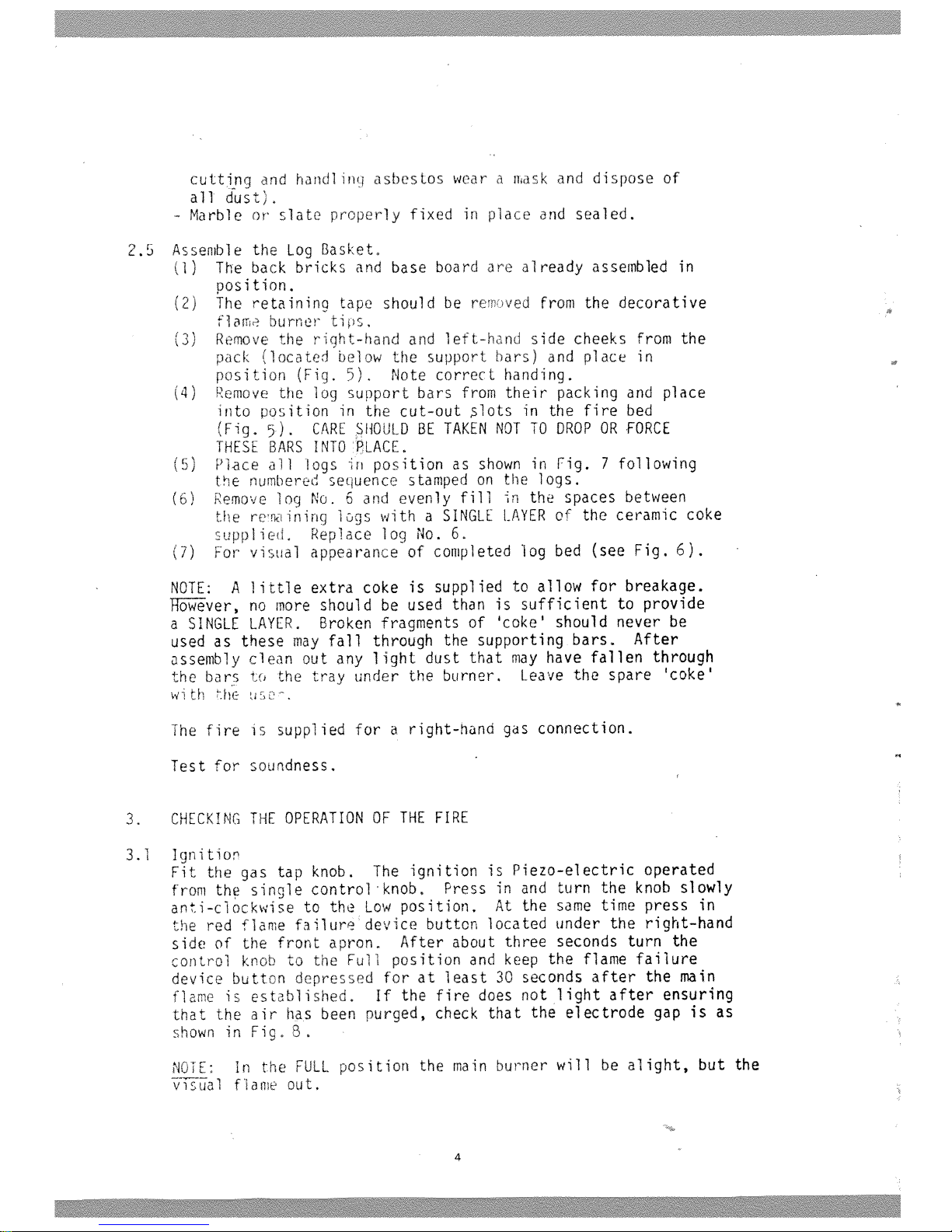
(16)
mm
Fig.
1
10”
(254mm)
minimum
for
a
height
of
at
least
15”
(380mm)
from
base
of
fire
Smmiir
liiirIti
HifliJi.
5
Fig.
2

E
Q
-
U
cc
2
0

BETWEEN
BARS
LOCATE
LUGS
ON
LOGS
5
6
/
FIg.
7

Test
pressure
at
“FULL”
position
cold
or
hot
ORIFICE
ALTITUDE
INPUT
Manifold
pressure
Inches
wg
Nrav
Cat
16
0
2000
250D0
60
2.4
Size
150
20004500
22,500
1
4.86
1,95
Check
gas
rate
at
meter
after
ten
rinutes
warm
up
in
“FULL”
position.
5.
FINAL
CASING
ASSEMBLY
5.1
Remove
the
nas
tap
knob,
5,2
The
hood
should
no
placed
overt
no
uope
section
of
the
hearth-
box
and
lowered
until
the
two
tans
at
the
rear
of
the
hood
have
entered
the
tlott
in
,
Ensure
that
the
hood
flanqes
rest
‘r
front
of
5.3
Oee
off
protective
fim
frow
s3o
irts
and
aaron.
The
left—hand
and
rqhthanc
:iOe
tr
irs
car.
toan
0
iteed
and
the
two
upper
fixing
screws
inserted
see
Fia,
3),
These
screws
also
fix
the
hood
in
uosition,
3
Tha
o.nr
ai
te
tne
loe
section
of
the
hearthbox
and
retoined
Lv
two
fixinq
screws,
one
at
each

side
(see
Fig.
3),
If
necessary
adju
t
the
two
levelling
screws
located
just
behind
the
front
legs
(Fi
3
3)
so
that
they
touch
the
hearth.
5.5
To
fit
the
dress
guard
place
the
lowers
oegs
into
the
holes
in
the
bottom
apron,
and
by
bowing
the
too
ic
te
the
upper
pegs
in
the
bosses
fastened
to
the
side
trims
‘Hq.
3).
5.6
Refit
the
qas
tap
knob.
6.
FINAL
OPERATiON
CHEC
Re-check
th
igntion
ann
opurate
trio
ire
on
all
settings.
NOTE:
The
pieces
of
coke
adjacent
t.
the
two
decorative
flame
may
be
adjusted
to
qive
the
be
rane
appearance.
7.
MAKE
SURE
THAT
THE
USER
KNOWS
THAT:
7.1
The
tap
must
be
pressed
in
nefore
tu
ry
anti-clockwise.
7.2
To
light
the
fire
the
tap
must
be
tu
d
to
the
fullest
extent
when
a
click
will
be
heard
from
the
ignition.
7.3
A
match
or
taper
may
be
used
to
ugh
th
fire
if
necessary.
7.4
Paper,
rubbish,
etc.
must
not
he
thron
on
to
the
fire
to
burn,
7,5
In
the
event
of
the
glass
front
pane
beirg
damaged
the
fire
should
he
turned
off
and
not
used
until
the
ass
has
been
replaced.
7.6
Should
it
be
necessary
the
coke
can
Le
replaced.
(Refer
to
the
Users
instructions).
7.7
The
fire
may
smell
slightly
for
a
per
od
due
to
its
newness.
7.8
A
flame
failure
device
button
is
bce
d
under
the
right
hand
side
of
the
front
apron
which
must
be
held
i
until
the
flame
is
estabi
ished.
9

BEFORE
ANY
SERVICING.
TURN
OFF
GAS
SUPPLY
TO
FIRE.
A.
TO
REPLACE
CERAMIC
toG(S)
OP
COKE:
To
remove
the
cress
nuard
(Fi0,
3’
spring
the
two
top
horizontal
lOgS
Out
of
their
chrome
olated
bosses
and
lift
the
guard
out
of
its
bottom
location.
The
log(s)
or
coke
can
now
be
removed
as
required.
Reolace
tne
logs
and
cake
as
shown
in
Fig.
7.
Replace
the
dress
guard.
B,
TO
REPLACE
THE
LOG
SUPPORT
BARS:
Proceed
as
Remove
all
the
logs
and
coke.
Remove
and
replace
the
log
support
bars
as
necessary
making
sure
that
no
piice
of
broken
small
cokes,
etc.
are
left
on
the
bed
under
the
support
bars.
Replace
logs
and
coke
as
previously
described
(Fig.
7).
C.
To
REMOVE
THE
BURNER/CONTROL
ASSEMBLY:
(i)
Remove
the
dress
guard
as
in
*A
(ii)
Pull
off
gas
control
knob
(iii)
Take
off
lower
casing
assembly
after
first
removing
the
fixing
screws
(iv)
Remove
fixing
screw
from
R,H,
vertical
trim.
Remove
trim.
(v)
Undo
flame
burner
pipe
from
brass
block
‘T’
piece
located
centrally
(Fig.
6)
(vi)
Disconnect
the
inlet
from
the
gas
tap
(vii)
Remove
fixing
screw
from
the
gas
tap
support
bracket
(located
on
R,H,
side
of
the
fire)
(viii)
51
ide
complete
burner/gas
tap
assembly
to
the
left
to
disengage
RH.
burner
location,
Withdraw
complete
assembly
by
rotating
slightly
toward
you
and
lifting
away
0.
TO
CHANGE
ORIFICE:
(i)
Proceed
as
‘C
(i)
to
(viii)
(ii)
Unscrew
the
old
orifice
and
replace
with
new
TAKE
CARE.
DO
NOT
ALLOW
JOINTING
COMPOUND
TO
GET
ON
TO
THE
CERAMIC
TIPS
IN
THE
ENDS
OF
THE
ORIFICE.
E.
SPARK
ELECTRODES:
(i)
Proceed
as
‘C’
(i)
to
(viii)
Disconnect
the
ignition
lead
from
the
electrode,
Remove
the
electrode
retaining
nuts
and
washers.
Remove
and
replace
the
electrode
assembly
oositioning
the
electrode
as
shown
in
Fig.
F.
PIEZO
GENERATOR:
(i)
Proceed
as
‘C
i)
to
(iv),
The
piezo
generator
can
be
changed

with
the
tap
in
position
in
the
fire.
Disconnect
igition
lead
from
igniter.
Carefully
remove
the
two
top
screws
in
the
gas
tap
niting
plate
and
lift
off,
taking
care
not
to
lose
the
spring.
The
new
piezo
generator
and
niting
plate
unit
can
now
be
fitted
in
the
reverse
order,
making
sure
that
the
head
work
is
correctly
located
in
the
plug
key
slots.
C.
GAS
TAP
PLUG
(GREASING):
Turn
the
tap
to
‘OFF
Remove
the
two
niting
headwork
assembly
off,
a
screwdriver
into
the
withdraw.
Ensure
that
regreasing
and
use
the
assemble
using
reverse
of
the
plug.
position.
Proceed
as
‘C’
Ci)
to
(iv).
screws
and
shakeproof
washers
and
lift
the
taking
care
not
to
1OSC
the
spring.
‘
Insert
slot
in
the
piuo,
twist
to
loosen,
then
the,
tap
orifices
are
not
blocked
when
minimum
amount
of
grease
possible.
Re-
procedure,
ensuring
the
correct
location
H.
TO
REPLACE
GLASS
FRONT
PANEL:
Remove
dress
guard,
gas
control
knob,
lower
casing
assembly
and
right-hand
vertical
trim
as
described
in
‘C
above.
Remove
two
screws
holding
right
hand
glass
retaining
bracket.
Remve
damaged
or
broken
glass.
Take
new
glass
and
fit
into
top
left
hand
retaining
bracket.
Replace
righthand
bracket,
securing
firmly
with
the
two
screws
replace
other
parts.
IMPORTANT:
ALWAYS
test
all
qos
joints
for
soundness
after
any
dismantling
or
exchange
procecure.

KeyNo
0
[
cf
M8kers
Pert
No
—
I
640K135
I
640K136
I
630K222
640K137
640K134
T
I
54O138
:NG
UMITE
B
9iP
ENGLAND
‘S
4
i1
I)
1
T3
j2l
8
OAT
LIST
GAS
FIT
EH
[I
f/IF
?
14
520A444
730K020
640K139
T
?20K521
i—i
1—
-—
-
—
620437
I
44OO4S
32Q’9p5
 Loading...