

Valor Ultimate Turbochim BR517S, ULTIMATE TURBOCHIM 517SF Installer's Manual
INSTALLER GUIDE
MODEL BR517S
(G.C.32-032-12)
ULTIMATE TURBOCHIM*
Side Fan Flued
Inset Gas Fire
*Covered b y GB Patent 2.202.622B
Please ke e p in a safe p l ac e for fut ur e r e fe r e n c e
600B313/02

Please leave this Installer Guide with the user
As supplied, this appliance is for use with natural
gas (G20)
When converted using Valor conversion kit
no.591149 this appliance is for use with propane
gas (G31)
This appliance is for use in the United Kingdom
(GB) and the Republic of Ireland (IE) only.
CUSTOMER CARE
This Installer Guide gives sufficient details to enable the appliance to be installed
and maintained. If further information is required, our Valor AdviceLine will
be pleased to hel p.
Please telephone 0345 626341 (Local call rates apply)
2

CONTENTS
Page
Appliance data 4
General in s tallation requiremen t s 5-9
Contents of packs 10
Preparing applian c e f o r installation 11
Electrical in s tallation 12
Gas supply & flue duct siting 13-14
Fan box ins t allation 15
Flue duct in stallation 16-19
Electrical tests 20
Terminal gu arding 21
Front surround & gas s upply inst allation 22-23
Ceramic coals & walls inst allat ion 24-25
Full operatin g c h e c ks 26-27
• Control settings check
• Spillage chec k
• Flame supervision & monitoring system check
Final review 28
Servicing & parts replacem ent 29-32
• Burner plaques replace ment
• Front surround rem o val
• Pilot unit removal
• Burner un it removal
• Gas tap, F.S.D. & solenoid removal
• Piezo ge n erator rem o val
• Main burner elbow injector removal
• Fan switch re moval
• Electrical control components access
• Distribution block removal
• Air press u re switch rem o val
• Fan removal
Short list of spares 33
26
26-27
27
29-30
30
30
30
31
31
31
31
31-32
32
32
32
3
PART1: APPLIANCE DATA
This pro duct u ses fu el effect pieces. It makes sen se to ta ke care when ha ndling
these articles to ensure that the release of dust is kept to a minimum
This appliance do es not contain any co m p o nent manufacture d from asbes t os o r
asbestos related prod ucts.
The appliance data label and wiring diagram are on a tie below the burner and
are visible when the bottom front cover is removed.
Gas Natural (G20) Propane (G31)*
Inlet P ressure 20mbar 37mbar
Input - Max. (Gr os s ) 6.0kW (20,500B t u/h) 6.1kW (20,800B t u/h)
Input - Min. ( Gro s s) 2.2kW (7,500Btu/h) 3.6kW (12,280B t u/h)
Output - Max. 3.12kW (10,600B t u/h) 3.6kW (12,280B t u/h)
Output - Min 1.1kW (3,750Btu/h) 1.8kW (6,140Btu/h)
Burner Test Pressure
(Cold)
Gas Connection 8mm pipe 8mm pipe
Burner Inje ct or Bray Cat. 18 Size 360 Bray Cat. 18 Size 170
Pilot & Atmosphere
Sensing De vice
Ignition Piezo Electric. Integral
Aeration Non-adjustable Non-adjustable
Electrical supply 230V ~ 50Hz AC 230V ~ 50Hz AC
Fan motor rati ng 55W 55W
Fuse rating 3A 3A
18.2±0.75mbar
(7.3±0.3in w.g.)
SIT Ref. OP9044 SIT Ref. OPLPG9222
with Gas Tap
35.6±0.75mbar
(14.3±0.3in w.g.)
Piezo Electric. Integral
with Gas Tap
.
*When converted using kit 591149
4

PART2:GENERAL INSTALLATION REQUIREMENTS
2.1 The installation must be in accordance with these instructions.
For the user’s protection, in the United Kingdom it is the law that all gas
appliances are installed by competent persons in accordance with the current
edition of the Gas Safety (Installation and Use) Regulations. Failure to install
the appliance correctly could lead to prosecution. The Council for the
Registration of Gas Installers (CORGI) re quires its members to work to
recognised standard s.
In the United Kingdom, all electrical supply installation must be installed in
accordance with t he cur rent edit ion of the IEE Wiring Regulations (BS7671).
In the United Kingdom the installation must also be in accordance with:
a) All the relevant parts of local regulations.
b) The current edition of the Building Regulations issued by the Department
of the Environment and the Welsh Office or the Building Standards
(Scotland) Regulations issued by the Scottish Development Departme nt.
c) All relevant codes of practice.
d) The relevant parts of the current editions of the following British
Standards:-
BS 5440 Part 1
BS 5871 Part 2
BS 6891
In the republic of Ireland the installation must also conform with:
a) The current editions of:-
IS 813
ICP3
IS327
b) All relevant national and local rules in force.
The current ETCI National Rules for Electrical Installation.
2.2 Electrical isolation of the unit should be by means of a switched fuse
spur that should be readily accessible to the user, easily identifiable and
preferably sited adjacent to the appliance. It should only connect this appliance.
2.3 This fire is a fan flued appliance. This appliance is designed for
installation in a room which does not have a purpose built flue or chimney and
where it is intend ed to be aga inst a wall where the fanned flue can not b e sited
direct ly behind t he heater.
5
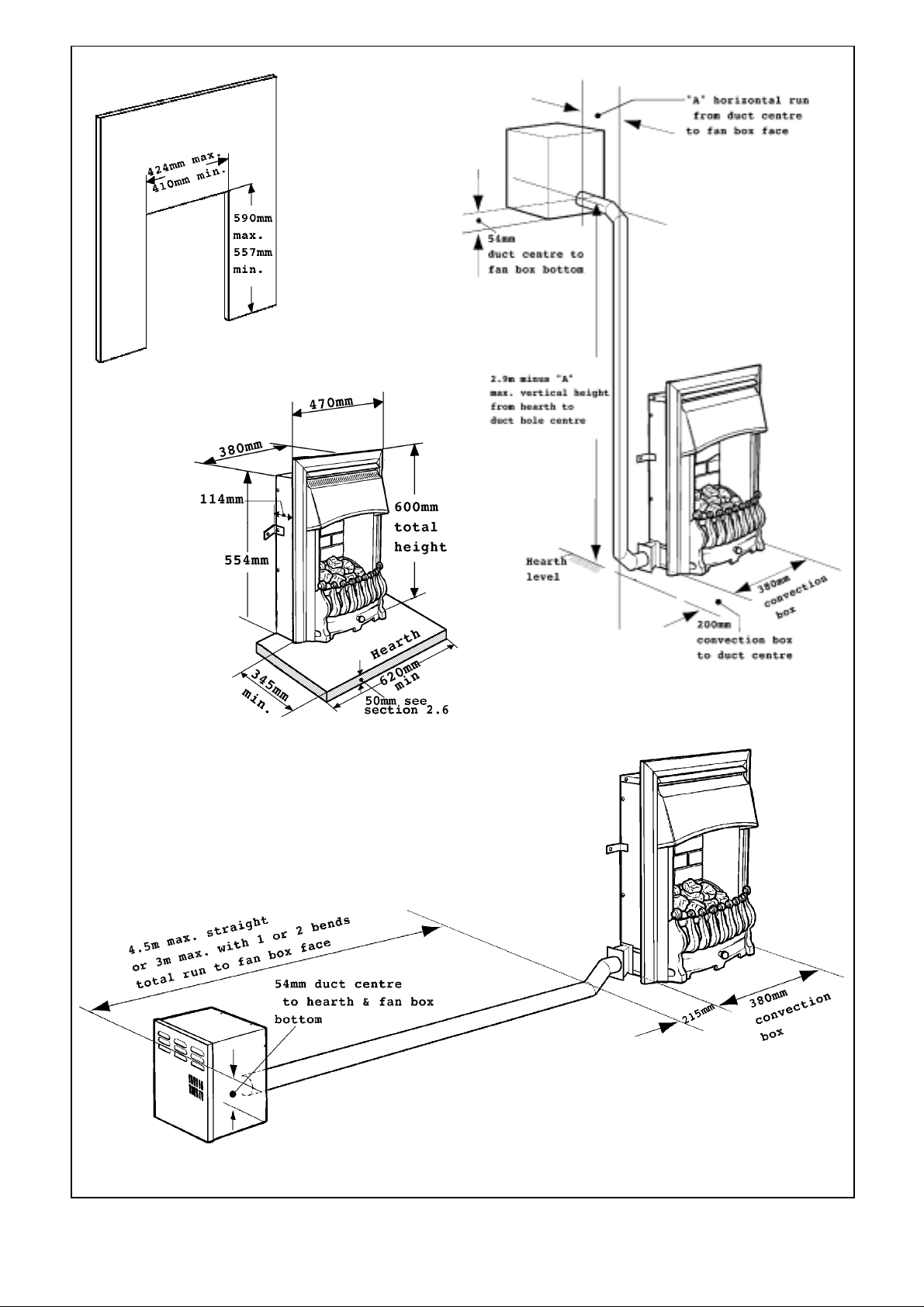
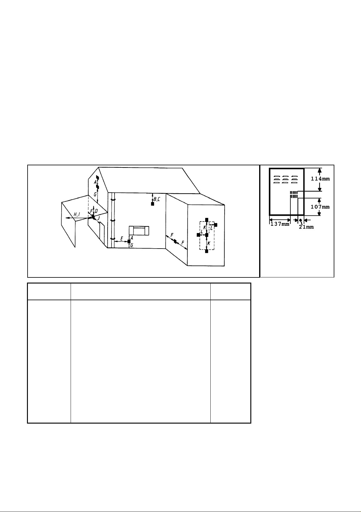
Surround Cut-out
Dimensions
Fig. 1 General installation dimensions
6

2.4 The appliance is suitable for the following flue duct arrangements:i. A st r a ight horizont a l run up to a maximum of 4.5m. For normal timber
frame buildin g s a straight r un will not be po ssib l e. See section 2.5.
ii. A horizontal run up to a max imum of 3m incl uding one or two b ends.
Minimum wall thickness 90mm.
iii. A vertical run up to a maximum of 3m (two bends are required for a
vertical installation). Minimum wall thickness 90mm.
The above run lengths are the total measurements from the rear of the fan box to the duct
connection at t he side of the appliance
The flue duct can be fitted to either side of the appliance.
Figure 1 shows the critical installation dimensions
2.4.1 The standard appliance is supplied with a total of 3m of straight ducting.
The following optional ex tra kits are available:
Kit No. 517IBK - Internal elbow bend ki t
Kit No. 517EBK - External e l b ow b end kit.
Kit No. 517 FDK - 1.5m extr a flue duct le ngt h with covers.
Kit No. 517DK - 1.5m extra flue duct length without covers.
2.5 This appliance is suitable for installation in conventional buildings
constructed of brick, stone etc. and in timber framed buildings.
2.5.1 Installation in timber framed buildings should be in accordance with the
relevant sections of The Institute of Gas Engineers publication IGE/UP/7 “Gas
installations in timber frame buildings”. Please note that advice should be sought
before installing in a timber frame building since the alterations required may
nullify any NHBC cover relating to the property. If in doubt, guidance should be
requested from your local authority planning o r building departme nt.
In timber fr amed insta llations a n annular non-combusti b le sleeve should b e
fitted around the flue tube where it passes through the combustible inner wall .
There should be a minimum 25mm air gap between the flue tube and the
sleeve. The gap shall be sealed to prevent the passage of air, heat and moisture.
The space between the flue ducts and the wall on which the appliance is
mounted is less than 25mm. Elbow bends will therefore be necessary to allow
the annular sleeve to clear of the wall on which the ap p liance is mounted.
2.6 This appl iance must be mounted wi t h a no n-co m b ust ible hea rt h (n.b
conglomera t e marble hearths are considered as non-combusti b le). The fire box
must be mounted on a non-combustible surface. The hearth must project at
least 345mm fo rwar d o f the convection box fr ont and be at least 620m m wide
(See figure 1). The hearth material must be at least 12mm thick. The periphery
of the hearth (or fender) should be at le ast 50mm above floor l e vel to discourage
the placing of carpets or rugs over it.
The surface of the hearth must be sufficiently flat to enable the bottom of the
front surround, the burner bracket and the bottom front cover casting to be
aligned horizonta lly. Any excessive unevenness (uneven til es, Cotswol d stone,
etc.) should be rectified.
The appliance must not stand on combustible materials or carpets.
7
2.7 The appliance must not be fitted directly against a combustible
wall. If the appliance i s to be fitted against a wall with combustible cladd i ng,
such materials must be removed from the area covered by the metal oute r
surround of the appliance (see figure 1). We suggest that the actual surround is
used as a template to mark the area for combustible cl ad d ing removal.
• The appli a nce can be fitte d t o a pur po se made propr ietary class “O ” 150° C
surround.
• The cut-out area in the surround should be between the size limits shown in
figure 1.
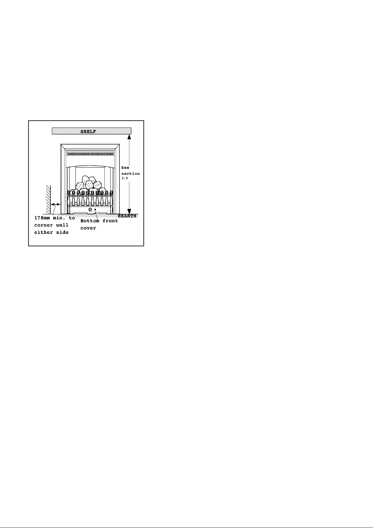
2.8 The minimum allowable distance from the outside edge of the
metal front surround of the appliance to a corner wall having
combustibl e materials is 178mm at e ither sid e (see figure 2).
2.9 The minimum height from the top surface of the hearth to the
underside of any shelf made from wood or other combustibl e
materials is as follows:-
• For a shelf up to 150mm deep
• Minimum height = 750mm .
• For a shelf deeper than 150mm
• Minimum height = 750m m + 12.5mm for every 25mm
depth over 150mm.
Fig. 2
2.10 Note that soft wall coverings (e.g. embossed vinyl, etc.) are
easily affected by heat. They may scorch or become discoloured
when close to a heating appliance. Please bear this in mind when
installing.
2.11 The appliance must not be installed in any room which contains a bath or
shower or where steam is regularly present.
2.12 An extractor fan may only be used in the same room as this appliance, or
in any area from which ventilation for the appliance is taken, if it does not affect
the safe performance of the appliance. Note the spillage test requirements
detailed further on in this manual. If the extractor fan is likely to affect the
appliance, the appliance must not be installed unless the fan is permanently
disconnected.
2.13 A fan-powered flue system t ends to de p ressurise t he room containi ng t he
appliance. In the United Kingdom no additional ventilation should normally be
required. In the Republic of Ireland permanent ventilation must comply with
the rules in force. In exceptional circumstances however, the spillage check (See
further on in this guide) may indicate a need for further ventilation in order to
ensure that there is adequate air replacement. If necessary seek expert advice.
2.14 Make sure th at the damp co urs e or a ny electr ical w iring , pipin g et c in t he
wall is not affected when cutting the flue box or spigot installation hole.
2.15 Any gas supply pipe installed in the wall, floor or cavity of a cavity wall
must be continuous and enclosed in a factory fitted gas tight sleeve (Ref: Gas
safety (Installation & Us e) Regulat ions 1994 as amende d & Certifi cat e of
exemp t ion no.1 1996).
8
2.16 Propane gas appliances must not be installed in a room which is built
entire ly below ground level ( s ee BS 5871 Part 2).
2.17 A concealed gas supply conne ct ion can be mad e through grommet near
the right corner of the rear panel. Visible front connection can be from the left
or right side.
2.18 Electrical connection to the isolating switched fused spur is from the left
side.
2.19 The flue terminal should be located so that the wind can blow freely
across it at all times and where any blockage due to leaves, snow, etc. is unlikely.
The minimum allowable distances from the terminal are shown in the
followi ng t ab le and figur e 3. Note: The dist ances are fro m the edge of the vertical exit
slots in the terminal not from the edges of the rectangular box (See figure 3a).
Fig. 3
Dimension Terminal Position Minimum
Distance
A Directly below an opening, air brick, windows,
300mm
etc.
B Below gutters, soil pipes or drain pipes 75mm
C Bel ow eaves 200mm
D Below balconies or car por t r oo f 200mm
E From a vertical drain pipe or soil pi pe 75mm
F From an internal o r external corne r 200mm
G Above ground, roof or b alcony leve l 300mm
H From a surface facing the t erminal 600mm
I From a terminal facing the terminal 1200mm
J From an opening in a car port (e.g. door,
1200mm
window) into dwelling
K Verticall y from a t erminal on the sa m e wall 1500mm
L Horizontally from a t erminal on the sa m e wall 300mm
M P roje cti on outwards from wall 50mm
Minimum distances for
terminal positions shown
in the table are from slot
openings
Fig. 3a
2.20 This appliance is suppl ied with a terminal guard . In England and Wales,
the Building Regulations require that the terminal guard is fitted if the flue
terminal can come in contact with people near the buildi ng or be subject to
damage. Even if the regulations do not demand it, we recommend that the
guard is fitted to prevent damage or blockage of the flue system by leaves etc.
9
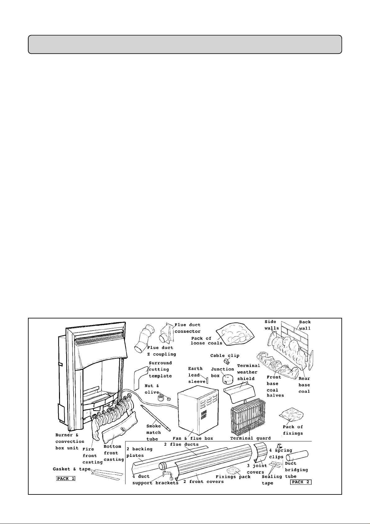
PART3: UNPACKING
This appliance is contained in two packs.
The fire front will be one of two alternatives: All black or black & brass finish.
The packs contain the following (see figure 4).
Pack 1 contains :
1 Burner & convection b ox unit
fitted with front surround*.
1 Fan & fl ue box unit (with wall
mounting brackets attached)*.
1Terminal guard.
1 Flue d uct connector unit &
gasket.
1 Flue duct Z coupling.
1 Nut & olive for 8mm inlet pipe.
1 Ceramic back wall.
1 Pair of ceramic side walls.
1 Front base coal left & right
halves.
1Rear base coal.
1 Pack of 5 loose coals.
1 Pipe bending template.
1 Surround cutting metal template.
1 Smoke match tube.
1 Terminal weather shield.
1 Junction box with cable clip,
earth lead sleeve & fixings.
Carefully remove the contents.
* The fan box unit and the convection box unit are linked by the fan supply
cable - Ta ke care w hen rem oving the un its fr oom th e carto n. Take sp ecial ca re
in han dling the cera mic walls and th e coals. Chec k that all the listed p arts are
present and in good condition.
1 Fire front casting.
1 Strip ga sket & sealing tape (For
surround insulation)
1 Bottom front cover casting.
6 Wood screws & pl ugs.
2 Stainless steel screws.
4 Self tapping screws.
1 Literature pack.
Pack 2 contains :
2 1.5m l ong flue ducts.
2 1.5m long duct backing plates.
2 1.5m long duct front covers.
4 Duct support brackets
4 Machine s cr ews & nuts
4 Spring clips (for cable).
3 Joint covers.
1 Duct bri dging tube
4 Woodscrews, plasti c washe rs &
wall plugs
2 Lengths sealing tape
Fig. 4 Pack contents
10
PART4:PREPARING APPLIANCE FOR INSTALLATION
4.1 Cut the fan cable
The applia nce is supplied w ith the fan supply ca ble linking the f an box to th e
convection box unit. To enable the fan unit to be installed to the wall, the cable
will hav e to be cut. A junctio n box is su pplied for rec onnectin g the c able af ter
installation of the fan unit and ducting. The junction box is intended to be fixed
to the wall at the side of the ap pliance. I t sho uld be pos itioned so that it will be
behind the fireplace surround.
Cut the cable at the point suitable for reconnecting to the junction box. This
will usually be just past the end of the grey abrasion resistant insulation sleeve.
!Always cut the cable before the mains cable is connected to the
electricity supply system
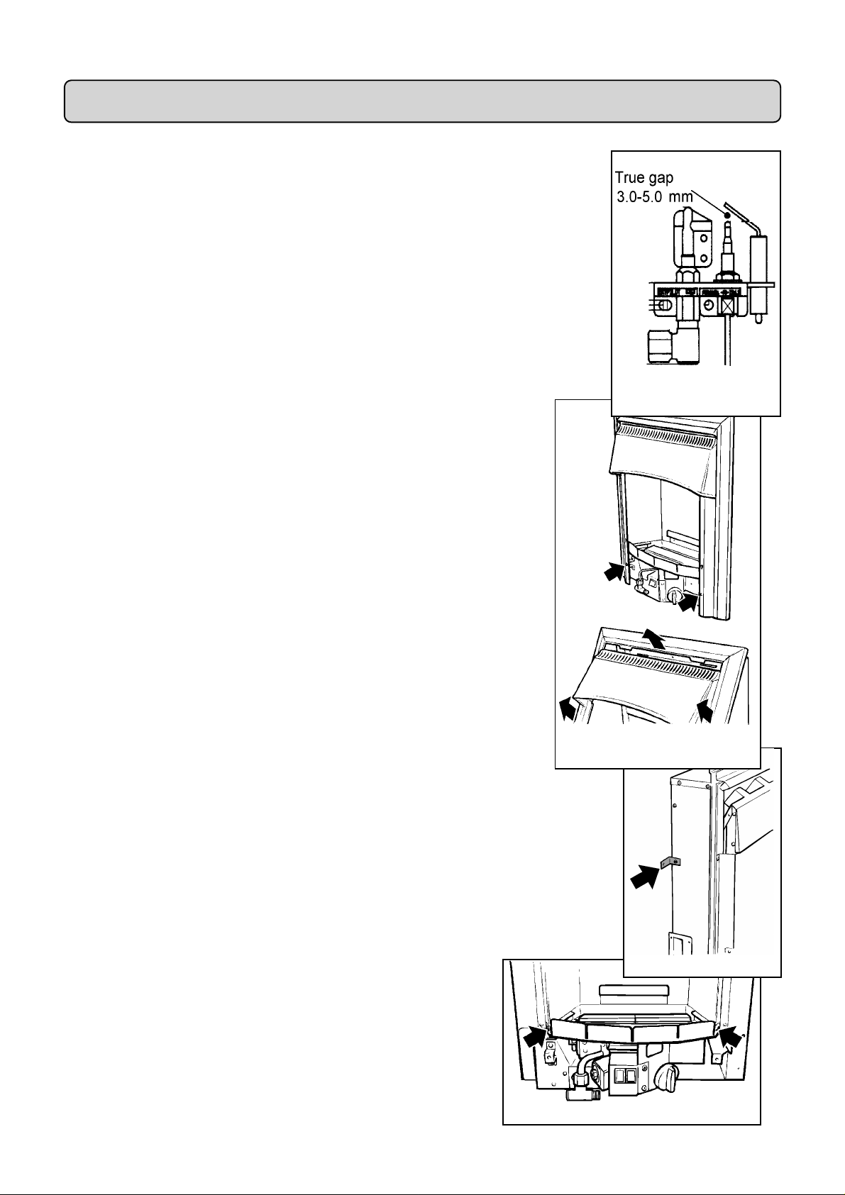
4.2 Check ignition spark
Before attempting to install, it is worth checking that the piezo electric
spark ignition system operates satisfactoril y.
To initiate the spark, depress the control knob and while keeping it
depressed, turn anticlockwise through approximately 60° to the
“PILOT/IGN” position. A spark should track from the electrode pin to
the thermocouple tip. If there is no spark or incorrect tracking, check the
spark gap between the electro de wire and th ermoco uple tip (s ee figu re 5).
If the spark gap is correct, check the ignition wi ri ng.
4.3 Remove the two screws securing the bottom of the front surround
to the sides of the convection box. Raise the front surround to allow the
retaining lugs at the top to clear the slots in the convection box hood and
then lift clear (see figure 6).
4.4 Detach the terminal guard and other fittings from the back of the
convection box by removing two screws and washers. The two scre ws are
for transit purposes only but the washers will be required to fit the guard to
the fan box outlet - Do not discard them.
4.5 For transit purposes the wall fixing brackets are fitte d to the
convection box facing inwards. Remove the brackets and refit them with
the long legs facing outwards (see figure 7).
Figure 5 Pilot Ignition
System
Figure 6 Front Surround
Removal
4.6 In the majority of cases temporary removal of mains cable will make
connection to the isolating switch easier. To allow this, the burner unit will
need to be detached. De tach the burner unit from the convection box by
removing two screws (see fi gure 8).
Figure 8 Burner Removal P oints
Figure 7
11
 Loading...