

Page 1
INSTALLER GUIDE
MODEL BR517S
(G.C.32-032-12)
ULTIMATE TURBOCHIM*
Side Fan Flued
Inset Gas Fire
*Covered b y GB Patent 2.202.622B
Please ke e p in a safe p l ac e for fut ur e r e fe r e n c e
600B313/02
Page 2

Please leave this Installer Guide with the user
As supplied, this appliance is for use with natural
gas (G20)
When converted using Valor conversion kit
no.591149 this appliance is for use with propane
gas (G31)
This appliance is for use in the United Kingdom
(GB) and the Republic of Ireland (IE) only.
CUSTOMER CARE
This Installer Guide gives sufficient details to enable the appliance to be installed
and maintained. If further information is required, our Valor AdviceLine will
be pleased to hel p.
Please telephone 0345 626341 (Local call rates apply)
2
Page 3

CONTENTS
Page
Appliance data 4
General in s tallation requiremen t s 5-9
Contents of packs 10
Preparing applian c e f o r installation 11
Electrical in s tallation 12
Gas supply & flue duct siting 13-14
Fan box ins t allation 15
Flue duct in stallation 16-19
Electrical tests 20
Terminal gu arding 21
Front surround & gas s upply inst allation 22-23
Ceramic coals & walls inst allat ion 24-25
Full operatin g c h e c ks 26-27
• Control settings check
• Spillage chec k
• Flame supervision & monitoring system check
Final review 28
Servicing & parts replacem ent 29-32
• Burner plaques replace ment
• Front surround rem o val
• Pilot unit removal
• Burner un it removal
• Gas tap, F.S.D. & solenoid removal
• Piezo ge n erator rem o val
• Main burner elbow injector removal
• Fan switch re moval
• Electrical control components access
• Distribution block removal
• Air press u re switch rem o val
• Fan removal
Short list of spares 33
26
26-27
27
29-30
30
30
30
31
31
31
31
31-32
32
32
32
3
Page 4
PART1: APPLIANCE DATA
This pro duct u ses fu el effect pieces. It makes sen se to ta ke care when ha ndling
these articles to ensure that the release of dust is kept to a minimum
This appliance do es not contain any co m p o nent manufacture d from asbes t os o r
asbestos related prod ucts.
The appliance data label and wiring diagram are on a tie below the burner and
are visible when the bottom front cover is removed.
Gas Natural (G20) Propane (G31)*
Inlet P ressure 20mbar 37mbar
Input - Max. (Gr os s ) 6.0kW (20,500B t u/h) 6.1kW (20,800B t u/h)
Input - Min. ( Gro s s) 2.2kW (7,500Btu/h) 3.6kW (12,280B t u/h)
Output - Max. 3.12kW (10,600B t u/h) 3.6kW (12,280B t u/h)
Output - Min 1.1kW (3,750Btu/h) 1.8kW (6,140Btu/h)
Burner Test Pressure
(Cold)
Gas Connection 8mm pipe 8mm pipe
Burner Inje ct or Bray Cat. 18 Size 360 Bray Cat. 18 Size 170
Pilot & Atmosphere
Sensing De vice
Ignition Piezo Electric. Integral
Aeration Non-adjustable Non-adjustable
Electrical supply 230V ~ 50Hz AC 230V ~ 50Hz AC
Fan motor rati ng 55W 55W
Fuse rating 3A 3A
18.2±0.75mbar
(7.3±0.3in w.g.)
SIT Ref. OP9044 SIT Ref. OPLPG9222
with Gas Tap
35.6±0.75mbar
(14.3±0.3in w.g.)
Piezo Electric. Integral
with Gas Tap
.
*When converted using kit 591149
4
Page 5

PART2:GENERAL INSTALLATION REQUIREMENTS
2.1 The installation must be in accordance with these instructions.
For the user’s protection, in the United Kingdom it is the law that all gas
appliances are installed by competent persons in accordance with the current
edition of the Gas Safety (Installation and Use) Regulations. Failure to install
the appliance correctly could lead to prosecution. The Council for the
Registration of Gas Installers (CORGI) re quires its members to work to
recognised standard s.
In the United Kingdom, all electrical supply installation must be installed in
accordance with t he cur rent edit ion of the IEE Wiring Regulations (BS7671).
In the United Kingdom the installation must also be in accordance with:
a) All the relevant parts of local regulations.
b) The current edition of the Building Regulations issued by the Department
of the Environment and the Welsh Office or the Building Standards
(Scotland) Regulations issued by the Scottish Development Departme nt.
c) All relevant codes of practice.
d) The relevant parts of the current editions of the following British
Standards:-
BS 5440 Part 1
BS 5871 Part 2
BS 6891
In the republic of Ireland the installation must also conform with:
a) The current editions of:-
IS 813
ICP3
IS327
b) All relevant national and local rules in force.
The current ETCI National Rules for Electrical Installation.
2.2 Electrical isolation of the unit should be by means of a switched fuse
spur that should be readily accessible to the user, easily identifiable and
preferably sited adjacent to the appliance. It should only connect this appliance.
2.3 This fire is a fan flued appliance. This appliance is designed for
installation in a room which does not have a purpose built flue or chimney and
where it is intend ed to be aga inst a wall where the fanned flue can not b e sited
direct ly behind t he heater.
5
Page 6
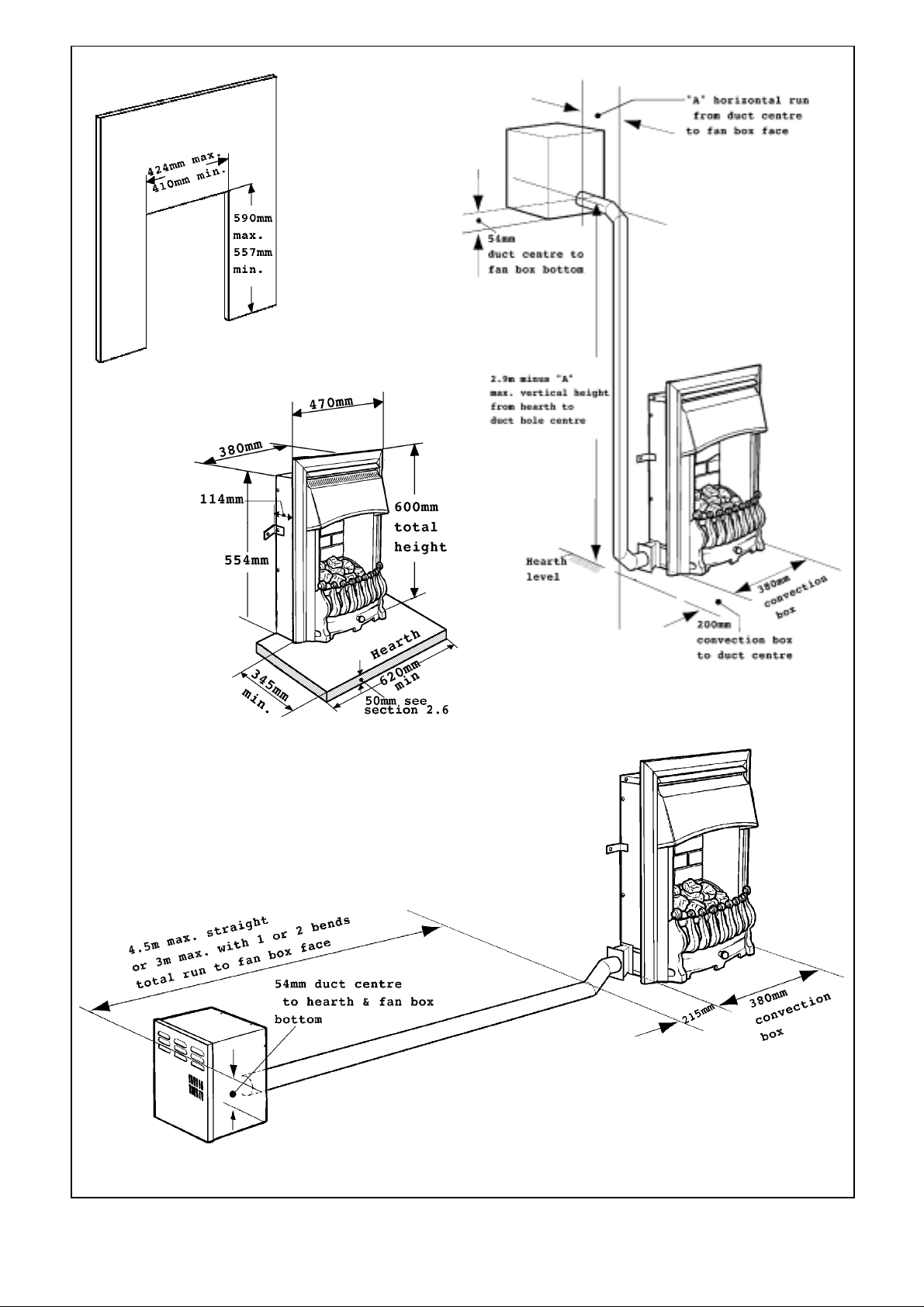
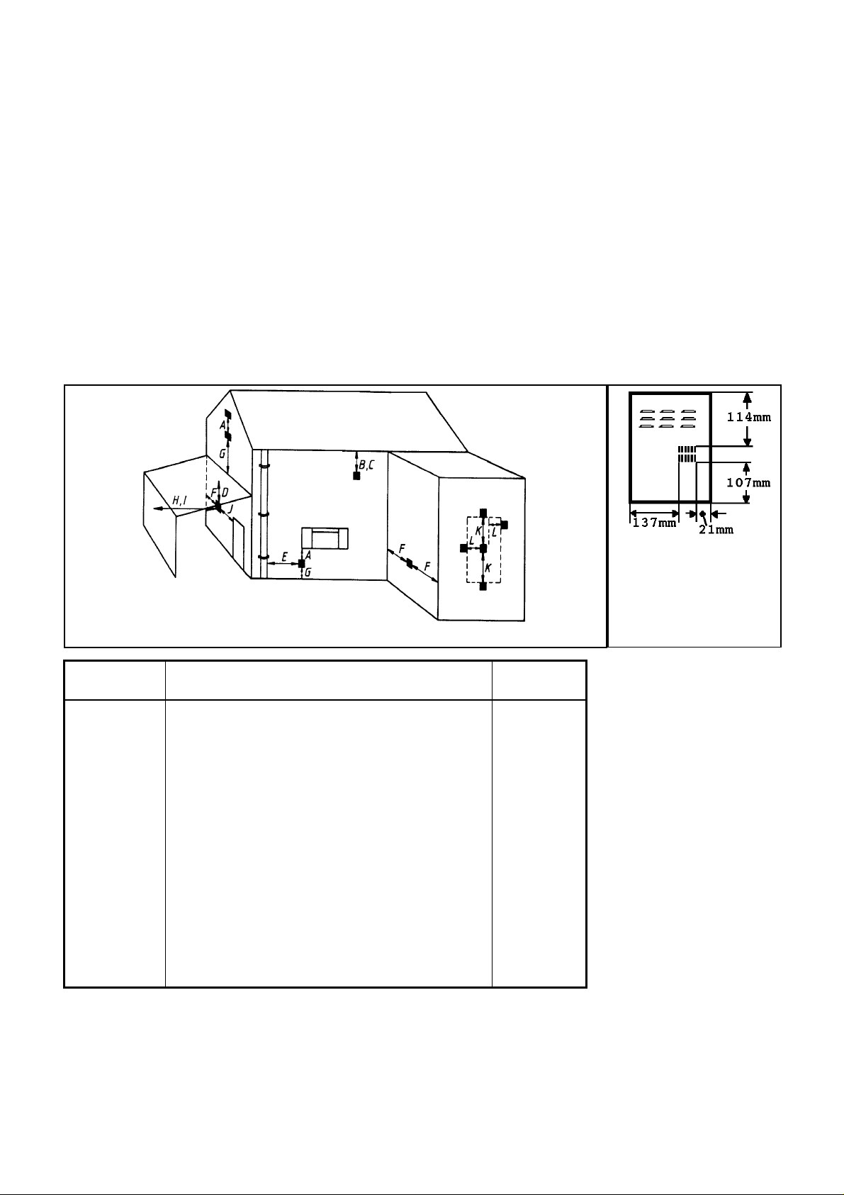
Surround Cut-out
Dimensions
Fig. 1 General installation dimensions
6
Page 7

2.4 The appliance is suitable for the following flue duct arrangements:i. A st r a ight horizont a l run up to a maximum of 4.5m. For normal timber
frame buildin g s a straight r un will not be po ssib l e. See section 2.5.
ii. A horizontal run up to a max imum of 3m incl uding one or two b ends.
Minimum wall thickness 90mm.
iii. A vertical run up to a maximum of 3m (two bends are required for a
vertical installation). Minimum wall thickness 90mm.
The above run lengths are the total measurements from the rear of the fan box to the duct
connection at t he side of the appliance
The flue duct can be fitted to either side of the appliance.
Figure 1 shows the critical installation dimensions
2.4.1 The standard appliance is supplied with a total of 3m of straight ducting.
The following optional ex tra kits are available:
Kit No. 517IBK - Internal elbow bend ki t
Kit No. 517EBK - External e l b ow b end kit.
Kit No. 517 FDK - 1.5m extr a flue duct le ngt h with covers.
Kit No. 517DK - 1.5m extra flue duct length without covers.
2.5 This appliance is suitable for installation in conventional buildings
constructed of brick, stone etc. and in timber framed buildings.
2.5.1 Installation in timber framed buildings should be in accordance with the
relevant sections of The Institute of Gas Engineers publication IGE/UP/7 “Gas
installations in timber frame buildings”. Please note that advice should be sought
before installing in a timber frame building since the alterations required may
nullify any NHBC cover relating to the property. If in doubt, guidance should be
requested from your local authority planning o r building departme nt.
In timber fr amed insta llations a n annular non-combusti b le sleeve should b e
fitted around the flue tube where it passes through the combustible inner wall .
There should be a minimum 25mm air gap between the flue tube and the
sleeve. The gap shall be sealed to prevent the passage of air, heat and moisture.
The space between the flue ducts and the wall on which the appliance is
mounted is less than 25mm. Elbow bends will therefore be necessary to allow
the annular sleeve to clear of the wall on which the ap p liance is mounted.
2.6 This appl iance must be mounted wi t h a no n-co m b ust ible hea rt h (n.b
conglomera t e marble hearths are considered as non-combusti b le). The fire box
must be mounted on a non-combustible surface. The hearth must project at
least 345mm fo rwar d o f the convection box fr ont and be at least 620m m wide
(See figure 1). The hearth material must be at least 12mm thick. The periphery
of the hearth (or fender) should be at le ast 50mm above floor l e vel to discourage
the placing of carpets or rugs over it.
The surface of the hearth must be sufficiently flat to enable the bottom of the
front surround, the burner bracket and the bottom front cover casting to be
aligned horizonta lly. Any excessive unevenness (uneven til es, Cotswol d stone,
etc.) should be rectified.
The appliance must not stand on combustible materials or carpets.
7
Page 8
2.7 The appliance must not be fitted directly against a combustible
wall. If the appliance i s to be fitted against a wall with combustible cladd i ng,
such materials must be removed from the area covered by the metal oute r
surround of the appliance (see figure 1). We suggest that the actual surround is
used as a template to mark the area for combustible cl ad d ing removal.
• The appli a nce can be fitte d t o a pur po se made propr ietary class “O ” 150° C
surround.
• The cut-out area in the surround should be between the size limits shown in
figure 1.
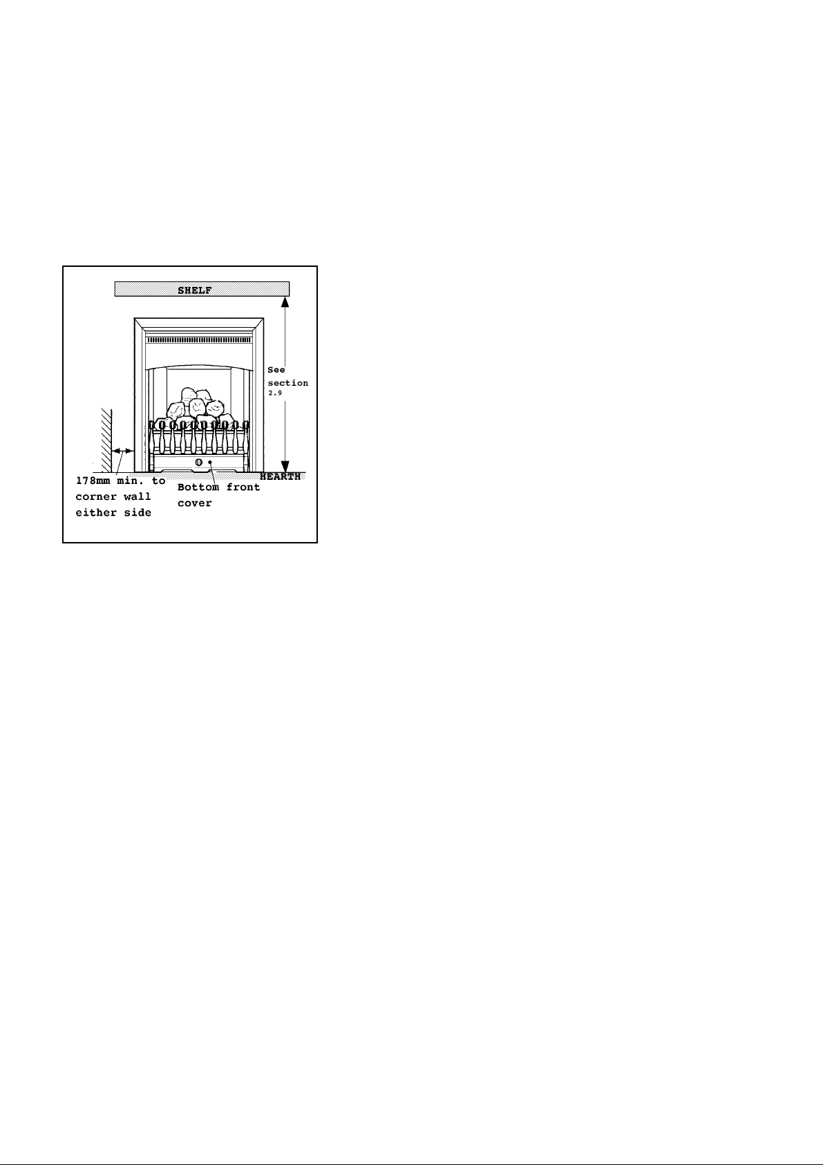
2.8 The minimum allowable distance from the outside edge of the
metal front surround of the appliance to a corner wall having
combustibl e materials is 178mm at e ither sid e (see figure 2).
2.9 The minimum height from the top surface of the hearth to the
underside of any shelf made from wood or other combustibl e
materials is as follows:-
• For a shelf up to 150mm deep
• Minimum height = 750mm .
• For a shelf deeper than 150mm
• Minimum height = 750m m + 12.5mm for every 25mm
depth over 150mm.
Fig. 2
2.10 Note that soft wall coverings (e.g. embossed vinyl, etc.) are
easily affected by heat. They may scorch or become discoloured
when close to a heating appliance. Please bear this in mind when
installing.
2.11 The appliance must not be installed in any room which contains a bath or
shower or where steam is regularly present.
2.12 An extractor fan may only be used in the same room as this appliance, or
in any area from which ventilation for the appliance is taken, if it does not affect
the safe performance of the appliance. Note the spillage test requirements
detailed further on in this manual. If the extractor fan is likely to affect the
appliance, the appliance must not be installed unless the fan is permanently
disconnected.
2.13 A fan-powered flue system t ends to de p ressurise t he room containi ng t he
appliance. In the United Kingdom no additional ventilation should normally be
required. In the Republic of Ireland permanent ventilation must comply with
the rules in force. In exceptional circumstances however, the spillage check (See
further on in this guide) may indicate a need for further ventilation in order to
ensure that there is adequate air replacement. If necessary seek expert advice.
2.14 Make sure th at the damp co urs e or a ny electr ical w iring , pipin g et c in t he
wall is not affected when cutting the flue box or spigot installation hole.
2.15 Any gas supply pipe installed in the wall, floor or cavity of a cavity wall
must be continuous and enclosed in a factory fitted gas tight sleeve (Ref: Gas
safety (Installation & Us e) Regulat ions 1994 as amende d & Certifi cat e of
exemp t ion no.1 1996).
8
Page 9
2.16 Propane gas appliances must not be installed in a room which is built
entire ly below ground level ( s ee BS 5871 Part 2).
2.17 A concealed gas supply conne ct ion can be mad e through grommet near
the right corner of the rear panel. Visible front connection can be from the left
or right side.
2.18 Electrical connection to the isolating switched fused spur is from the left
side.
2.19 The flue terminal should be located so that the wind can blow freely
across it at all times and where any blockage due to leaves, snow, etc. is unlikely.
The minimum allowable distances from the terminal are shown in the
followi ng t ab le and figur e 3. Note: The dist ances are fro m the edge of the vertical exit
slots in the terminal not from the edges of the rectangular box (See figure 3a).
Fig. 3
Dimension Terminal Position Minimum
Distance
A Directly below an opening, air brick, windows,
300mm
etc.
B Below gutters, soil pipes or drain pipes 75mm
C Bel ow eaves 200mm
D Below balconies or car por t r oo f 200mm
E From a vertical drain pipe or soil pi pe 75mm
F From an internal o r external corne r 200mm
G Above ground, roof or b alcony leve l 300mm
H From a surface facing the t erminal 600mm
I From a terminal facing the terminal 1200mm
J From an opening in a car port (e.g. door,
1200mm
window) into dwelling
K Verticall y from a t erminal on the sa m e wall 1500mm
L Horizontally from a t erminal on the sa m e wall 300mm
M P roje cti on outwards from wall 50mm
Minimum distances for
terminal positions shown
in the table are from slot
openings
Fig. 3a
2.20 This appliance is suppl ied with a terminal guard . In England and Wales,
the Building Regulations require that the terminal guard is fitted if the flue
terminal can come in contact with people near the buildi ng or be subject to
damage. Even if the regulations do not demand it, we recommend that the
guard is fitted to prevent damage or blockage of the flue system by leaves etc.
9
Page 10
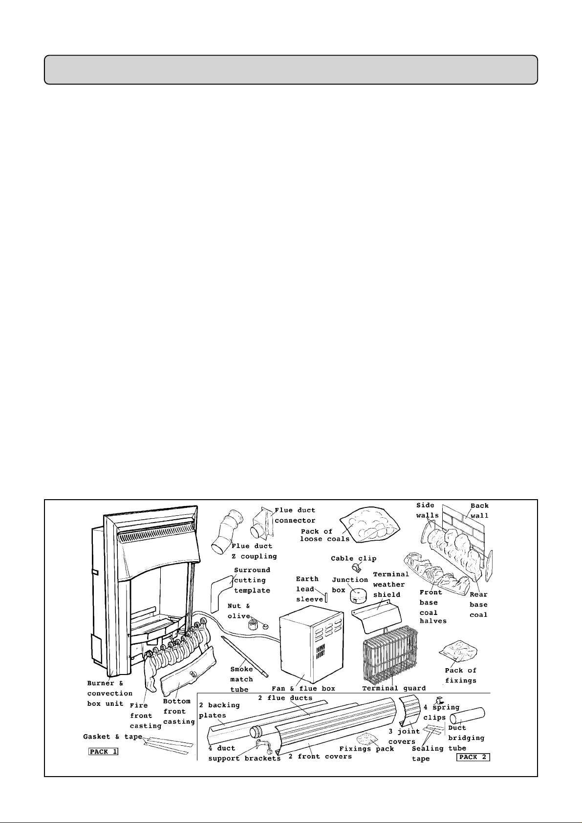
PART3: UNPACKING
This appliance is contained in two packs.
The fire front will be one of two alternatives: All black or black & brass finish.
The packs contain the following (see figure 4).
Pack 1 contains :
1 Burner & convection b ox unit
fitted with front surround*.
1 Fan & fl ue box unit (with wall
mounting brackets attached)*.
1Terminal guard.
1 Flue d uct connector unit &
gasket.
1 Flue duct Z coupling.
1 Nut & olive for 8mm inlet pipe.
1 Ceramic back wall.
1 Pair of ceramic side walls.
1 Front base coal left & right
halves.
1Rear base coal.
1 Pack of 5 loose coals.
1 Pipe bending template.
1 Surround cutting metal template.
1 Smoke match tube.
1 Terminal weather shield.
1 Junction box with cable clip,
earth lead sleeve & fixings.
Carefully remove the contents.
* The fan box unit and the convection box unit are linked by the fan supply
cable - Ta ke care w hen rem oving the un its fr oom th e carto n. Take sp ecial ca re
in han dling the cera mic walls and th e coals. Chec k that all the listed p arts are
present and in good condition.
1 Fire front casting.
1 Strip ga sket & sealing tape (For
surround insulation)
1 Bottom front cover casting.
6 Wood screws & pl ugs.
2 Stainless steel screws.
4 Self tapping screws.
1 Literature pack.
Pack 2 contains :
2 1.5m l ong flue ducts.
2 1.5m long duct backing plates.
2 1.5m long duct front covers.
4 Duct support brackets
4 Machine s cr ews & nuts
4 Spring clips (for cable).
3 Joint covers.
1 Duct bri dging tube
4 Woodscrews, plasti c washe rs &
wall plugs
2 Lengths sealing tape
Fig. 4 Pack contents
10
Page 11
PART4:PREPARING APPLIANCE FOR INSTALLATION
4.1 Cut the fan cable
The applia nce is supplied w ith the fan supply ca ble linking the f an box to th e
convection box unit. To enable the fan unit to be installed to the wall, the cable
will hav e to be cut. A junctio n box is su pplied for rec onnectin g the c able af ter
installation of the fan unit and ducting. The junction box is intended to be fixed
to the wall at the side of the ap pliance. I t sho uld be pos itioned so that it will be
behind the fireplace surround.
Cut the cable at the point suitable for reconnecting to the junction box. This
will usually be just past the end of the grey abrasion resistant insulation sleeve.
!Always cut the cable before the mains cable is connected to the
electricity supply system
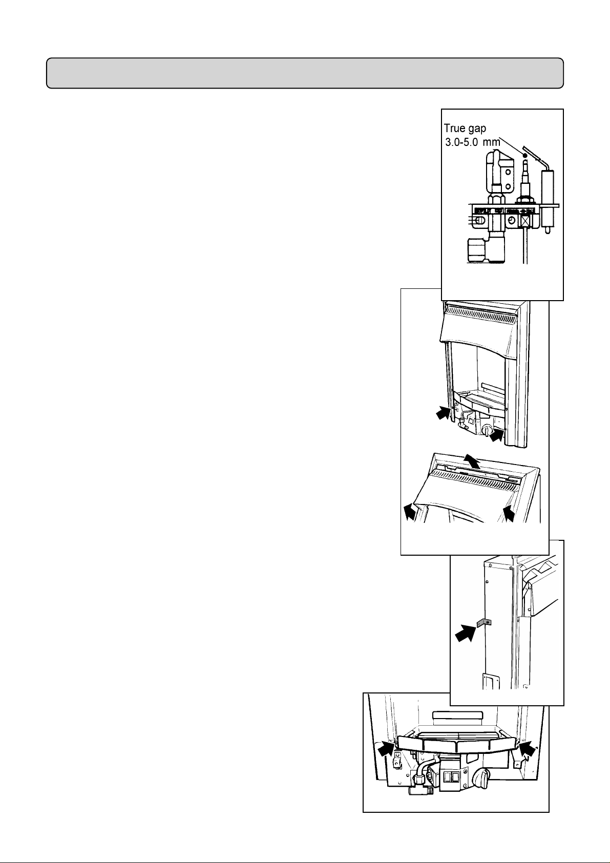
4.2 Check ignition spark
Before attempting to install, it is worth checking that the piezo electric
spark ignition system operates satisfactoril y.
To initiate the spark, depress the control knob and while keeping it
depressed, turn anticlockwise through approximately 60° to the
“PILOT/IGN” position. A spark should track from the electrode pin to
the thermocouple tip. If there is no spark or incorrect tracking, check the
spark gap between the electro de wire and th ermoco uple tip (s ee figu re 5).
If the spark gap is correct, check the ignition wi ri ng.
4.3 Remove the two screws securing the bottom of the front surround
to the sides of the convection box. Raise the front surround to allow the
retaining lugs at the top to clear the slots in the convection box hood and
then lift clear (see figure 6).
4.4 Detach the terminal guard and other fittings from the back of the
convection box by removing two screws and washers. The two scre ws are
for transit purposes only but the washers will be required to fit the guard to
the fan box outlet - Do not discard them.
4.5 For transit purposes the wall fixing brackets are fitte d to the
convection box facing inwards. Remove the brackets and refit them with
the long legs facing outwards (see figure 7).
Figure 5 Pilot Ignition
System
Figure 6 Front Surround
Removal
4.6 In the majority of cases temporary removal of mains cable will make
connection to the isolating switch easier. To allow this, the burner unit will
need to be detached. De tach the burner unit from the convection box by
removing two screws (see fi gure 8).
Figure 8 Burner Removal P oints
Figure 7
11
Page 12

PART5:ELECTRICAL INSTALLATION
Figure 9 Electrical control
unit fixings
5.1 Install a power supply at a switched fuse having a minimum separation of
3mm at all poles. The spur should be readily accessible to the user, easily
identifiable and preferably sited adjacent to the appliance. It should only connect
this appliance.
5.2 To simplify installation of the cable supplied, it may be most convenient
to disconnect it from the appliance as described below, install it to the wall and
then reconnect to the appliance:
To disconnect the cable:
1) Detach the burner (See section 4.5).
2) Detach the control unit from the convection box left side flange by
removing two screws (see figure 9). Carefully pull the unit slightly
forward.
3) De tach the control unit cove r by removi ng one scre w ( Se e figure 10).
4) Remove the cable by releasing the cable clamp and detaching the
leads from the termi nal block and earth contact tag.
5.3 When installing the cable, leave a minimum of 200mm of the
cable slac k at th e cable c lamp end t o allow installa tion of the applian ce
after reconnection to the control box and to allow future removal of the
control box for servicing.
Figure 10 Control cover fix i ng
!WARNING: Do not switch on the power supply until after the
fan cable h as b een corre ctly connected to the jun ction box - Se e
part 8.
5.4 If the spur is at the right side of the appliance, run the cable
under the hearth. The cable m us t n ot run direc t l y under or be h i n d t h e
appliance.
12
Page 13

PART6:GAS SUPPLY & FLUE SITING
6.1 If the gas supply pipe is to enter through the concealed rear opening,
pierce the grommet. If the supply pipe is sleeved, trim the sleeve back where it
enters the appliance and seal the sleeve to the pipe.
If the supply pipe is to run from the side of the appliance and enter through the
concealed rear opening, the wall will usually have to be chased to accommodate
the pipe at the back of the heater.
6.2 An installation template is supplied which includes a diagram for forming
the pipe so that it avoids various components below the burner.
6.3 This appliance is designed for installati on with a 114mm. (4.5in.) deep
fire surround or false chimney breast. For horiz ontal duct installations
the skirting board will have to be removed from behind the hearth and
along the total length of the flue duct run. If the skirting is not removed
the depth of the fire surround will need to be increased accordingly.
6.4 Place the hearth in its proper location. Place the appliance on the
hearth in its proper location. Mark the position of the wall fix i ng
brackets. Note: If a surround deeper than 114mm is to be installed, spacers will
be needed behind the wall mo unt ing brackets.
Figure 12
6.5 Remove the appliance. Drill holes at the marked positions using a
no.10 drill and plug.
6.6 For duct connection from t he right side:
6.6.1 Remove the flue aperture cover and gasket and fit them to the le ft sid e
(see figure 11). Be careful not to damage the gasket.
6.6.2 Remove the fan cable clamp from the rear left of the convection box.
Replace the screw thus removed into the convection box. Cl amp the cabl e
at one of the screws at the right side of the box (see figure 12).
6.7 Fit the flue duct connector to the open side of the convection box
with four tappi ng s cr ews. The narro w edge of the connecting plate must be
at the back (see figure 13).
Figure 11
Figure 13
6.8 Place the appliance back in position. Secure it to the wall through the
two side brackets using two woodscrews provided.
6.9 For horizontal duct installations: Fit the “Z” shaped duct coupling to
the duct connector pushing firmly to ensure a good seal. Rotate the
coupling so that its open end is as low as possible (see figure 14).
6.10 For vertical duct installati ons: Fit an elbow bend duct to the duct
connector pushing firmly to ensure a good seal. (see figure 15).
6.11 Mark the wall at the centre line of the flue duct (54mm above the hearth
for horizontal installations, 200mm from the side of the convection box for
vertical installations). Draw a line at this position along the wall from the heater
to where the fan box hole will be drilled.
13
Figure 14
Figure 15
Page 14

Figure 16
6.12 Drill the flue hole through the wall. The hole centre should be
on the flue duct centre line. For buildings constructed of brick, stone
etc use a 3½in. (89mm) core drill.
For timber framed buildings a sleeved 25mm gap is required between
the flue duct and the combustible leaf. For horizontal installations,
elbow ducts will be required to keep the gap clear of the wall on
which the appliance is mounted (see section 2.5.1). Drill a 5in
(127mm) dia. hole. The interior surface of the wall where the ho le is
expose d must be finished with non-co m b ust ible mat erials.
6.13 If it is intended to rece ss the fan box i nto the outer wall , make a
rectangular opening as shown in figure 16. The d epth of the recess is
145mm leaving the 50mm mi nimum projec t ion required outsid e the
wall.
Note that the fan box is not designed to be recessed into a timber framed
building.
14
Page 15

PART7:FAN BOX INSTALLATION
7.1 For transit purposes the fan mounting brackets are supplied fitted to
the fan box facing inwards. Remove them and refi t a s described belo w.
7.2 If the fan box is to be sited totally outside the wall fit the brackets with
the short flanges flush with the air intake end of the fan box (see figure 17).
7.3 If the fan box is to be recessed into the wall fi t the bracke ts with the
short legs 50mm from the air outlet face of the fan box (see figure 18).
7.4 Place the fan box in position with the duct connection spigot in the
hole in the wall and, if applicable, the fan box in the recess. Push the box
in so that the fixing brackets are against the wall and mark the screw
fixing positions on the wall.
7.5 Remove the fan box. Drill the marked positions using a no.10 drill
and plug the holes.
7.6 Push the fan cable through the hole in the wall into the room.
Figure 17 For box totally outside wall
7.7 Replace the fan box in position on the wall. Make sure when
inserting the duct connection spigot that its end does not cut into the
cable.
Figure 18 For box recessed in wall
7.8 Secure the fan box to the wall with the wood screws supplied.
7.9 Make good around the flue box ensuring that there are no gaps between
the fan box and wall.
15
Page 16

Figure 19
Figure 20
PART8:FLUE DUCTING INSTALLATION
8.1 The fireplace surround will have to be cut away at the side where the duct
connects to the appliance. A template is supplied to aid accurate cutting. It will
be simpler if the sid e is cut before assembling the top to the sides. P l ace the
template against the surround side as shown in figure 19. Mark the shape of the
opening on the surround. Cut the opening .
8.2 Cut the backing plates to length. Note that the appliance end of the backing
plate should a b ut against the o ut side face of the fireplace surround side. It does not go inside
the surround.
For corner installations the ends of the plates must be mitred and butted
together even when covered by the elbow front covers. Small children
could touch the hot ducting if there are any gaps between the top horizontal
flanges or bottom angled flange s of t he backing plate s .
8.3 Measure the length of the duct run between the intersection of the
horizontal and sloping sections of the “Z” coupling (“A” in fig. 20), fan box
spigot and, if applicable, elbows. The ducts must run from within 10mm of
the intersection”A” and enter the fan box spigot or elbow by a minimum of
40mm and a maximum of 70mm.
A bridging tube is supplied to aid manipulation of the ducts while installing.
The swaged end of one duct (the end with the seal) can be cut to allow a
gap of up to 125mm to b e bridge d (see figure 21).
Cut the ducts to suit the installation.
Figure 21
16
Page 17

8.4 Align the backing plates so that the centres of the fixing holes are at the
height of the duct centre line drawn on the wall (see section 6.11). Mark the
wall through two of the slotted holes in each backing plate. Usually the best
fixing positions will be those which are closest to the ends of the backing
plates.,
8.5 Remove the backing plates. Drill the wall at the marked positions using
a no. 10 drill. Fit the wall plugs supplied.
8.6 Fit two plastic duct support brackets to each backing plate through
the round holes with the machine screws and nuts supplie d. The screw
heads must be on the outside (back) face of the backing plates (see figure
22).
The brackets should be fitted so that they will support the ducts as near as
practical to the ends of the ducts. Note, however
• The brackets will not go over the swaged ends of the ducts.
• The brackets will not go over the bridging tube.
• The bottom angled edges of the backing plates should not catch in the
cable clip slots in the brackets.
8.7 Fix the backing plates to the wall. The plastic spacing washers must be
fitted between the backing plate s and the wal l . Fit using the wood screws
provided (see figure.23).
8.8 Place the flue ducts in positi on. Fit the bridging tube over one of
the ducts. Locate the ducts to the “Z” coupling, flue box and, if
applicable, e l bows. The flue ducts snap into the plastic support brackets
(see figure 24).
If the alignment of the backing plates and ducts is not quite right, remove
the ducts, slacken the screws holding the backing plates to the wall and
realign them. Refit the d ucts.
Figure 22
Figure 23
Figure 24
8.9 Slide the bridging tube so that it overlaps each duct by a minimum
of 50mm. Seal each end of the bridging tube to the ducts with the tape
supplied (see figure 21) .
8.10 Fit the fan cable into the “C” sections at the bottom of the support
brackets (see figure 25).
8.11 Further support for the fan cable (especially at corners) can be
provided using the spring cable clips supplied in the pack. Fit the clips to
the bottom edge of the backing plates and attach the cable (see figure 26).
Figure 25
Figure 26
17
Page 18

Figure 27
Figure 28
8.12 Select a suitable location for the fan cable junction
box. Fit the box and connect the cables as follows (see
figure 27):
8.12.1Remove the screw from the centre of the junction
box. Remove the co ver.
8.12.2Place the junction box in position. Mark the wall
through the two holes in the box.
8.12.3Drill the wall and fit the wall plugs supplied.
8.12.4Fix the junction box to the wall with the two
screws provided.
8.12.5If necessary shorten the cable attached to the fan
box to a suitable length so that it does not need to be coiled up.
8.12.6Strip the ends of the wires. Cut the earth lead sleeve (yellow &
green) into two pieces so that they will cover the exposed ends of the
earth wires. Slide a length over the bare earth wire in each cable.
8.12.7Connect the leads to the junction box as shown in figure 27.
Ensure that the colours of the leads in the fan cable connect with the
matching colours in the appliance cable.
8.12.8Fit the cable clip over both cables as shown in figure 27. Place the
clip in position against the wall. Mark the wall through the fixing hole.
Move the cables and clip out of the way. Drill and plug the wall. Replace the
clip. Screw the clip to the wall maki ng sure that the two cables are firmly
clamped. Refit the junction box cover.
Figure 29
8.13 When installed in a fire surround made of wood or other “combustible”
material, the ducting must be insulate d from the surround where it passe s
through the aperture in surround side. Wrap the insulating gasket round the
duct and secure with the seali ng tape suppl ied as shown in figure 28.
8.14 For horizontal duct installations:
8.14.1Size and cut the duct front covers and, if applicable, the elbow front
covers. Note that the appliance end of the duct front cover should abut against the outside
face of t h e fireplace surr ound side. It does not go inside the sur round.
8.14.2Secure the covers in front of the ducts by springing them over the
location channels in the support brackets (see figure 29).
8.14.3Where applicable, snap fit the joi nt covers over the joints be twe e n the
duct covers and snap fit elbow covers at the corners.
8.15 For vertical duct installations:
Normally a false chimney breast will be constructed to hide the ducting. The
duct front covers will not, therefore, be required for these installations, but
there must be at least 25mm space between the duct pipes and any combustible
surfaces. If, however, the ducting will be visible, fit the front covers as described
for horizontal installations (section 8.14).
8.16 Install the fireplace surround or complete the false chimney breast.
Important: The appliance must not be left with the customer in a condition where
it can be turned on unless the hearth and surround (or false chimney breast) are
completely installed.
8.17 The backing plates, front covers and joint covers can all be painted to suit
the room decor with any of the widely available primer and finishing paints
suitable for coating metal surfaces.
18
Page 19

8.18 Do not block the gap between the top horizontal flange of the
duct backing plates and the top rear edge of the front covers (see
figure 30).
Figure 30
19
Page 20

Fi
g
ure 31 Wiring diagram
PART9:ELECTRICAL TEST
9. 1 Switch on power supply. The red indicator light at the left side of the
burner should be on .
9.2 Press and hold in the “on” switch.
Within two seconds, the Fan motor should
start and the indicator light should go out.
9.3 Release the “on” switch. The fan
should continue to run.
9.4 Press the “off” switch. The fan should
stop and the indicator light should come on.
9.5 The fan has a “boost” speed intended
to clear any minor exhaust obstructions. To
check its operation:
i. Switch the fan on (9.1 to 9.3 above).
ii. Go outside the building and place a hand
over the rectangular exhaust outlet of the
terminal. The fan should be heard to i ncrease to “boost”
speed within approxi mately two seconds.
iii. Remove the hand. The fan should revert to normal speed
after approximately three se cond s.
Figure 32 Controls
9.6 The unit includes a b locked fl ue sensor system. To
check its operation:
i. Switch the fan on (9.1 to 9.3 above).
ii. Block off the rectangular exhaust outlet of the terminal.
The system should shut down and the indicator should
light within ten seconds.
iii. After checking remove the flue blockage .
If the above tests are not satisfactory, refer to the servicing section of this
manual.
Note: At tim es of very windy weather or low volt a ge conditions the fan may switch between
boost and normal speeds. A click from the atmospheric pressure sensor may be heard as the
fan switch es sp eeds.
20
Page 21

`````
PART10:TERMINAL GUARDING
Fit the weather shield and guard to the back of the flue unit as d etailed
below (s ee figures 33 & 34).
10.1 Remove the two screws near the sides of the terminal end just
below the louvres. Remove the screw near the bottom of the terminal
end.
10.2 Place the weather shield in position aligning the holes in the
shield with those at the sides of the e nd pl ate. Secure with the two
screws previously removed. see figure 33.
10.3 Fit the terminal guard (see fi gure 34). Se cure the guard at
the bottom and at the top between the two right hand columns of
louvres using screws included in the fixings pack and the washers
which were holding the guard to the convection box for transit
(see section 4.3) .
Figure 33 Weather Shi eld
Installation
Figure 34 Te rm i nal Guard Installation
21
Page 22

PART11:FRONT SURROUND & GAS SUPPLY
INSTALLATION
11.1 Locate the two lugs at the top of the front surround in the slots in the
convection box hood. Swing the bottom of the surround sides back against the
convection box and lower the surround so that the lugs are fully seated in the
slots in the convection box hood.
11.2 Refit the two screws to secure the surround sides to the convection box
brackets
11.3 Connect the supply line to the appliance.
Unless the supply pipe connection is from the left front side , the suppl y pipe
will have to be formed to avoid various components below the burner. An
installation template is supplied which contains a diagram for bending this
supply pipe.
11.4 Pressure check the installation pipework for gas soundness in accordance
with the current edition of BS6891. Do not use leak de te ctio n sprays o n this
appliance. Sprays may affect the operation of electrical components. Keep all liquid
detection fluids clear of electrical components. A long brush may be r equired to
reach some joints.
.
11.5 Preliminary Burner Checks
Some burner operations can be checked at this stage. Checking now will mean
that less disassembly will be required if any problems are found. A full check
should still be made, however, after final installation
11.5.1 Switch on electrical power supply. The red indicator light at the left side
of the burner should be on.
11.5.2If closed, open the isolating valve at the inlet elbow.
11.5.3 Press and hold in the “on” switch. Within two seconds, the Fan motor
should start and the indicator light should go out.
11.5.4 Release t he “on” swit ch. The fan shoul d continue to r un.
11.5.5 Depress the control knob and turn anticlockwise partially towards the
“PILOT/IGN” position until some resistance i s fe l t. Ke e p d e pressed at this
position to purge air from the system then, while keeping it depressed, turn
fully to the “PILOT/IGN” position. A spark should be generated at the pi l ot
while turning. The spark should ignite the pilot.
11.5.6 When pilot ignition has been achieved, keep the control knob depressed
for approximately ten seconds to allow the thermocouple probe to warm up and
then release it. If the pilot does not remain alight, ensure that the air has been
purged, that the pilot orifice is clear and that the thermocouple connections are
sound. Replace the pilot unit if necessary (see servicing section of this manual).
11.5.7 When the pilot is alight and stable, partially depress the knob and turn to
“LOW”. The pilot should then light the main burner at its low setting. There
may be a delay of up to four seconds between the pilot lighting and ignition of
the gas at the main burner. This is normal and is due to the time required to fill
the main burner compartment with sufficient gas for ignition.
11.5.8 With the burner at “LOW”, partially depress the control knob and
gradually turn it anti-clockwise. The burner flames should gradually increase
until the knob reaches the “HIGH” position. When the above checks have been
completed partially depress the control knob and turn to “OFF”.
.
22
Page 23

11.5.9Press the “off” switch. The fan should stop and the indicator light should
come on.
11.5.10If the above checks are satisfactory, continue with the installation. If not,
check the control and ignition circuitry and components as described i n the
servicing section of this manual.
11.6 Check Reference Pressure.
The appliance is pre-set to give the correct heat input at the inlet
pressure shown in part 1 of this manual. No adjustment is necessary.
Check the burner pressure by fitting a pressure gauge at the test point.
The test point is on the pipe si tuated be low the bottom right corner of
the burner unit (See figure 35). Check the pressure with the fan on,
the appliance alight and set at maximum output.
After checking, turn off the appliance. Remove the pressure gauge and
replace the test point seal i ng screw. Relight the appliance. Turn to the
maximum output position and test around the sealing screw for gas
Figure 35 Pressure test point
soundness with a suitabl e leak d etection fluid. Do not use le ak de te ctio n
sprays on this appliance. Sprays may affect the operation of electrical
components. Keep all liquid detection fluids clear of electrical components.
23
Page 24

PART12:CERAMIC COALS & WALLS INSTALLATION
12.1 With its feather
edge at the top, place
the ceramic rear wal l
into the channel at the
back of the fire box.
Push the wall flat
against the rear of the
fire box. (See figure
.
36)
12.2 Place the
two halves of the
front base coal in
the burner
compartment so
that they rest on
the ledges at the
sides and front.
Pull the coals
forward so that
they are
immediately
behind the front
rim of the burner
compartment (See
fig. 37).
12.3 Place the
rear base coal in the
burner compartment
behind the front coal.
Its rear face should
touch the rear ceramic
wall (See figure 38).
Fig. 36 Ceramic rear wall
installation
Fig. 37 Front coal installation
12.4 The ceramic
side walls are marked
at the rear
bottom corners “L”
(Left side) & “R”
(Right side). Place the
side walls agai nst the
sides of the fire box
and in the recesses at
the sides of the base
coals. The marki ngs
“L” & “R” should be
at the back bottom
corners and facing to
the centre of the
back of the firebox
(See figure 39)
.
12.5 Install the 5
loose coals as
follows. The
smooth surfaces of
the coals should be
at the bottom and
back.
12.5.1Select the
two largest coals.
Place them in the
central two valleys
of the front coal
(See figure 40).
12.5.2Place the
three remaining coals
behind and
approximately
midway between each
of the coals in the
front row (See figure
41).
Fig. 39 Cerami c s i d e walls
installation
Fig. 40 Front row inner coals
Fig. 38 Rear bas e coal
installation
24
Fig 41 Middl e row of c oals
Page 25

PART13:FULL OPERATING CHECKS
13.1 Recheck Cont r o l Settings
Now that all the ceramic fuel effects are in position, the control operation must
be fully rechecked.
13.1.1Make sure that the isolating valve at the inlet elbow is open and that the
electrical power supply is on (the indicator light should glow).
13.1.2Press and hold in the “on” switch. Within two seconds, the Fan motor
should start and the indicator light should go out.
13.1.3Release the “on” switch. The fan should cont inue to run.
13.1.4Depress the control knob and turn anticlockwise partiall y towards the
“PILOT/IGN” position until some resistance i s fe l t. Ke e p d e pressed at this
position to purge air from the system then, while keeping it depressed, turn
fully to the “PILOT/IGN” position. A spark should be generated at the pi l ot
while turning. The spark should ignite the pilot. Check that the pilot flame is
visible - See sect ion 12.5.3.
13.1.5When pilot ignition has been achieved, keep the control knob depressed
for approximately ten seconds to allow the thermocouple probe to warm up and
then release it. If the pilot does not remain alight, ensure that the pilot orifice is
clear.
13.1.6When the pilot is alight and stable, partially depress the knob and turn to
“LOW”. The pilot should then light the main burner at its low setting. There
may be a delay of up to four seconds between the pilot lighting and ignition of
the gas at the main burner. This is normal and is due to the time required to fill
the main burner compartment with sufficient gas for ignition.
13.1.7When the burner is operating properly, partially depress the knob and
gradually turn it anti-clockwise. The burner flames should gradually increase
until the knob reaches the “HIGH” position.
13.1.8Partially depress the control knob and turn back to “PILOT/IGN”. The
main burner flames should be extinguished but the pilot should remain alight.
13.1.9Partially depress the control knob and turn to “OFF”. The pilot should be
extinguished
13.1.10Press the “off” switch to turn off the fan (the indicator light should
glow).
.
25
Page 26

Figure 42 Smoke match tube
position
13.2 Check For Spillage
A spillage check must be made before leaving the installed appliance with the
customer. Make this check with the appliance fully installed with the ceramic fuel
effects and front surround in position.
13.2.1 Close all doors and windows in the room containi ng the appl i ance .
13.2.2 Turn on the fan. Light the appliance. Turn the control to “HIGH”.
13.2.3 Leave the appliance on for five minutes
.
13.2.4 Place the smoke match tube into the convection box at the right
hand side and immediately below the black top cross member. Angle it at
approximately 45° to the horizontal(fig. 42).
Insert the tube so that the neck of its flared end touches the insid e surface
of the edge of the cross member (figure 42).
Keeping the neck of flared end in contact with the edge of the cross
member, slide the tube to the l e ft until you feel it e nter the notch in the
edge of the cross member. Make sure that the tube is pointed upwards at
45º to the horizontal.
The installation is satisfactory if the smoke is drawn into the appliance. If
the smoke is not drawn into the appliance the powered fan is not operating
correctly. Do not allow the appliance to be used until the fault is corrected.
13.2.5 If the above test is satisfactory, open all internal connecting doors,
hatches, etc. in the room. Swi tch on any extractor fan or other air circulating
system installed in the same room as the appliance or in a connecting room.
Keep all doors and wi nd ows that open to the outsi d e of the building closed .
Recheck for spillage as above.
If the smoke is drawn into the appliance, continue with the install ati on. If the
test is not satisfactory, Disconnect the appliance and advise the customer of the
cause of fai lure.
13.2.6If any other non-sealed gas appliances are installed in the room or
connecting rooms, check that to ensure that there is no spillage from these
appliance s when Model B R517 is operat ing with its fan on. Check these ot her
appliances by the procedure supplie d by the manufacturer.
13.3 Flame Supervision & Spillage Monitoring System
This pilot unit incorporates a system which will automatically shut off the gas
supply if the pilot flame goes out or if there is insufficient oxygen due to spillage
or lack of ventilation.
Check that the system operates properly as follows;
13.3.1 Turn on the fan. Light the appliance and turn the control knob to
“HIGH”. Leave for one minute.
13.3.2 Turn back to “OFF” to extinguish the pilot. Note the time when the pilo t
goes out. Listen for a snap sound at the gas tap. Note the time whe n the so und is
heard. This sound is caused by an electrom a gnetic valve shut t ing off the gas
supply through the tap. The valve is located in the body of the tap. The valve
should operate within 60 seconds of the pilo t go ing o ut. If the valve does not
operate within this time limit do not allow the appliance to be used until the
fault has been corrected.
This monitoring system must not be adjusted, bypassed or put out of operation.
This monitoring system, or any of its parts, must only be exchanged using Valor
authorise d part s .
26
Page 27

PART14:FINAL REVIEWPART14:FINAL REVIEW
14.1 All models except black & chrome front casting Fit the fire front
casting to the front surround. Locate the two screw heads at the rear
top corners of the casting through the keyhole slots at the inner sides of
the surround. If the screw heads do not project enough or project too
far, the screws can be adjusted. Lower the casti ng so that it re sts on the
hearth (see figure 43).
Black & chrome front casting Place the fire front casting in front of the
appliance.
14.2 Place the bottom front cover casting in position below the fire
front casting
14.3 Visually inspect the appliance. Clean off any marks incurred
during installation.
14.4 Hand this guide, the owner’s guide and the smoke match tube to the
customer.
14.5 Advise the customer how to operate the appliance. Point out that lighting
instruction details are on the rear of the bottom front cover casting.
.
Figure 43 Fire front casti ng location
14.6 Explain to the c ustomer th at the applia nce has a f lame failure & sp illage
monitor in g sy s tem a n d that the gas sup p ly t o the fire will b e shut of f u n les s t h e
fan is in operat ion. Point out the explan ation of th is sys tem show n in th e users
guide. Mentio n th a t in windy w eat h er o r w h en the main s v o lt a g e is low , a s lig ht
click may be h eard due to the fa n con trol sy stem sw itchin g betw een its no rmal
and boost speeds.
Advise that if the fire goes out for any reason, wait at least three minutes before
relighting.
Stress that if the monitoring system repeatedly shuts off the fire, the appli ance
should be switched off and a specialist should be consulted
.
14.7 Advise the customer that they should read their Owner’s guide before
operating the fire and always follow the advice in the section headed “Cleaning
your fire”.
14.8 Stress that no extra coals must be added over and above those supplied with
the appliance and that any r epla cements must on ly be th e aut horised sp ar es. War n
that ignoring this advice could cause incomplete clearance of the products of
combustion with consequent health hazards.
14.9 Inform the customer that the gap between the top horizontal flange of
the duct backing plates and the top rear of the front covers must not be blocked.
The gap is to allow cooling air circulation along the ducting run.
14.10 Recommend that the appliance shoul d be serviced and t he flue unit
inspected by a compet ent person at least annually.
27
Page 28

PART15:SERVICING & PARTS REPLACEMENT
Figure 44 Burner plaques
• Always turn off the gas and isolate the electric supply before commencing any
servicing and make sure that the appliance is cold. (The inlet elbow for this
appliance incorporates an isolating valve).
• Check that the appliance is clean and that soot or debris is not blocking the
gaps between the coals causing an imperfect flame
• Check that soot or debris is not impairing the electrode spark or pilot burner.
• Check that soot or debris is not blocking any of the slots in the main burner.
• Remove any lint from the components
.
• After servicing, make sure that the ceramic walls and coals are replaced
correctly as described in the installation instructions.
• Always test for gas soundness and spillage after servicing the appliance
and check operation of all controls. (Do not use leak detection sprays on this
appliance. Sprays may affect the operation of electrical components. Keep all
liquid detection fluids clear of electrical components.)
15.1 To Replace Burner Plaques (See Figure 44)
15.1.1 Remove the 5 loose coals, ceramic side walls, front base coal, rear
base coal and cerami c back wall.
The plaques can be then be removed as follows wi thout detaching the
front surround or front casting.
15.1.2 Remove the plaque clamping strips by detaching 6 screws.
15.1.3 Remove the plaques and the combination gasket between and
under the plaques. If necessary remove the gauze and the gasket beneath
it.
15.1.4 If necessary fit a new gasket below the gauze. Clean and replace
the gauze. Fit a new combination gasket below the plaques. Push the
gasket ends inwards to form a dividing gasket between the plaques.
15.1.5 Place the new left hand plaque in position. The left side of the
plaque must touch the inside edge of the retaining flange at the le ft si d e
of the burner well.
15.1.6 Place the new right hand plaque in position. Make sure that the centre
section of the combination plaque is between the two plaques. If there is any
play between the plaques and the end retaining flanges, push the plaques firmly
to the left squeezing the centre section of the combination gasket between the
two plaques. Any gap should be between the right side of the pl aque and the
right side retaining fl ange.
15.1.7 Fit the front and rear plaque clampi ng strips. Make sure that the plaq ues
are as far to the left as possible. I t i s i m portant that the l e ft s i de plaque is
accurately positioned so that it has the correct relationship to the pilot. Fully
tighten the clamping strips.
15.1.8 Refit the cera m ic fuel effects and wall s as described in part 10 of this
manual.
28
Page 29

15.2 To Remove The Front Surround
15.2.1 Remove the bottom front cover casting
.
15.2.2 Lift the fire front casting up and forward to release the l ocating
screw heads at the back of the casting from the keyholes in the surround
sides. Lift the casting clear.
15.2.3 Remove the two screws securing the bottom of the front surround
to the sides of the convection box.
Raise the front surround to allow the retaining lugs at the top to clear the
slots in the convection box hood and then lift clear (see figure 45).
15.2.4 Replace in the reverse order.
15.3 To Remove The Pilot Un it
15.3.1 Remove the 5 loose coals, ceramic side walls, front base coal, rear
base coal and cerami c back wall.
15.3.2 Remove the front s urr o und unit - See section 15.2
.
15.3.3 Support the inlet isolating elbow to avoid straining the pipework
and disconnect the appliance from the elbow
15.3.4 Detach the burner unit from the convection box by removing 2
screws (see figure 46). Care fully lift the burner unit forward
.
Figure 45 Front surround
removal
making sure that the unit does not snag on any leads. Rest the
burner on its front face to allow access to the pilot and gas tap.
15.3.5 Disconnect the electrode lead from tab underneath the
electrode.
15.3.6 Undo the thermocouple nut at the gas tap .
15.3.7 Disconnect the pilot pipe from the pilot unit elbow.
15.3.8 Remove the first screw securing the dust cage to the pilot
unit/burner (see figure. 47). Carefully remove the dust cage and
Figure 46 Burner fixing points
place aside.
15.3.9 Remove the second screw securing the pilot unit to the burner. Remove
the pilot unit and place it aside.
15.3.10 Refit in the reverse order. Make sure that no le ad s are trapped.
Note 1 The pilot unit must be replaced as a whole assembly. Its individual components
are not separately repla ceable.
2. Once removed, ensure that the dust cage is cleaned before refitting. Make sure that it
locates squarely onto the pilot unit without any gaps between the cage edges and the pilot
unit.
15.4 To Complet ely Remov e The Burn e r Un it
15.4.1 Remove the ceramics and front surround, disconnect the
appliance and detach the burner unit from the convection box as
sections 15.3.1 to 15.3.4.
15.4.2 Detach the burner wiring loom connection at the right side of
the burner (see figure 48).
15.4 .3 Refit in the reverse order. Make sure no leads are trapped.
Figure 47 P ilot unit fixings
(Dust cage not
shown for clarity)
Figure 48 Burner loom connector
29
Page 30

Figure 49 Fan switch fixings
15.5 To Remove The Gas Tap/F.S.D & Solenoid Assembly
15.5.1 Remove the burner unit - See section 15.4.
15.5.2 Disconnect the electrode lead from tab underneath the electrode.
15.5.3 Undo the thermocouple nut at the gas tap.
15.5.4 Disconnect the inlet pipe at the solenoid junction.
15.5.5 Disconnect the main burner pipe at the tap end.
15.5.6 To gain access to the pilot pi pe connection, d e t ach t he fan switch
bracket from the burner control bracket by removing two screws (see
figure 49).
15.5.7 Disconnect the pilot pipe at the tap end.
15.5.8 Pull off the control knob.
15.5.9 Remove the gas t a p fixing nut.
15.5.10Disconnect the two burner wi ring loom leads from the s o lenoid unit.
15.5.11 Dis co nnect the eart h lead from t he solenoid unit.
15.5.12Pull the tap & solenoid unit clear.
15.5.13To separate the tap from the solenoid, de tach the sole noid unit at the gas
tap end
15.5.14Replace in the reverse order.
15.6 To Remove The Piezo Generator
15.6.1 Remove the gas ta p & solenoi d unit as sections 15.5.1 to 15. 5.12.
15.6.2 Make sure that the tap is in the off position.
15.6.3 Remove the circlip holding the piezo unit to the tap. Remove the piezo
unit.
15.6.4 Replace in the reverse order.
15.7 To Remove The Main Burner Injector
15.7.1 Detach the burner unit from the convection box as section 15.4.
15.7.2 Disconnect the main burner pipe from the injector. If necessary, loosen
the pipe at the gas tap end to swing the pipe cle ar of the injector.
15.7.3 Unscrew the injector from the support bracket.
15.7.4 Refit in the reverse order. Make sure that no lead s are trapped.
15.8 To Remove an “On” or “Off” Fan Switch
15.8.1 Detach the fan switch bracket from the burner control bracket by
removing two screws (see figure 49). Care fully pull clear of the burner unit.
15.8.2 Detach the two leads from the switch which is to be removed.
15.8.3 Press in the plastic spring grips at the ends of the switch and pull the
switch clear of the bracket.
15.8.4 Replace in the reverse orde r. Make sure the corre ct leads go to each
switch (see wiring diagram figure 31). Make sure that no leads are trapped.
30
Page 31

15.9 For Access to the Electrical Control Components
15.9.1 Remove the burner unit - See section 15.4.
15.9.2 Detach the control unit from the convection box left side flange
by removing two screws (see figure 50). Carefully pull the unit slightly
forward.
15.9.3 Detach the fan wiri ng loom connecti o n. (see figure 51).
15.9.4 Detach the plastic vacuum tube from the metal vacuum pipe
(see figure 51).
15.9.5 Detach the control unit cover by removing one screw (see figure
52).
15.9.6 The control unit can be pulled forward as far as the slack
in the mains lead will allow. Do not stress the mains lead.
15.9.7 When replacing the unit make sure that all the leads are
correctly and firmly connected ( see wiring diagram figure 31),
that no leads are trapped and that the vacuum tube is firmly
connected.
15.10 To Remove the Distribution block
15.10.1 To gain access see section 15.9.
13.10.2 Remove the two screws fixing the block to the control
bracket.
15.10.3 Disconnect the earth lead from the control bracket.
Figure 51 Fan l o om & vacuum pipe
15.10.4 Remove the cover from the air pressure switch (see
figure 53)
15.10.5 Disconnect the three leads (Yellow, orange & white) from the
air pressure switch.
15.10.6 Disconnect the two leads (Brown & blue) from the mains cable
connection block.
15.10.7 Replace in the reverse orde r. Make sure that all the leads are
correctly and firmly connected ( se e wiring diagram figure 31), that no
leads are trapped and that the vacuum tube is firm l y connected.
15.11 To Remove the Air Pre ssure Switch
15.11.1 To gain access see section 15.9.
15.11.2 Detach the pressure switch from the control bracket by
removing two screws, nuts & washers (see figure 54).
15.11.3 Remove the cover from the air pressure switch (see figure
53)
15.11.4 Disconnect the three leads (Yellow, orange & white) from
the air pressure switch.
15.11.5 Detach the plastic vacuum tube from the pressure switch.
i) Make sure that the vacuum tube is connected to the shank
Fig. 53
on the pressure switch closest to the centre of the appliance
(marked ) - not the shank closest to the control bracket.
ii) Make sure that all the leads are correctl y and firm l y connected (see
wiring diagram figure 31) and that no leads are trapped.
Figure 50 El ectrical co ntr o l unit
connection
Figure 52 Control cover fix i ng
31
Figure 54 Pressure switch
fixings
Page 32

Figure 55 Weather shield & flue
15.12 To Remove the Fan
15.12.1 Remove the terminal guard by detaching two screws and washers.
15.12.2 Detach the weather shield and flue box e nd plate by removing
two screws (see figure 55).
15.12.3Disconnect the wiring loom connector inside the top right of the
flue box ( s ee figure 56).
15.12.4Slide the fan out of the flue box (see figure 56).
15.12.5Replace in the reverse order.
Figure 56 Fan remo val
32
Page 33

PART 16: SHORT LIST OF SPARES
Key No. Description No.
A Air pr essure switch - L.G.W.1.5 A1 0.51 0.1 F.U. 1 561099
B Electrics con t rol uni t 1 559709
C Injector Bray cat 18 size 360 - For Natural Gas Appliances 1 541609
Injector Br ay cat 18 size 170 - For Propane Appliances 571709
D Gas tap & spark generator 1 545969
E Spark generator 1 521069
F Control kn ob 1 545979
G Pilot unit - For Natural Gas Appliances 1 540979
Pilot unit - For Propane Appliances 544929
H Solenoid valve 1 559719
J Burner plaque & gasket set 1 569439
K “On” switch 1 559729
L “Off” switch 1 559739
M Ceramic rear wall 1 545999
N Front coa l halves 1 569449
P Rear base coa l 1 569459
Q Pack of loose c oals 1 569469
R Ceramic side wa l l - right side 1 546039
S Ceramic side wall - left side 1 546049
T Smoke match tube 1 541169
U Dust cage 1 567619
V Duct support br acket 4 561029
Part No.
off
33
Page 34

Safety First.
Valor fires are CE Approved and designed to meet the appropriate British
Standards and Safety Marks.
Quality and Excellen ce .
At the heart of every Valor fire.
All Valor fires are manufactured to the hi ghest stand ard s of qual i t y and
excellence and are manufactured under a BS EN ISO 9001 qualit y s yst em
accepted by the British Standards Institute.
The Highest Standards
Valor is a member of the Society of British Gas Industries which works to
ensure high standards of safety, quality and performance.
Careful I nstallation
Valor is a Corgi registered company. All our gas fires must be
installed by a competent Corgi Registered Installer in accordance
with our Installer Guide and should not be fitted directly on to a
carpet or floor of combustible material.
Valor Heatin g , Erdington, Birmin g h am B24 9QP
Because our policy is one of c onstant development and improvement, details may vary slightly from those given
in this publication
© Valor Heating
 Loading...