


CAN module
CANBUS USER MANUAL
1.1.
REQUIREMENTS
1.1.1. PHYSICAL REQUIREMENTS
The module shall be compatible with various types of power supply for different commercial vehicles,
mainly 12V and 24V.
Normal operating conditions:
• Operating temperature: -40℃—+85℃;
• Relative humidity: 45%—75%;
• Pressure: 86Kpa—106Kpa(absolute pressure value);
• Storage temperature range:-40℃—+85℃.
1.1.2. FUNCTION REQUIREMENT
CAN module shall be able to receive, process, analyze, store and transmit data from the sensors and the
tool. Its main functions are as follows:
• Reliable data receiving: the receiving rate shall > 90%
• Time setting
• Data storage
• Serial Port data transmission
• Sensor ID registration
The module communicates with TPMS Smart Tool and realizes ID LEARNING. After TPMS is started, the
CAN module will transmit its ID to TPMS Smart Tool by RF. Then the Sensor ID of each tire will be learned
by TPMS Smart Tool. All the Sensors ID and CAN module ID in the TPMS Smart Tool are transmitted to
CANBUS again for registration. Besides, the data of pressure and temperature of tires will be transmitted
by CANBUS, not by RF.
1.1.3. PROPERTIES REQUIREMENT
• Reverse polarity requirements: after one-minute connection of reverse polarity, the product shall
be able to function properly with normal power supply;
• Receiver’s contact discharge level is 8KV, air discharge level is 15KV.
1.2. CAN MODULE PRINCIPLE
CAN module is used to receive wireless information, and appropriately process and display information.
Main parts and functions of CAN module are:
• R/F receiver module decodes high frequency signal transmitted by tractor’s transmitting module
and transceiver module; then it sends the data package to MCU through SPI port.
• MCU analyzes data information in the data package. In the case of tire pressure sensor signal,
sensor ID will be analyzed. If sensor ID is the same with its predetermined ID information, its
temperature and pressure information will be collected and processed; once sensor ID is different with its
predetermined ID information, the data will not be considered as that vehicle’s tire data and will not be
processed.
• Power system will change 12V or 24V vehicle power supply into normal operating voltages for
different modules.
1
CAN module
• Memory module records tire information stored by the receiver (if any abnormality occurred in
any tire, the tire information will be immediately stored), the data can be downloaded to a computer
through Serial Port or wirelessly for analysis.
1.3. CAN MODULE PERFORMANCE DISCRIPTION
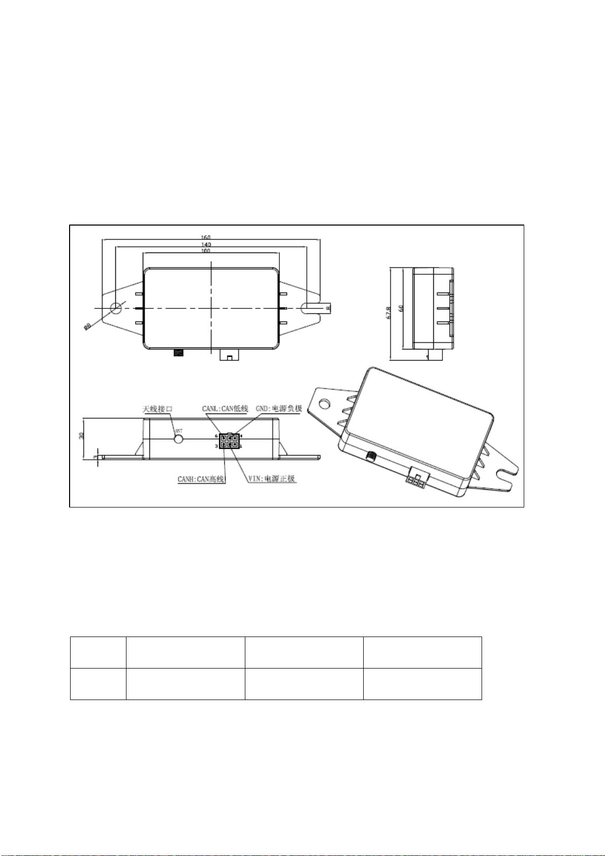
1.3.1. MODULE INTERFACE CIRCUIT AND INSTALLATION DIMENSION
Note: ANT is antenna interface. Wire is extended to vehicle chassis. Le ngth of wire is defined by vehicle
manufacturer according to different vehicle models.
1.3.2. DEFINITION OF PORT
z CAN BUS port:
Socket type: MOLEX 39-01-2060 or 5569-06AIS(corresponding plug model as 39-01-2060 or
5557-06R) 6pin
Definition of pin:
5 pin 2 pin 3 pin 6pin
GND
(black)
z RF port:
REVERSE SMA port (90° angle)
2
VIN(DC24/12V
compatible, red)
CANH(yellow)
CANL(green)

CAN module
1.3.3. FUNCTIONS
1.3.3.1.
When tire pressure is≥10.8Bar(8.3*1.3), high pressure warning level two, potential risky status, driver
shall stop the vehicle and adjust tire pressure immediately.
When tire pressure is≥9.5Bar(8.3*1.15), high pressure warning level one, it calls driver’s attention to
tire pressure and adjust tire pressure accordingly.
HIGH PRESSURE WARNING
1.3.3.2. LOW PRESSURE WARNING
When tire pressure is < 7.4Bar(8.3*0.9), low pressure warning level one, it calls driver’s attention to
tire pressure and adjust tire pressure accordingly.
When tire pressure is< 6.6Bar(8.3*0.8), low pressure warning level two, potential risky status, driver
shall stop the vehicle and adjust tire pressure immediately.
1.3.3.3. HIGH TEMPERATURE WARNING:
When tire pressure is≥80℃, it gives out high temperature warni ng, driver shall stop the vehicle and
lower the temperatu re of the tire.
1.3.3.4. FAST LEAKAGE WARNING:
When the tire pressure loss is ≥0.33Bar within 16s, it gives out fast leakage warning, driver shall stop the
vehicle and make appropriate treatment.
1.3.3.5. NON-RECEIVING DATA WARNING:
When the system does not receive tire pressure information for more than 20 minutes, it gives out nonreceiving data warning.
1.3.3.6. CAN BUS COMMUNICATIONS
When any of the above 5 kinds of information is received, the system will send data to ICM through CAN
BUS for processing.
1.3.3.7. DATA STORAGE
The system can store 4300 of tire information. Under norm al conditions, data shall be stored every 30
minutes; under abnormal condition, data shall be stored every 10s. When abnormality occurs in any tire,
the stored information shall be reviewed. The function is similar to Black Box.
1.3.3.8. ID LEARNING
The module communicates with TPMS Smart Tool and realizes ID LEARNING;
To make integration of TPMS to vehicles simple, save installation time, our proposed installation process is
as follows:
3

CAN module
g
T
T
g
st
ar
t
Sensors
preparati
on
Use tool, read
tire ID,
establish oneto-one
relationship
between tire
ID and tire
location
Sensor
installed
onto
wheels
ires
installati
on
write tire ID and
location into
receivin
by TPMS smart
tool
module
Receivin
g
module
installati
on
wirin
Test
ires
installation
line
Chassis
installatio
n line
End
Body
instal
lation
line
1.3.3.9. CAN BUS COMMUNICATIONS PROTOCOL
• CAN BUS communications protocol is based on J1939
• Transmission rate: 250Kbits/S
• CAN2.0B, Extended Super Frame
• Recommend circuit:
Note:The load resistor (marked R223)whether to need depends on the CAN bus design.
• Communications time sequence:
1)Under normal conditions: All tire data are transmitted every 10S after the first data is received; the
time interval between every two tires is 100ms.
4

CAN module
2)Under abnormal conditions: When an abnormal data is received, it will be transferred through CAN
BUS immediately.
3)Under abnormal conditions: All abnormal tire data are transmitted every 10S, the time interval
between every two tires is 100ms.
5

CAN module
r
a
l
g
i
o
n
e
m
N
warning
hi
h
warning
Explanation
The low order 4 bits represent a
position number, counting left to
right when facing in the
direction of normal vehicle
travel (forward).
The high order 4 bits represent a
position number, counting front
to back on the vehicle.
Examples: 0x23 would be right
outside rear rear on a 3-axle
tractor with dual axle per
side(3rd axle,4th tire)
Pressure at which air is
contained in cavity formed by
tire and rim, 5.5kpa/bit
Example:0x79(Hex)means the
pressure:
121(Dec)
*5.5=665Kpa=6.65Bar=6.6Bar
Temperature at the surface of the
tire sidewall, 0.03125℃/bit
Example:Byte3:0x8D(HEX);
Byte4:0x24(HEX)
0x248D(HEX),Dec value:9357;
absolute temperature:
9357*0.03125=292.4
Celsius degree:292.4-273=19.4℃
00=Normal, 01=Not receive the
tire signal in the past 20
minutes, Others=Rev.
00=Normal
01=Leakage
Others=Rev.
00=Normal
01=high temperature warning
Others=Rev.
The pressure loss rate of a tire.
Example:Byte6:0x8D;Byte7:0x24
0x248D(HEX),dec value 9357;
Leakage rate:
9357*0.1=935.7Pa/s=9.35Kpa/s=0.09
Bar/s Pressure warning range
000=Over high pressure, P≥
10.8Bar;
001=High pressure,9.5Bar≤P<
10.8Bar;
010= Normal:7.4Bar≤P<9.5Bar
011= Low pressure:6.6Bar≤P<
7.4Bar;
Unavail
Data
Data
Physical
Physica
Er
Def
able
maximum
minimum
maximum
minimum
value
or
ult
value
value
value
value
255
Offset
Ratio
factor
Unit
th
Len
n
t
locati
StartB
8
1.1
250
0
1000
0
0
5.5
kPa
8
2.1
64255
0
1735
-273
-273
0.03125
degC
16
3.1
2
5.5
2
5.3
2
5.1
64255
0
6425.5
0
0
0.1
Pa/s
16
6.1
100=Over low pressure:P<6.6Bar
3
8.6
Sig
Truans
Signal
Parameter
Period
BCM_Gat
CAN ID
PGN
name
0x18FEF433
65268
Tire
Condition
0x18FEF433
65268
Tire
Condition
0x18FEF433
65268
Tire
Condition
0x18FEF433
0x18FEF433
0x18FEF433
65268
65268
65268
Tire
Tire
Condition
Tire
Condition
Condition
0x18FEF433
65268
Tire
Condition
0x18FEF433
65268
Tire
Condition
(ms)
al
typ
SPN
eway
Node
itting
on
descripti
Signal name
Tire
10000
929
ICM
TPMS
position
Tire Location
Tire
10000
241
ICM
TPMS
pressure
Tire Pressure
10000
242
ICM
TPMS
re
Tire
temperatu
Tire
Temperature
10000
10000
10000
1697
1698
1699
ICM
ICM
ICM
TPMS
TPMS
TPMS
g
on-
data
Leakage
receiving
Fault
Electrical
CTI Wheel End
CTI Tire Status
re
warning
temperatu
CTI Wheel
Sensor Status
10000
2586
ICM
TPMS
rate
leakage
Pressure
Tire Air
Leakage Rate
10000
2587
ICM
TPMS
level
warning
Pressure
Threshold
Detection
Tire Pressure
6

CAN module
1.4. TECHNICAL PARAMETERS
1.4.1. OPERATING CONDITIONS
Normal operating conditions
• Operating Temperature: -40℃—+85℃;
• Relative humidity: 45%—75%;
• Pressure: 86Kpa—106Kpa(absolute pressure value)
• Storage temperature range: -40℃—+85℃.
1.4.2. PROPERTIES PARAMETER
• Voltage supply: 12V or 24V
• Receiving sensitivity: -95dbm~-105dbm
1.5. FCC'S AUTHENTICATION ANNOUNCEMENT
This device complies with Part 15 of the FCC Rules. Operation is subject to the following two conditions:
(1) this device ma y not cause harmful inter f erence, and (2) thi s device must a cc ept any interference
received, including interference that may cause un desired operat ion.
This equipment has been tested and found to comply with the limits for a Class B digital devi ce, pursuant
to Part 15 of the FCC Rules. These limits are designed to provide reasonable protection against harmful
interference in a residential installation. This equipment gene rates uses and can radiate radio frequency
energy and, if not installed and used in accordance with the instructions, may cause harmful interference
to radio communications. However, there is no guarantee that interference will not occur in a particular
installation. You can test that if this equipment does cause harmful interference to radio or television
reception by turning the equipment off and on.
Caution content: changes or modifications not expressly approved by the party responsible for compliance
could void the user's author ity to operat e the equipment.
7
 Loading...