

Valor Ultimate Turbochim BR517R, Superflame RF BR517R, ULTIMATE TURBOCHIM 517RF, SUPERFLAME 517RF Installer's Manual
INSTALLER GUIDE
MODEL BR517R
(G.C. 32-032-11)
ULTIMATE TURBOCHIM*
&
SUPERFLAME RF*
Rear Fan Flued
Inset Gas Fires
*Covered b y GB Patent 2.202.622B
Please ke e p in a safe p l ac e for fut ur e r e fe r e n c e
600B 208/02

Please leave this Installer Guide with the user
As supplied, this appliance is for use with natural gas
(G20)
When converted using Valor conversion kit no.591149
this appliance is for use with propane gas (G31)
This appliance is for use in the United Kingdom (GB)
and the Republic of Ireland (IE) only.
CUSTOMER CARE
This Installer Guide gives sufficient details to enable the appliance to be installed
and maintained. If further information is required, our Valor AdviceLine will
be pleased to hel p.
Please telephone 0345 626341 (Local call rates apply)
2

CONTENTS
Page
Appliance data 4
General in s tallation requiremen t s 5
Contents of pack 9
Preparing applian c e f o r installation 10
Wall preparation 11
• General
• Brick et c . building. Appliance in front of wall
• Brick et c . building. Appliance recess e d in wall
• Timber frame buildin g. Applianc e in front o f wall
Electrical in s tallation 16
Installing ap plian c e 17
Electrical tests 18
Terminal guard, front s urroun d & gas s upply
installation
Ceramic coals & walls inst allat ion 21
Full operatin g c h e c ks 22
Final review 24
Servicing & parts replacem ent 25
• Burner plaques replace ment
• Front surround rem o val
• Pilot unit removal
• Burner un it c omplete removal
• Gas tap/F.S.D. & solenoid assembly removal
• Piezo ge n erator rem o val
• Main burner in jector re m oval
• Fan switch re moval
• Electrical control components access
• Distribution block removal
• Air press u re switch rem o val
• Fan removal
Short list of spares 30
11
11
12
14
19
25
26
26
26
27
27
27
27
28
28
28
29
3
PART1: APPLIANCE DATA
This pro duct u ses fu el effect pieces. It makes sen se to ta ke care when ha ndling
these articles to ensure that the release of dust is kept to a minimum
This appliance does not contain any component manufactured from asbestos or
asbestos related prod ucts.
The appliance data label and wiring diagram are on a tie below the burner and
are visible when the bottom front cover is removed.
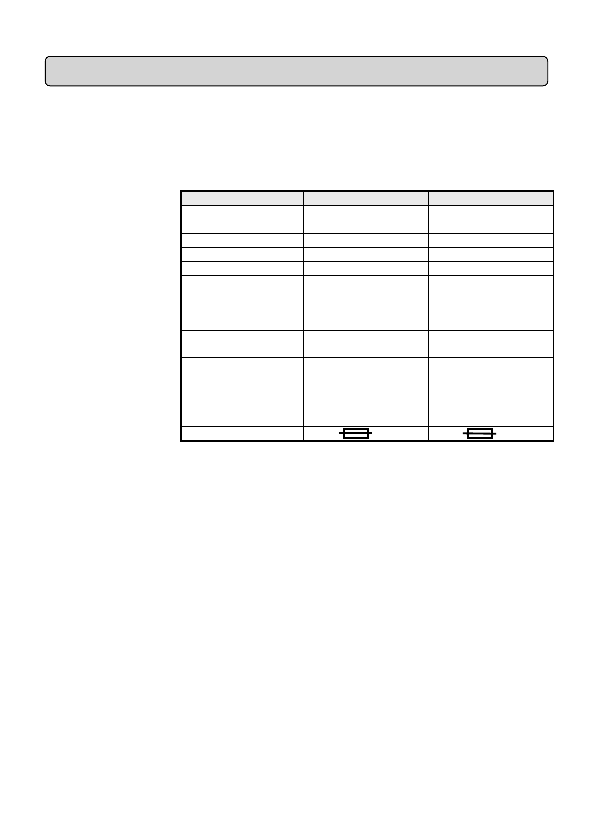
Gas Natural (G20) Propane (G31)*
Inlet P ressure 20mbar 37mbar
Input - Max. (Gr os s ) 6.0kW (20,500B t u/h) 6.1kW (20,800B t u/h)
Input - Min. ( Gro s s) 2.2kW (7,500Btu/h) 3.6kW (12,280B t u/h)
Output - Max. 3.12kW (10,600B t u/h) 3.6kW (12,280B t u/h)
Output - Min 1.1kW (3,750Btu/h) 1.8kW (6,140Btu/h)
Burner Test Pressure
(Cold)
Gas Connection 8mm pipe 8mm pipe
Burner Inje ct or Bray Cat. 18 Size 360 Bray Cat. 18 Size 170
Pilot & Atmosphere
Sensing De vice
Ignition Piezo Electric. Integral
Aeration Non-adjustable Non-adjustable
Electrical supply 230V ~ 50Hz AC 230V ~ 50Hz AC
Fan motor rati ng 55W 55W
Fuse rating 3A 3A
18.2±0.75mbar
(7.3±0.3in w.g.)
SIT Ref. OP9044 SIT Ref. OPLPG9222
with Gas Tap
35.6±0.75mbar
(14.3±0.3in w.g.)
Piezo Electric. Integral
with Gas Tap
.
*When converted using kit 591149
4

PART2:GENERAL INSTALLATION REQUIREMENTS
2.1 The installation must be in accordance with these instructions.
For the user’s protection, in the United Kingdom it is the law that all gas
appliances are installed by competent persons in accordance with the current
edition of the Gas Safety (Installation and Use) Regulations. Failure to install
the appliance correctly could lead to prosecution. The Council for the
Registration of Gas Installers (CORGI) re quires its members to work to
recognised standard s.
In the United Kingdom, all electrical supply installation must be installed in
accordance with t he cur rent edit ion of the IEE Wiring Regulations (BS7671).
In the United Kingdom the installation must also be in accordance with:
a) All the relevant parts of local regulations.
b) The current edition of the Building Regulations issued by the Department
of the Environment and the Welsh Office or the Building Standards
(Scotland) Regulations issued by the Scottish Development Departme nt.
.All relevant codes of practice.
c)
d) The relevant parts of the current editions of the following British
Standards:BS 5440 Part 1
BS 5871 Part 2
BS 6891
In the republic of Ireland the installation must also conform with:
a) The current editions of:-
IS 813
ICP3
IS327
b) All relevant national and local rules in force.
c) The current ETCI National Rules for Electrical Installation.
2.2 Electrical isolation of the unit should be by means of a switched fuse
spur that should be readily accessible to the user, easily identifiable and
preferably sited adjacent to the appliance. It should only connect this appliance.
2.3 This fire is a fan flued appliance for installation on an outward facing wall
of a conventional home which does not have a purpose built flue or chimney.
2.3.1 As supplied, the appliance is suitable for homes constructed of brick,
stone, etc. For homes constructed of brick, stone, etc. the appliance can be
installed into walls up to a maximum thickness as shown below.
If the convecti o n bo x is recessed into the wall: 413mm (16¼ in) max.
If the convection box is i n fr ont of t he finished wall surface: 305mm (12in)
max.
These dimensions are fr om the finished inter na l w all surface (including a n y sur r ound
material) to the external wall surface.
2.3.2 For timber framed build ings, the opti onal clearance bo x p ar t no. 517TFK
must be installed. For timber framed buildings, the appliance is suitable for
walls up to 292mm (11½” ) maximum thickness measured from the external
wall surface to the internal plaste rboard (or similar) wall surface.
Installation to a timber framed building should be in accordance with the
relevant sections of The Institute of Gas Engineers publication IGE/UP/7 “Gas
installations in timber frame buildings”. Please note that advice should be sought
before installing in a timber frame building since the alterations required may
5

nullify any NHBC cover relating to the property. If in doubt, guidance should be
requested from your local authority planning o r building departme nt.
2.4 This appl iance must be mounted wi t h a no n-co m b ust ible hea rt h (n.b
conglomera t e marble hearths are considered as non-combusti b le). The fire box
and fan box m ust b e mounted o n a non-co m b us t ible surface. The he a r t h m ust
project at least 345mm forward of the convection box front and b e at least
620mm wide (See illustrations in “wall preparation” section. The hearth
material must be at least 12mm thick. The periphery of the hearth (or fender)
should be at least 50mm above floor level to discourage the placing of carpets or
rugs over it. For timber framed buildings the hearth must be at least 50mm deep
over all its area so that the clearance box can be satisfactorily installed.
The surface of the hearth must be sufficiently flat to enable the bottom of the
front surround, the burner bracket and the bottom front cover casting to be
aligned horizonta lly. Any excessive unevenness (uneven til es, Cotswol d stone,
etc.) should be rectified.
The appliance must not stand on combustible materials or carpets.
2.5 The appliance must not be fitted directly against a combustible
wall. If the appliance i s to be fitted against a wall with combustible cladd ing or
skirting board, such materials must be removed from the area covered by the
metal outer surround of the appliance. We suggest that the actual surround is
used as a template to mark the area for combustible cl ad d ing removal.
The appli a nce can be fitte d t o a pur po se made propr ietary class “O ” 150° C
surround.
2.6 The opening in the surround or wall recess for the convection box must
be within the limits shown in figure 1(c)
2.7 The minimum allowable distance from the outside edge of the metal
front surround of the appliance to a corner wall having combustible materials is
178mm at either side.
2.8 The front face of the wall should be reasonabl y flat over the area which
will be covered by the convection box top and side flanges to ensure a good
seal.
2.9 The minimum height from the top surface of the hearth to the underside
of any shelf made from wood or other combustible material s is as
follows:-
• For a shelf up to 150mm deep
• Minimum height = 750mm .
• For a shelf deeper than 150mm
• Minimum height = 750m m + 12.5mm for every 25mm d epth over
150mm.
2.10 Note that soft wall coverings (e.g. embossed vinyl, etc.) are easily affected
by heat. They may scorch or become discoloured when close to a heating
appliance. Please bear this in mind when installing.
2.11 The appliance must not be installed in any room which contains a bath or
shower or where steam is regularly present.
6

2.12 An extractor fan may only be used in the same room as this appliance, or
in any area from which ventilation for the appliance is taken, if it does not affect
the safe performance of the appliance. Note the spillage test requirements
detailed further on in this manual. If the fan is likely to affect the appliance, the
appliance must not be installed unles s t he fan is perm a nently dis c onnected.
2.13 A fan-powered flue system t ends to de p ressurise t he room containi ng t he
appliance. Normally no additional ventilation should be required. In
exceptional circumstances, however the spillage check (See further on in this
guide) may indicate a need for further ventilation in order to ensure that there is
adequate air replacement. If necessary seek expert advice.
In the Republic of Ireland (IE), permanent ventilation must comply with the
rules currently in force.
Figure 1
(a) Appliance Dimensions (b) Shelf & Corner Wall Clearances
(c) Opening Requ ir em ents
7
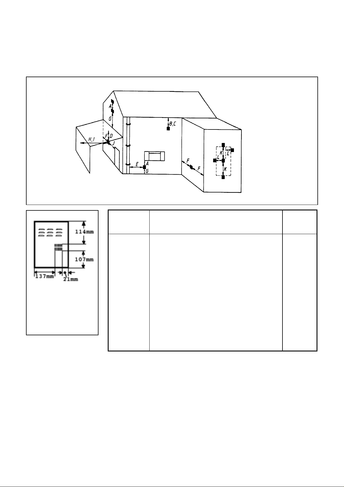
2.14 The flue terminal should be located so that the wind can blow freely
across it at all tim es and where a n y b lo c k a g e du e to lea v es , s n o w , et c . is unlikely.
The minimum allowable distances from the terminal are shown in the
following table and figure 2. Note: The distances are from the edge of the vertical exit
slots in the terminal not from the edges of the rectangular box (See figure 2a).
Figure 2 Terminal positions & minimum distances
Minimum distances for
terminal positions shown
in the table are from slot
openings
Figure 2a
Dimension Terminal Position Minimu
m
Distance
A Directly below an opening, air brick, windows,
300mm
etc.
B Below gutters, soil pipes or drain pipes 75mm
C Bel ow eaves 200mm
D Below balconies or car por t r oo f 200mm
E From a vertical drain pipe or soil pi pe 75mm
F From an internal o r external corne r 200mm
G Above ground, roof or b alcony leve l 300mm
H From a surface facing the t erminal 600mm
I From a terminal facing the terminal 1200mm
J From an opening in a car port (e.g. door,
1200mm
window) into dwelling
K Verticall y from a t erminal on the sa m e wall 1500mm
L Horizontally from a t erminal on the sa m e wall 300mm
M P roje cti on outwards from wall 15mm
2.15 This appliance is suppl ied with a terminal guard . In England and Wales,
the Building Regulations require that the terminal guard is fitted if the flue
terminal can come in contact with people near the buildi ng or be subject to
damage. Even if the regulations do not demand it, we recommend that the
guard is fitted to prevent damage or blockage of the flue system by leaves etc.
2.16 A concealed gas supply conne ct ion can be mad e through the right side
panel or near the right cor ner of the rear p a nel. Visi b le front connect ion can be
from the l eft or right s ide.
2.17 Electrical connection is from the left side.
8
PART3: UNPACKING
The fire front will be one of the following options:
Ultimate black & brass surround
Ultimate all bl ack suerround
Superflame.
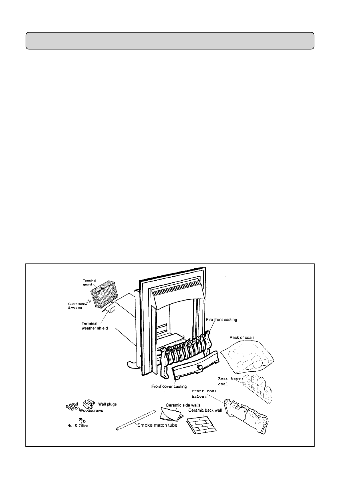
The pack contains:
1 Burner & convection box unit fitted with front surround and fanned flue
unit
1 Nut & olive for 8mm inlet pipe
1 Ceramic back wall
1 Pair of ceramic side walls
1 Front base coal left & right halves
1Rear base coal
1 Pack of 5 loose coals
1Template
1 Smoke match tube
1 Terminal weather shield
1Terminal guard
2 Screws & washers for terminal guard
6 Wall plugs
6 Woodscrews
1 Fire front casting
1 Bottom front cover casting
2 Finials for front cover casting (Superflame only)
1 Literature pack
Carefu lly remove the con tents. Take special c are in ha ndling th e ceramic wa lls
and the coals.
Check that all the listed parts are present and in good condition.
Figure 3 Pack contents
9
PART4:PREPARING APPLIANCE FOR INSTALLATION
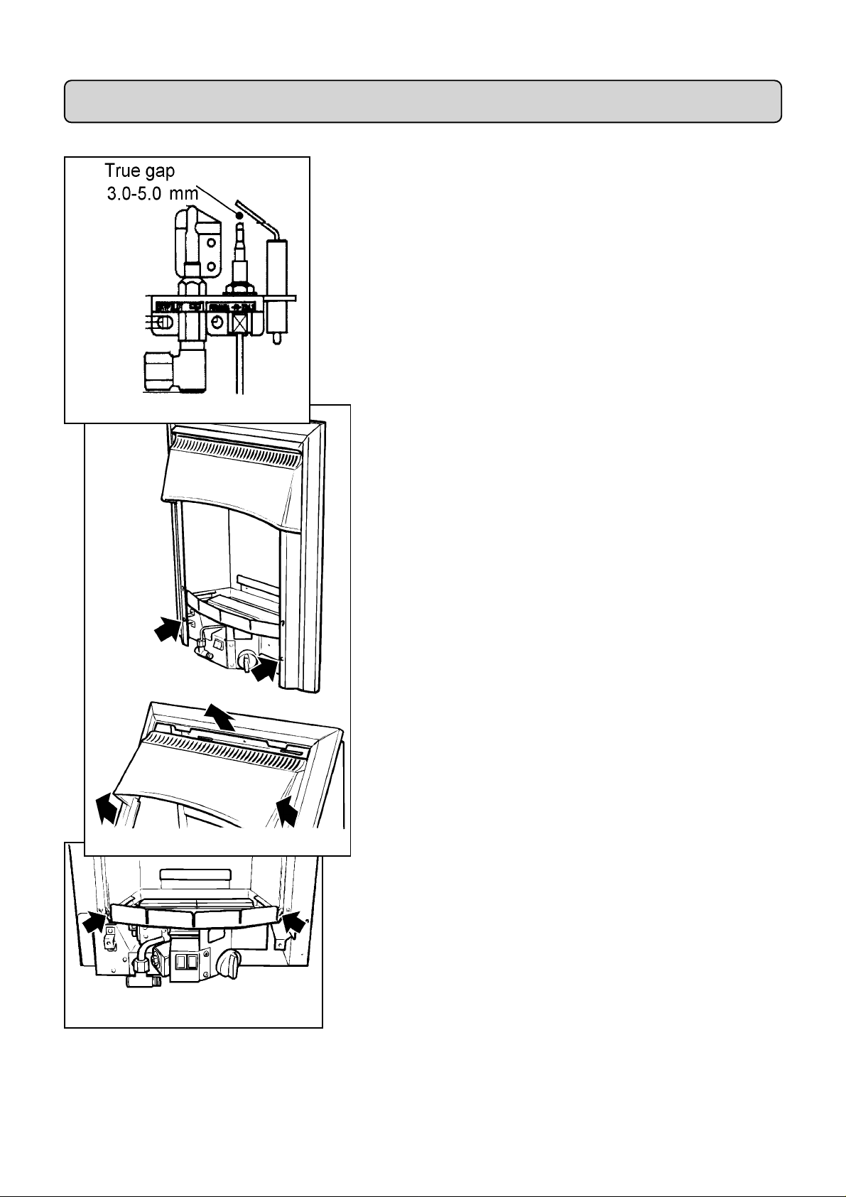
4.1 Check ignition spark
Before attempting to install, it is worth checking that the piezo electric
spark ignition system operates satisfactoril y.
To initiate the spark, depress the control knob and while keeping it
depressed, turn anticlockwise through approximately 60° to the
“PILOT/IGN” position. A spark should track from the electrode pin to
the thermocouple tip. If there is no spark or incorrect tracking, check
the spark gap between the electrode wire and thermocouple tip (see
figure 4). If the spark gap is correct, check the ignition wiring.
Figure 4 Pilot Ignition System
4.2 Remove the two screws securing the bottom of the front
surround to the sides of the convection box. Raise the front
surround to allow the retaining lugs at the top to clear the slots in
the convection box hood and then lift clear (see figure 5).
Figure 5 Front Surround Removal
Figure 6 Burner Removal P oints
4.3 In the majority of cases (Fixing the appliance to th e floor,
removal of mains cable for ease of connection to isolating
switch ), the b urn er u nit w ill need t o b e det ach ed. D etac h the bu rn er
unit from the convection box by removing two screws (see figure 6).
10
 Loading...